Embed Size (px)
Citation preview

OM0247 Page 1 of 52
Pharmagard™ Negative Pressure Recirculating Sterile Isolator
Models NU-NR800-400/600
Bench/Console
Operation & Maintenance Manual
December, 2017 Revision 4
Series 30 and Higher
Manufactured by: NuAire, Inc.
2100 Fernbrook Lane Plymouth, Minnesota USA 55447
Toll Free: 1-800-328-3352 In MN: 763-553-1270
Fax: 763-553-0459 www.nuaire.com

OM0247 Page 2 of 52 Rev 4 December/2017
Congratulations!
You have just purchased one of the finest negative pressure recirculating sterile Isolators available. With proper care, maintenance (certification), and pharmacy procedure, this Isolator will give you years of product protection from particulate contaminants as prescribed in the USP 800 and personnel protection as recommended by OSHA and NIOSH. Please read this manual carefully to familiarize yourself with proper installation, maintenance, and operation of the Isolator. Other reference and guideline materials are available through the following web sites.
www.usp.org www.ashp.org
www.cdc.gov/niosh/docs/2004-165 www.cetainternational.org
www.osha.gov/dts/osta/otm/otm_toc.html (Section 6)

OM0247 Page 3 of 52 Rev 4 December/2017
ABOUT THIS OPERATION & MAINTENANCE MANUAL
The information contained in this manual is intended to reflect our current production standard configuration model along with the more frequently purchased options. Any unique additions /modifications /shop drawings are appended in the back flap of this manual, along with any modifications and/or additions to procedures as outlined in this manual. A copy of the original factory test report is also appended to this manual. In case this manual and/or test report is lost or misplaced, NuAire retains a copy in our files. A replacement copy can be obtained by calling or writing NuAire, Inc. stating the model number and serial number and a brief description of the information desired.

OM0247 Page 4 of 52 Rev 4 December/2017
Pharmagard™ Negative Pressure Recirculating Sterile Isolator Models NU-NR800-400/600
Operation & Maintenance Manual
TABLE OF CONTENTS
Section No. 1 ........................................................................ General Description Section No. 2 ........................................................................ Models & Features Section No. 3 ........................................................................ Warranty Section No. 4 ........................................................................ Shipments Section No. 5 ........................................................................ Installation Instructions
5.1 ................................................................................... Location 5.2 ................................................................................... Set-up Instructions 5.3 ................................................................................... Certification Testing Methods and Equipment
Section No. 6 ........................................................................ Operating the NU-NR800 6.1 ................................................................................... Operator Controls & Indicators 6.2 ................................................................................... Operating Guidelines 6.3 ................................................................................... Operating Sequence 6.4 ................................................................................... Ergonomics
6.5 ................................................................................... Cleaning Procedure 6.6 ................................................................................... Sleeve/Glove Usage
Section No. 7 ........................................................................ General Maintenance 7.1 ................................................................................... Decontamination 7.2 ................................................................................... Fluorescent Lamp Bulb Replacement 7.3 ................................................................................... HEPA Filter Replacement 7.4 ................................................................................... Motor/Blower Replacement 7.5 ................................................................................... Airflow Calibration 7.6 ................................................................................... Filter Integrity Check 7.7 ................................................................................... Cleanliness Classification Test 7.8 ................................................................................... Enclosure Integrity Test 7.9 ................................................................................... Main Control Board Description & Replacement
Section No. 8 ........................................................................ Error Indicators & Troubleshooting Section No. 9 ........................................................................ Remote Contacts Section No. 10 ...................................................................... Optional Equipment
10.1 ................................................................... Sharps/Garbage Disposal System for Hazardous Drugs Section No. 11 ...................................................................... Electrical/Environmental Requirements Section No. 12 ...................................................................... Polycarbonate Material Compatibility Section No. 13 ...................................................................... Disposal and Recycle
Insert ...................................................................... Replacement Parts
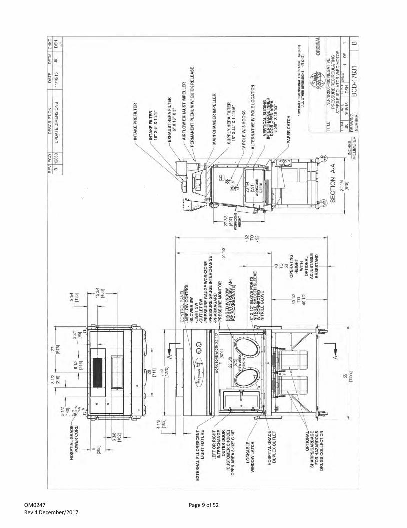
MANUAL DRAWINGS ACD-18093............................................ NU-NR800 Airflow Schematic BCD-17831 ............................................ NU-NR800-400 Specification Drawing BCD-17832 ............................................ NU-NR800-600 Specification Drawing BCD-17843 ............................................ NU-800 Front Panel (Label)
ASSEMBLY DRAWINGS
BCD-10483 ............................................ Negative Isolator Sleeve/Glove Replacement Procedure BCD-17841 ............................................ NU-NR800 Base Assembly BCD-17839 ............................................ NU-NR800 Control Center BCD-10400 ............................................ NU-800 Bench Mount Installation BCD-10476 ............................................ NU-800 Telescoping Base Support BCD-10480 ............................................ NU-800 Adjustable Base Support BCD-13593 ............................................ Assy. Waste/Sharps Disposal for Hazardous Drugs
ELECTRICAL SCHEMATICS
BCD-18420 ............................................... NU-NR800-400/600 Electrical Schematic

OM0247 Page 5 of 52 Rev 4 December/2017
Pharmagard™ Negative Pressure Recirculating Sterile Isolator Models NU-NR800-400/600
MANUFACTURED BY: NuAire, Inc. - Plymouth, Minnesota, U.S.A.
1.0 General Description
The Pharmagard model NU-NR800 negative pressure recirculating sterile Isolator is a bench/table top model, optionally available with several base stand configurations for operation as a console model. The NU-NR800 Isolator is designed to provide a sterile negative pressure work environment for the compounding of hazardous drugs. The NU-NR800 Isolator creates HEPA filtered unidirectional flow supply at 20 air changes per minute within both the work zone and interchange areas to assure ISO Class 5 (formerly, Federal Standard 209E, Class 100) conditions. Utilizing unidirectional flow assures a continuous stream of HEPA filtered air across the work zone and interchange areas assuring sterility and minimizing cross contamination. Once the air is through the work area, the airflow is split to front to rear. Then proceeds under the work tray, up the rear divider panel and is partially re-circulated again through the supply HEPA or exhausted through the exhaust blower/HEPA filter assembly. The exhaust blower/HEPA filter assembly provides the negative pressure for Isolator containment. The exhaust air is drawn from the re-circulating Isolator airflow as described above. In addition, an intake HEPA filter is located just in front of the exhaust filter-providing make up air for the Isolator. It is strongly recommended that the exhaust air volume be ducted to the outside per NIOSH guidelines. NuAire offers a canopy exhaust transition as an accessory to connect to the facility exhaust system.

OM0247 Page 6 of 52 Rev 4 December/2017
1.2 Safety Instructions These safety instructions describe the safety features of the PHARMAGARD Model NU-NR800 Isolator.
The Isolator has been manufactured using the latest technological developments and has been thoroughly tested before delivery. It may, however, present potential hazards if it is not used according to the intended purpose or outside of operating parameters. Therefore, the following procedures must always be observed:
The Isolator must be operated only by trained and authorized personnel.
For any operation of this unit, the operator must prepare clear and concise written instructions for operating and cleaning, utilizing applicable safety data sheets, plant hygiene guidelines, and technical regulations, in particular.
o which decontamination measures are to be applied for the cabinet and accessories o which measures are to be taken in the case of an accident
Repairs to the device must be carried out only by trained and authorized expert personnel.
Keep these operating instructions close to the unit so that safety instructions and important information are always accessible.
Should you encounter problems that are not detailed adequately in the operating instructions, please contact your NuAire Representative of NuAire technical Services.
1.3 Explanation of Symbols
CAUTION used without the safety alert symbol indicates a potentially hazardous situation which, if not avoided, may result in property damage.
Potential electrical hazard, only qualified person to access.
Note: Used for important information.
Ground, Earth
CAUTION
Lead Free
Chemical Hazard
Flammable Hazard
Hazardous Gases! Personal Protection Equipment Required.
Safety alert symbol indicates a potentially hazardous situation which, if not avoided, could result in death of serious injury.
Safety alert symbol indicates a potentially hazardous situation which, if not avoided, may result in minor or moderate injury.
WARNING !
CAUTION !

OM0247 Page 7 of 52 Rev 4 December/2017

OM0247 Page 8 of 52 Rev 4 December/2017
2.0 Models & Features The model NU-NR800, Negative Pressure Recirculating Sterile Isolator is manufactured in two sizes: 4 ft. and 6 ft.
OM0247 Page 9 of 52 Rev 4 December/2017

OM0247 Page 10 of 52 Rev 4 December/2017

OM0247 Page 11 of 52 Rev 4 December/2017
3.0 Warranty
NuAire, Inc. warrants that it will repair F.O.B. its factory or furnish without charge F.O.B. its factory a similar part to replace any material in its equipment within 36 months after the date of sale if proved to the satisfaction of the company to have been defective at the time it was sold provided that all parts claimed defective shall be returned, properly identified to the company at its factory, charges prepaid. Factory installed equipment or accessories are warranted only to the extent guaranteed by the original manufacturer, and this warranty shall not apply to any portion of the equipment modified by the user. Claims under this warranty should be directed to NuAire, Inc. setting forth in detail the nature of the defect, the date of the initial installation and the serial and model number of the equipment. This warranty shall not apply to any NuAire product or part thereof which has been subject to misuse, abuse, accident, shipping damage, improper installation or service, or damage by fire, flood or acts of God. If the serial number of this product is altered, removed or defaced as to be illegible, the Warranty shall be null and void in its entirety. The warranty is for the sole benefit of the original purchaser and is not assignable or transferable. Before returning any item, for any reason, contact NuAire for a Return Authorization Number. This number must accompany all returns. Any product shipped to NuAire without this number will be returned refused shipment or collect freight.
4.0 Shipments
NuAire takes every reasonable precaution to assure that your PHARMAGARD Isolator arrives without damage. Motor carriers are carefully selected and shipping cartons have been specially designed to insure your purchase. However, damage can occur in any shipment and the following outlines the steps you should take on receipt of a NuAire PHARMAGARD Isolator to be sure that if damage has occurred, the proper claims and actions are taken immediately.
4.1 Damaged Shipments
4.1.1 Terms are factory, unless stated otherwise. Therefore, it is important to check each shipment before acceptance.
4.1.2 If there is visible damage, the material can be accepted after the driver makes a notation on the consignee's copy
of the freight bill. Then an inspection must be made to verify the claim against the carrier. This inspection is the basis of your filing the claim against the carrier.
4.1.3 If concealed damage is found, it is absolutely necessary to NOTIFY THE FREIGHT AGENT AT ONCE, and request an
inspection. Without this inspection, the transportation company may not accept a claim for loss or damage. If the carrier will not perform the inspection, an affidavit must be prepared stating that he was contacted on a certain date and that he failed to comply with the request. This along with other papers in the customer's possession will support the claim.

OM0247 Page 12 of 52 Rev 4 December/2017
5.0 Installation Instructions
5.1 Location The location or placement of the Isolator within the pharmacy or nursing station should consider contamination risks, processes and procedures requirements for each Isolator. It is preferred, but not necessary to locate the Isolator within an ISO Class 7 buffer air quality area. When the isolator is used for the preparation of sterile hazardous drug compounding, per USP chapter (800), it must be located in an ISO Class 7 buffer room, or in an unclassified containment segregated compounding area (if the beyond-use-date criteria is followed) from USP800). The Isolator should be located away from personnel traffic lanes, air vents, doors, or any other source of disruptive air currents. Being an Isolator, disruptive air currents will not affect performance. However, it may affect the process of work product movement in and out of the Isolator. In addition, it may affect ergonomic user comfort. Placing the Isolator away from disruptive air currents will assure maximum CSP sterility and user comfort. Where space permits, a clear 4" (102mm) area should be permitted on all sides of the Isolator. The electrical outlet into which the Isolator is connected should be readily accessible for maintenance purposes. Do not position the cabinet to prevent access to the power cord. The power cord plug serves as the disconnect and should remain readily accessible. If the outlet is inaccessible, such as a conduit (hardwired) connection, then an appropriate warning label should be applied near the cabinets on/off switch to indicate the circuit breaker on the power distribution panel to be used. Per OSHA, NIOSH and ASHP, it is strongly recommended that the Isolator be exhausted to the outside. Per USP chapter (800), all Compounding Primary Engineering Controls used in the preparation of sterile hazardous drugs must be externally vented. The exhaust system should be dedicated and treated as containing hazards and identified as such. Use applicable federal, state and local codes as well as, NFPA and ANSI/AIHI Z 9.5 for exhausting references. When exhausting the NU-NR800, NuAire recommends the use of a canopy transition. See separate sheet for discussion of exhaust transition.
5.2 Set-up Instructions Remove outer shipping protection (carton or crating). The Isolator is fastened to the base skid and it is usually the best procedure to leave the skid in place until the Isolator is located in its approximate location to facilitate ease in handling. It can then be removed form the skid by removing the banding, bolts, and screws holding the Isolator to the skid.
NOTE: There is a base filler panel on the Isolator bottom. If using forklift, the forks should avoid the filler panel area.
The Isolator is attached to the skid in two methods depending upon the type of bench mount or base stand purchased. If the Isolator is directly attached to the skid, remove and place on bench mount. If the Isolator is shipped with the base stand attached, follow the instructions below for Isolator removal from the skid. CAUTION, IT IS RECOMMENDED THAT NO LESS THAN TWO PEOPLE PERFORM THE SKID REMOVAL AND CASTOR/LEG LEVELER ATTACHMENT PROCESS. 5.2.1 Telescoping Base Support (BCD-10476)
The telescoping base stand is shipped installed and attached to the Isolator at its lowest height. Remove the brackets and banding holding the Isolator to the base skid. Remove the Isolator from the skid. PLEASE NOTE THE BASE FILLER PANEL IF USING A FORKLIFT. To position higher, remove 3/8” bolts (2) on each leg and raise to desired height. Re-install 3/8” bolts (2) on each leg to lock in desired height.
5.2.2 Adjustable Base Support (BCD-10480) The adjustable base support is shipped installed, attached to the Isolator at its lowest height. Remove the skid brackets and banding holding Isolator to the base skid. Remove Isolator from skid by pushing Isolator off skid one corner at a time attaching either castors or leg levelers on each corner as the base plates overhang the skid. PLEASE NOTE THE BASE FILLER PANEL IF USING FORKLIFT. ALSO, IF FORKLIFT IS USED, LEAVE BASE PLATE SHIPPING BRACKET IN PLACE UNTIL ISOLATOR IS PLACED ON THE FLOOR. Once Isolator is placed on floor with either castors or leg levels, remove base plate holding bracket. Adjustable base support can now be plugged in and height adjusted with up/down switch.

OM0247 Page 13 of 52 Rev 4 December/2017
5.2.3 Leveling w/Leg Levelers Using a level placed on the work tray, adjust the leg levelers first end-to-end, then, front to back. The NSF
approved leg levelers provide a 3/4" (20mm) adjustment. 5.2.4 Bench Mount Installation
Place 2 X 2 bench mount bars on bench from front to rear the same width as the Isolator. Attach the 2 X 2 bars to the bench with the brackets provided.
Note: No more than a 4-1/2 inch (144mm) 2 x 2 bar overhang is permitted for bench top installation.
Place the Isolator on the 2 X 2 bench mount bars. Attach Isolator to the bars with plate mounts. Lastly, attach plate mount covers. If desired, the joint between the bench and Isolator mounts may be sealed with silicon RTV to prevent spills from migrating under the bench mount system.
5.2.5 Gas Service
NuAire doesn't recommend the use of natural gas within the Isolator. All NuAire Isolator’s have precautionary warning labels that say the following:
Use of explosive or flammable substances in this Isolator should be evaluated by your appropriate safety personnel.
5.2.6 Plumbing Services
Ground key cocks with the type of service specified by the removable button on the handle, are located in the work zone. The Ground Key cocks are not recommended for pressure over 30 p.s.i. (2.0 BAR). Reducing valves should be installed external to the Isolator if necessary. Ground key cocks should never be used for flammable gasses or oxygen service. A special needle valve for oxygen service or certified valve is required and available upon request.
External connection is to 3/8 inch NPT coupling in the inner sidewalls. Connection to plant utilities should be made with proper materials for the individual service and according to national and/or local codes. Observe all labels pertaining to the type of service and operating pressure.
5.2.7 Drain Valve The Isolator may or may not come with the drain valve installed depending upon the basestand type purchased. If the drain valve requires installation, remove from packaging. Apply thread lock liquid provided in package and attach to threaded drain stub located on the bottom right side of the Isolator. Tighten so handle is located on the left side of valve, so the handle will be pulled forward to close the drain.
5.2.8 Electrical Services
The NU-NR800 series Isolator is connected via an electrical power cord with hospital grade plug or optionally, “hardwired”. The unit requires 115 VAC, 60 Hz, single phase (current rating varies per Isolator size, reference Electrical/Environmental Requirements). It is recommended that power to the unit be on its own branch circuit, protected with a circuit breaker or fuse at the distribution panel. CAUTION: THIS UNIT CONTAINS ELECTRONIC BALLASTS FOR THE FLUORESCENT LIGHTING. ELECTRONIC BALLASTS OPERATE WITH HIGH INRUSH CURRENT. IT IS NOT RECOMMENDED TO USE THIS PRODUCT WITH GROUND FAULT CIRCUIT INTERRUPTERS (GFCI'S) BECAUSE THE BALLASTS MAY CAUSE THE GFCI TO TRIP.
CAUTION !

OM0247 Page 14 of 52 Rev 4 December/2017
5.2.9 Final Assembly REMOVE THE PROTECTIVE CARDBOARD COVER OVER THE INLET AND EXHAUST FILTER, located on top of the Isolator. The powder coat urethane and polycarbonate glove port panel is easily cleaned with any mild household detergent. Use a soft cloth on the panels. Recommended cleaners for Polycarbonate are:
Formula 409 (for external surfaces only)
Windex D w/Ammonia D (for external surfaces only)
70% Isopropyl Alcohol The use of polycarbonates has some important don'ts:
Do Not use abrasive or high alkaline cleaners.
Do Not scrape with squeegees, razor blades, or other sharp instruments. Please refer to section 12.0 for Polycarbonate Material Compatibility. Do not attempt to clean the HEPA filter media. Isolator interior walls or work surface are easily cleaned with any mild household detergent cleaner using a soft cloth.
5.3 Certification Testing Methods and Equipment After installation and before use, NuAire recommends that the Isolator be certified or commissioned to factory standards. At a minimum, the following tests should be performed.
1. HEPA Filter Leak test 2. Downflow Velocity test 3. Isolator Pressure (calibration) test 4. Cleanliness Classification test 5. Enclosure Integrity test
The testing methods and equipment required are specified on the factory inspection report included with this manual (see insert in back cover). Once complete, verify user menu language desired.
IT IS RECOMMENDED THAT THESE TESTS BE PERFORMED BY A QUALIFIED TECHNICIAN WHO IS FAMILIAR WITH THE METHODS AND PROCEDURES FOR CERTIFYING ISOLATORS. PLEASE VISIT THE NUAIRE WEBSITE, WWW.NUAIRE.COM UNDER TECH-SERVICE SUPPORT AND REVIEW INDEPENDENT SERVICES TECHS FOR YOUR AREA. AFTER THE INITIAL CERTIFICATION, NUAIRE RECOMMENDS THAT THE ISOLATOR BE RECERTIFIED AT A MINIMUM ON AN ANNUAL BASIS OR MORE OFTEN IF REQUIRED BY REGULATORY REQUIREMENTS AND AFTER EVERY FILTER CHANGE OR MAINTENANCE ACTION OR ANY TIME THE OPERATOR FEELS IT IS NECESSARY. Note that the Pharmagard Isolators, filters, and seals provide premium performance. Quality Control in both design and manufacturing assure superior reliability. However, protection to product and is so vital that certification to the performance requirements should be accomplished as stated by the factory standards.

OM0247 Page 15 of 52 Rev 4 December/2017
Pharmagard™ Negative Pressure Recirculating Sterile Isolator Models NU-NR800-400/600
* For total weight, must select and add (1) of (3) base options.
Catalog Number
Catalog Number NU-NR800-400 Nominal 4 foot (1.2m)
NU-NR800-600 Nominal 6 foot (1.8m)
Performance Specifications 1. Product Protection
CETA CAG-002-2006 ISO Class 5 (Unidirectional Flow)
CETA CAG-002-2006 ISO Class 5 (Unidirectional Flow)
Style of Isolator Bench top/console Isolator Bench top/console Isolator
Isolator Construction Welded stainless steel 16GA, Type 304 pressure tight design
Welded stainless steel 16GA, Type 304 pressure tight design
Interchange Chamber ISO Class 5 With Internal/External Sealed Doors
ISO Class 5 With Internal/External Sealed Doors
Diffuser for Air Supply (Metal) Non-flammable Non-flammable
HEPA Filter Seal Type: Supply Filter-99.99% Eff. on 0.3 microns Exhaust Filter-99.99% Eff. on 0.3 microns
Neoprene, Spring-loaded Under Negative Pressure
Neoprene, Spring-loaded Under Negative Pressure
Standard Services: Hospital Grade Duplex Outlet
One, Backwall
One, Backwall
Optional Services: Service Valves 3/8" NPT
Up to 3
Up to 3
Isolator Size Inches (mm): Height Height (Minimum w/opt. Adjustable Base Stand) Width Depth (with Control Center)
51 3/4 (1314) 81 3/4 (2076) 50 (1270) 32 1/2 (826)
51 3/4 (1314) 81 3/4 (2076) 74 (1880) 32 1/2 (826)
Work Zone Inches (mm): Width Height Depth (Center of Glove Port)
35 1/4 (870) 27 3/8 (695) 23 1/4 (591)
59 1/4 (1505) 27 3/8 (695) 23 1/4 (591)
Interchange Inches (mm) Width Depth (at Work Surface) Height
14 1/8 (359) 24 (610) 27 3/8 (695)
14 1/8 (359) 24 (610) 27 3/8 (695)
Hinged Viewing Window (Polycarbonate) Fully closed to fully open Fully closed to fully open
Exhaust CFM/CMH Standard/Optional: Canopy NU-916-797 Plan Duct Static Pressure Eng/Metric: (water gauge)
200/340 0.05-0.1”/1.24-2.54 mm
225/382 0.05-0.1”/1.27-2.54 mm
Heat Rejected, BTU, Per Hour 795 1136
Electrical: Volts, AC 60 Hz Amps: Blower/Lights Amps: Hospital Grade Duplex Amps: Total 12 ft. Hospital Grade Power Cord (one)
UL/UL-C Listed 115 3 3 6 14 GA - 3 Wire, 15A
UL/UL-C Listed 115 5 3 8 14 GA - 3 Wire, 15A
*Crated Shipping Weight: *Net Weight: Net Optional Adjustable Automatic Base Stand Wt: Net Optional Telescoping Base Stand Wt: Net Optional Bench Mount Wt:
490-lbs. /222 kg. 440-lbs. /200 kg. 150-lbs. /68 kg. 60-lbs. /27 kg. 20-lbs. /19 kg.
640-lbs. /290 kg. 590-lbs. /268 kg. 160-lbs. /73 kg. 70-lbs. /32 kg. 20-lbs. /19 kg.

OM0247 Page 16 of 52 Rev 4 December/2017
6.0 Operating the NU-NR800
6.1 Operator Controls & Indicators
6.1.1 Overview The FlowGard™ electronic control system is designed to service the control requirements of the NU-NR800. The control system consists of an electronic module that will perform the following functions:
Easy user interface via OLED (Organic Light Emitting Diode) display/function keys
Language selectable user interface menus (English, Spanish, German, French, Chinese and Japanese)
Control blower via solid state switch.
Control lights via solid state switch.
Control outlets via solid state switch.
Control supply blower DC ECM motor with solid-state DC Motor Controller.
Display time of day.
Independent of the control system is a potentiometer to regulate the control of the exhaust blower.
The NU-NR800 offers the latest digital microprocessor design technology for improved cabinet performance and safety. The main control module, through the use of the front panel, controls the on/off functions of the blowers, fluorescent lights and outlets. All the above functions are shown in a system block diagram (see figure 1).
Figure 1

OM0247 Page 17 of 52 Rev 4 December/2017
6.1.2 Front Panel The control system front panel contains the following functions described in detail (see Drawing BCD-17843).
6.1.2.1 Blower Key The blower key controls the ON/OFF power to the blower. LED above key indicates: Full green for blower on Blinking green for blower pending Blinking full red for blower alarm 6.1.2.2 Hidden Key The hidden key is located just above the blower LED indicator centered in the airflow symbol. The hidden key
is used for various functions including the blower password 3 key sequence if the option is activated. 6.1.2.3 Fluorescent Light Key The fluorescent light key controls the on/off power to the fluorescent light. LED above the key indicates full blue for fluorescent light on, blinking blue during auto timer duration. 6.1.2.4 Ultraviolet (UV) Light Key (Not Applicable for the NU-800) 6.1.2.5 Outlet Keys The outlet key controls the ON/OFF power to the outlets. LED above indicates full blue for outlets on, blinking blue during auto timer duration. 6.1.2.6 Red Alarm LED The red alarm LED will indicate any alarm condition and remain indicating until the alarm condition is cleared. A blinking red alarm LED indicates a power interruption has occurred. 6.1.2.7 Audible Alarm Silence Key The audible alarm silence key allows user interaction to silence an audible alarm for a period of 15 minutes.
After 15 minutes if the alarm condition still exists, the audible alarm will again sound. The audible alarm silence key also is used to exit all FlowGard™ user interaction menus. 6.1.2.8 Arrow Adjustment Keys The arrow adjustment keys allow user interaction for various functions. 6.1.2.9 ENT Key The ENT key is used to select item on display or accept and enter current item, function or value. 6.1.2.10 Interchange Chamber Minihelic Gauge
The Interchange chamber minihelic gauge displays negative static pressure within the interchange chamber. The gauge is calibrated in “inches of water gauge” pressure. The interchange chamber negative pressure will read less than -0.15” w.g. during normal operation. If the external interchange door is opened, the gauge reading will go to 0.00” w.g. Once the external interchange door is closed, again the reading will decrease back to normal. If the internal interchange door is opened the gauge reading will increase and read the same as the main chamber minihelic gauge.
6.1.2.11 Main Chamber Minihelic Gauge
The main chamber minihelic gauge displays the negative static pressure within the main chamber. The gauge is calibrated in “inches of water gauge” pressure. The main chamber negative pressure will read less than –0.05” w.g. during normal operation. If the external interchange door is opened, an increase will occur. However, if the internal door is opened, the reading will decrease and read the same as the interchange chamber minihelic gauge.

OM0247 Page 18 of 52 Rev 4 December/2017
6.1.2.12 Pharmagard Digital Monitor The Pharmagard Pressure Monitor displays the negative static pressure within the main chamber. The pressure monitor is calibrated in “inches of water gauge” pressure. The pressure monitor will read the same as the main chamber minihelic gauge and in addition, allow a low/high alarm limit point to be set. The default alarm limits is set to -0.03” w.g. high and -1.50” w.g. low.
General The Pharmagard Digital Monitor uses an integrated digital pressure transducer to monitor negative pressure. The monitor indicates through both a segment display and LED’s. The segment display is green and operates to + 0.01” w.g. sensitivity. The LED’s indicate acceptable pressure (green), caution or near alarm points to within 0.005” w.g. (yellow) or alarm condition (red). The monitor starts when the Isolator blower is turned on. Upon start up, all segments displays, and LED’s will light and a short audible alarm will sound to indicate a properly functioning monitor. During the next 4 minutes, the segment display will indicate dashes and green LED will blink during the warm-up period. Once the 4-minute warm-up period is complete, the monitor will measure and display the current main workzone chamber pressure. If the monitor is not functioning properly, the green, yellow and red LED’s will blink to indicate an error. During external door openings, the Isolator pressure will increase and equalize at zero. The monitor will display the high setpoint and indicate a pending alarm. This will initiate a 60 second audible alarm delay for material movement purposes. If the Isolator pressure remains at zero for more than 60 seconds, the audible alarm will sound. The monitor is powered by 15 VDC supplied from the main control board. The monitor also has alarm contacts, COM, NO, NC for external monitoring. All user interaction is accomplished through the arrow and reset keys. It is recommended that the monitor be calibrated during the certification process. NO and COM are used to cut power to the supply blowers when the monitor is in alarm condition.
Nominal Pressure Calibration The Pharmagard Digital Monitor is factory calibrated to match the main workzone chamber minihelic gauge pressure value. This is accomplished through an offset calibration procedure. To accomplish, perform the following once the Isolator has been certified to its proper airflow and the monitor is through the warm-up period.
Press and hold [] and [] arrow key simultaneously for 3 seconds until the red LED blinks and the display alternates “In” and a pressure value.
Use [] and [] arrow keys to adjust the display value to match the main workzone chamber pressure minihelic gauge.
Press *RESET’ key to enter the nominal pressure value (red LED will stop blinking and display will indicated pressure value).
High/Low Alarm Setpoint Calibration The Pharmagard Digital Monitor is factory calibrated to -0.03” w.g. high and -1.50” w.g. low. To verify or to change the alarm setpoints, perform the following procedure.
Press and hold either [] key for high alarm or [] key for low alarm for 3 seconds until the red
LED blinks and the display alternates either “Hi” or “Lo” and a pressure value. Use [] and [] arrow keys to adjust the display value desired.
Press [RESET] key to enter the alarm setpoint value.
Audible alarm The audible alarm should be activated whenever the pressure reaches the high or low alarm setpoint. However, once the alarm pressure is reached, it must stay on the alarm limit foe 5 seconds consistently or it will not recognize it as an alarm. If at any time, the pressure returns to acceptable limits, the alarm would be reset and silenced. Once the 5 second period of constant alarm is present, the audible should sound for 30 seconds, then ring back 1 second every 10 seconds. If the [RESET] key is pressed, the alarm should be silenced for 5 minutes, then continue to ring back for 1 second every 10.

OM0247 Page 19 of 52 Rev 4 December/2017
6.1.3 Control System Power After the NU-NR800 is plugged into the appropriate facility line power the control system will power up and display a power on reset message, the last revision of software (for several seconds) and time. The control panel will also indicate the power up status by blinking the red alarm LED. Pressing any key will acknowledge the power up status and turn off the blinking red alarm LED. If a power interruption occurs, all control system functions, calibrations and parameters will be maintained and continue upon restoration of power. Just as the initial power up, the red alarm LED will blink to indicate power up status along with the display message of power on reset.
6.1.4 Run Mode Operation Operation of the Isolator is initiated by plugging the power cord into the appropriate power connection. In the power off condition (Isolator is unplugged); all calibration and running parameters will be stored in the microprocessor's EEPROM memory. During the power on condition (Isolator is plugged in), the Isolator blowers, lights, and outlets may be turned on. 6.1.4.1 Supply Airflow Control
The supply velocity airflows within the Isolator are controlled by a pulse width modulation (PWM) signal applied to the motor/blowers. The PWM signal is adjustable via the blower calibration section, which varies the PWM signal from 0 to 18 Vdc.
6.1.4.1 Exhaust Airflow Control The negative pressure within the Isolator is controlled by the volume of air exhausted. This can be adjusted by the baffle plates that are located below the intake prefilter on top of the isolator.
Airflow idle XX:XX
NuAire GAF3 Version XX:XX
Power on Reset

OM0247 Page 20 of 52 Rev 4 December/2017

OM0247 Page 21 of 52 Rev 4 December/2017
6.1.5 Standby Mode When the BSC is not in use, the display will indicate the NuAire logo with the current time provided in the upper right corner. Any of the function keys, except the blower that initiates run mode may be turned on and off in standby mode. The cabinet status and main menu may also be accessed for use as needed. FlowGard™ Control System has a screen saver built in for extended OLED life. The screen saver time is 5 minutes. This means after 5 minutes when the blower is not on, the display will go dark. Pressing any key will again illuminate the display.
6.1.6 Run Mode Any time the blower run key is pressed the RUN MODE screen will appear.
The top line will show the items being displayed along with the time of day. The center of the display will show the downflow velocity value that was entered during the last calibration. The bottom of the display or message area will show active alarms and other status information. Status menu auto timers may also be accessed in run mode. Press either ↑ or ↓ keys to move from one menu to the next. Auto timer menu will only indicate active timers as they count down. 6.1.7 Standby/Run Mode Alarms
If present, standby/run mode alarms will be both visual and audible, the red alarm LED oval will turn on, and the message area on the display will indicate the alarm description. Audible alarms will produce an alarm tone for 30 seconds, then ring back for 2 seconds of every 5 seconds. Pressing the alarm silence key will silence the audible alarm for 15 minutes initially then will start the ring back function again. Pressing the alarm silence key will clear the power on reset message. The bottom of the display or message area will indicate alarms, errors or other notable conditions. Since the message area is limited to one line of text, only the highest priority message will be indicated. The list below represents the highest to lowest priority.
1) New Firmware Loaded 2) Internal Board Failure 3) Power on Reset 4) Blower Inhibited
Note: The above messages are described in greater detail in section 8.
12:00
Downflow 12:00
50 fpm
Message Area
Auto Timers (hh.mm) 12:00
Ultraviolet Light (N/A) 0:03:12
Fluorescent Light 5:48:32
Outlet Power 5:48:34

OM0247 Page 22 of 52 Rev 4 December/2017
6.1.8 Operator Main Menu The operator main menu allows the user to access and update basic system set up. 6.1.8.1 Access and Navigation To access press and hold ENT key for 3 seconds until the menu appears. Navigation through the system can be accomplished by the following:
Press ↑ or ↓ keys to select a menu item which will be highlighted inversely. Menu selection moves in a round robin pattern.
Press ENT key on a selected menu item will either: 1) Drill further down the menu tree 2) Allow editing of the item value which will now be highlighted.
o Press ↑ or ↓ key to change the selected value o Press ENT key to accept the change
o Press key to cancel the change
Press key to back up one level or repeated times to return to normal run or standby mode.
6.1.8.2 Time Menu The time menu contains both time of day and auto timer duration. Upon selecting the time menu from the main menu the display will indicate the following:
Time of Day o Press ENT key to select time of day. The display will indicate the following:
o Press ENT key to advance through the following items; starting with the display format which is defaulted to 24 Hr:
Display format; 24 Hr or 12 Hr, will indicate am (pm if in 12 hr) Hour Minute Second
o Press ↑ or ↓ key to change value of highlighted item o Press ENT key to accept value and advance through the items. On the last item the display will
return to the time menu.
Main Menu
Time Menu
Blower On/Off Password none
Time Menu
Time of Day
Auto Timer Duration
Time Display format: 24 Hr
10:43:00

OM0247 Page 23 of 52 Rev 4 December/2017
Auto Timer Duration Auto timer duration timers are countdown timers for the functions displayed once time is entered into a function. The timer will begin to countdown upon the start of that function (i.e. press UV light key to start timing the UV light). The LED indicator above the function key will start to blink indicating the timer function. If the LED indicator was full on, no timer function is present. As the timer expires the function will turn off. Each timer will indicate the run time in hours and minutes. The minute hold will increase or decrease in 15 minute intervals. The maximum timer duration is 8 hours.
o Press ↑ or ↓ key to select menu item o Press ENT key to highlight time display o Press ↑ or ↓ key to desired time. o Press ENT key to accept time value
6.1.8.3 Blower On/Off password (default off ) Blower On/Off password allows the cabinet user to place a 3 key sequence requirement to turn on the blower. The 3 key sequence will be a combination of the blower and hidden key (hidden key is located just above blower LED under the center of the Airflow symbol). During the 3 key sequence, the first 2 key strokes will not have any audible feedback. The last key stroke will have the normal audible feedback indicating a successful password. The 3 sequence combinations are the following:
None B-B-H B-H-B B-H-H H-B-B H-B-H H-H-B
To select a password sequence, perform the following:
Press ↑ or ↓ key to select menu item
Press ENT key to highlight the password
Press ↑ or ↓ key to desired password
Press ENT key to accept password
Auto Timer Duration (hh.mm)
Fluorescent Light 7:00
Outlet Power 8:00

OM0247 Page 24 of 52 Rev 4 December/2017
6.2 Operating Guidelines The intent herein is to present general operational guidelines that will aid in the use of the Isolator to provide a sterile negative pressure work environment for the compounding of hazardous drugs. Regulatory and recommended guidelines, published by USP, ASHP, NIOSH, and the state boards must be observed. Procedure protocols defined in terms of the Isolator or control concepts unique to the Isolator must be developed in order to obtain a maximum potential for drug compounding efficiency and sterility. The pre-planning necessary to develop these protocols is based on several fundamental considerations and each will contribute to optimum benefits for the Isolator.
a. Know your "Safe Working Area" b. Product movement c. Utilize unidirectional airflow d. Employ aseptic techniques
6.2.1 Know Your "Safe Working Area"
The Isolator has two distinct areas, the interchange area, and the work zone area. The interchange area has constant unidirectional airflow from the supply HEPA filter. This area remains at ISO Class 5 when the exterior access door is closed. The work zone area also has constant unidirectional airflow from the supply HEPA filter. This area will remain at ISO Class 5 even if the exterior access door is open, however if both interior and exterior access doors are open bypassing the mechanical interlock, the possibility of contamination migrating into the work zone exists. In addition, if the front-hinged window is opened, bypassing the lockable handles, contamination will migrate into the workzone and potential exposure to hazardous drug residue will occur.
6.2.2 Product Movement
Always plan the movement in and out of the Isolator. The source of contamination is typically the room environment and the material handling process itself. Planning movement in and around the Isolator will increase efficiency and minimize the risk of contamination. In general, terms, the Isolator interior door should always remain closed unless moving material from the interchange area to the workzone. This is also true for the Isolator’s exterior door. Typical product movement would be to open the exterior door, move materials into the interchange area and close the exterior door. NuAire recommends a minimum of 1 minute pass-through purge or wait time for material removal and possibly more depending upon volatility and quantity of hazardous drugs compounded. This will assure the vertical unidirectional airflow within the pass-through chamber has time to dilute and flush hazardous drug residue from the compounded materials. Then, use the glove ports to access the interior door, open and move materials into the workzone just inside the interior door. Then close the interior door, remove any final packaging and wipe down materials using first air or laminar airflow placing then in final position to perform the aseptic compounding procedure. Then reverse the material movement procedure to remove material from the Isolator. During material removal, perform wipe down as required to assure no hazardous drugs are present on material.

OM0247 Page 25 of 52 Rev 4 December/2017
6.2.3 Utilize Unidirectional Air Flow The operator must keep two important facts in mind: (1) The air, as supplied to the work area through filters from the top, is contaminant free and (2) airborne contamination generated in the work area is controlled by the unidirectional flow of parallel air streams in a top-to-bottom direction.
A solid object placed in a unidirectional air stream will disrupt the parallel flow and consequently, the capability of controlling lateral movement of airborne particulates. A cone of turbulence extends below the object and unidirectional air stream is not regained until a point is reached downstream, approximately equal to three to six times the diameter of the object. Within the parameters of this cone, particles may be carried laterally by multidirectional eddy currents. Transfer of viable materials and manipulations, which may generate aerosols, should not be performed above sterile or uninoculated materials. Items should be localized on the work surface in "clean" and "dirty" groups.
6.2.4 Employ Aseptic Techniques
The operator must not assume an attitude of "let the Isolator do it" when performing procedures within an Isolator. Properly balanced and properly used Isolators will do an excellent job of controlling airborne contamination, but the Isolator will not eliminate contact transmission of contamination. Normal pharmacy contamination control procedures and basic aseptic techniques are necessary to obtain maximum benefits from the Isolator.
6.3 Operating Sequence
6.3.1 Start Up Turn on Isolator blowers and lights; check pressure gauges on control panel to assure positive pressure is registering. Per USP 800, the recommended standard operating procedure states, “When LAFWs or barrier isolators are used as the ISO Class 5 air quality environment, their blowers must be operated continuously during compounding activity, including during interruptions of less that 8 hours. When the blower is turned off and before other personnel enter to perform compounding activities, only one person can enter the contiguous buffer area for the purposes of turning on the blower (for at least 30 minutes) and of sanitizing the work surface”. However, through product testing, the Pharmagard can achieve an ISO Class 5 environment in less than 1 minute. Adding a margin of safety to this value, NuAire recommends a minimum of 5 minutes to establish the ISO Class 5 environment within the workzone.
6.3.2 Wipe Down
Hinged window should never be opened unless interior is know to be free of hazardous drug residue or appropriate precautions are taken (proper PPE) per facility Standard Operating Procedures (SOP’s).
At the beginning of each compounding activity session, and after liquids are spilled, the surfaces of the direct compounding environment are first cleaned with Purified Water to remove water-soluble residues. Immediately thereafter, the same surfaces are sanitized with sterile 70% isopropyl alcohol, or other effective antimicrobial agents, using non-lint wipe. CAUTION: USE OF CHLORINATED OR HALOGEN MATERIALS IN THE ISOLATOR MAY DAMAGE STAINLESS STEEL.
6.3.3 Materials & Equipment
The apparatus and materials should next be placed into the Isolator. All normal work material should enter via the exterior and interior doors. At no time should both doors be open simultaneously. All materials should be staged away from the Isolator, shipping containers, and cardboard discarded. The materials should then be brought over to the Isolator via a dedicated cart or other material moving device. Then open the exterior door, move materials into the interchange area. Once all the materials are placed into the interchange chamber on the slide tray, close the exterior door. Open interior door and pull the slide tray into main chamber, which should be considered a dirty area. Remove final packaging using the unidirectional or first air and wipe down materials as they are placed in the center of the workzone ready for use in compounding.
CAUTION !

OM0247 Page 26 of 52 Rev 4 December/2017
6.3.4 Perform Work The work can now be performed.
a. After proper introduction into the Isolator of supply items required for and limited to the assigned operations, they are so arranged that a clear, uninterrupted path of HEPA-filtered air will bathe all critical sites at all times during the planned procedures. That is, no objects may be place behind an exposed critical site in a horizontal position or above an exposed critical site in a vertical position.
b. If totes, plastic bags, or transport bags are used for material handling, these items should not be brought into the main chamber during the compounding process. These items should be left on the slide tray to minimize exposure to hazardous drugs and minimize potential for dragout during the removal process.
c. All supply items are arranged in the Isolator to reduce clutter and to provide maximum efficiency and order for the flow of work.
d. All procedures are performed in a manner designed to minimize the risk of touch contamination. Sterile double gloves are sanitized with adequate frequency with an effective disinfectant.
e. All rubber stoppers of vials and bottles and the neck of ampuls are sanitized with 70% isopropyl alcohol before the introduction of a needle or spike for the removal of product.
f. After the preparations of every admixture, the contents of the container are thoroughly mixed and then inspected for the presence of particulate matter, evidence of incompatibility, or other defects.
g. For the transfer process, all compounding should have ceased before the internal transfer chamber door is opened. In particular, a second technician should not add or remove compounding materials from the transfer chamber while active compounding is conducted in the main chamber.
h. Surface decontamination of the preparation before removal from the main chamber should reduce hazardous drug contamination. Surface decontamination may be accomplished using alcohol, sterile water, peroxide, or sodium hypochlorite solution provided the packaging is not permeable to the solution and the labels remain legible and intact.
i. After procedures are completed, used syringes, bottles, vial, and other supplies are removed or discarded, but with a minimum of exit and re-entry into the Isolator to minimize the risk of introducing contamination into the septic work space
The above information along with the various testing results provides location, operation, and usage information required by the USP 800. Additional work practice information is available from USP, ASHP and NIOSH.6.3.5 Terminal Purging & Wipedown
Following completion of work, allows the Isolator to run for 2-3 minute period without personnel activity to purge the unit. The decontamination of the interior surfaces should be repeated after removal of all materials, etc. A careful check of grills and diffuser grids should be made for spilled or splashed nutrients, which may support fungus growth, and resulting spore liberation that contaminates the protected work environment.
6.3.6 Paper Catch
A permanent paper catch is installed behind the rear divider panel of the work zone. This area forms the return air path to the motor/blower; and if the airflow is blocked, it could seriously affect the performance of the Isolator. Therefore, THE PAPER CATCH SHOULD BE CHECKED ON A ROUTINE basis if procedures dictate the use of paper products. Any paper removed must be properly disposed.
6.3.7 Prefilters
Located on top of the Isolator, toward the front is a prefilter combination. This area forms the air path to the supply motor/blower. If the air flow is blocked by excessive buildup of particulate the performance of the cabinet could be seriously affected. Therefore, THE PREFILTERS SHOULD BE CHECKED AND CLEANED NO LESS THAN ON A MONTHLY BASIS. The top prefilter may be vacuumed to remove particulate debris. Both prefilters may be replaced as necessary (see replacement parts list).
In order for the Isolator to function properly, the correct prefilters must be in place.
6.3.8 Shut Down Turn off blowers and lights. Do not use Isolator as a depository for excess lab equipment during periods of non-operation.
CAUTION !

OM0247 Page 27 of 52 Rev 4 December/2017
6.4 Ergonomics Ergonomics, the study, or accommodation of work practices is extremely important for proper Isolator usage and user health and safety. An evaluation of normal work practices should be performed with each user when working in an Isolator. Evaluation criteria should be at a minimum: a. Proper user posture b. Effective work zone layout for work practice c. Vision or sightlines For each of the above evaluation criterion, several aids may be supplied to accommodate the user.
Ergonomic chair - A six-way articulating seat and back control for personalized adjustment to assure proper user posture. Be sure feet are resting on the floor, chair foot support or foot rest. Also, be sure back is fully supported with proper chair adjustments.
Forearm/armrest support - The Isolator is provided with glove ports that provide forearm support. Periodic mini-breaks during work practice should be taken resting forearm to avoid stress and fatigue.
Effective work zone layout - Always prepare your work procedure to minimize reach to avoid neck and shoulder stress and fatigue. Rotating tables are optional to maximum work zone and minimize reach.
Vision and sightline - Always prepare your work procedure to eliminate glare and bright reflections on the window. Keep your window clean and sightlines clear to your effect work zone.
NuAire offers many ergonomic aids. Please visit our on-line store website at www.scientificvisions.com.
6.5 Cleaning Procedures
6.5.1 General
Cleaning laboratory equipment is important in terms of both functionality and general good housekeeping. The information provided below is intended to aid the development of facility Standard Operating Procedures (SOP’s) for cleaning the equipment. It is strongly recommended that all cleaning materials used be tested and verified in terms of both effectiveness and material compatibility before they are written into the cleaning SOP documentation.
a. Raise the hinged window to a full-open position or leave closed cleaning through the gloves. In either case, the isolator blower should remain on during the process.
Hinged window should never be opened unless interior is known to be free of Hazardous Drug residue or appropriate precautions are taken (proper PPE) per facility Standard Operating Procedures (SOP’s).
b. Apply appropriate cleaning material or surface disinfectant to surfaces. Most surface disinfectants require a specific contact time depending the materials used within the work zone. CONSULT APPROPRIATE DISINFECTANT DOCUMENTATION FOR PROPER APPLICATION AND SAFETY PRECAUTIONS.
b-1. Polycarbonate (Covestro® Makrolon®AR) has noted material compatibility concerns (see polycarbonate compatibility section). They recommend the use of Hydrogen Peroxide based materials such as the following:
- Steriplex SD - Safetec surface wipes - Peridox RTU
It is recommended to AVOID the use of cleaning materials that contain Chlorine, Quaternary Ammoniums and Phenol’s.
If the polycarbonate is lightly scratched, it may be able to be polished out with Mirror Glaze Plastic Polish or similar.
Further information may be available from www.covestro.com
b-2. Stainless steel (type 304) has noted material compatibility concerns with Acids, Chlorides and Halogens. IF THESE MATERIALS ARE USED AND ALLOWED TO BE LEFT ON THE STAINLESS STEEL SURFACE, OXIDATION AND DEGRADATION WILL OCCUR. Only by re-wiping surfaces with either sterile water or 70% IPA will remove harmful materials from the stainless steel surface.
CAUTION !

OM0247 Page 28 of 52 Rev 4 December/2017
Further information is available at the following: http://www.parrinst.com/wp-content/uploads/downloads/2011/07/Parr_Stainless-Steels-Corrosion-Info.pdf NOTE: NuAire does not offer any product warranty with respect to cleaning material compatibility. USE AT YOUR OWN RISK! The information provided above is from raw material suppliers and known general source documents for use to develop application cleaning SOP’s.
NOTE: When cleaning the work area for the first several times, the new metal surfaces may produce some dark discolorization on the white cleaning wipes. Repeated cleaning will continuously reduce the amount of the discolorization material on the cleaning wipes over time. c. After the cleaning process is complete, NuAire recommends a minimum of 5 minutes to establish the ISO Class 5 environment within the work zone.
6.6 Sleeve/Glove Usage
The Pharmagard Isolator utilizes Nitrile sleeves and gloves. Nitrile, which is known as Butadiene Acrylonitrile, is made as a synthetic polymer. Nitrile offers great properties for both sleeve and glove application. Nitrile:
is flexible and shows outstanding tensile and compression stress qualities; offers strong resistance to most aromatic hydrocarbons, petroleum solvents, oils, fats, acids, and greases; is recommended for ethanol, gasoline, hexane, isopropanol, turpentine, and xylene; is not prone to induce allergic reactions; dissipates electrostatic charge as well; resists puncture and offers excellent abrasion protection;
The NU-NR800 utilizes a smooth sleeve configuration to aid in cleaning and usage. In addition, the gloves can be removed from the sleeve, as well as the sleeve can be removed from the glove port. Changing of the gloves or sleeves can be accomplished without exposure to the Isolator workzone. Please refer to BCD-10483 for sleeve/glove replacement procedure.
Depending upon Isolator usage, NuAire typically recommends sleeve/glove replacement on the following schedule:
Sleeve – Once every six months
Gloves – Daily
Of course, sleeve/glove replacement is largely dependent upon usage and wear, so more frequent replacement may be necessary. Reference ASHP and NIOSH for additional guidance documents. See NU-800 Isolator Replacement Sleeve/Glove Procedure, drawing BCD-10483.

OM0247 Page 29 of 52 Rev 4 December/2017
7.0 General Maintenance
All maintenance actions on this equipment must be performed by a qualified technician who is familiar with the proper maintenance procedures required for this equipment. This includes both certification as well as repair.
7.1 Decontamination
No maintenance should be performed on the interior of the Isolator (area behind access panels) unless the Isolator is known to be chemically inert. Surface disinfection is performed as specified in the cleaning procedures.
If fumigation decontamination is necessary, use the following procedure:
1. Place decontamination equipment inside the work area. Reference decontamination procedure, per NSF Standard 49, Annex G, using the following chart to calculate chemical requirements.
Isolator Size 400 600
Isolator Dimensions 50 x 48 x 25 ¾ in. (1.27 x 1.22 x .65m)
74 x 48 x 25 ¾ in. (1.88 x 1.22 x .65m)
Isolator Volume 35.7 cu. ft. (1.01 cu.m)
52.9 cu. ft. (1.50 cu.m)
Note: The outlets in the work area are energized as long as the Isolator is plugged in and switched on the front panel.
Unplug the Isolator before decontamination equipment is plugged into these outlets or run the decontamination power cords under the front seal area.
2. Use duct tape and plastic to seal the exhaust area. BE SURE ISOLATOR IS TOTALLY SEALED TO PREVENT ANY
LABORATORY EXPOSURE TO DECONTAMINATION GAS. 3. Perform decontamination procedure per NSF Standard 49, Annex G.
If the Isolator has been used to prepare antineoplastic drugs, (chemotherapy), or other toxic chemicals, decontamination of the Isolator cannot be accomplished by the above procedure. It is recommended that the following protective measures be taken:
1. Prior to beginning decontamination or cleaning activity, proper Personnel Protection Equipment (PPE) must be used, for example; Tyvek
1 isolation gown, two pair of vinyl gloves, and a full-faced HEPA filtered respirator. After
completion of procedure, all used protection garments should be disposed of by placing in 4-mil plastic bags and labeled (Chemotherapy Waste) for disposal. For the purpose of this procedure, the term CLEANING is defined as the operation of wiping down with a cloth wet with a clean hot (above 60°C) detergent solution or other appropriate cleaning solution, followed by wiping down repeatedly with sterile water to rinse. All used cloths shall be disposed of by placing in 4-mil plastic bags and labeled (Chemotherapy Waste) for disposal.
CAUTION: With the window in the full open position, personnel protection is
compromised and a full-faced HEPA filtered respirator must be worn.
2. Unlock and open hinged window and secure in full open position. Clean all readily accessible surfaces of the Isolator, interior walls, work surfaces (both sides), interior base and grills.
3. Remove supply diffuser and clean both sides. 4. If filter replacement or blower service is required, use the procedure found on the following pages along with the
above information to service the Isolator safely.
1 Available from Lab Safety Supply, Janesville, WI 53547-1368, or other laboratory, industrial, or hospital supply distributors.
CAUTION !
CAUTION !

OM0247 Page 30 of 52 Rev 4 December/2017
7.2 Fluorescent Lamp, Bulb Replacement The one (T8) fluorescent bulb is cool white, rapid start and placed external to the Isolator to aid maintenance and minimize heat build-up within the Isolator. The life rating of the bulb is 9000 hours based on three-hour burning cycles.
To replace a bulb, it is necessary to remove the lamp assembly.
1. Switch Isolator light switch off. 2. The entire lamp assembly is held fixed to the front viewing by two stainless steel acorn nuts. Simply remove the acorn retaining nuts and washers and pull the lamp assembly off in a horizontal direction. 3. The lamp bulb is removed by displacing the bulb to one side against the compressible bulb holder. 4. Reverse the procedure to reinstall the lamp assembly.
7.3 HEPA Filter Replacement (BCD-10466) The HEPA Filters under normal usage and barring an accident (a puncture) do not need replacement until the downflow velocity cannot be maintained. This may permit the average downflow velocity to be as low as 45 LFPM (.23 m/s).
The HEPA Filters should not be replaced until the entire Isolator is known to be chemically "clean".
7.3.1 Procedure
CAUTION: Disconnect electrical power from the unit before attempting any maintenance action.
Step 1: Remove screws at each upper side of the control center and allow the control center to rotate down, resting on the safety straps.
Step 2: Remove front filter panel, which is held into position by Phillips pan head screws. NOTE: The screws have O-rings and should be replaced if damaged or badly deformed.
The interior of the Isolator is now fully exposed for replacement of the filters and/or motor/blower. Step 3: Filter Removal
a. To remove the supply HEPA filter: 1. Remove the two filter clamp bolts by turning counter clockwise 2. Lift the permanent plenum and hold up with wire strap or clip. 3. Carefully remove the supply filter.
b. To remove the intake filter from top of Isolator: 1. Relax the filter seal loading mechanism by turning the two nuts counter clockwise until one can
see a definite release of the loading springs. Remove nuts, washers, springs, etc. 2. Pull up the exhaust frame free and remove the filter.
c. To remove the exhaust HEPA filter from top of Isolator: 1. Remove the exhaust housing front panel via screws. 2. Lower filter into removal position by turning large black knobs inside housing counter clockwise
until filter can be removed. 3. Remove filter by pulling forward
Step 4: Filter Replacement
To replace any of the filters, reverse the above steps.

OM0247 Page 31 of 52 Rev 4 December/2017
7.4 Motor/Blower Replacement 1. Supply Motor/Blower CAUTION: Disconnect electrical power from the unit before attempting any maintenance action. Note: Supply HEPA filter must be removed to access both motor/blowers. a. Remove screws at each upper side of control center and allow the control center to rotate down, resting on the
safety straps. b. Remove front filter panel, which is held into position by Phillips pan head screws. Note: The screws have o-rings and should be replaced if damaged or badly deformed. c. Remove 2 hand huts from the rear of the blower plenum. Remove hardware from the front of the blower plenum. d. The motor/blower is accessible by removing the blower plenum. The motor/blower is secured to the top by (4)
fasteners. Disconnect electrical connections as necessary to free the motor/blower. 2. Exhaust Motor/Blower
Note: Exhaust filter must be removed to access motor/blower.
a. Remove exhaust filter housing via nuts attaching it to the top panel. b. Lift motor/blower-housing assembly up, tilting from right to left to allow electrical and tube connections to clear
the opening. If necessary, disconnect electrical and tube connections. c. Remove rear panel via screws exposing motor/blower. Remove motor/blower from mounting plate, which is
secured by (4) fasteners. Disconnect electrical connections as necessary to free motor/blower. 3. Installation Re-install motor/blower by reversing the above steps.

OM0247 Page 32 of 52 Rev 4 December/2017
7.5 Airflow Control System Setup and Calibration 7.5.1 General
The operation of the NU-800 cabinet requires that the setup and calibration procedures be performed in order to certify or commission the cabinet for usage. The setup and calibration procedures performed ONLY BY THE CABINET CERTIFIER ensure that cabinet's setpoints are verified and that the airflow monitor sensors are calibrated to read the correct values. Press MENU to access Calibration/Service parameter. To enter the service parameter menu, perform the following:
Press and hold key, then press ENT ↑ and ↓ keys sequentially releasing the key after the 3 key sequence.
The following service parameter display should appear Navigation through the service parameter menu is the same as the operator menu.
Press ↑ on ↓ keys to select a menu item which will be highlighted inversely. Menu selection moved in a round robin pattern.
Press ENT key on a selected menu item will either: Drill further down the menu tree Allow editing of the item value which will now be highlighted.
o Press ↑ or ↓ key to change the selected value o Press ENT key to accept the change
o Press key to cancel the change
7.5.2 Configuration Parameters Configuration parameters identify both user desired and required functional control system characteristics. User
desired parameters includes language, flow units, temp units and logo. Required functional parameters include motor type and cabinet size which assures proper performance characteristics.
Parameter value choices: Language: English, Spanish, German, French, Chinese, Japanese Flow Units: m/s, fpm Temp Units: ⁰C, ⁰F Logo: NuAire Motor Type: ECM AUTO, EC FIXED, ECM FIXED Cabinet Size: 3 ft., 4 ft., 5 ft., 6 ft. Lam 3-4 ft., Lam 5-6 ft. Bold items represent default parameters
Service Parameters Configuration Setpoints Calibration Options
Configuration Parameters Logo NuAire Motor Type: ECM Auto Cabinet Size: 4 ft.
Configuration Parameters Language English Flow Units: fpm Temp Units: ⁰F More

OM0247 Page 33 of 52 Rev 4 December/2017
7.5.3 Option Parameters The option parameter menu allows A QUALIFIED TECHNICIAN to configure several different optional parameters
per the menu below. To enter the service parameter menu, perform the following:
Press and hold key, then press ENT ↑ and ↓ keys sequentially releasing the key after the 3 key sequence.
The following service parameter display should appear Navigation through the service parameter menu is the same as the operator menu.
Press ↑ on ↓ keys to select a menu item which will be highlighted inversely. Menu selection moved in a round robin pattern.
Press ENT key on a selected menu item will either: Drill further down the menu tree Allow editing of the item value which will now be highlighted.
o Press ↑ or ↓ key to change the selected value o Press ENT key to accept the change
o Press key to cancel the change
Press key to back up one level or repeated times to return to normal run or standby mode. To enter the option parameter menu, you must first enter the service parameter menu. Each parameter sub-menu will be described as well as the display will the default conditions as shown.
Option Parameters Sync Outputs with Blower Yes Function Options Blower Options Auto Decontamination
Service Parameters Configuration Setpoints Calibration Options

OM0247 Page 34 of 52 Rev 4 December/2017
7.5.4 Sync Outputs with Active Blower Sync outputs with active blower allows for the listed functions to be turned on and off automatically when the
blower is actively running. If the blower is pending (blinking LED above blower switch), these listed functions will not turn on if selected as active. ONLY when the blower is actively running (except for the 15V DC output) will these functions turn on.
Fan Relay - Normally the fan relay will activate when the blower switch is pressed. Blower can either be actively running or pending. If the fan relay sync is active the blower must be actively running for the relay to change state. Fan relay sync must be NO in order for the exhaust blower on the NU-NR800 to activate when the supply blower switch is pressed. Fluorescent Light – Normally the fluorescent light is turned on via the fluorescent light key. If the fluorescent light sync is active; the blower must be actively running for the fluorescent light to turn on. The fluorescent light should be synced to the internal blower. This will ensure that compounding will not take place when blower is off. 15Volt DC Output - Normally the 15 Volt DC output located on the control board is on when power is applied to the
board. If the 15 volt DC output is active, the blower switch must be pressed for the 15 volt DC output to turn on. The 15 Volt DC output is used to power the alarm monitor in the control box. This option must be “Yes” in this menu.
Accessory Outlet – Normally the accessory outlet is on all the time. If the accessory outlet sync is active, the blower
must be pressed for the accessory outlet to turn on. The accessary relay is used to power the exhaust motor. This option must be “Yes” in this menu
Outlet Power – Normally the outlet power is turned on via the outlet key. If the outlet power sync is active, the blower must be actively running for the outlet power to turn on.
7.5.5 Function Options
Disable Intelliflow – If this function is active. All airflow display and alarm functions are turned off.
The disable Intelliflow option must be Yes in this menu.
Sync with Active Blower Fan Relay: No Fluorescent Light: No 15 Volt DC Output Yes Accessory Outlet: Yes Outlet Power: No
Function Options Disable Intelliflow: Yes

OM0247 Page 35 of 52 Rev 4 December/2017
7.5.6 Blower Options Auto Blower Restart – Normally when the blower is actively running and a power interruption occurs. The blower will automatically come back on when power is restored. If this function is turned off, the blower will not automatically come back after a power interruption, but would require the user to press the blower key to restart the blower. Require Password – Normally it is not required to use a password (i.e. 3 keypress sequence of the blower and hidden key). If the option is turned on, it would be required to use the correct password to turn on the blower. The default password once turned on is (blow-hidden-blow keys in sequence). The password can be changed in the main menu. Blower Running Hours – Blower running hours is the accumulated time the blower is actively running.
7.5.7 Airflow Calibration
Failure to calibrate airflow to the specified requirements may result in unsafe conditions of performance (i.e. product and/or personnel protection, noise and vibration)
The NU-NR800 airflow calibration consists of adjustments to balance the airflow within the Isolator. THIS WORK SHOULD BE DONE ONLY BY A QUALIFIED TECHNICIAN WHO CAN MEASURE THE AIRFLOW FROM THE FILTERS WITH A SUITABLE VELOMETER. NuAire provides two adjustments to calibrate the airflow and pressure within the Isolator. This is:
a. The supply airflow PWM signal, adjust via DC Motor Speed Control. b. Slide plates located below the intake prefilter
Note: The supply airflow is interlocked to the exhaust airflow via alarm monitor and an exterior door pressure
switch. The alarm monitor measures pressure in the main chamber to assure there is enough exhaust flow to maintain the workzone negative pressure at –0.03” w.g. maximum. The exterior door pressure switch will deactivate the supply blower when the exterior door is opened.
Motor/blower voltage supply motor PWM signal (DC voltage) should also be monitored and recorded upon final calibration. The motor voltage may be monitored using a digital voltmeter. The two test points to measure PWM signal to the supply blower are located on the main control module. These two test points are the red and green wires (PWM signal) from the ECM motor output on the main control board or the PWM signal test points (0 – 10 Vdc) are Black-Red on the ECM motor four pin connector. It may be easiest to measure this signal by following the cable to the bulkhead connector above the supply HEPA filter access panel. The Isolator is considered to be certifiable if the following airflow measurements are present:
a. Downflow average: 45 to 55 fpm (.23 to .28 m/s) minimum b. Isolator pressure: Work zone: - 0.15" w.g. +/- 0.05” w.g.
Interchange: - 0.15" w.g. maximum (at least .05” w.g. less than workzone pressure)
BEFORE STARTING AIRFLOW CALIBRATION PROCEDURE, LET THE ISOLATOR RUN FOR AT LEAST 10 MINUTES.
CAUTION !
Blower Options Manual Blower Restart: No Require Password: No Blower Running Hours: 6234 Blower Options

OM0247 Page 36 of 52 Rev 4 December/2017
7.5.8 Downflow Calibration Step 1: Place a velometer in the Isolator work zone on the horizontal plane 6 inches (152mm) from the supply
diffuser. Spot check several points on the recommended downflow velocity test grid found in table 7.0. Step 2: If necessary, enter blower speed parameter. Step 3: Adjust blower speed with ↑ (increase) and ↓ (decrease) as needed.
Step 4: Press enter after the 45 second setting time counter reaches 0. This will save the duty cycle %. Step 5: Back up to Service Parameter menu.
Step 6: Setpoint Parameters
Setpoint parameters will display the value of the downflow as it was entered during the last calibration.
Select setpoints. Change value of DnFlow SetPt: to the velocity value that was measured in Step 1. Step 7: Proceed to pressure calibration. 7.5.9 Isolator Pressure Calibration
Isolator pressure should be adjusted after the downflow calibration is complete. Adjust the external choke (slide plates) slightly to change the pressure inside the Isolator. The external choke is located below the intake filter.
The NO and COM contacts of the alarm monitor are wired directly to the blower inhibit contacts of the main control board. The supply blower(s) will shut off when the pressure in the main chamber is higher than -.03” w.g. (when the alarm monitor is in alarm condition).
Calibration Parameters Blower Speed Sensor value adjust Alarm validation Sec 5 120fpm
Normal Blower Calibration 0 rpm, 50.1% fpm, 0⁰ Settling time
Service Parameters Configuration Setpoints Calibration Options
Setpoints DnFlow Set Pt 50

OM0247 Page 37 of 52 Rev 4 December/2017
7.5.10 Adjustment of Differential Pressure between Main Workzone Chamber and Interchange Chamber The pressure in the interchange chamber should be maintained at .05”w.g. lower than the pressure in the main workzone chamber. This pressure differential can be adjusted by changing the position of the slide baffles along the back wall below the paper catch. More negative pressure in the workzone can be obtained by creating a larger gap in the paper catch. This can be done by lifting the work tray, then loosen the hardware on the slide plate assembly.
Note: The minihelic gauge should be periodically checked for its zero reading. If the zero reading has drifted, re-zeroing is accomplished by unscrewing the front cover counterclockwise using a small sheet of rubber between the cover and the palm of the hand. Once the cover is removed, the zero-adjust screw is located behind the scale at the pair marked “zero”. Use the hex Allen wrench provided (located in control center) and adjust until pointer is on zero. This must be done with the cabinet blower off and the control panel in its normal position. Once adjusted, replace cover.

OM0247 Page 38 of 52 Rev 4 December/2017
7.6 Filter Integrity Check In order to check filter and filter seal integrity, the HEPA filter media and seals must be directly accessible, by the measuring instrument. The challenge material (i.e. PAO) should be supplied in the rear center of the workzone over the intake slots. Introduce the challenge (i.e. PAO) through a finger of one of the disposable gloves in the front window. 7.6.1 Supply Filter
The diffuser plate placed below the HEPA to protect the filter during normal usage may be removed as follows: The diffuser is secured to the Isolator shell by #1/4-20 acorn nuts located immediately behind the front viewing window. After removing the fasteners, drop the front of the diffuser plate several inches and pull forward gently. Note that the diffuser is purposely a tight fit - it is secured to the back wall of the Isolator interior by a light push - fit with projecting studs. The upstream challenge port is located on the Isolator top panel.
7.6.2 Exhaust Filter
The exhaust filter can be scanned as normal. The upstream challenge port is located next to the exhaust filter housing on the Isolator top panel.
7.6.3 Intake Filter
The intake filter does not require testing, since the airflow will be taken directly into the supply HEPA filter.
NOTE: If the upstream challenge port is deemed contaminated and not accessible, use both downflow and exhaust volume for determining challenge concentrations. Use following area information below with average downflow velocity and spot-checked exhaust velocities as measured to determine volume (CFM).
Model Size Supply Area (ft
2) Exhaust Area (ft
2)
400 6.94 .44 600 10.28 .44
Laskin Nozzle Concentration Formula
# Nozzles x 135 CFM x 100 ug/L =
Challenge Concentrations (ug/L) Downflow (CFM) + Exhaust (CFM)
Table 7.0 Recommended Measurement Methods for Isolator Downflow
Downflow Measurement
a. Recommended Instruments: TSI 8355 Thermo anemometer b. Procedure:
Downflow velocities are measured on a grid; in a horizontal plane 6 inches (152mm) below the supply filter diffuser. Downflow velocities are typically taken with the hinged window closed.
c. Test Data - Inches (mm):
400 7
(178) 14
(356) 21
(533) 28
(711)
600 10
(254) 18
(457) 26
(660) 34
(864) 42
(1067) 50
(1270)
7 (178)
12 (305)
Number of Readings: Average Velocity ft./min. (m/s)
d. Acceptance Criteria:
1. Average downflow velocity 45 to 55 fpm (.23 to .28 m/s) minimum. 2. Individual readings must be within +20 (factory) + 25% (field) percent or + 16 fpm of the average
downflow velocity, whichever is greater.

OM0247 Page 39 of 52 Rev 4 December/2017
7.7 Cleanliness Classification Test for Pharmacy Application If this cabinet is going to be used within pharmacy, per USP800
1, the cabinet must be tested to assure compliance to ISO
14644-1:1999, Cleanrooms and Associated Controlled Environments, Part 1: Classification of Air Cleanliness2. The
cleanliness classification test is performed using a particle counter to measure particle counts within the cabinet workzone. Turn on cabinet and let warm up for several minutes. Turn on particle counter and flush out sample tubing line to remove latent particles. Set the particle counter to measure 0.5 micron or larger particles at the appropriate measuring rate. “Operational Particle Count Test
3”
Position the particle counter isokinetic probe at a point 6 inches (152mm) upstream of the aseptic manipulation area (hand convergence point) and mounted so as not to interfere with the operator’s hand movement. The pharmacy operator will simulate IV manipulation during the particle count test using non-hazardous materials. A minimum of three (3) 1-minute particle counts shall be sampled and recorded while the user simulates aseptic compounding manipulations. “At Rest Particle Count Test” Take 5 test points in 1-minute intervals on a grid, in a horizontal plane as measured approximately 6 inches (152mm) above the worksurface. The grid location is designed as the workzone center point and each corner measured 6 inches (152mm) from the inside perimeter. Record the 5 particle count values for each of the test points over the 1-minute sample time. All final count particle concentrations and calculated 95% upper confidence limit shall not exceed 3520 particles per cubic meter (ppcm) or 100 particles per cubic feet (ppcf).
7.8 Enclosure Integrity Test
The Isolator enclosure integrity test is performed to verify that no contamination entry points exist within the Isolator workzone. The enclosure integrity test is performed using a particle counter to measure particle counts within the Isolator workzone in specific locations, i.e. window seal, glove port, sleeves and gloves. The particle count process would be to connect the input tubing to the test port provided on the Isolator both inside with several feet of tubing/sampling cone and outside. Turn on Isolator and let warm up for several minutes. Turn on particle counter and flush out sample tubing line to remove latent particles. Set the particle counter to measure 0.5 micron or larger particles at the appropriate measuring rate. Scan all areas as described below in 1-minutes intervals
-2 inches from entire perimeter of hinged window gasket area -2 inches from perimeter of glove ports, sleeves and gloves -2 inches from internal interchange door perimeter seal
Record particle count values for each of the areas over the 1-minute sample time. During the scanning process, a momentary surge or spike of particle counts may be an indication of particle intrusion and must be investigated and corrected. All final count values shall be less than 100 ppcf or 3520 ppcm.
7.9 Main Control Board Description & Replacement The main control board consists of one Printed Circuit Board (PCB) assembly. The assembly consists of a power supply, relay logic and an independent motor speed control.
CAUTION: Disconnect electrical power from the unit before attempting any maintenance action. The main control board is fastened to the control center with (6) 6-32 studs, lockwashers and nuts. All electrical connections are made with removable terminals and/or Faston connectors. All AC circuits are fuse protected and when replacement is necessary, USE ONLY FUSES OF SAME TYPE AND RATING FOR PROTECTION AGAINST RISK OF FIRE.

OM0247 Page 40 of 52 Rev 4 December/2017
7.10.4 FlowGard™ Control Board Reset The FlowGard™ control board has a reset function available for Qualified Service Personnel. Master Reset – Resets all calibration, cabinet size, motor type/function and option settings back to their default condition. It is recommended to perform a master reset upon installation of replacement control board or if there seems to be intermittent functional abnormalities. Perform the following sequence to accomplish a master reset:
1) Turn off all functions i.e. blower, lights, etc. 2) Press and hold alarm silence key for 10 seconds until alarm LED flashes, then release. 3) Press hidden key within 5 seconds of the alarm LED flashing. There will be a (3) beep confirmation that
the reset has occurred. 4) Turn off cabinet (either unplug cabinet or use power switch on left side within control panel) then turn
back on to reinitialize the FlowGard™ control board. Just as in the initial power up, the RED alarm LED will blink to indicate power up status along with the display message of power on reset.
5) Press key to clear the power on reset message. 6) Enter into service parameters and input configuration, setpoints, calibration and option settings as
required.
8.0 Error Indicators & Troubleshooting Audible alarms and error indicators occur for a variety of reasons. Whenever an alarm condition is present, the audible
alarm and error indicator will be presented and stay on until the error is cleared. When presented with an error indicator, please perform the following:
Step 1: NOTE ALL ERROR INDICATORS. When the cabinet is running, any or all red indicators display an error. Step 2: VERIFY ERROR INDICATORS. Error indicators can be verified by turning the error function on/off. Step 3: MONITOR RE-OCCURRENCE OF ERROR INDICATORS. If re-occurrence of the error indicator is immediate or daily, use guide below to correct the situation.
Error Indicator Troubleshooting Guide
Error Indicator Indicator Correction
New firmware loaded Message acknowledges new firmware was loaded into microprocessor
N/A
Isolator fluorescent lights won’t turn on
Blue LED above light key indicates the lamp should be on.
Check light fuse on main control board. Check lamps. Check voltage coming out of main control board to light ballasts.
Isolator blower won't turn on.
Green LED above blower key indicates the blower should be on. Airflow Alarm.
Check blower fuse on main control board. Check AC voltage coming out of main control board. Check wiring to blower. Check blower motor. Check DC motor PWM signal on main control board.
Power on reset Indicates a power interruption has occurred.
Press any key to clear message.
Isolator outlets won't turn on.
Blue LED above outlet key indicates the outlets should be on.
Check outlet fuse located on main control board. Check voltage coming out of main control board.
XX:XX
NuAire GAF3 Version XX:XX
Power on Reset

OM0247 Page 41 of 52 Rev 4 December/2017
Blower/lights/outlet fuses continue to blow.
Check for short on main control board. Isolate output of circuit by disconnecting control center connectors, light circuit, motor voltage regulator, etc. to isolate the short.
Blower Inhibited Blower Inhibited Alarm Internal pressure too high within the main chamber.
- Verify the proper function of exhaust motor. - Check pressure switch. - Verify correct speed of supply motor. - Verify anti chamber outer door is closed.
9.0 Remote Contacts
9.1 Fan Relay Contacts The fan relay contacts are single pole normally open or closed contact closure outputs, which are activated whenever the blower key is pressed. The contact points are located on main control module. Contact ratings are 250 VAC maximum at 2 Amps.
9.2 Pharmagard Digital Monitor Alarm Contacts
The Pharmagard Digital Monitor has alarm relay contact (COM, NC, NO) whenever a pressure alarm occurs. The contact points are located on the monitor within the control center. Contact ratings are 250 VAC maximum at 2 amps.
10.0 Optional Equipment
10.1 Sharps/Garbage Disposal System for Hazardous Drugs 10.1.1 General (BCD-13593)
The sharps/garbage disposal system for hazardous drugs provides a unique method to dispose of sharps and waste material within the Isolator during the Compounding Sterile Product (CSP) preparation process. The waste chute is designed with a large sealed stainless steel (SST) tube that extends from the worksurface to just under the bottom of the Isolator. The SST tube is covered within the workzone with a machined plastic stopper with a post to push wrapper materials down into the waste container. The waste container is located directly under the SST tube and held in place with a hinged platform. The waste containers top opening is inserted into the SST tube and sealed with a ring gasket as it is pushed up tight against the bottom of the Isolator. The waste containers are locked into position with a spring lock handle. UPON REMOVAL OF FULL SHARPS CONTAINERS, BOTH CONTAINERS MUST BE SEALED WITH INNER SEAL LID BEFORE REMOVAL FROM ISOLATOR. Then the transport lids should be snapped into place over the top of the inner seal lid and disposed of through the proper procedures of the facility as trace chemo waste. FOLLOW ALL LOCAL, STATE AND FEDERAL GUIDELINES FOR DISPOSAL OF HAZARDOUS TRACE CHEMO WASTE AND SHARPS
NuAire utilizes BD medical system waste and sharps containers and may be reordered through the NuAire on-line store, www.scientificvisions.com or any BD medical system distributor.
Description BD# NuAire# Container 5 Gal. 305114 X-980955-03 Chemo Yellow Container 5 Gal. 305116 X-980955-05 RCRA Black

OM0247 Page 42 of 52 Rev 4 December/2017
11.0 Electrical/Environmental Requirements 11.1 Electrical (Supply Voltage Fluctuation Not to Exceed +/- 10%) *NU-NR800-400 115V, 60Hz, 1 Phase, 6 Amps *NU-NR800-600 115V, 60Hz, 1 Phase, 8 Amps *UL/UL-C Listed 11.2 Operational Performance (for indoor use only)
Environment Temperature Range: 60F-85F (15C - 30C) Environment Humidity: Maximum relative humidity 80% for temperatures up to
31°C decreasing linearly to 50% relative humidity at 40°C Environment Altitude: 6562 Feet (2000 meters) maximum 11.3 Light Exposure Standard Fluorescent Lighting @ 150 ft. candles (1614 LUX) maximum intensity. 11.4 Installation Category: 2.0 Installation category (overvoltage category) defines the level of transient overvoltage, which the instrument is designed
to withstand safely. It depends on the nature of the electricity supply and its overvoltage protection means. For example, in CAT II, which is the category used for instruments in installations supplied from a supply comparable to public mains such as hospital and research laboratories and most industrial laboratories, the expected transient overvoltage is 2500 V for a 230 V supply and 1500 V for a 120 V supply.
11.5 Pollution Degree: 2.0 Pollution degree describes the amount of conductive pollution present in the operating environment. Pollution degree 2
assumes that normally only non-conductive pollution such as dust occurs with the exception of occasional conductivity caused by condensation.
11.6 Chemical Exposure Chemical exposure should be limited to antibacterial materials used for cleaning and disinfecting. CHLORINATED AND
HALOGEN MATERIALS ARE NOT RECOMMENDED FOR USE ON STAINLESS STEEL SURFACES. Chamber decontamination can be accomplished by paraformaldehyde, vapor phased Hydrogen Peroxide or Ethylene Oxide without degradation of Isolator materials.
11.7 EMC Performance (classified for light industrial) Emissions: EN61326 Immunity: EN61326
Class A equipment is intended for use in an industrial environment. In the documentation for the user, a statement shall be included drawing attention to the fact that there may be potential difficulties in ensuring electromagnetic compatibility in other environments, due to conducted as well as radiated disturbances.
WARNING !

OM0247 Page 43 of 52 Rev 4 December/2017
12.0

OM0247 Page 44 of 52 Rev 4 December/2017
13.0 Disposal and Recycle
Cabinets that are no longer in use and are ready for disposal contain reusable materials. ALL components with the exception of the HEPA filters may be disposed and/or recycled after they are known to be properly disinfected. Note: Follow all local, state and federal guidelines for disposal of HEPA filter solid waste.
Prior to any disassembly for disposal, the cabinet must be decontaminated.
Component Material Base Cabinet Stainless Steel Front Grill Stainless Steel Worksurface Stainless Steel Window Polycarbonate Window Frame Stainless Steel Front Service Panel Painted Steel Control Center Painted Steel Supply Diffuser Aluminum Supply HEPA Filter Aluminum / Glass Media Inlet/Exhaust Filter Galvanized or Aluminum HEPA Filter Frames Painted Steel Impeller Aluminum Motor Various Steel/Copper Printed Wiring Assembly Lead Free Electronic Wire PVC Coated Copper Ballasts Various Steel, Electronic Connectors Nylon Hardware Stainless Steel and Steel Interchange Wall Stainless Steel w/PVC Interchange Door Polycarbonate Glove Port PVC
Note: Material type can be verified with use of a magnet with stainless and aluminum being non-magnetic.
RECYCLE
LEAD FREE
CAUTION !

OM0247 Page 45 of 52 Rev 4 December/2017

OM0247 Page 46 of 52 Rev 4 December/2017

OM0247 Page 47 of 52 Rev 4 December/2017

OM0247 Page 48 of 52 Rev 4 December/2017

OM0247 Page 49 of 52 Rev 4 December/2017

OM0247 Page 50 of 52 Rev 4 December/2017

OM0247 Page 51 of 52 Rev 4 December/2017

OM0247 Page 52 of 52 Rev 4 December/2017