Embed Size (px)
Citation preview
Advance Designs for Subsurface Sewage Treatment Systems Recommended Standards and Guidance Document • wq-wwists4-41 • October 2013
Page 1 of 67
Advance Designs for Subsurface Sewage Treatment Systems
Recommended Standards and Guidance Document
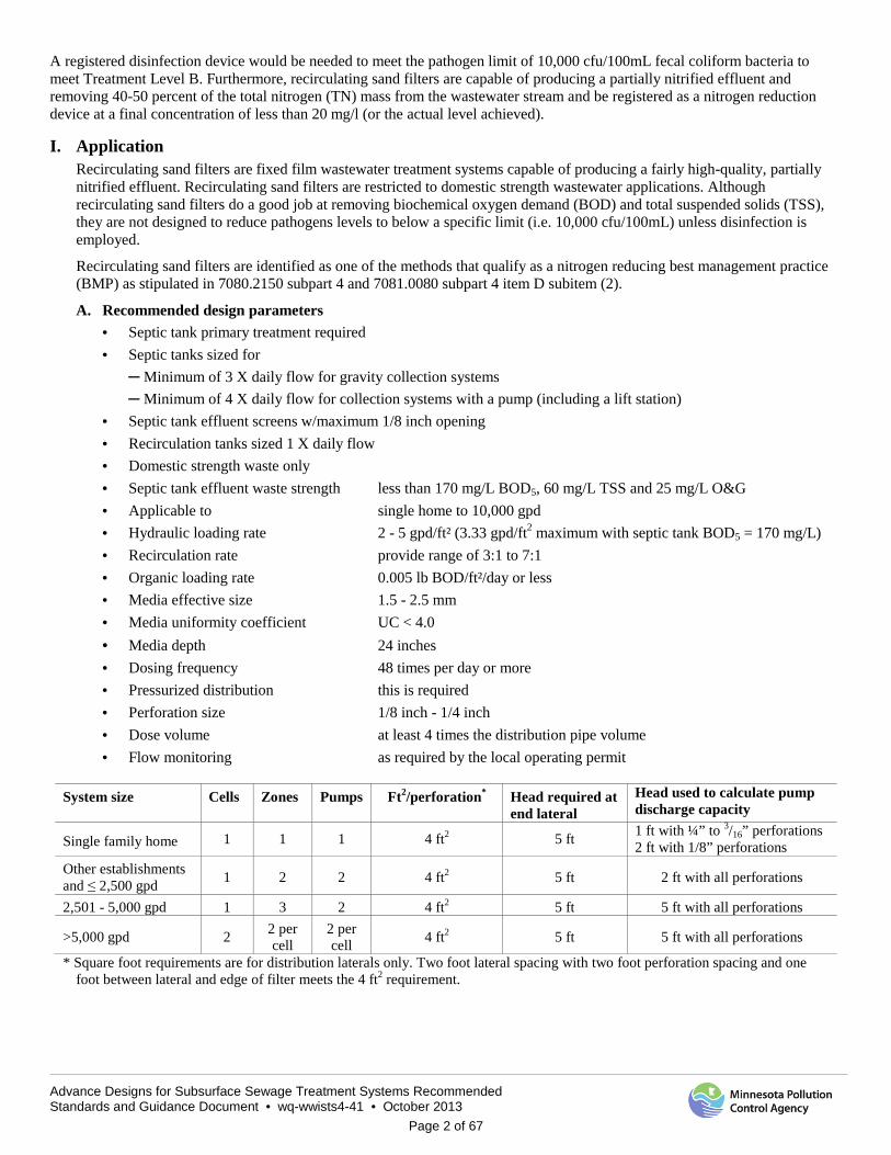
Recirculating Sand Filter How this document is organized Standards section Explanation Page Application Treatment performance, flows and recommended design parameters 2 How to Use this Manual Scope, terminology and abbreviations 3 Background and Process Description Treatment performance, characteristics of recirculating sand filters 4 Design Guidance Process and design requirements, tanks, pumps, sand filter specifications 12 Design Example Provides a step-by-step example in designing a recirculating sand filter 24 Cost Estimating Some considerations in the determination of capital and O&M costs 38 Operation and Maintenance Taking care of the system, system maintenance and monitoring 40 Check Sheet Step-by-step process to check recirculating sand filters 44 References References cited or consulted for this guidance document 48 Appendix A Known limitations in system use 50 Appendix B Regulator construction checklist 51 Appendix C Management plan 52 Appendix D Operating permit example 54 Appendix E Single Pass and Recirculating Sand Filter Worksheet 58 Appendix F Pressure Distribution Design Worksheet 62 Appendix G Pump Selection Design Worksheet 64 Appendix H Pump Tank Design Worksheet 65
Important Note to Users of This Guide This is a guidance document produced by the Minnesota Pollution Control Agency (MPCA) for the benefit of the general public and wastewater treatment professionals alike. It is in no way intended as a substitute for professional engineering consulting advice. While the scenarios described in this document may appear to provide solutions for some situations, users of this guide are strongly recommended to seek the advice of their own consultants and wastewater treatment professionals who can assess the unique circumstances and address the specific concerns and needs of an individual project. The MPCA and its employees accept no responsibility or liability for the contents of this guidance document, the designs or advice contained herein. This guidance document is not intended, and cannot be relied upon, to create any rights, substantive or procedural, that can be enforced in litigation or any administrative proceeding with the State of Minnesota or the MPCA.
This document is the recommended standards and guidance for recirculating sand filters. Recirculating sand filters are public domain treatment technologies (Minn. R. ch. 7083.4000, subp. 1. B.(1).). A public domain treatment technology is a technology developed without a patent. Another example of a public domain material is drainfield rock distribution media. The MPCA considers this recirculating sand filter document to be a registered public domain treatment technology as required in rule.
Systems employing recirculating sand filter (RSF) systems that are designed, installed and operated in accordance with this guidance document are classified as Type IV systems that meet Treatment Level B2 parameters (25 mg/L CBOD5 and 30 mg/L TSS – with no fecal requirement).
Advance Designs for Subsurface Sewage Treatment Systems Recommended Standards and Guidance Document • wq-wwists4-41 • October 2013
Page 2 of 67
A registered disinfection device would be needed to meet the pathogen limit of 10,000 cfu/100mL fecal coliform bacteria to meet Treatment Level B. Furthermore, recirculating sand filters are capable of producing a partially nitrified effluent and removing 40-50 percent of the total nitrogen (TN) mass from the wastewater stream and be registered as a nitrogen reduction device at a final concentration of less than 20 mg/l (or the actual level achieved).
I. Application Recirculating sand filters are fixed film wastewater treatment systems capable of producing a fairly high-quality, partially nitrified effluent. Recirculating sand filters are restricted to domestic strength wastewater applications. Although recirculating sand filters do a good job at removing biochemical oxygen demand (BOD) and total suspended solids (TSS), they are not designed to reduce pathogens levels to below a specific limit (i.e. 10,000 cfu/100mL) unless disinfection is employed.
Recirculating sand filters are identified as one of the methods that qualify as a nitrogen reducing best management practice (BMP) as stipulated in 7080.2150 subpart 4 and 7081.0080 subpart 4 item D subitem (2).
A. Recommended design parameters · Septic tank primary treatment required · Septic tanks sized for
─ Minimum of 3 X daily flow for gravity collection systems ─ Minimum of 4 X daily flow for collection systems with a pump (including a lift station)
· Septic tank effluent screens w/maximum 1/8 inch opening · Recirculation tanks sized 1 X daily flow · Domestic strength waste only · Septic tank effluent waste strength less than 170 mg/L BOD5, 60 mg/L TSS and 25 mg/L O&G · Applicable to single home to 10,000 gpd · Hydraulic loading rate 2 - 5 gpd/ft² (3.33 gpd/ft2 maximum with septic tank BOD5 = 170 mg/L) · Recirculation rate provide range of 3:1 to 7:1 · Organic loading rate 0.005 lb BOD/ft²/day or less · Media effective size 1.5 - 2.5 mm · Media uniformity coefficient UC < 4.0 · Media depth 24 inches · Dosing frequency 48 times per day or more · Pressurized distribution this is required · Perforation size 1/8 inch - 1/4 inch · Dose volume at least 4 times the distribution pipe volume · Flow monitoring as required by the local operating permit
System size Cells Zones Pumps Ft2/perforation* Head required at end lateral
Head used to calculate pump discharge capacity
Single family home 1 1 1 4 ft2 5 ft 1 ft with ¼” to 3/16” perforations 2 ft with 1/8” perforations
Other establishments and ≤ 2,500 gpd 1 2 2 4 ft2 5 ft 2 ft with all perforations
2,501 - 5,000 gpd 1 3 2 4 ft2 5 ft 5 ft with all perforations
>5,000 gpd 2 2 per cell
2 per cell 4 ft2 5 ft 5 ft with all perforations
* Square foot requirements are for distribution laterals only. Two foot lateral spacing with two foot perforation spacing and one foot between lateral and edge of filter meets the 4 ft2 requirement.
Advance Designs for Subsurface Sewage Treatment Systems Recommended Standards and Guidance Document • wq-wwists4-41 • October 2013
Page 3 of 67
II. How to Use This Manual A. Scope
Current rules and regulations do not provide specific technical standards for recirculating sand filters as a wastewater treatment alternative. This manual is intended to provide the design and review process for this technology by: · providing information on the treatment performance, O&M requirements, size, applicability and cost of
recirculating sand filter systems, · acting as a guide to determining the applicability of recirculating sand filters, · advising the designer as to the selection and sensitivity of design parameters, · providing an overview of the design process
The manual has application for: · Treatment of domestic wastewater (sewage) only · Flows between single family home to 10,000 gpd
The following assumptions on wastewater strength have been used throughout the manual: · Effluent from septic tanks with BOD5 of 170 mg/L · Effluent from septic tanks with TSS of 60 mg/L · Effluent from septic tanks with oil and grease of 25 mg/L
This manual is intended for use by intermediate designers (≤2,500 gpd) and advanced designers (2,501 to 10,000 gpd), local permitting authorities, owners, consulting engineers, and MPCA review staff, as well as funding source personnel to provide guidance for the successful design of recirculating sand filters within Minnesota. Nothing within this manual should be construed or viewed as eliminating additional alternative treatment systems, or alternative design approaches with respect to recirculating sand filters.
The design worksheets created by the University of Minnesota Onsite Sewage Treatment Program, in partnership with the MPCA which are presented in this document, which must be utilized by the intermediate or advanced designer to perform the calculations necessary while designing a recirculating sand filter system.
B. Terminology Ammonia - A naturally occurring inorganic form of nitrogen in combination with hydrogen. Total ammonia includes unionized ammonia (NH3) as well as ionized ammonium (NH4
+) the proportion between ionized and unionized ammonia depends on the pH and temperature of the solution. Ammonia is both toxic to aquatic animal life and a source of nutrition to plants. Biochemical Oxygen Demand - The five-day biochemical oxygen demand (BOD5) of domestic wastewater is the measure of the amount of molecular oxygen required to stabilize the decomposable matter present in water by aerobic biochemical action, as determined by a standard laboratory procedure. Denitrification - The process of biologically converting nitrate and nitrite (NO3
- and NO2-) to nitrogen gas.
Filter cell - The total filter area that can be served by a single dosing pump or set of pumps. A filter cell is also separated by a physical barrier such as a liner. Filter zone - The area of a filter cell that can be dosed by a single pumping event. Forward flow - The net daily flow rate into and out of the treatment system; does not include the recirculated flow. Nitrification - The process of biologically oxidizing ammonia (NH4
+ and NH3) to nitrate and nitrate (NO3- and NO2
-). Pathogen - A disease producing microorganism. Recirculation ratio - The ratio of the rate of flow returned to the recirculation tank for additional treatment to the rate of flow discharged as effluent. Sequencing valve - Valve used to automatically direct flow to two or more final treatment and dispersal components, one or more at a time, and in a prescribed order. Total Kjeldahl Nitrogen - The sum of the organic nitrogen and total ammonia nitrogen present. Total Nitrogen - The sum of organic nitrogen, total ammonia nitrogen and nitrate + nitrite nitrogen.
Advance Designs for Subsurface Sewage Treatment Systems Recommended Standards and Guidance Document • wq-wwists4-41 • October 2013
Page 4 of 67
C. Abbreviations of some terms used in this document are as follows: BOD5 BOD5, the five-day biochemical oxygen demand DO dissolved oxygen gpd gallons per day gpd/sf gallons per day per square foot gpm gallons per minute ISTS Individual Subsurface Sewage Treatment Systems mg/L milligrams per liter MPCA Minnesota Pollution Control Agency MSTS Mid-Sized Subsurface Sewage Treatment Systems NH4 ammonia NO3 nitrate P, TP phosphorus, total phosphorus RSF recirculating sand filter STEG Septic Tank Effluent Gravity collection STEP Septic Tank Effluent Pump collection SSTS Subsurface Sewage Treatment Systems TKN total Kjeldahl nitrogen TN total nitrogen TSS total suspended solids
III. Background and Process Description A. Background of recirculating sand and gravel filters
Sand filtration is a term that generally describes an aerobic, fixed-film bio-reactor used to stabilize pre-treated, domestic strength wastewater. Rather than a strictly physical process as implied by the term “filter”, media filtration in this context employs a combination of physical, chemical and biological processes.
The “media” can be any of a number of physical structures which sole purpose is to provide a surface to support biological growth. The category of treatment referred to as sand filtration includes a number of variations on the process. They can be broken down into subcategories based on how many passes through the filter the wastewater makes, whether the filter surface is open to the air or buried, and the relative size and type of the media (sand, gravel, textile or other). This manual will focus on multi-pass or recirculating sand filters.
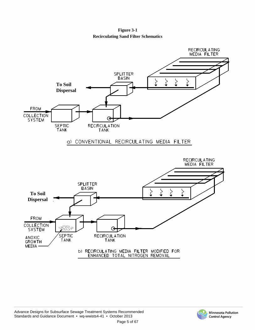
In all cases, primary treatment of the raw sewage is required to reduce suspended solids, oil and grease and possibly some BOD5 content. Once settling is accomplished in the septic tank, the septic tank effluent is applied to the filter surface in small doses, to alternately load and rest the media. As wastewater percolates down through the filter bed, it comes into contact with the bacterial film growing on the media. The filtrate is contained by an impermeable liner, and collected in an underdrain. The underdrain pipe directs the filtrate to a flow splitting structure, in which a portion of the flow can be diverted back to the recirculation tank for additional treatment, with the rest discharged as effluent. Where TN removal is desired, recirculation back through the settling tanks provides contact between the nitrate-laden filtrate and carbon-bearing influent in the presence of bacteria to encourage denitrification.
A schematic of typical sand filtration systems is shown in Figure 3-1.
Advance Designs for Subsurface Sewage Treatment Systems Recommended Standards and Guidance Document • wq-wwists4-41 • October 2013
Page 5 of 67
Figure 3-1 Recirculating Sand Filter Schematics
To Soil Dispersal
To Soil Dispersal

Advance Designs for Subsurface Sewage Treatment Systems Recommended Standards and Guidance Document • wq-wwists4-41 • October 2013
Page 6 of 67
B. Discharge performance capability 1. General
If the parameters of concern are primarily BOD, ammonia and TSS, recirculating sand filters are capable of producing a high quality effluent. The performance of an individual system is influenced by a variety of design and operational issues, each of which will be discussed in this design guidance.
Conventional sand filtration will provide partial-to-full conversion of ammonia-nitrogen to nitrate-nitrogen. Where reduction of all forms of nitrogen (total nitrogen [TN]), including nitrate-nitrogen, ammonia-nitrogen and organic nitrogen) is required, modifications to the conventional process are capable of attaining effluent TN concentrations of 15 to 20 mg/L TN without supplemental carbon addition. By adding an additional carbon source (such as acetic acid, glycol solutions or other proprietary products), numerous studies have demonstrated that effluent nitrogen can be driven to less than 10 mg/L TN.
2. Total nitrogen removal Some areas of the country, including Minnesota, are requiring more strict control of nutrients that can degrade groundwater quality, including nitrate-nitrogen. Reduction of all forms of nitrogen (ammonia, organic, nitrite and nitrate) to a total concentration of less than 10 mg/L TN is becoming a requirement where discharge to groundwater could impact drinking water. In general, recirculating sand filters can be designed to increase their level of nitrogen removal, but they are not likely to reliably produce an effluent with less than 15 to 20 mg/L TN. Additional treatment units or mitigation in the design of the dispersal system will be required to minimize impacts to the ground water.
In order to accomplish a higher level of TN removal biologically, a system must first be able to oxidize ammonia to nitrate in the process of nitrification, described above. After this transformation is complete, a separate species of organisms may be able to utilize the molecularly bound oxygen of nitrate as an electron acceptor for the reduction of nitrate to nitrogen gas, or N2. Once formed, N2 will be liberated into the gaseous phase, thereby completing its removal from the wastewater. This process is referred to as denitrification.
Several conditions are required to be satisfied in order to perform this process. For nitrification to proceed, the wastewater must have sufficient alkalinity to allow the biochemical conversion from ammonia to nitrate to occur. Denitrification requires that anoxic conditions exist, meaning that dissolved oxygen must be effectively absent. In addition, sufficient carbon must be available for cell synthesis, typically at ratios ranging from three to eight pounds of BOD per pound of nitrate-nitrogen.
Denitrification performed in an anoxic zone created, after the initial septic tank and prior to the recirculation tank, is referred to as pre-denitrification. Filtrate is recycled to the anoxic zone instead of the recirculation tank where the nitrate from the filtrate mixes with the available carbon in the influent. Residual dissolved oxygen in the filtrate is quickly depleted, creating anoxic conditions. When sufficient carbon remains, a culture of denitrifying bacteria is favored.
The most basic technique to create this environment is to simply redirect the filtrate to the head end of the septic tank, if the septic tank is near the sand filter. A study by Sack et al (1988) was able to achieve TN removal rates of 83 to 90 percent by employing recycle rates ranging from 10:1 to a high as 28:1. In the case cited in this study, there appears to have been sufficient carbon to allow a high level of TN removal. For community scale systems, these recycle rates are unrealistic, as the pumping energy and capital cost of the pumps and pipes to carry such a high flow will not be cost-effective. High recycle rates may also eliminate or reduce the size of the anoxic zone, thereby reducing or eliminating the pre-denitrification.
The maximum nitrogen removal rate is affected by a number of variables, including the carbon to nitrogen ratio in the anoxic zone. As the recycle rate increases, the ratio of available carbon to nitrate in the anoxic zone decreases. A minimum of 2.5 to 3 pounds of BOD per pound of nitrate-nitrogen is needed for complete denitrification; field experience has shown that this ratio can be as high as eight pounds of BOD per pound of nitrate-nitrogen (Boyle, 1995). In wastes where the influent BOD:TKN ratios are 3:1 or less, such as those from a STEP system, this modification may not successfully allow treatment of TN without the addition of supplemental carbon.
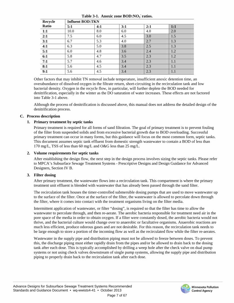
Table 3-1 shows the decrease in the anoxic zone BOD:NO3- ratios in response to increased recycle for varying
influent BOD:TKN ratios. This table shows how increasing the recycle rate to improve TN removal has its limitations, particularly for wastewaters exhibiting influent BOD:TKN ratios of less than 3:1. The shaded areas denote situations in which increasing the recycle ratio is not likely to further improve TN removal.
Advance Designs for Subsurface Sewage Treatment Systems Recommended Standards and Guidance Document • wq-wwists4-41 • October 2013
Page 7 of 67
Table 3-1. Anoxic zone BOD:NO3- ratios.
Recycle Ratio
Influent BOD:TKN 5:1 4:1 3:1 2:1 1:1
1:1 10.0 8.0 6.0 4.0 2.0 2:1 7.5 6.0 4.5 3.0 1.5 3:1 6.7 5.3 4.0 2.7 1.3 4:1 6.3 5.0 3.8 2.5 1.3 5:1 6.0 4.8 3.6 2.4 1.2 6:1 5.8 4.7 3.5 2.3 1.2 7:1 5.7 4.6 3.4 2.3 1.1 8:1 5.6 4.5 3.4 2.3 1.1 9:1 5.6 4.5 3.4 2.3 1.1
Other factors that may inhibit TN removal include temperature, insufficient anoxic detention time, an overabundance of dissolved oxygen in the filtrate return, short-circuiting in the recirculation tank and low bacterial density. Oxygen in the recycle flow, in particular, will further deplete the BOD needed for denitrification, especially in the winter as the DO saturation of water increases. These effects are not factored into Table 3-1 above.
Although the process of denitrification is discussed above, this manual does not address the detailed design of the denitrification process.
C. Process description 1. Primary treatment by septic tanks
Primary treatment is required for all forms of sand filtration. The goal of primary treatment is to prevent fouling of the filter from suspended solids and from excessive bacterial growth due to BOD overloading. Successful primary treatment can occur in many forms, but this guidance will focus on the most common form, septic tanks. This document assumes septic tank effluent from domestic strength wastewater to contain a BOD of less than 170 mg/L, TSS of less than 60 mg/L and O&G less than 25 mg/L.
2. Volume requirements for septic tanks After establishing the design flow, the next step in the design process involves sizing the septic tanks. Please refer to MPCA’s Subsurface Sewage Treatment Systems - Prescriptive Designs and Design Guidance for Advanced Designers, Section IV B.
3. Filter dosing After primary treatment, the wastewater flows into a recirculation tank. This compartment is where the primary treatment unit effluent is blended with wastewater that has already been passed through the sand filter.
The recirculation tank houses the timer-controlled submersible dosing pumps that are used to move wastewater up to the surface of the filter. Once at the surface of the filter, the wastewater is allowed to percolate down through the filter, where it comes into contact with the treatment organisms living on the filter media.
Intermittent application of wastewater, or filter “dosing”, is required so that the filter has time to allow the wastewater to percolate through, and then re-aerate. The aerobic bacteria responsible for treatment need air in the pore space of the media in order to obtain oxygen. If a filter were constantly dosed, the aerobic bacteria would not thrive, and the bacterial culture would change over to anaerobic or facultative organisms. Anaerobic reactions are much less efficient, produce odorous gases and are not desirable. For this reason, the recirculation tank needs to be large enough to store a portion of the incoming flow as well as the recirculated flow while the filter re-aerates.
Wastewater in the supply pipe and distribution piping must not be allowed to freeze between doses. To prevent this, the discharge piping must either rapidly drain from the pipes and/or be allowed to drain back to the dosing tank after each dose. This is typically accomplished by drilling a weep hole after the check valve on dual pump systems or not using check valves downstream of single pump systems, allowing the supply pipe and distribution piping to properly drain back to the recirculation tank after each dose.
Advance Designs for Subsurface Sewage Treatment Systems Recommended Standards and Guidance Document • wq-wwists4-41 • October 2013
Page 8 of 67
4. Filter media, wastewater distribution and cover Media is the material or product used to provide support for the attached microbial growth that will provide the aerobic biological treatment. It is not, as the name might imply, used primarily to provide physical filtration of influent solids, although some filtration does occur. Media is among the most important elements of a recirculating sand filtration system, and is among the most costly.
The difference between a recirculating sand filter and a recirculating gravel filter (RGF) is largely a matter of semantics. Although gravel implies a coarser filter media than sand, the typical gravel and sand filter media are very similar. Geologists use the Krumbein or Wentworth scales to define classes of soil grains by size. Under these scales, sand refers to particle sizes up to 2 mm and gravel refers to particles larger than 2 mm. For the purposes of this document, recirculating sand filter media will refer to media having an Effective Size, or D10 (the diameter at which ten percent of the material by weight is finer) of up to 2 mm, and recirculating gravel filters will refer to media having a D10 larger than 2 mm. Most of the media in use falls near to the 2 mm dividing line between sand and gravel, and includes particle sizes both above and below this size.
An ideal media will have the following properties: a) High surface area to volume ratio b) Large enough voids to allow for rapid air infiltration and to minimize fouling c) Good weathering properties, including
i. Ultraviolet (UV) resistance if exposed to sunlight ii. Physical wear and soundness
iii. Low solubility in water and acidic conditions d) Be cost-effective and locally available e) Grain size
Some of the earliest work on recirculating sand filtration was performed by Hines and Favreau in the 1970’s using sand media having a D10 of 0.3 mm (Loudon, 1984). A variety of studies comparing treatment performance and fouling of media for varying effective size have followed, and include Sauer, 1976; Boyle, 1995; Darby et al, 1996; and Zaplatikova et al, 2006. In general, these studies have found that media size has the greatest impact on performance for single pass and infrequently dosed filters. In these cases, fine-grained media (0.25 – 0.3 mm) will provide better treatment than coarser media due to the high surface area to volume property of fine-grained soils. This difference in performance was reduced by increasing dosing frequency and by providing recirculation. Once it was demonstrated that similar performance could be expected from a variety of media sizes, media selection became based more on extending the longevity of a filter run and minimizing maintenance than on treatment performance.
f) Uniformity The other key characteristic of granular media is its uniformity. To prevent the accumulation of smaller particles within the void spaces of larger particles, which would lead to clogging of the filter, the research has recommended a relatively uniform, or poorly sorted, media. The degree of uniformity is described by the Uniformity Coefficient (UC), which is the ratio of the D60 to D10. The lower this number, the more uniform the media. The highest allowed UC is typically 4.0, with many specifications requiring a UC of 2.5 or less. In general, the lower the uniformity coefficient, the less prone to fouling the media will be, but the cost of the media will likely increase due to the additional volume of raw material that must be screened to manufacture the media.
g) Depth Much of the earlier guidance on single pass sand filters suggested a media depth of 36 inches or more. More recent research has found that less depth is necessary (Anderson, 1985; Darby, 1996). The majority of the biological activity has been found to occur in the upper nine to 12 inches of the bed (Anderson, 1985). Darby (1996) reported results using a filter depth of 15 inches that were comparable to those from previous studies using deeper filter beds. As sand media is one of the more expensive elements of a sand filtration system, any ability to safely minimize the quantity will result in significant cost savings. Based on these studies, a filter bed depth of 24 inches has been commonly used in Wisconsin, Massachusetts, Rhode Island and other states. It provides for some safety factor, and would allow for removal of several inches of fouled media, if necessary, without replacement.
Advance Designs for Subsurface Sewage Treatment Systems Recommended Standards and Guidance Document • wq-wwists4-41 • October 2013
Page 9 of 67
h) Selection Virtually any granular media will successfully support biological growth that will treat wastewater with some degree of success. There is no one right size and gradation. All, however, offer tradeoffs, and it is the role of the designer to select the best fit for a particular application.
The following general relationships with respect to media size have emerged as a result of much research and actual experience. These relationships apply to granular media between 0.3 mm and 5 mm in size.
As media size increases i. Time to fouling increases
ii. Maintenance decreases iii. Allowable hydraulic loading rate increases (filter area becomes smaller) iv. Media life may be extended v. Less prone to freezing
But: i. Higher recycle rates may be necessary, resulting in greater power consumption
ii. Better distribution of wastewater may be necessary i) Wastewater distribution
Once a media size and gradation have been selected, the designer must apply a method of distributing the wastewater over the media that is appropriate for that media. Distribution is frequently accomplished by a network of perforated plastic pipe laid on the surface of the filter media and embedded in a layer of coarse stone. The pipes convey wastewater pumped by the dosing pumps and distributes it to the filter surface. Wastewater is then applied to the filter surface through a series of perforations, or holes drilled of a specific size in the pipe.
j) Media cover The media used for the distribution of the wastewater over the filter shall not be covered with any type of material. This rock layer must be left open to the atmosphere to allow for the transfer of oxygen to the filter. The rock layer above the distribution network provides: 1) an air gap for frost protection and 2) a cover material to limit human contact with the effluent.
5. Liner and underdrain All recirculating sand filters must have an impervious bottom and sides so that partially treated wastewater is collected and does not escape. Single family sand filters are sometimes constructed in concrete tanks, but community scale filters typically use earthen sidewalls with a synthetic liner placed at the bottom and up the sides. The liner material most commonly used is 30-mil PVC. Refer to the MPCA guidance on synthetic liner installation at:
High Density Polyethylene (HDPE) liners
http://www.pca.state.mn.us/publications/wq-wwtp5-32.pdf
Polyvinyl Chloride (PVC) liners
http://www.pca.state.mn.us/publications/wq-wwtp5-60.pdf
Perforated collection pipe laid on top of the liner is typically used to convey filtrate which collects on the liner back to the recirculation tank. The underdrain pipe is typically vented to the surface to allow air in, and is often bedded in clean stone of larger diameter than the sand filter media. The underdrain media should be large enough to not blind the underdrain pipe openings (which would impede drainage from the sand filter), and should be sized to support the overlying treatment media. Geotextile fabric is recommended to be laid under the liner and between the liner and underdrain media. Geotextile fabric must not be placed between layers of media or around the underdrain piping. Early designs using geotextile fabric to separate media layers exhibited high rates of failure due to fouling of the geotextile fabric itself.

Advance Designs for Subsurface Sewage Treatment Systems Recommended Standards and Guidance Document • wq-wwists4-41 • October 2013
Page 10 of 67
6. Flow splitting and recirculation Recirculation is one of the primary controls, used by the designer and service provider, to control the degree of wastewater treatment. Additional treatment can be obtained by recirculating the filtrate back to the recirculation tank, from which it will make an additional pass through the filter. The portion of the flow routed back to the recirculation tank relative to that portion of the flow discharged as effluent is quantified as the recirculation ratio (R). Recirculation ratios typically range between 3:1 and 7:1, with 4:1 being typical. Figure 3-2 illustrates this concept for a recirculation ratio, R = 4:1, or simply 4.
Figure 3-2
Recirculation Ratio
Each pass through the filter media provides additional contact time with the treatment organisms and results in a higher degree of treatment. The total number of passes through a filter is determined by the recirculation ratio, R, and is equal to R+1. While a higher recycle ratio generally provides better treatment, it requires more energy to pump the wastewater through the filter each additional time. Once the system is in operation, the service provider, in consultation with the designer, may make adjustments to the recirculation ratio to determine the best balance between reliable treatment (more recycle) and efficient operation (less recycle).
There can also be harmful effects if the recirculation ratios exceed 7:1 or 8:1. High recycle rates can deplete alkalinity due to complete nitrification and drive pH below acceptable levels. Low pH can allow filamentous organisms to form and clog distribution perforations. Alkalinity may need to be added in cases where low pH affects the operation or performance of the filter.
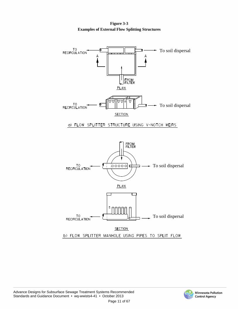
Control over the recycle rate is done using a flow splitting structure or valve located between the sand filter and dosing tank. The ideal flow splitter will give the service provider the ability to determine the recirculation ratio, and thus be able to exercise some control over the degree of treatment and energy demand. For large flow applications, flow splitting can be accomplished with weirs or overflow pipes as shown in Figure 3-3.
1Q TO SOIL DISPERSAL
Advance Designs for Subsurface Sewage Treatment Systems Recommended Standards and Guidance Document • wq-wwists4-41 • October 2013
Page 11 of 67
Figure 3-3 Examples of External Flow Splitting Structures
To soil dispersal
To soil dispersal
To soil dispersal
To soil dispersal

Advance Designs for Subsurface Sewage Treatment Systems Recommended Standards and Guidance Document • wq-wwists4-41 • October 2013
Page 12 of 67
Another type of flow splitter is the recirculating splitter valve shown in Figure 3-4.
Figure 3-4 Recirculating Splitter Valve (Ball and Denn, 1997)
IV. Design Guidance As can be seen from the preceding sections, there are numerous variations on recirculating sand filtration systems, all of which can be successful, but all of which also offer some trade-offs. No single filter design or operating parameter was found to adequately predict the performance of sand filters (Darby, 1996).
This design guidance will focus on one of numerous potential design approaches that are commonly used for small facilities. The design examples that follow will utilize this method and alternate approaches are outside the scope of this document.
A. Design process overview The general process used by this manual to design a recirculating sand filter will be in accordance with the following steps:
1. Determine design requirements a) Characterize design flow rates b) Characterize influent wastewater makeup c) Determine effluent soil dispersal location and limits
2. Size primary treatment unit a) Septic tank size, number and layout b) Tank configuration c) Effluent screens and alarm
3. Size recirculation tank 4. Size sand filter and distribution system
a) Select hydraulic and organic loading rates b) Determine filter size c) Determine optimal filter layout
i. Length ii. Width
iii. Lateral and perforation spacing
Advance Designs for Subsurface Sewage Treatment Systems Recommended Standards and Guidance Document • wq-wwists4-41 • October 2013
Page 13 of 67
iv. Select head and associated perforation discharge v. Calculate required pump flow rate
vi. Determine number of cells vii. Determine number of zones
d) Select media gradation e) Select media depth
5. Size dosing pumps and controls a) Select range of recirculation ratios b) Select nominal pump size c) Determine number of pumps needed d) Provide service provider with recommendations on pump cycle times, dose volumes and frequency based on
flow, wastewater strength and system performance 6. Determine size, number, and location of filter underdrain collectors
a) Select liner material b) Select number, size and type of underdrains c) Select drain perforation size, shape, location on the pipe and spacing d) Select underdrain bedding media gradation and depth
7. Size flow splitter elements a) Size recirculation pipe to splitter b) Determine type of flow splitter c) Size splitter elements
8. Size downstream elements a) Disinfection (if applicable) b) Soil treatment and dispersal system
9. Determine hydraulic profile and set elevations In addition to providing guidelines for the design of a recirculating sand filter, a set of default design parameters will be given in each section for single family homes to clusters of residential developments with flow rates ranging from single family home to 10,000 gallons per day (gpd).
B. Design requirements 1. Design flow
Use MPCA/University of Minnesota Design Flow Worksheet to determine the design flow.
2. Wastewater loadings Recirculating sand filter systems are intended for the treatment of domestic wastewaters. High strength residential and commercial or industrial wastewaters are not appropriate for treatment in a recirculating sand filter since the filter will be susceptible to biological clogging. Typical domestic wastewater strength parameters should be used to characterize the strength of the wastewater to be treated. Table 4-1 contains typical influent wastewater characteristics, as well as settled wastewater that is representative of a community-scale septic tank, and for influent wastewater from a STEP/STEG collection system.
Table 4-1. Typical domestic wastewater strength, concentrations in mg/L.
Parameter Influent Community Septic Tank Effluent STEP/STEG Effluent BOD 300 170 170 TSS 200 60 60 TKN 50 50 50
Alkalinity Varies 50 - 350
Advance Designs for Subsurface Sewage Treatment Systems Recommended Standards and Guidance Document • wq-wwists4-41 • October 2013
Page 14 of 67
A pH between 7.2 and 9.0 is optimal for nitrification. The oxidation of ammonia consumes alkalinity at a rate of 7.14 mg/L alkalinity as CaCO3 per mg/L of ammonia. Depletion of alkalinity may depress pH, which could in turn inhibit nitrification. The designer of a facility with an effluent limit for nitrogen will need to consider whether sufficient alkalinity is present in the wastewater for nitrification to occur.
Nitrogen is sometimes expressed as Total Kjeldahl Nitrogen (TKN) which is the sum of ammonia plus organic nitrogen. This form of nitrogen should be used, when possible, when characterizing influent strength because much of the organic fraction will convert to ammonia in the preliminary treatment phase, and better represents the total amount of ammonia the treatment system will ultimately need to treat.
3. Treatment goals The degree of treatment required is driven by geologic and soil conditions at the site. The treatment goals are determined in accordance with the environmental protection standards of Minn. R. ch.7080. For mid-sized subsurface sewage treatment systems (MSTS) regulated under Minn. R. ch. 7081, the treatment goals are determined in accordance with the environmental protection standards of Minn. R. ch. 7081. SSTS may be subject to a TN standard of 10 mg/L if located in a nitrogen sensitive area. The designer shall complete the nitrogen worksheet in Section II F in Prescriptive Designs and Design Guidance for Advanced Designers to determine what limits may be applicable.
Recirculating sand filters designed, installed and operating in accordance with this guidance are a Type IV system capable of meeting Treatment Level B2 wastewater parameters. Treatment technologies that meet Level B2 are capable of producing an effluent with less than CBOD5 of 25 mg/L and TSS of 30mg/L (with no limit for fecal coliform bacteria). A separate disinfection process would be needed to meet Treatment Level B fecal coliform bacteria limits (less than 10,000 cfu/100mL). Although TN removal rates are variable, recirculating filters can remove 40 to 50 percent of the TN from the wastewater stream (Crites and Tchobanoglous, 1998).
C. Primary treatment units 1. Septic tank sizing
a) STEP systems Individual septic tanks in STEP/STEG collection system should be sized in accordance with the requirements in Sections IV. B. and V of the MPCA document of Prescriptive Designs and Design Guidance for Advanced Designers.
b) Community scale septic tanks Sizing of community septic tanks shall follow the sizing required in Section IV. B in the MPCA document Subsurface Sewage Treatment Systems Prescriptive Designs and Design Guidance for Advanced Designers.
2. Effluent screens Effluent screens must be installed in the final septic tank to: 1) help to reduce large particles and scum from the septic tank and plugging the sand filter, and 2) help to minimize plugging of the distribution perforations and media. Effluent screens must be sized smaller than the pressure distribution perforation diameter. All effluent screens must be equipped with a high water alarm.
D. Recirculation tank At a minimum, the recirculation tank should be sized for one day’s average forward flow.
E. Sand filter 1. Loading rate selection
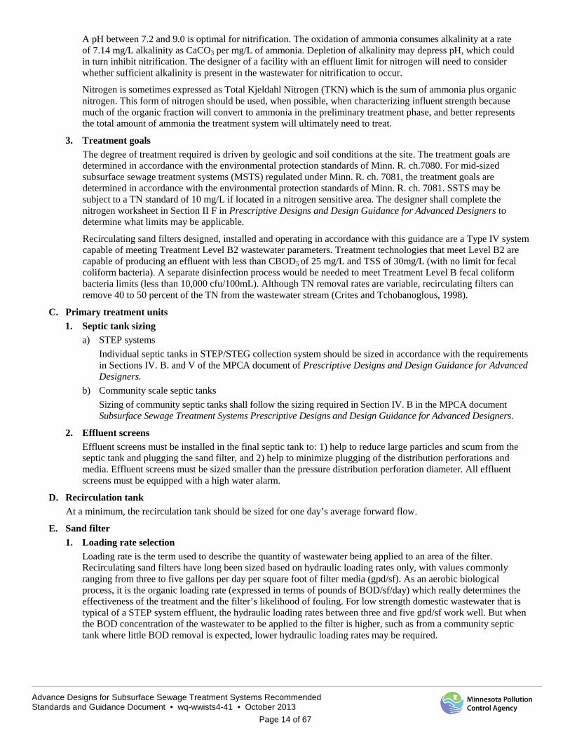
Loading rate is the term used to describe the quantity of wastewater being applied to an area of the filter. Recirculating sand filters have long been sized based on hydraulic loading rates only, with values commonly ranging from three to five gallons per day per square foot of filter media (gpd/sf). As an aerobic biological process, it is the organic loading rate (expressed in terms of pounds of BOD/sf/day) which really determines the effectiveness of the treatment and the filter’s likelihood of fouling. For low strength domestic wastewater that is typical of a STEP system effluent, the hydraulic loading rates between three and five gpd/sf work well. But when the BOD concentration of the wastewater to be applied to the filter is higher, such as from a community septic tank where little BOD removal is expected, lower hydraulic loading rates may be required.
Advance Designs for Subsurface Sewage Treatment Systems Recommended Standards and Guidance Document • wq-wwists4-41 • October 2013
Page 15 of 67
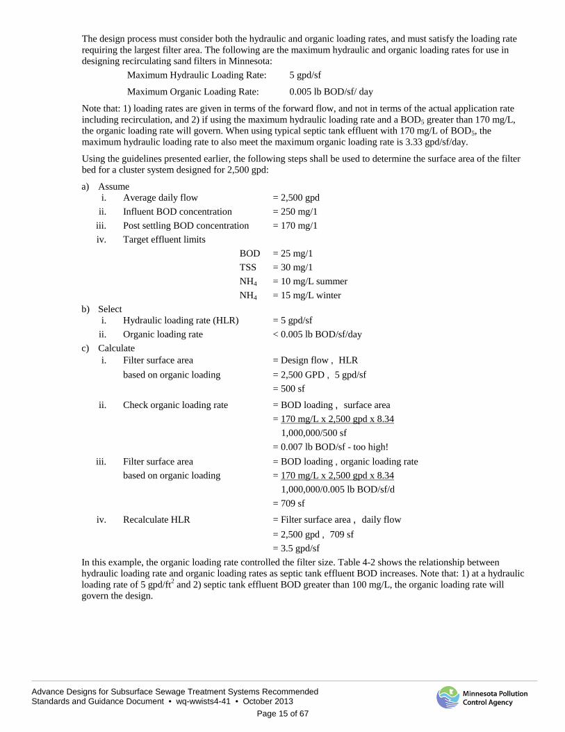
The design process must consider both the hydraulic and organic loading rates, and must satisfy the loading rate requiring the largest filter area. The following are the maximum hydraulic and organic loading rates for use in designing recirculating sand filters in Minnesota:
Maximum Hydraulic Loading Rate: 5 gpd/sf
Maximum Organic Loading Rate: 0.005 lb BOD/sf/ day
Note that: 1) loading rates are given in terms of the forward flow, and not in terms of the actual application rate including recirculation, and 2) if using the maximum hydraulic loading rate and a BOD5 greater than 170 mg/L, the organic loading rate will govern. When using typical septic tank effluent with 170 mg/L of BOD5, the maximum hydraulic loading rate to also meet the maximum organic loading rate is 3.33 gpd/sf/day.
Using the guidelines presented earlier, the following steps shall be used to determine the surface area of the filter bed for a cluster system designed for 2,500 gpd:
a) Assume i. Average daily flow = 2,500 gpd
ii. Influent BOD concentration = 250 mg/1 iii. Post settling BOD concentration = 170 mg/1 iv. Target effluent limits
BOD = 25 mg/1 TSS = 30 mg/1 NH4 = 10 mg/L summer NH4 = 15 mg/L winter
b) Select i. Hydraulic loading rate (HLR) = 5 gpd/sf
ii. Organic loading rate < 0.005 lb BOD/sf/day c) Calculate
i. Filter surface area = Design flow ¸ HLR based on organic loading = 2,500 GPD ¸ 5 gpd/sf
= 500 sf
ii. Check organic loading rate = BOD loading ¸ surface area = 170 mg/L x 2,500 gpd x 8.34
1,000,000/500 sf = 0.007 lb BOD/sf - too high!
iii. Filter surface area = BOD loading ¸organic loading rate based on organic loading = 170 mg/L x 2,500 gpd x 8.34
1,000,000/0.005 lb BOD/sf/d = 709 sf
iv. Recalculate HLR = Filter surface area ¸ daily flow = 2,500 gpd ¸ 709 sf = 3.5 gpd/sf
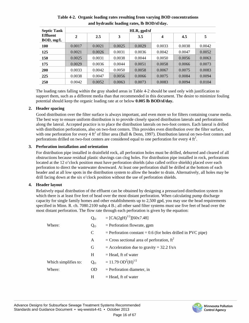
In this example, the organic loading rate controlled the filter size. Table 4-2 shows the relationship between hydraulic loading rate and organic loading rates as septic tank effluent BOD increases. Note that: 1) at a hydraulic loading rate of 5 gpd/ft2 and 2) septic tank effluent BOD greater than 100 mg/L, the organic loading rate will govern the design.
Advance Designs for Subsurface Sewage Treatment Systems Recommended Standards and Guidance Document • wq-wwists4-41 • October 2013
Page 16 of 67
Table 4-2. Organic loading rates resulting from varying BOD concentrations and hydraulic loading rates, lb BOD/sf/day.
Septic Tank Effluent BOD, mg/L
HLR, gpd/sf 2 2.5 3 3.5 4 4.5 5
100 0.0017 0.0021 0.0025 0.0029 0.0033 0.0038 0.0042 125 0.0021 0.0026 0.0031 0.0036 0.0042 0.0047 0.0052 150 0.0025 0.0031 0.0038 0.0044 0.0050 0.0056 0.0063 175 0.0029 0.0036 0.0044 0.0051 0.0058 0.0066 0.0073 200 0.0033 0.0042 0.0050 0.0058 0.0067 0.0075 0.0083 225 0.0038 0.0047 0.0056 0.0066 0.0075 0.0084 0.0094 250 0.0042 0.0052 0.0063 0.0073 0.0083 0.0094 0.0104
The loading rates falling within the gray shaded areas in Table 4-2 should be used only with justification to support them, such as a different media than that recommended in this document. The desire to minimize fouling potential should keep the organic loading rate at or below 0.005 lb BOD/sf/day.
2. Header spacing Good distribution over the filter surface is always important, and even more so for filters containing coarse media. The best way to ensure uniform distribution is to provide closely spaced distribution laterals and perforations along the lateral. Accepted practice is to place the distribution laterals on two-foot centers. Each lateral is drilled with distribution perforations, also on two-foot centers. This provides even distribution over the filter surface, with one perforation for every 4 ft2 of filter area (Ball & Denn, 1997). Distribution lateral on two-foot centers and perforations drilled on two-foot centers are considered equal to one perforation for every 4 ft2.
3. Perforation installation and orientation For distribution pipe installed in drainfield rock, all perforation holes must be drilled, deburred and cleared of all obstructions because residual plastic shavings can clog holes. For distribution pipe installed in rock, perforations located at the 12 o’clock position must have perforation shields (also called orifice shields) placed over each perforation to direct the wastewater downward. At least one perforation shall be drilled at the bottom of each header and at all low spots in the distribution system to allow the header to drain. Alternatively, all holes may be drill facing down at the six o’clock position without the use of perforation shields.
4. Header layout Relatively equal distribution of the effluent can be obtained by designing a pressurized distribution system in which there is at least five feet of head over the most distant perforation. When calculating pump discharge capacity for single family homes and other establishments up to 2,500 gpd, you may use the head requirements specified in Minn. R. ch. 7080.2100 subp.4 B.; all other sand filter systems must use five feet of head over the most distant perforation. The flow rate through each perforation is given by the equation:
QO = [CA(2gH)1/2][60x7.48]
Where: QO = Perforation flowrate, gpm
C = Perforation constant = 0.6 (for holes drilled in PVC pipe)
A = Cross sectional area of perforation, ft2
G = Acceleration due to gravity = 32.2 f/s/s
H = Head, ft of water
Which simplifies to: QO = 11.79 OD2(H)1/2
Where: OD = Perforation diameter, in
H = Head, ft of water
Advance Designs for Subsurface Sewage Treatment Systems Recommended Standards and Guidance Document • wq-wwists4-41 • October 2013
Page 17 of 67
For a residual head H of five feet and a 1/8 inch diameter perforation with area A = 8.52x10⁻⁵ ft2, the flow per perforation is 0.41 gallons per minute (gpm). Good distribution of flow requires that the flow from all perforations be nearly the same. Pressure loss should be minimized such that the difference in flow from the first to the last perforation on a header is less than ten percent. For maximum number of perforations per lateral, see Minn. R. ch. 7080.2050 Subp. 4. E. Table VI. In order to meet dosing requirement, consider using pipe and perforation sizing that is on the small end of the table.
The actual operating head of the completed installation can be measured in the field by opening a terminal valve on each distribution lateral, and measuring the squirt height. The initial clean quirt height should be recorded in the O&M manual to allow comparison in the future. All distribution laterals must have a terminal/flushing valve which allows laterals to be flushed or even jetted.
The header layout and size of the perforations will determine the pumping rate. While designing the header layout and sizing the perforations, the pumping rates shall be kept to a minimum. Large capacity pumps will produce large head requirements and become unmanageable for the service provider.
Selection of the recirculation ratio is then required in order to proceed with the hydraulic design of the header system and final selection of the pump. The designer shall use head loss tables and perform calculations as necessary to size the piping between the pumps and the filter bed to verify that the selected pump will deliver the desired flow at the specified total dynamic head condition. The pump selection design worksheet will assist in these calculations.
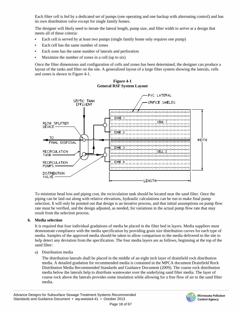
5. Sand filter layout The filter area is divided in to zones and cells. A filter zone is the area that can be dosed by a single dosing pump at any one time. It is determined by the pump size, lateral length, perforation size and perforation spacing. A filter cell is the total filter area that can be served by a single dosing pump or set of pumps. A filter cell can consist of up to six zones, with each zone being dosed in sequence by the dosing pump for that cell. A sequencing valve, or pumps dedicated to each zone, can be used to control which zone is being dosed at any one time. A generalized layout of the filter system, showing the laterals, cells and zones, is shown in Figure 4-1.
Filter layout minimum requirement are as follows: 1) for single family homes one cell with one zone and one pump would be the minimum requirements; 2) for Other Establishments, and flows up to 2,500 gpd, one cell with two zones and two pumps is required; 3) for flows of 2,500 to 5,000 gpd, one cell with at least three zones and two available pumps per zone is required; and 4) for flows over 5,000 gpd, two cells with at least two zones per cell and two separate pumps for each cell (minimum of four pumps) is required. By using sequencing valves, each pair of pumps can serve several zones. As an alternative to sequencing valves for systems that use three or more zones, a dedicated pump for each zone is allowed (one pump per zone).
There is some flexibility as to the layout of the filter. Site constraints may dictate the length to width ratio. The optimum layout of the overall filter is a square, as liner and perimeter wall material are minimized. In actuality, though, the designer will have to iterate length and width to accommodate lateral spacing and to limit the length of the filter to one that will minimize pressure losses. The length of the filter is limited by the ability to maintain a relatively equal head pressure over the perforations.
As an example for one inch diameter PVC laterals with 1/8 inch perforation, this distance is limited to 40 ft. between the first and last perforation. With one foot of clearance on either end, this sets a maximum filter length of 42 ft. Therefore, the filter simply grows wider as the design flow increases (note: changing the pipe diameter or the perforation diameter will result in different maximum filter length). Using this limitation along with the site constraints, the designer selects a filter length and width that will provide the required area. Selection of an even footage for width will allow for easier division into cells and zones of equal size.
Once the filter dimensions have been selected, the number of laterals and individual zones can be determined. Allowing for one foot of clearance from the distant perforation on each end, the lateral length (distance between first and last perforation) will be two feet less than the length of the filter.
The designer must next determine how many zones can be served by a single pump. Multiple zones can be served from a single pump by the use of an automatic distribution valve, or each zone can be served by a dedicated pump. To avoid disabling an entire filter due to the failure of an automatic distribution valve and for many other reasons of service, the total required filter area should be divided into at least two filter cells for flows greater than 5,000 gpd.
Advance Designs for Subsurface Sewage Treatment Systems Recommended Standards and Guidance Document • wq-wwists4-41 • October 2013
Page 18 of 67
Each filter cell is fed by a dedicated set of pumps (one operating and one backup with alternating control) and has its own distribution valve except for single family homes.
The designer will likely need to iterate the lateral length, pump size, and filter width to arrive at a design that meets all of these criteria: · Each cell is served by at least two pumps (single family home only requires one pump) · Each cell has the same number of zones · Each zone has the same number of laterals and perforation · Maximize the number of zones in a cell (up to six)
Once the filter dimensions and configuration of cells and zones has been determined, the designer can produce a layout of the tanks and filter on the site. A generalized layout of a large filter system showing the laterals, cells and zones is shown in Figure 4-1.
Figure 4-1 General RSF System Layout
To minimize head loss and piping cost, the recirculation tank should be located near the sand filter. Once the piping can be laid out along with relative elevations, hydraulic calculations can be run to make final pump selection. It will only be pointed out that design is an iterative process, and that initial assumptions on pump flow rate must be verified, and the design adjusted, as needed, for variations in the actual pump flow rate that may result from the selection process.
6. Media selection It is required that four individual gradations of media be placed in the filter bed in layers. Media suppliers must demonstrate compliance with the media specification by providing grain size distribution curves for each type of media. Samples of the approved media should be taken to allow comparison to the media delivered to the site to help detect any deviation from the specification. The four media layers are as follows, beginning at the top of the sand filter:
a) Distribution media The distribution laterals shall be placed in the middle of an eight inch layer of drainfield rock distribution media. A detailed gradation for recommended media is contained in the MPCA document Drainfield Rock Distribution Media Recommended Standards and Guidance Document (2009). The coarse rock distribution media below the laterals help to distribute wastewater over the underlying sand filter media. The layer of coarse rock above the laterals provides some insulation while allowing for a free flow of air to the sand filter media.
Advance Designs for Subsurface Sewage Treatment Systems Recommended Standards and Guidance Document • wq-wwists4-41 • October 2013
Page 19 of 67
Distribution media registered through the Product Registration Process for use in recirculating sand filters can be used in place of the drainfield rock distribution media.
b) Filter media The depth of the fine filtering media must be 24 inches at a minimum. A depth of greater than 24 inches is allowable but increased media depth has not been shown to be a significant benefit. As the depth of the sand filter media increases, the ability to transfer oxygen to the lower levels decreases. Filter media for recirculating filters must be clean, hard, durable particles that are free from dirt and organic materials. The media must conform to the following requirements:
Effective size (D10) = 1.5 – 2.5 mm Uniformity coefficient (UC) = 4.0 or less Maximum particle size < 3/8 inch Solubility < 5% in acid for particles < No.8 Grain size distribution:
Sieve Size Passing by Weight 3/8 inch 100% No. 4 70-100% No. 8 5-78% No. 10 0-10% No. 200 0-5%
c) Underdrain media Filter underdrain pipes shall be bedded in a coarse media to allow the partially treated wastewater to flow to the underdrain collection pipes. The coarse underdrain media shall be of sufficient size to support the overlying sand filter media without migration of the sand into the coarse media. The underdrain media must be clean, hard, durable stone. The media must be deep enough to cover the underdrain pipes; where four inch diameter underdrains are used, a coarse media depth of six inches is required. An intermediate layer (pea gravel) of two inches must be placed between the coarse underdrain media and the sand filter media to prevent migration of finer media into the lower layer. The coarse underdrain media must be a total of 12 inches in depth, and consist of two layers, each with the following properties:
i. The lower underdrain media surrounding the collection pipe must meet the MPCA document Drainfield Rock Distribution Media Recommended Standards and Guidance Document.
ii. The upper two inches between the coarse underdrain media and the sand filter media must meet the following grain size distribution per ASTM No. 8:
Grain size distribution: Sieve Size Passing by Weight ½ inch 100% 3/8 inch 50-100% No. 4 6-84% No. 8 0-24% No. 16 0-1%
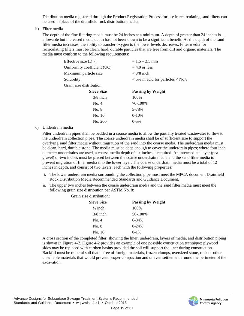
A cross section of the completed filter, showing the liner, underdrain, layers of media, and distribution piping is shown in Figure 4-2. Figure 4-2 provides an example of one possible construction technique; plywood sides may be replaced with earthen basins provided the soil will support the liner during construction. Backfill must be mineral soil that is free of foreign materials, frozen clumps, oversized stone, rock or other unsuitable materials that would prevent proper compaction and uneven settlement around the perimeter of the excavation.
Advance Designs for Subsurface Sewage Treatment Systems Recommended Standards and Guidance Document • wq-wwists4-41 • October 2013
Page 20 of 67
Figure 4-2 Cross Section of a Recirculating Sand Filter
7. Filter underdrain
The job of the filter underdrain is to convey water from the bottom of the filter to the effluent dispersal system, and to provide a conduit for air flow into the bottom of the filter. The underdrain must be vented to the atmosphere to allow entry of air into the underdrain system. The underdrain must be sufficiently sized so that water does not back up into the filter media, which can lead to anaerobic conditions. The openings in the underdrain pipe must be large enough to allow water to enter freely, while preventing the underdrain bedding media from blocking the openings or entering the pipe. The filter bottom must be sloped at least one percent to the underdrain pipe in synthetically lined sand filters.
Slotted PVC pipe is commonly used, with ¼ inch wide slots on four inch centers. Alternatively, corrugated HDPE drain pipe has also been used with success. A minimum of one underdrain, per filter zone, should be provided. The upstream end of the underdrain should be directed up, with two 45 degree bends, and be terminated above the sand filter surface to provide access for cleaning. One underdraim pipe is required in each zone with a maximum spacing of 20 feet.
Advance Designs for Subsurface Sewage Treatment Systems Recommended Standards and Guidance Document • wq-wwists4-41 • October 2013
Page 21 of 67
8. Inspection pipes A total of three inspection pipes should be placed in the filter cells at the following locations and depths: a) Just above the synthetic liner, with perforations that span the depth of the underdrain rock, typically a depth
of 12 inches b) At the bottom of the sand media, with perforations that span six to eight inches of the lower portion of the
sand filter media c) At the top of the sand media, with perforations that span the depth of rock at and below the distribution
network, typically a depth of three to four inches Inspection pipes typically consist of short lengths of four inch PVC pipe that are capped above the filter surface and open at the bottom. The inspections pipes allow for the monitoring of ponding levels at different depths in the sand filter. This, coupled with observations made from cleanouts at the end of the underdrain network, allows access to determine if biological clogging is occurring. For larger systems, multiple sets of inspection pipes are typically needed to monitor ponding at different locations in the system.
The bottom of the inspection pipe should be fitted with an elbow, tee or cross to secure the pipe at the appropriate depth, and to prevent it from being pulled out of the filter media.
Providing the service provider with these observation access points into the filter can help avert a catastrophic clogging incident by being able to see a problem starting and then determining the cause before it becomes a major problem.
9. Filter liner An impervious liner is required to contain the filtrate and allow it to be collected for final dispersal. 30 mil PVC is often used for this purpose. Refer to MPCA synthetic liner guidance for design and construction requirements at:
High Density Polyethylene (HDPE) liners
http://www.pca.state.mn.us/publications/wq-wwtp5-32.pdf Polyvinyl Chloride (PVC) liners
http://www.pca.state.mn.us/publications/wq-wwtp5-60.pdf
The liner must be water tight; this is defined as maintaining water for 24 hours with a loss of less than 1/16 inch. A 24 hour water balance must be performed on all liner installations. The water balance must be preformed after the underdrain pipe and underdrain media has been placed in the filter. The water level during the test must be above any liner penetrations in the underdrain system and above the underdrain media. The water balance may be performed once the filter is complete.
No field seams will be allowed. Geotextile fabric may be needed on top of liner, according to MPCA’s synthetic liner guidance documents, to prevent the liner from being punctured. Geotextile fabric should only be used to protect the liner; use of fabric between layers of media must not be used because of exhibited high rates of failure due to fouling. Pipe penetrations must use a watertight boot connection; they must also be inspected at the time of installation. To ensure material compatibility, liner material must conform to MPCA synthetic liner recommendations. Additional requirements are found in the MPCA PVC and HDPE Liner Guidelines Items 1 and 2 in the general part of the liner installation section do not apply to the PVC guidance. Items 1, 2, and 3 in the general part of the installation section do not apply for the HDPE guidance.
The excavation sidewalls are often ½ inch to ¾ inch untreated plywood or Oriented Strand Board (OSB). The liner is lapped over the sidewalls at least 18 inches and the space between the excavation and OSB is typically backfilled with sand to stabilize the sidewall and secure the liner. A geotextile fabric should be placed over any exposed PVC to protect it from UV deterioration. A geotextile fabric should be placed between the liner and plywood to protect from damage. Nailing of plywood should only be done from the inside of the filter to the outside.
A geotextile fabric must be installed between the liner and the underdrain media if: 1) equipment will be driven on the filter during construction or 2) when there is concern of damaging the liner due to construction techniques or angular underdrain media. If the subgrade below the liner contains rock or stone greater than 3/8 inch in diameter, a geotextile fabric must also be placed under the synthetic liner to protect it from damage.

Advance Designs for Subsurface Sewage Treatment Systems Recommended Standards and Guidance Document • wq-wwists4-41 • October 2013
Page 22 of 67
An alternative to the PVC liner is a concrete tank. Concrete tanks must also be watertight and follow the requirements in Minn. R. ch. 7080.
F. Dosing pump controls In general, dosing cycles are initiated by timers based on the anticipated daily flow. High and low level floats provide overrides for when the flow rate is greater than or less than the anticipated flow. If the timed dosing cycles are not sufficient to keep up with the rate of influent, the water level in the recirculation tank will rise until the high level float is actuated. The high level float will initiate an additional dosing cycle or cause the control to simply switch to a shorter time off interval to help draw down the level in the recirculation tank. Once the level returns to normal, the control will resume operating at its normal setting.
A low level float can prevent the pumps from drawing the level down too far and running the pumps dry. In the event that not enough water is being returned from the filter and the timer initiates a cycle, the low level float will cause the pumps to shut down, and not restart until there is sufficient water available to initiate a dosing cycle. The control panel must be able to record low and high level events so that the service provider will know that the timer settings may need adjustment.
Initial timer settings for the design flow of the system are done based on limiting the volume between the minimum pump out volume of four times the volume of distribution piping and the maximum pump out volume of 25 percent of the design flow.
All sand filter systems must have event counters and run time meters to be able to monitor daily flows, or other similar devices to monitor wastewater flows.
The following is one method for determining the number of pumps and dosing cycles per day; an alternative method is found in the design example using the University of Minnesota/MPCA worksheets.
The number of pumps that are required for each dose is based on the total flow to be pumped, including recirculation.
Npc = Qrsf __ (1440 min/day x Qpo) Where: Npc = Calculated number of pumps per dose Qrsf = Total pumped flow, gpd
= Qd*(R+1) Qd = Daily design flow, gpd Qpo = Operating pump discharge rate, gpm R = Recycle rate
The calculated number of pumps Npc is then rounded up to the nearest whole number to get the actual number of pumps, Npa, that need to run concurrently for each dose. When more than one pump is required, it means that two or more pumps in different cells are activated at the initiation of each dosing cycle. A delay timer in the control circuit can be used so that both pumps do not start at exactly the same time, which would increase amp draw and wire-size requirements. The timing sequence is then calculated as follows:
T% = Qrsf x 100%___ (Npa x Qpo x 1,440) Where: T% = Daily run time, % Qrsf = Total pumped flow, gpd Npa = Actual number of pumps per dose
Qpo = Operating pump discharge rate, gpm
Advance Designs for Subsurface Sewage Treatment Systems Recommended Standards and Guidance Document • wq-wwists4-41 • October 2013
Page 23 of 67
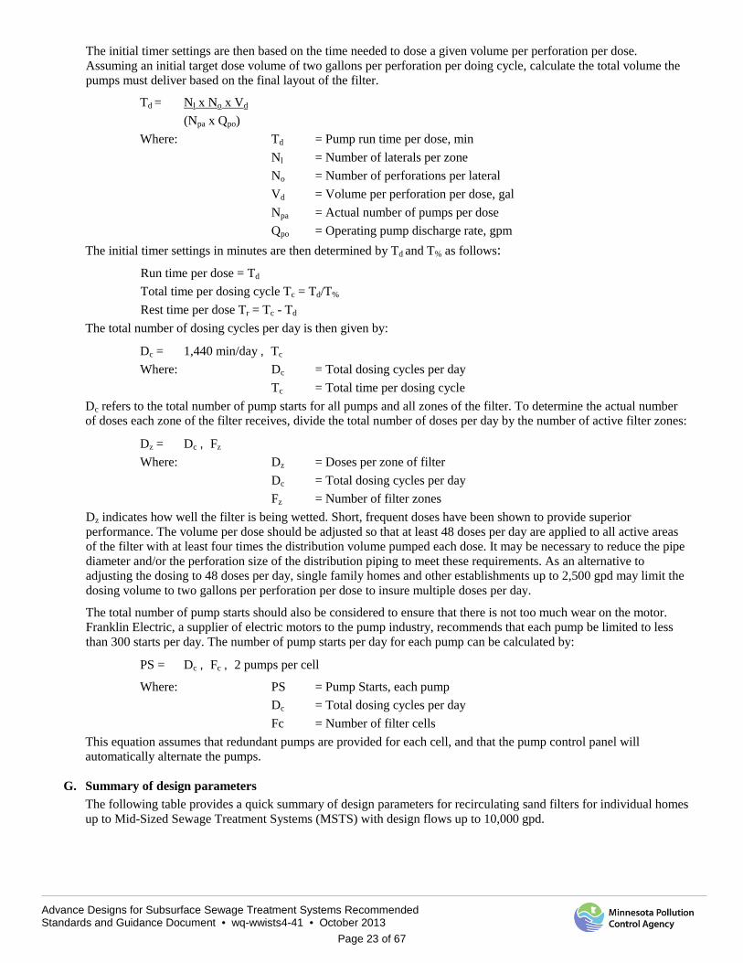
The initial timer settings are then based on the time needed to dose a given volume per perforation per dose. Assuming an initial target dose volume of two gallons per perforation per doing cycle, calculate the total volume the pumps must deliver based on the final layout of the filter.
Td = Nl x No x Vd (Npa x Qpo)
Where: Td = Pump run time per dose, min Nl = Number of laterals per zone No = Number of perforations per lateral Vd = Volume per perforation per dose, gal Npa = Actual number of pumps per dose Qpo = Operating pump discharge rate, gpm
The initial timer settings in minutes are then determined by Td and T% as follows: Run time per dose = Td Total time per dosing cycle Tc = Td/T% Rest time per dose Tr = Tc - Td
The total number of dosing cycles per day is then given by:
Dc = 1,440 min/day ¸ Tc Where: Dc = Total dosing cycles per day
Tc = Total time per dosing cycle Dc refers to the total number of pump starts for all pumps and all zones of the filter. To determine the actual number of doses each zone of the filter receives, divide the total number of doses per day by the number of active filter zones:
Dz = Dc ¸ Fz
Where: Dz = Doses per zone of filter Dc = Total dosing cycles per day Fz = Number of filter zones
Dz indicates how well the filter is being wetted. Short, frequent doses have been shown to provide superior performance. The volume per dose should be adjusted so that at least 48 doses per day are applied to all active areas of the filter with at least four times the distribution volume pumped each dose. It may be necessary to reduce the pipe diameter and/or the perforation size of the distribution piping to meet these requirements. As an alternative to adjusting the dosing to 48 doses per day, single family homes and other establishments up to 2,500 gpd may limit the dosing volume to two gallons per perforation per dose to insure multiple doses per day.
The total number of pump starts should also be considered to ensure that there is not too much wear on the motor. Franklin Electric, a supplier of electric motors to the pump industry, recommends that each pump be limited to less than 300 starts per day. The number of pump starts per day for each pump can be calculated by:
PS = Dc ¸ Fc ¸ 2 pumps per cell
Where: PS = Pump Starts, each pump Dc = Total dosing cycles per day
Fc = Number of filter cells This equation assumes that redundant pumps are provided for each cell, and that the pump control panel will automatically alternate the pumps.
G. Summary of design parameters
The following table provides a quick summary of design parameters for recirculating sand filters for individual homes up to Mid-Sized Sewage Treatment Systems (MSTS) with design flows up to 10,000 gpd.
Advance Designs for Subsurface Sewage Treatment Systems Recommended Standards and Guidance Document • wq-wwists4-41 • October 2013
Page 24 of 67
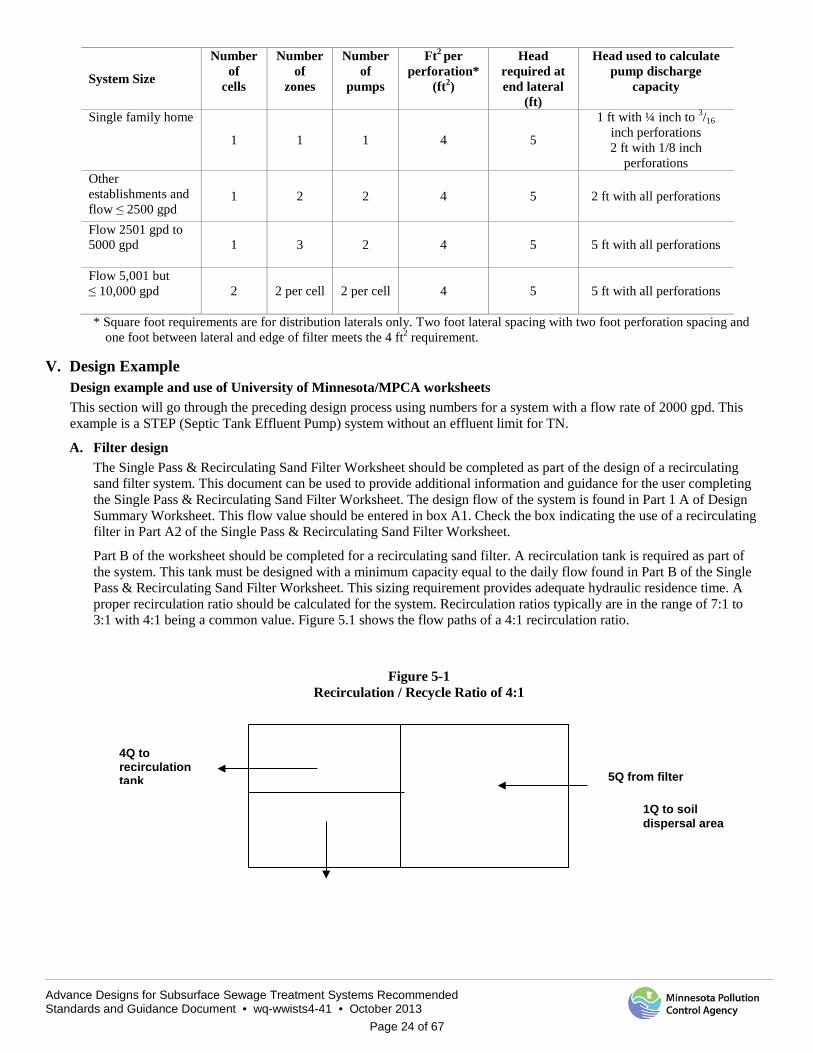
System Size
Number of
cells
Number of
zones
Number of
pumps
Ft2 per perforation*
(ft2)
Head required at end lateral
(ft)
Head used to calculate pump discharge
capacity
Single family home 1 1 1 4 5
1 ft with ¼ inch to 3/16 inch perforations 2 ft with 1/8 inch
perforations Other establishments and flow ≤ 2500 gpd
1 2 2 4 5 2 ft with all perforations
Flow 2501 gpd to 5000 gpd
1 3 2 4 5 5 ft with all perforations
Flow 5,001 but ≤ 10,000 gpd
2 2 per cell 2 per cell 4 5 5 ft with all perforations
* Square foot requirements are for distribution laterals only. Two foot lateral spacing with two foot perforation spacing and one foot between lateral and edge of filter meets the 4 ft2 requirement.
V. Design Example Design example and use of University of Minnesota/MPCA worksheets This section will go through the preceding design process using numbers for a system with a flow rate of 2000 gpd. This example is a STEP (Septic Tank Effluent Pump) system without an effluent limit for TN.
A. Filter design The Single Pass & Recirculating Sand Filter Worksheet should be completed as part of the design of a recirculating sand filter system. This document can be used to provide additional information and guidance for the user completing the Single Pass & Recirculating Sand Filter Worksheet. The design flow of the system is found in Part 1 A of Design Summary Worksheet. This flow value should be entered in box A1. Check the box indicating the use of a recirculating filter in Part A2 of the Single Pass & Recirculating Sand Filter Worksheet.
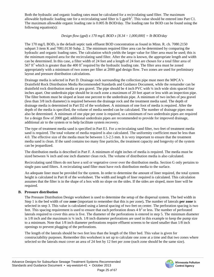
Part B of the worksheet should be completed for a recirculating sand filter. A recirculation tank is required as part of the system. This tank must be designed with a minimum capacity equal to the daily flow found in Part B of the Single Pass & Recirculating Sand Filter Worksheet. This sizing requirement provides adequate hydraulic residence time. A proper recirculation ratio should be calculated for the system. Recirculation ratios typically are in the range of 7:1 to 3:1 with 4:1 being a common value. Figure 5.1 shows the flow paths of a 4:1 recirculation ratio.
Figure 5-1 Recirculation / Recycle Ratio of 4:1
5Q from filter
4Q to recirculation tank
1Q to soil dispersal area
Advance Designs for Subsurface Sewage Treatment Systems Recommended Standards and Guidance Document • wq-wwists4-41 • October 2013
Page 25 of 67
Both the hydraulic and organic loading rates must be calculated for a recirculating sand filter. The maximum allowable hydraulic loading rate for a recirculating sand filter is 5 gpd/ft2. This value should be entered into Part C1. The maximum allowable organic loading rate is 0.005 lb BOD/day. The loading rate for BOD can be found using the following equation(s):
Design flow (gpd) x 170 mg/L BOD x [8.34 ÷ 1,000,000] = lb BOD/day
The 170 mg/L BOD5 is the default septic tank effluent BOD concentration as found in Minn. R. ch. 7080.2150 subpart 3 item K and 7081.0130 Subp. 2. The minimum required filter area can be determined by comparing the hydraulic and organic loading rates. The calculation which yields the larger value for filter area must be used; this is the minimum required area for the recirculating sand filter. After the area is known, the appropriate length and width can be determined. In this case, a filter width of 24 feet and a length of 24 feet are chosen for a total filter area of 567 ft2 which is greater than the 400 ft2 required by the hydraulic loading rate. The filter area must be zoned appropriately with a minimum of two zones per filter at 2000 gpd design flow. Two zones are used for preliminary layout and pressure distribution calculations.
Drainage media is selected in Part D. Drainage rock surrounding the collection pipe must meet the MPCA’s Drainfield Rock Distribution Media Recommended Standards and Guidance Document, while the remainder can be drainfield rock distribution media or pea gravel. The pipe should be 4 inch PVC with ¼ inch wide slots spaced four inches apart. One underdrain pipe should be in each zone a maximum of 20 feet apart or less with an inspection pipe. The filter bottom must be sloped at least one percent to the underdrain pipe. A minimum of two inches of pea gravel (less than 3/8 inch diameter) is required between the drainage rock and the treatment media sand. The depth of drainage media is determined in Part D2 of the worksheet. A minimum of one foot of media is required. After the depth of the media is specified, the volume of media needed can be calculated. The number of drainage pipes must also be determined. A minimum of one pipe per zone is required, so a minimum of two underdrain pipes are required for a design flow of 2000 gpd; additional underdrain pipes are recommended to provide for improved drainage, additional air to the system or to help facilitate system recovery.
The type of treatment media sand is specified in Part E1. For a recirculating sand filter, two feet of treatment media sand is required. The total volume of media required is also calculated. The uniformity coefficient must be less than 4.0. The effective size of the media must be between 1.5-2.5 mm. It is very important to ensure that the treatment media sand is clean. If the sand contains too many fine particles, the treatment capacity and longevity of the system can be jeopardized.
The distribution media is described in Part F. A minimum of eight inches of media is required. The media must be sized between ¾ inch and one inch diameter clean rock. The volume of distribution media is also calculated.
Recirculating sand filters do not have a soil or vegetative cover over the distribution media. Section G only pertains to single pass sand filters. A recirculating sand filter must have rock distribution media to the surface. An adequate liner must be provided for the system. In order to determine the amount of liner required, the total system height is calculated in Part H of the worksheet. The width and length of liner required is calculated. This calculation assumes that the filter is in the shape of a box with no slope on the sides. If the sides are sloped, more liner will be required.
B. Pressure distribution The Pressure Distribution Design worksheet is used to determine the setup of the dispersal system. The bed width in Step 1 is the bed width of one zone (important to remember that this is per zone). The number of laterals per zone is selected in step 3. This value is calculated using a lateral spacing of two feet on center. The perforation spacing is two feet. This spacing requirement is used to ensure that each perforation doses 4 ft2 or less. The number of perforated laterals required to cover this area is five. The diameter of the perforations is entered in step 5. The minimum diameter is 1/8 inch and the maximum is ¼ inch. 1/8 inch diameter perforations are used in this example to keep the pump size to a minimum. Note that 1/8 inch diameter perforations require effluent screens to be sized smaller than 1/8 inch openings to prevent plugging of the perforations.
The length of the laterals should be two feet less than the length of the filter bed. This value is given for constructability purposes. Remember this worksheet is set up to calculate one zone at a time and that two zones where selected so the laterals must cover an area of 24 feet by 12 feet per zone (each zone should be the same size).

Advance Designs for Subsurface Sewage Treatment Systems Recommended Standards and Guidance Document • wq-wwists4-41 • October 2013
Page 26 of 67
The number of perforations per lateral is found in steps 7 and 8. This value should be compared with the appropriate value found in Table 1. Use Table 1 along with the perforation diameter, pipe diameter and perforation spacing to find the maximum number of perforations per lateral to ensure less than ten percent discharge variation. The value in step 8 should be less than or equal to the value found in Table 1. The pipe diameter used in this example is 1.25 inches to ensure that 48 doses per day are possible.
Step 12 calculates the bed area per zone and finds the discharge coverage per perforation. This value should be less than or equal to 4 ft2/perforation, but may be a bit larger due to the sides and ends of the bed. The minimum average head in step 13 is five feet for this system. This value is found under Table 3. The perforation discharge is found based on Table 3 with the appropriate head and perforation diameter.
The flow rate found in step 15 is used as the required flow for the Pump Selection Design worksheet. The distribution manifold can be set up with either an end or center connection. The manifold pipe diameter should be greater than the lateral pipe diameter.
C. Pump Size The Pump Design Selection worksheet is used to determine the required flow rate and associated head loss for the distribution system. Pressure distribution must be used for recirculating media filters. Part 2 of this worksheet calculates the required head pressure for the system. The elevation difference is the distance between the pump inlet and the highest point of the distribution pipe; this is greatest possible elevation difference that can be created by the system. This value is the static head.
The head loss due to the distribution manifold is entered into Part 2B. For pressure distribution, enter a value of ten feet. This number is used to ensure that there is at least five feet of head at the end of the distribution system as required by Minn. R. 7080.2100 subpart 4, item C. Any additional head loss due to special equipment, etc. can also be accounted for in this section.
The distribution pipe diameter is entered in step 2D. The minimum pipe diameter is 1.5 inches and the maximum is three inches. The head loss due to friction is calculated in step 2E using Table 1. Table 1 calculates this loss using the Hazen Williams equation with a C value of 130 based on the use of PVC pipe and is shown for each 100 feet of PVC pipe.
The equivalent pipe length is used to account for losses in the system due to various fittings. A 25 percent increase in effective length has been found to be a good estimate of the friction losses rather than counting the individual pipe fitting throughout the system. Larger systems with many fittings may require the head losses due to the fittings to be determined. The total head required for the pump is determined at the end of the worksheet.
A pump must be selected that delivers the correct flow rate given in step 1, along with the required total head from step 2H. Due to reliability requirements, a minimum of two pumps is required. Pumps operate at many different points called a pump curve. This pump curve is found by plotting various flow rate versus required head. A pump will operate anywhere along the pump curve, but can only deliver a certain flow rate to match the corresponding head requirement. The selected pumps should be capable of providing a recirculation ratio between 3:1 and 7:1.
D. Pump tank sizing/dosing worksheet The pump tank is typically sized large enough to accommodate timed dosed of effluent with at least one day of storage volume. The tank should be equipped with high and low level floats to override the timed dosing and protect the pumps. The control system should provide an auto dialer to alert the service provider of pump failure and to turn the second pump on when the high level float is actuated. Tanks prior to sand filter must have an effluent screen to help minimize the plugging of perforations. Screen size should be less than the perforation size to prevent plugging.
The ideal dosing volume and frequency provides a thin layer of flow over the sand filter media while providing good oxygen transfer between dose events. To enhance treatment, a minimum of 48 doses per day is required, with each dose volume having at least four times the distribution pipe volume. The dosing system in this design example must include an alternating two pump system for each zone.
For this example, tanks must have a 2000 gallon operating capacity between the inlet pipes to the pump off float. The dosing volume calculated in this worksheet will be calculated for one zone so that the pumping volume will correlate with one pumping event. Step 5 determines the minimum pump out volume which is four times the distribution pipe volume and can be taken from line 17 of the pressure distribution worksheet since that was also calculated for one zone.

Advance Designs for Subsurface Sewage Treatment Systems Recommended Standards and Guidance Document • wq-wwists4-41 • October 2013
Page 27 of 67
Step 6 on page 36 provides the maximum pump out volume as required in Minn. R. ch. 7080.2100 subp 4 D. This volume should be based on the design flow for one zone or 1,000 gpd in this example. To do this on the automated worksheet, you need to go to the Design Summary page and reset the flow to the design flow divided by the number of zones (2000 gpd/2 zones).
Step 7 is used to find the design dosing volume which will produce 48 doses or more per day. The dosing volume must be between the minimum 20 gallons and the maximum 250 gallons found in steps 5 and 6. The design flow used in this step is the flow that will be pumped to one zone in one day using a 4:1 recirculation rate, or 5,000 gpd. The flow value in the Design Summary tab will have to be changed to 5,000 gpd. Picking a dosing volume of 104 gallons, which is between the minimum and maximum values, will provide 48 doses per day; this is the minimum required doses per day. The 48 doses per day is a design parameter intended to create small dose volumes. In practice, the actual flow will be lower than the design flow resulting in fewer doses per day. The system must still be designed for 48 doses or more per day and operated as near to 48 doses per day as possible. Setting the timer on this system will result in a run time of 4.4 minutes (called the on time) and an off time of 25.6 minutes for each zone. This value must be adjusted in the field as the actual pumping rate will vary from the design pumping rate of 25 gpm.
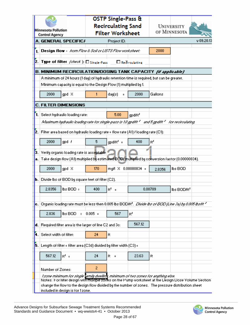
Advance Designs for Subsurface Sewage Treatment Systems Recommended Standards and Guidance Document • wq-wwists4-41 • October 2013
Page 28 of 67
x
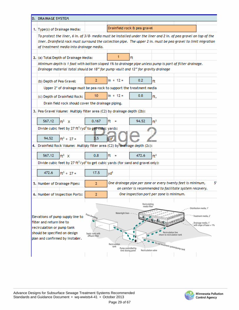
Advance Designs for Subsurface Sewage Treatment Systems Recommended Standards and Guidance Document • wq-wwists4-41 • October 2013
Page 29 of 67
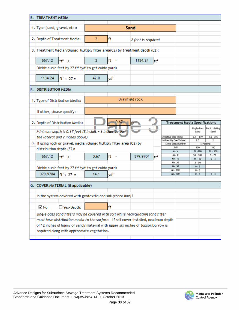
Advance Designs for Subsurface Sewage Treatment Systems Recommended Standards and Guidance Document • wq-wwists4-41 • October 2013
Page 30 of 67
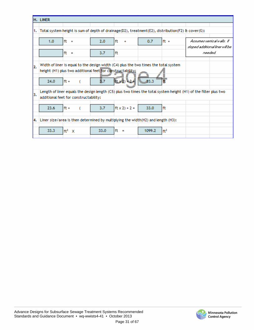
Advance Designs for Subsurface Sewage Treatment Systems Recommended Standards and Guidance Document • wq-wwists4-41 • October 2013
Page 31 of 67
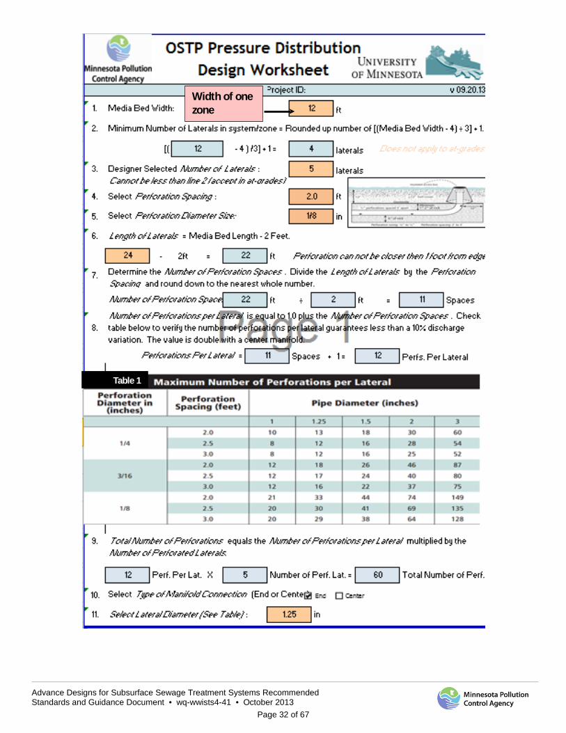
Advance Designs for Subsurface Sewage Treatment Systems Recommended Standards and Guidance Document • wq-wwists4-41 • October 2013
Page 32 of 67
Width of one zone
Table 1
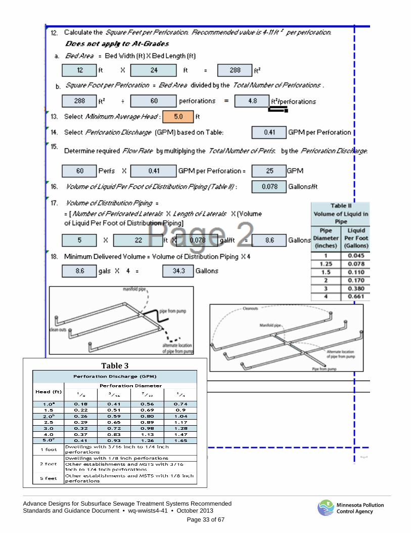
Advance Designs for Subsurface Sewage Treatment Systems Recommended Standards and Guidance Document • wq-wwists4-41 • October 2013
Page 33 of 67
Table 3
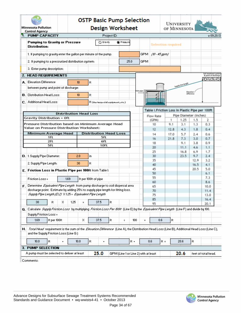
Advance Designs for Subsurface Sewage Treatment Systems Recommended Standards and Guidance Document • wq-wwists4-41 • October 2013
Page 34 of 67
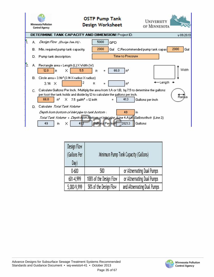
Advance Designs for Subsurface Sewage Treatment Systems Recommended Standards and Guidance Document • wq-wwists4-41 • October 2013
Page 35 of 67
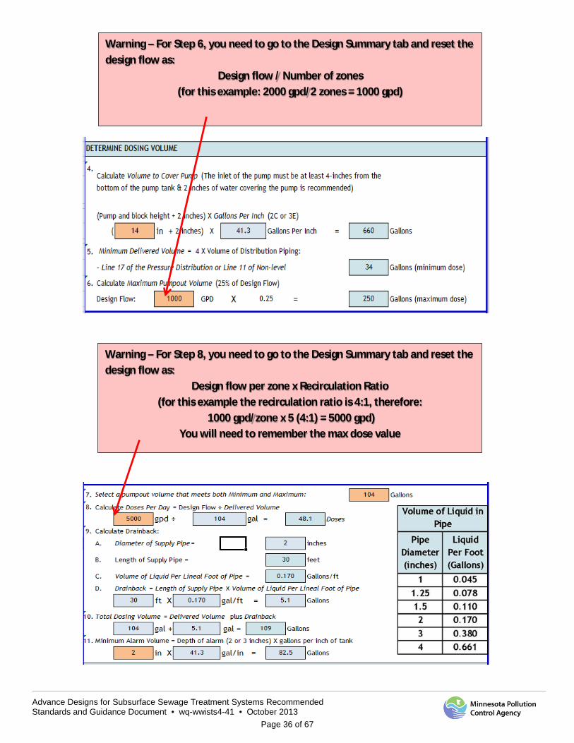
Advance Designs for Subsurface Sewage Treatment Systems Recommended Standards and Guidance Document • wq-wwists4-41 • October 2013
Page 36 of 67
Warning – For Step 6, you need to go to the Design Summary tab and reset the design flow as:
Design flow / Number of zones (for this example: 2000 gpd/2 zones = 1000 gpd)
Warning – For Step 8, you need to go to the Design Summary tab and reset the design flow as:
Design flow per zone x Recirculation Ratio (for this example the recirculation ratio is 4:1, therefore:
1000 gpd/zone x 5 (4:1) = 5000 gpd) You will need to remember the max dose value
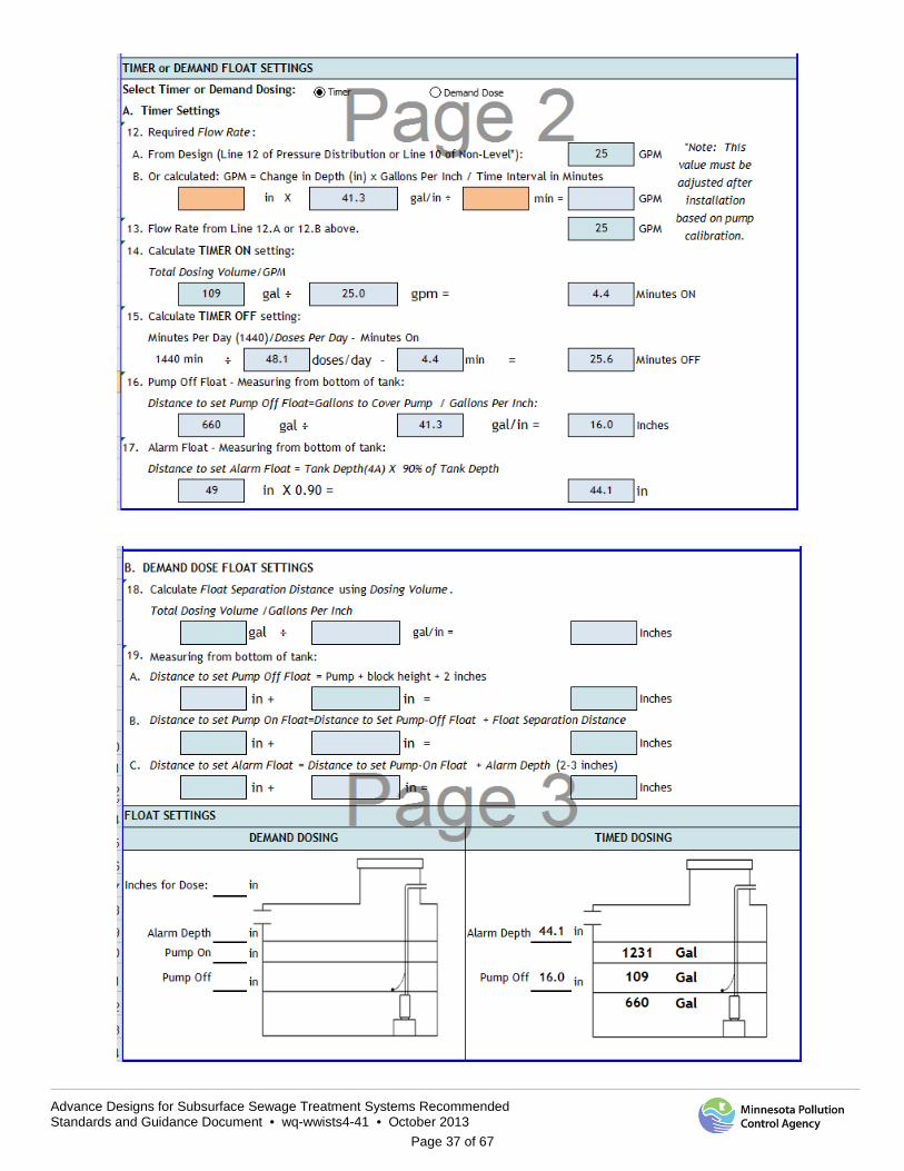
Advance Designs for Subsurface Sewage Treatment Systems Recommended Standards and Guidance Document • wq-wwists4-41 • October 2013
Page 37 of 67
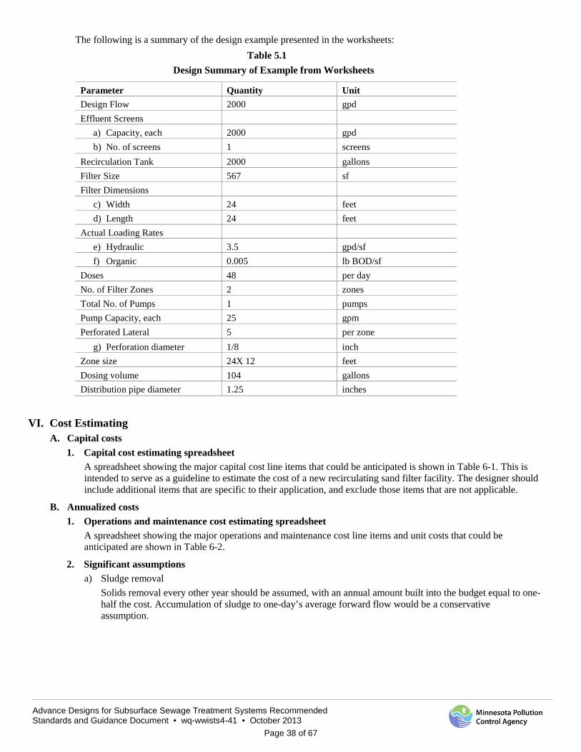
Advance Designs for Subsurface Sewage Treatment Systems Recommended Standards and Guidance Document • wq-wwists4-41 • October 2013
Page 38 of 67
The following is a summary of the design example presented in the worksheets: Table 5.1
Design Summary of Example from Worksheets
VI. Cost Estimating A. Capital costs
1. Capital cost estimating spreadsheet A spreadsheet showing the major capital cost line items that could be anticipated is shown in Table 6-1. This is intended to serve as a guideline to estimate the cost of a new recirculating sand filter facility. The designer should include additional items that are specific to their application, and exclude those items that are not applicable.
B. Annualized costs 1. Operations and maintenance cost estimating spreadsheet
A spreadsheet showing the major operations and maintenance cost line items and unit costs that could be anticipated are shown in Table 6-2.
2. Significant assumptions a) Sludge removal
Solids removal every other year should be assumed, with an annual amount built into the budget equal to one-half the cost. Accumulation of sludge to one-day’s average forward flow would be a conservative assumption.
Parameter Quantity Unit Design Flow 2000 gpd Effluent Screens
a) Capacity, each 2000 gpd b) No. of screens 1 screens
Recirculation Tank 2000 gallons Filter Size 567 sf Filter Dimensions
c) Width 24 feet d) Length 24 feet
Actual Loading Rates e) Hydraulic 3.5 gpd/sf f) Organic 0.005 lb BOD/sf
Doses 48 per day No. of Filter Zones 2 zones Total No. of Pumps 1 pumps Pump Capacity, each 25 gpm Perforated Lateral 5 per zone
g) Perforation diameter 1/8 inch Zone size 24X 12 feet Dosing volume 104 gallons Distribution pipe diameter 1.25 inches

Advance Designs for Subsurface Sewage Treatment Systems Recommended Standards and Guidance Document • wq-wwists4-41 • October 2013
Page 39 of 67
Table 6-1 Recirculating Sand Filter Capital Cost Estimating Sheet
Item Quantity Units Unit Cost Total Cost Land acres Site work cy Site electrical (3 Phase) Flow meters each Samplers each Septic tanks each Recirculation tank each Splitter/Valve vault each RSF system
· Earthwork cy · Filter liner sy · Underdrain piping lf · Coarse filter media cy · Fine filter media cy · Distribution piping & valves lot
Pumps and Controls lot Control building (incl. elec and HVAC) sf Fencing lf Yard piping lf Electrical (10%) Contractor OH&P (20%) Subtotal Capital Contingencies (25%) Subtotal Engineering (20%) Legal and Administrative (5%) Total estimated capital cost
Table 6-2
Recirculating Sand Filter O&M Cost Estimating
Operation and Maintenance Costs Quantity Units Unit Cost Annual Cost Labor hours/yr Electric power kWh Supplies lot Maintenance and Repair Laboratory testing Sludge disposal gallons Annual O&M cost
Advance Designs for Subsurface Sewage Treatment Systems Recommended Standards and Guidance Document • wq-wwists4-41 • October 2013
Page 40 of 67
b) Power Power costs will vary across the state. A current estimate of the cost per kilowatt-hour should be used to estimate annual power costs for the dosing pumps. Power cost for the dosing pumps can be done by multiplying the total number of pumps times the average running time, and converting horsepower into kilowatts as per the following formula:
Annual Power Cost = (Np)(T% )(24 hours)(HP)(0.75)($/kW-hr)(365)
Where: Np = Number of pumps T% = Percent daily run time
HP = Horsepower of each pump
c) Maintenance An annual set-aside for equipment replacement should be built into the budget. The amount set aside should be based on the original cost of the equipment, and prorated out over the expected design life of the equipment. The annual cost should also account for site maintenance such as grass mowing and snow removal.
d) Labor The estimated cost for labor should be based on the total compensation for the operating staff, including any benefits, plus any administrative salaries for meetings, billing, etc. The estimated hours needed should consider the monitoring and sampling requirements of the particular facility, and include provisions for travel, periodic maintenance such as vegetation removal, flushing of laterals and regular pump maintenance.
e) Sampling and analysis The cost for a facility’s sampling and analysis program will vary from one facility to another based on the permit. The cost should be based on the total number of samples expected in a year, and include the cost of analysis by a certified laboratory, plus the costs of sample delivery.
VII. Operation and Maintenance A. Operational concerns
1. Filter saturation and ponding The organism population within a recirculating sand filter multiplies in proportion to the organic loading rate. When food is not coming in, the process of endogenous respiration takes over in which organisms consume each other, a sort of “survival of the fittest” phenomenon. This process keeps the filter from building a large organic content of biological cells. If the system is too heavily loaded, biological cells and biodegradation byproducts accumulate, and the pores of the sand system may become filled with organic matter. This then begins to slow the flow through the sand filter and eventually can lead to a filter with ponding on the surface. Therefore, it is necessary to balance the loading rate with the rate at which the organisms can decompose the applied material and keep the development of a large bacterial cell mass from accumulating.
It is expected that some degree of biomass buildup will occur directly below the distribution headers. This causes the wastewater to spread some laterally in the filter to media that is not directly below the headers. The buildup of biomass below the distribution media should not be so great as to cause wastewater to appear on the surface of the filter. Ponding that is visible at the surface is evidence of excessive biomass fouling, and the service provider should begin an immediate investigation. At a minimum, the filter cell should be taken off line. The distribution laterals should be exposed in numerous places to determine if: 1) all areas of the sand filter are being wetted, 2) fouling is localized to a small area or 3) fouling is occurring throughout the sand filter.
When some areas of the sand filter are ponded, while other areas are dry, the distribution laterals are likely clogged; the lines should be flushed or jetted. Additional information about distribution pipe maintenance is provided in Section B.6. (maintenance issues for distribution piping) contained in this section of the document.
If the entire sand filter appears to be fouled, then portions of the filter should be taken off line and allowed to rest. Without food, endogenous respiration will occur, and some of the fouling will be reduced. The source of the fouling should be investigated by determining the organic loading rate to check if the filter was being overloaded. If the recirculation has been eliminated, or if it has been very low, the dissolved oxygen content of the water being applied to the filter may have been too low.
Advance Designs for Subsurface Sewage Treatment Systems Recommended Standards and Guidance Document • wq-wwists4-41 • October 2013
Page 41 of 67
2. Freezing Water that is kept moving is less likely to freeze. In a coarse sand filter (D10 >1.5 mm), wastewater will percolate through the media fast enough to prevent freezing, even in Minnesota.
Freezing is a concern with fine or clogged media. In subfreezing ambient temperatures, ponded wastewater may cool to the point where freezing occurs. Once a filter surface freezes, it effectively prevents its use for treatment until it thaws. Allowing an entire bed to freeze would leave a homeowner or community without any secondary treatment.
One of the keys to preventing a frozen filter is to transfer flow onto a rested filter cell in the early fall while the temperature is still warm enough to establish bacteria. Frequent, smaller doses to minimize ponding will also help to avoid freezing.
3. Pumps and electrical Pumps are generally controlled by timers, floats or some type of electronic level sensor. Pumping systems should be provided with a redundant pump to provide reliability. The dosing pumps must be able to meet the worst-case instantaneous flow rate requirement with one unit out of service. One of the following must be provided to prevent hydraulic overloading in the event of a power outage: 1) backup generator installed on site, 2) provisions to connect to a portable generator or 3) at least a location for a licensed maintainer to pump out the tanks in emergencies.
4. Odors a) Primary treatment units
Odors can originate in the septic tank, but are generally not detectable away from the tank. Adequate venting through the building vent pipes is typically effective; in special circumstances, carbon filters may be required in vent stacks to further reduce odors.
b) Media bed Odors in the sand filter media are uncommon and are an indicator that something is wrong. As an aerobic system, the products of metabolism are chiefly carbon dioxide and water, which are odorless. Odors are produced under anaerobic conditions and are an indication that: 1) dissolved oxygen in the filter is being depleted and 2) that BOD and ammonia removal is likely being impacted.
B. Maintenance issues 1. Time required by a service provider
A recirculating sand filter is typically operated and maintained by a single service provider, although a backup should be trained for when the primary service provider is unavailable. A management plan for recirculating sand filters is contained in Appendix C. An operating permit template is shown in Appendix D.
Depending on the frequency of visits and sampling requirements, the average amount of time spent monitoring a recirculating sand filter facility ranges from about two to seven hours per week. For larger facilities, daily visits might be needed while for single family homes, annual inspections are typically required. On non-sampling days, service providers report that the daily checkup should take about 15 minutes. On sampling days, one hour is typically needed to collect samples and prepare them for delivery to the lab. Additional time is required for periodic maintenance of equipment, and for maintenance of the sand filter itself, including an item like lateral cleaning.
For small facilities equipped with an alarm dialer, daily visits may not be necessary.
2. Sampling The approving local unit of government will define monitoring requirements in the facility’s operating permit. Such monitoring can provide a benchmark level of performance for a system, allowing the service provider to observe trends in performance and address a potential issue before it is allowed to progress to failure of the system. The operating permit should identify a minimum recommended sampling protocol for recirculating sand filter systems that will provide the service provider with sufficient information on the performance of the system.
An example of monitoring requirements that are specified in local operating permits for different flows might be as follows: a) Systems serving up to four homes (< 1500 gpd)
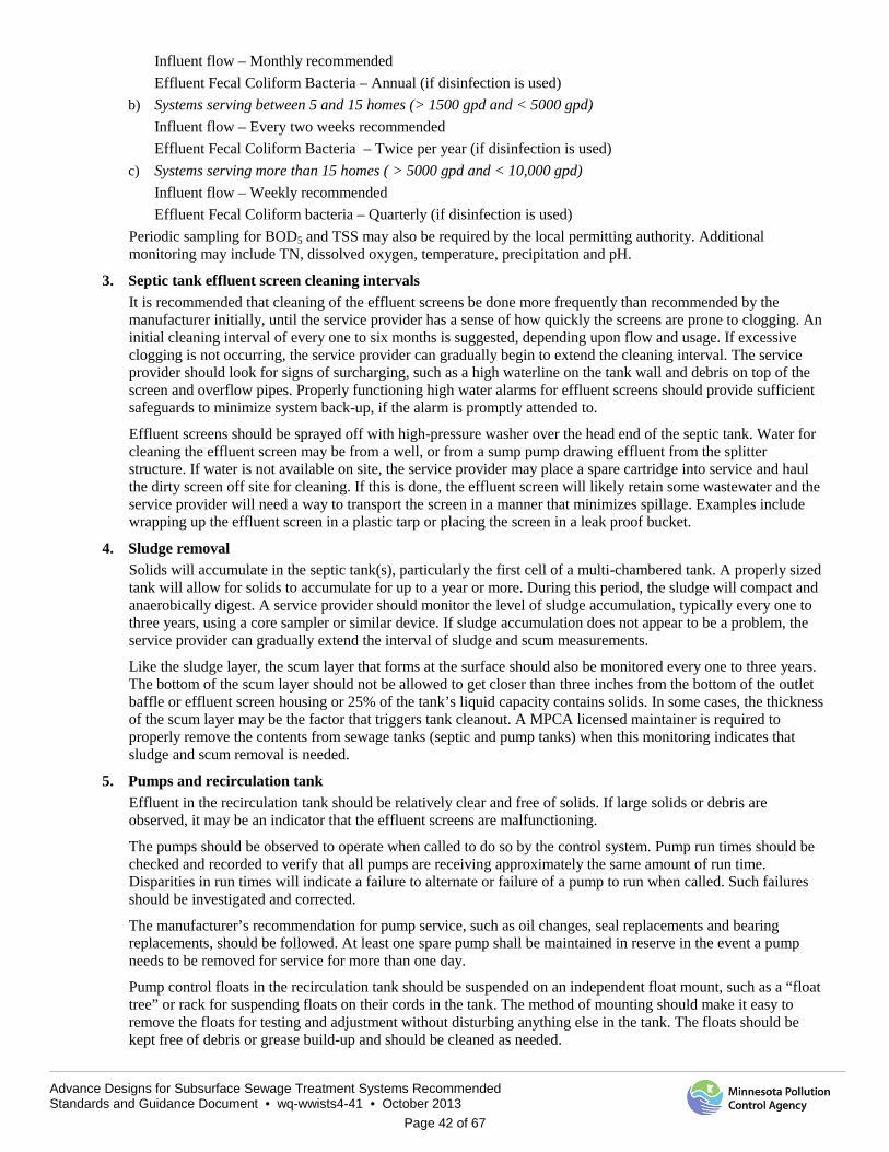
Advance Designs for Subsurface Sewage Treatment Systems Recommended Standards and Guidance Document • wq-wwists4-41 • October 2013
Page 42 of 67
Influent flow – Monthly recommended Effluent Fecal Coliform Bacteria – Annual (if disinfection is used)
b) Systems serving between 5 and 15 homes (> 1500 gpd and < 5000 gpd) Influent flow – Every two weeks recommended Effluent Fecal Coliform Bacteria – Twice per year (if disinfection is used)
c) Systems serving more than 15 homes ( > 5000 gpd and < 10,000 gpd) Influent flow – Weekly recommended Effluent Fecal Coliform bacteria – Quarterly (if disinfection is used)
Periodic sampling for BOD5 and TSS may also be required by the local permitting authority. Additional monitoring may include TN, dissolved oxygen, temperature, precipitation and pH.
3. Septic tank effluent screen cleaning intervals It is recommended that cleaning of the effluent screens be done more frequently than recommended by the manufacturer initially, until the service provider has a sense of how quickly the screens are prone to clogging. An initial cleaning interval of every one to six months is suggested, depending upon flow and usage. If excessive clogging is not occurring, the service provider can gradually begin to extend the cleaning interval. The service provider should look for signs of surcharging, such as a high waterline on the tank wall and debris on top of the screen and overflow pipes. Properly functioning high water alarms for effluent screens should provide sufficient safeguards to minimize system back-up, if the alarm is promptly attended to.
Effluent screens should be sprayed off with high-pressure washer over the head end of the septic tank. Water for cleaning the effluent screen may be from a well, or from a sump pump drawing effluent from the splitter structure. If water is not available on site, the service provider may place a spare cartridge into service and haul the dirty screen off site for cleaning. If this is done, the effluent screen will likely retain some wastewater and the service provider will need a way to transport the screen in a manner that minimizes spillage. Examples include wrapping up the effluent screen in a plastic tarp or placing the screen in a leak proof bucket.
4. Sludge removal Solids will accumulate in the septic tank(s), particularly the first cell of a multi-chambered tank. A properly sized tank will allow for solids to accumulate for up to a year or more. During this period, the sludge will compact and anaerobically digest. A service provider should monitor the level of sludge accumulation, typically every one to three years, using a core sampler or similar device. If sludge accumulation does not appear to be a problem, the service provider can gradually extend the interval of sludge and scum measurements. Like the sludge layer, the scum layer that forms at the surface should also be monitored every one to three years. The bottom of the scum layer should not be allowed to get closer than three inches from the bottom of the outlet baffle or effluent screen housing or 25% of the tank’s liquid capacity contains solids. In some cases, the thickness of the scum layer may be the factor that triggers tank cleanout. A MPCA licensed maintainer is required to properly remove the contents from sewage tanks (septic and pump tanks) when this monitoring indicates that sludge and scum removal is needed.
5. Pumps and recirculation tank Effluent in the recirculation tank should be relatively clear and free of solids. If large solids or debris are observed, it may be an indicator that the effluent screens are malfunctioning.
The pumps should be observed to operate when called to do so by the control system. Pump run times should be checked and recorded to verify that all pumps are receiving approximately the same amount of run time. Disparities in run times will indicate a failure to alternate or failure of a pump to run when called. Such failures should be investigated and corrected.
The manufacturer’s recommendation for pump service, such as oil changes, seal replacements and bearing replacements, should be followed. At least one spare pump shall be maintained in reserve in the event a pump needs to be removed for service for more than one day.
Pump control floats in the recirculation tank should be suspended on an independent float mount, such as a “float tree” or rack for suspending floats on their cords in the tank. The method of mounting should make it easy to remove the floats for testing and adjustment without disturbing anything else in the tank. The floats should be kept free of debris or grease build-up and should be cleaned as needed.
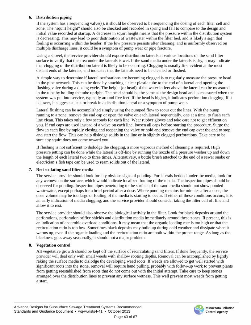
Advance Designs for Subsurface Sewage Treatment Systems Recommended Standards and Guidance Document • wq-wwists4-41 • October 2013
Page 43 of 67
6. Distribution piping If the system has a sequencing valve(s), it should be observed to be sequencing the dosing of each filter cell and zone. The “squirt height” should also be checked and recorded in spring and fall to compare to the design and initial value recorded at startup. A decrease in squirt height means that the pressure within the distribution system is decreasing. This may lead to poor distribution of wastewater within the filter bed, and is likely a sign that fouling is occurring within the header. If the low pressure persists after cleaning, and is uniformly observed on multiple discharge lines, it could be a symptom of pump wear or pipe fracture.
Using a shovel, the service provider should expose distribution laterals at various locations on the sand filter surface to verify that the area under the laterals is wet. If the sand media under the laterals is dry, it may indicate that clogging of the distribution lateral is likely to be occurring. Clogging is usually first evident at the most distant ends of the laterals, and indicates that the laterals need to be cleaned or flushed.
A simple way to determine if lateral perforations are becoming clogged is to regularly measure the pressure head in the pipe network. This can be done by attaching a clear plastic tube to the end of a lateral and opening the flushing valve during a dosing cycle. The height (or head) of the water in feet above the lateral can be measured in the tube by holding the tube upright. The head should be the same as the design head and as measured when the system was put into service, typically around five feet. If the head is higher, it indicates perforation clogging. If it is lower, it suggests a leak or break in a distribution lateral or a symptom of pump wear.
Lateral flushing can be accomplished simply using the pumped flow to scour out the lines. With the pump running to a zone, remove the end cap or open the valve on each lateral sequentially, one at a time, to flush each line clean. This takes only a few seconds for each line. Wear rubber gloves and take care not to get effluent on you. If end caps are used instead of a valve on each line, loosen all caps before starting the procedure. Surge the flow in each line by rapidly closing and reopening the valve or hold and remove the end cap over the end to stop and start the flow. This can help dislodge solids in the line or in slightly clogged perforations. Take care to be sure any squirt does not come toward you.
If flushing is not sufficient to dislodge the clogging, a more vigorous method of cleaning is required. High pressure jetting can be done while the lateral is off-line by running the nozzle of a pressure washer up and down the length of each lateral two to three times. Alternatively, a bottle brush attached to the end of a sewer snake or electrician’s fish tape can be used to ream solids out of the lateral.
7. Recirculating sand filter media The service provider should look for any obvious signs of ponding. For laterals bedded under the media, look for any wetness on the surface, which would indicate localized fouling of the media. The inspection pipes should be observed for ponding. Inspection pipes penetrating to the surface of the sand media should not show ponded wastewater, except perhaps for a brief period after a dose. Where ponding remains for minutes after a dose, the dose volume may be too large or fouling of the media is starting to occur. If either of these conditions occurs, it is an early indication of media clogging, and the service provider should consider taking the filter cell off line and allow it to rest.
The service provider should also observe the biological activity in the filter. Look for black deposits around the perforations, perforation orifice shields and distribution media immediately around these zones. If present, this is an indication of anaerobic overload conditions. It may mean that the organic loading rate is too high or that the recirculation ratio is too low. Sometimes black deposits may build up during cold weather and dissipate when it warms up, even if the organic loading and the recirculation ratio are both within the proper range. As long as the blackness goes away seasonally, it should not a major problem.
8. Vegetation control All vegetative growth should be kept off the surface of recirculating sand filters. If done frequently, the service provider will deal only with small weeds with shallow rooting depths. Removal can be accomplished by lightly raking the surface media to dislodge the developing weed roots. If weeds are allowed to get well started with significant roots into the stone, removal will require hand pulling, probably with follow-up work to prevent plants from getting reestablished from roots that do not come out with the initial attempt. Take care to keep stones arranged over the distribution lines to prevent any surface wetness. This well prevent most weeds from getting a start.
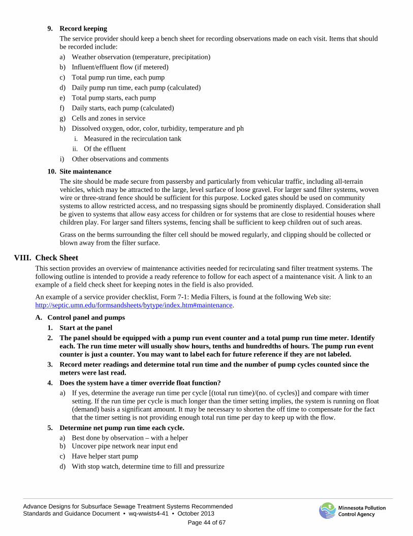
Advance Designs for Subsurface Sewage Treatment Systems Recommended Standards and Guidance Document • wq-wwists4-41 • October 2013
Page 44 of 67
9. Record keeping The service provider should keep a bench sheet for recording observations made on each visit. Items that should be recorded include: a) Weather observation (temperature, precipitation) b) Influent/effluent flow (if metered) c) Total pump run time, each pump d) Daily pump run time, each pump (calculated) e) Total pump starts, each pump f) Daily starts, each pump (calculated) g) Cells and zones in service h) Dissolved oxygen, odor, color, turbidity, temperature and ph
i. Measured in the recirculation tank ii. Of the effluent
i) Other observations and comments
10. Site maintenance The site should be made secure from passersby and particularly from vehicular traffic, including all-terrain vehicles, which may be attracted to the large, level surface of loose gravel. For larger sand filter systems, woven wire or three-strand fence should be sufficient for this purpose. Locked gates should be used on community systems to allow restricted access, and no trespassing signs should be prominently displayed. Consideration shall be given to systems that allow easy access for children or for systems that are close to residential houses where children play. For larger sand filters systems, fencing shall be sufficient to keep children out of such areas.
Grass on the berms surrounding the filter cell should be mowed regularly, and clipping should be collected or blown away from the filter surface.
VIII. Check Sheet This section provides an overview of maintenance activities needed for recirculating sand filter treatment systems. The following outline is intended to provide a ready reference to follow for each aspect of a maintenance visit. A link to an example of a field check sheet for keeping notes in the field is also provided.
An example of a service provider checklist, Form 7-1: Media Filters, is found at the following Web site: http://septic.umn.edu/formsandsheets/bytype/index.htm#maintenance.
A. Control panel and pumps 1. Start at the panel 2. The panel should be equipped with a pump run event counter and a total pump run time meter. Identify
each. The run time meter will usually show hours, tenths and hundredths of hours. The pump run event counter is just a counter. You may want to label each for future reference if they are not labeled.
3. Record meter readings and determine total run time and the number of pump cycles counted since the meters were last read.
4. Does the system have a timer override float function? a) If yes, determine the average run time per cycle [(total run time)/(no. of cycles)] and compare with timer
setting. If the run time per cycle is much longer than the timer setting implies, the system is running on float (demand) basis a significant amount. It may be necessary to shorten the off time to compensate for the fact that the timer setting is not providing enough total run time per day to keep up with the flow.
5. Determine net pump run time each cycle. a) Best done by observation – with a helper b) Uncover pipe network near input end c) Have helper start pump d) With stop watch, determine time to fill and pressurize
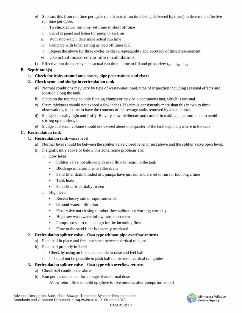
Advance Designs for Subsurface Sewage Treatment Systems Recommended Standards and Guidance Document • wq-wwists4-41 • October 2013
Page 45 of 67
e) Subtract this from run time per cycle (check actual run time being delivered by timer) to determine effective run time per cycle. i. To check actual run time, set timer to short off time
ii. Stand at panel and listen for pump to kick on iii. With stop watch, determine actual run time iv. Compare with timer setting as read off timer dial v. Repeat the above for three cycles to check repeatability and accuracy of time measurement
vi. Use actual measured run time in calculations f) Effective run time per cycle is actual run time – time to fill and pressurize: teff = tact - tfill
B. Septic tank(s) 1. Check for leaks around tank seams, pipe penetrations and risers 2. Check scum and sludge in recirculation tank
a) Normal conditions may vary by type of wastewater input, time of inspection including seasonal effects and location along the tank.
b) Scum on the top may be only floating clumps or may be a continuous mat, which is unusual. c) Scum thickness should not exceed a few inches. If scum is consistently more than this in two to three
observations, it is time to have the contents of the sewage tanks removed by a maintainer. d) Sludge is usually light and fluffy. Be very slow, deliberate and careful in making a measurement to avoid
stirring up the sludge. e) Sludge and scum volume should not exceed about one-quarter of the tank depth anywhere in the tank.
C. Recirculation tank 1. Recirculation tank water level
a) Normal level should be between the splitter valve closed level or just above and the splitter valve open level. b) If significantly above or below this zone, some problems are:
i. Low level · Splitter valve not allowing desired flow to return to the tank · Blockage in return line or filter drain · Sand filter drain blinded off, pumps have just run and are set to run for too long a time · Tank leaks · Sand filter is partially frozen
ii. High level · Recent heavy rain or rapid snowmelt · Ground water infiltration · Float valve not closing or other flow splitter not working correctly · High raw wastewater inflow rate, short term · Pumps not set to run enough for the incoming flow · Flow to the sand filter is severely restricted
2. Recirculation splitter valve – float type without pipe overflow returns a) Float ball in place and free, not stuck between vertical rails, etc b) Float ball properly inflated
i. Check by using an L-shaped paddle to raise and feel ball ii. It should not be possible to push ball out between vertical rail guides
3. Recirculation splitter valve – float type with overflow returns a) Check ball condition as above b) Run pumps on manual for a longer than normal dose
i. Allow return flow to build up (three to five minutes after pumps turned on)
Advance Designs for Subsurface Sewage Treatment Systems Recommended Standards and Guidance Document • wq-wwists4-41 • October 2013
Page 46 of 67
ii. Check to be sure all return lines are flowing after return flow has built up ii. Float valve should close
iii. Check flow rate into final dose tank to be sure float by-pass is working correctly 4. Recirculation tank contents (i.e. blend of wastewater and return water)
a) pH throughout the tank should be near neutral (pH of 7). b) Dissolved oxygen content of the tank will vary. It should be higher, 4 to 5 mg/L or more, near to where the
filtered water is returning from the sand filter. The incoming sewage should have dissolved oxygen of less than 1 mg/L. The blended mix in the tank, pumped to the sand filter, should be less than 2 mg/L.
c) Temperature in the tank in close proximity to the pumps dosing the recirculating sand filter should be greater than 40°F.
d) Odor of the tank should be a faint septic smell near the incoming end of the tank to a musty odor near the filtered water return end of the tank.
D. Surface observations of the recirculating sand filter bed 1. Weed growth
a) All growth should be kept off the surface of the filter. b) Take care to keep stones arranged over the distribution lines to prevent any surface wetness.
2. Check inspection pipes a) Inspection pipes to the sand media surface
i. Inspection pipe penetrating to the surface of the treatment media should not show ponded water, except a minimal amount toward the end of a dose cycle and possibly for a few seconds thereafter. This is especially true if the inspection pipe is near a perforation in the distribution pipe.
ii. If ponding remains visible on the sand media for several minutes after a dose, either the dose volume is much too large (pumps running too long) or the surface of the sand media is becoming clogged and is in need of renovation.
b) Inspection pipes to the bottom of the filter i. A few inches of ponding are normal at the bottom of the filter. Where the drain system consists of
chambers, each with an outlet, the ponding should not exceed 2 to 3 inches, and that will be due to irregularities in the surface under the liner. Where the drain system is slotted drain pipe embedded in stone, up to four to eight inches of ponding may be present, especially right after a dose application. The ponding depth should be consistent, varying only due to dose timing and possibly precipitation.
3. Check appearance of several perforations under the perforation shields a) Removal of some stone around distribution pipes may be necessary b) Remove perforation shields c) Look for any clogging in the perforations d) Look for presence of black deposits e) Replace perforation shields and stone over distribution pipes
4. Flush the distribution laterals a) With the pump running to a zone, remove the end cap or open the valve on each lateral sequentially, one at a
time, to flush each line clean. This takes only a few seconds for each line. Wear rubber gloves and eye protection and take care not to get effluent on yourself or in your eyes. If end caps are used instead of a valve on each line, loosen all caps before starting the procedure.
b) Surge the flow in each line by rapidly closing and reopening the valve, or hold and remove the end cap over the end to stop and start the flow. This can help dislodge solids in the line or in slightly clogged perforations. Take care to be sure squirted effluent does not come toward you.
Advance Designs for Subsurface Sewage Treatment Systems Recommended Standards and Guidance Document • wq-wwists4-41 • October 2013
Page 47 of 67
5. Check pressure in each zone after flushing a) Use a clear stand pipe or piece of tubing on a support to check the pressure at the end of a line in each
application pipe zone. The height to which the water rises in a tube is the head or pressure in the pipe, measured in feet of water. One psi pressure is equivalent to 2.31 feet of water head.
b) Compare head measured with what is supposed to be in the system, when designed, and with the last measurement.
c) If the head increases more than a few inches, it is an indication that perforations are becoming plugged. If the head is approaching 20 percent more than it should be, the lines must be cleaned to unplug the perforations.
d) If head has decreased since the last check, it is an indication of a leak in the system, a partial blockage in the line feeding the system or a problem with a pump.
e) Fluctuating pressure would be an indication that the flow to the suction side of the pump is limited. This condition could produce what is called pump cavitation, known to damage pumps and reduce their usefulness. If the pump is in a pump vault, the effluent screen ahead of the pump may be in need of cleaning or the effluent screen around the pump intake is clogged, if so equipped.
6. Perforation cleaning procedures that can be used: a) Bottle brush on a snake
i. Obtain a stiff bristle bottle brush that is just larger in outside diameter than the inside diameter of the distribution laterals.
ii. Securely fasten the brush to an electric wire pulling snake longer than the length of the laterals. iii. With the pump turned off, push the bottle brush through each lateral, moving it back and forth as you go. iv. Clogged perforations are most likely to be at dead-end of the pipe where flow is lowest and where any
solids in the pipe get pushed each time the pump turns on, so be most vigorous when the brush is near that end.
b) High pressure jetting i. Obtain a high pressure jetter with a small hose and jetting nozzle that will fit inside the laterals.
ii. With the pump off, run the jetter down each lateral two to three times. c) Apply suction to the laterals
i. Make an attachment so that you can fasten a vacuum pump to one or more laterals at a time. A septic tank pumper truck works well for this as it has an adequately sized vacuum pump.
ii. Close the valve at the pump leading to a distribution zone pipe network. iii. Build up a vacuum and suddenly open the vacuum to the lateral(s). This will suck out materials that have
entered a perforation. It may be necessary to cycle the vacuum on and off several times to for each set of laterals to which it is attached.
7. Recheck pressures as described above to be sure that perforations have been successfully cleaned. System pressure should be restored to the proper level.
8. Use the actual head on the system to determine the proper pump run time each cycle. The wastewater application through each perforation should be one to two gallons per dose.
9. Recirculation ratio a) Determine the total daily flow to the recirculating sand filter
i. Determine the flow to each zone using the method above ii. Add up the flow to all zones
iii. Determine the total flow to the sand filter, Vtotal b) Recirculation Ratio = (total daily flow to RSF)/(daily average forward flow)
Advance Designs for Subsurface Sewage Treatment Systems Recommended Standards and Guidance Document • wq-wwists4-41 • October 2013
Page 48 of 67
References Anderson DL, Siegrist RL, Otis RJ, RSE, Inc. 1985. Technology Assessment of Intermittent Sand Filters. Municipal Environmental Research Laboratory.
Apfel RA, Otis RJ, and Whitmyer RW, Owen Ayres & Associates, Inc.: 1991. Onsite Nitrogen Removal Systems Research/Demonstration Project, Phase I Report; Safety and Buildings Division, Office of Division Codes and Applications, Madison, Wisconsin.
Armstrong CJ, 1996. Developing a Design Parameter for Cold Weather Denitrification in Fixed Film Reactors (M.S. Thesis): University of Wisconsin, Madison.
Ball, J. L. and Denn, G. D., “Design of Recirculating Sand Filters Using a Standardized Methodology,” Site Characterization and Design of on-Site Septic Systems, ASTM STP 898, M.S. Bedinger, A.I. Johnson, and J.S. Fleming, Eds., American Society for Testing and Materials, Philadelphia, 1997.
Bergstrom ECM, 1995. Suitability of Recirculating Gravel Filters as a Secondary Wastewater Treatment Process (M.S. Thesis): University of Washington.
Bounds, Terry, 1990. Design Criteria for Recirculating Sand Filters. Presented at the Wastewater Short Course, Clackamas Community College, Oregon City, OR.
Bounds TR, 1997. Design and Performance of Septic Tanks: Site Characterization and Design of Onsite Septic Systems ASTM STP 901. M.S. Bedinger, A.I. Johnson, and J.S. Fleming, Eds., American Society for Testing Materials.
Boyle WC, 1995. Nitrogen Removal from Domestic Wastewater in Unsewered Areas. Presentation - 8th Northwest On-Site Wastewater Treatment Short Course and Equipment Exhibition, Seattle, Washington.
Commonwealth of Massachusetts, 2002. Title 5 Recirculating Sand Filters Design Guidance. Department of Environmental Protection.
Converse MM, and Converse JC, 1999. Sand Filter Evaluation in a Northern Climate. Research funded by Small Scale Waste Management Project (SSWMP): Department of Soil Science, Madison, WI.
Crites R, Tchobanoglous G, 1998, Small and Decentralized Wastewater Management Systems, McGraw – Hill Publishers.
Darby J, Tchobanoglous G, Asri Nor M, and Maciolek D, 1996. Shallow Intermittent Sand Filtration: Performance Evaluation. The Small Flows Journal, Volume 2, Issue 1; 3-14.
Elliott RW, 2001. Evaluation of the Use of Crushed Recycled Glass as a Filter Medium: Part 1. Water Engineering & Management; 13-18.
Emerick RW, Manning J, Tchobanoglous G, Darby JL, 1999. Impact of Bacteria and Dosing Frequency on the Removal of Virus within Intermittently Dosed Biological Filters. Small Flows Quarterly, Volume 1, Number 1; 36-41.
Emerick RW, Test RM, Tchobanoglous G, Darby JL, 1997. Shallow Intermittent Sand Filtration: Microorganism Removal. The Small Flows Journal, Volume 3, Issue 1; 12-21.
Hu Z, Gagnon GA, 2005. Re-examining Recirculating Filters. WE&T; 64-68.
Loudon TL, Thompson DB, Reese LE, and Fay L, 1984. Cold Climate Performance of Recirculating Sand Filters; 333-342.
Loudon TL, Lindsay R, 2003. Operation and Maintenance of Recirculating Sand Filters: A Training Program prepared for Native American Tribes in Michigan and Wisconsin. Sponsored by United States Environmental Protection Agency, Region V, Chicago, IL.
Loudon TL, Bounds TR, Converse JC, Buchanan J, 2003. University Curriculum Development for Decentralized Wastewater Management; Media Filters, Module Text.
Minnesota Pollution Control Agency. 2011. High density Polyethylene Liner Guidelines. Technical Criteria.
Minnesota Pollution Control Agency. 2011. Polyvinyl Chloride Liner Guidelines. Technical Criteria.
Minnesota Pollution Control Agency. 2013. Subsurface Sewage Treatment Systems - Prescriptive Designs and Design Guidance for Advanced Designers.
Moores JD, 2002. Septic Tank Pumping Frequency Project: Nova Scotia On-Site Wastewater Applied Research Program. Center for Water Resource Studies, Faculty of Engineering, Dalhousie University.

Advance Designs for Subsurface Sewage Treatment Systems Recommended Standards and Guidance Document • wq-wwists4-41 • October 2013
Page 49 of 67
Orenco Systems Inc., 1996. Sand Filters - Two Basic Types.
Osesek S, Shaw B, Graham J, 1994. Design and Optimization of Two Recirculating Sand Filter Systems for Nitrogen Removal; Proceedings of the Seventh International Symposium on Individual and Small Community Sewage Systems, December, 1994, pp 25-33.
Piluk RJ, Peters, EC, 1995. Small Recirculating Sand Filters For Individual Homes. Anne Arundel County Health Department, Annapolis, MD.
Rhode Island Department of Environmental Management, 1999. Guidelines for the Design and Use of Sand Filters in Critical Resource Areas.
Sack WA, Sandy AT, Dix SP, 1988. Presentation - 61st Annual Water Pollution Control Federation Conference, Dallas, Texas. Utilization of Septic Tank Carbon to Enhance Nitrogen Removal in a Modified Recirculating Sand Filter System.
Sack WA, Usmen MA, and Dix SP, 1989. Performance of Modified Recirculating Sand Filters Using Bottom Ash and Boiler Slag Media (Project: WRI 87-09). West Virginia University, Morgantown; Prepared for: Geological Survey, Reston, VA.
Solomon C, 2000. The Use of Peat Filters in Domestic Wastewater Treatment. Small Flows Quarterly, Volume 1, Number 1; 42-43.
Technical Review Committee, 1989. Guidelines for the use of Sand Filters. Washington State Department of Health, Olympia, Washington.
Venhuizen D, 1997, Intermittent Sand Filters – New Frontiers For An Ancient Art. David Venhuizen, P.E., Austin, Texas.
Zaplatilkova P, Weng Y, Robertson LA, Lishman L, Kok S, Pileggi V, and Dickson S. Optimization of Recirculating Intermittent Sand Filters for Small Community Sewage Treatment.
Listing of Appendices Appendix A – Known Limitations in System Use
Appendix B – Regulator Construction Checklist
Appendix C – Management Plan
Appendix D – Operating Permit Example
Appendix E – Single Pass and Recirculating Sand Filter Worksheet
Appendix F – Pressure Distribution Design Worksheet
Appendix G – Pump Selection Design Worksheet
Appendix H – Pump Tank Design Worksheet
Advance Designs for Subsurface Sewage Treatment Systems Recommended Standards and Guidance Document • wq-wwists4-41 • October 2013
Page 50 of 67
Appendix A Known Limitations in System Use
---Items Not Permitted in Sand Filters--- Recirculating sand filters serving homes and commercial establishments need to be properly used and maintained by the system owner. The owner is responsible to ensure that their wastewater treatment system is properly functioning; their wastewater needs to be properly treated and dispersed into the environment.
To help ensure that owners are doing an adequate job in taking care of their system, the local unit of government will issue the owner an Operating Permit. This permit to operate the system is really not too different from a city’s or sanitary district’s responsibility to properly operate and maintain their treatment facility. An Operating Permit is required by the Minnesota Pollution Control Agency (MPCA); it is important that each treatment system be properly used and maintained to protect public health and the environment from pollutants contained in wastewater.
There are things the owner should not do to their sand filter treatment system; it is a biological treatment system that can’t be abused or it will break.
· Do not use the wastewater system as a garbage can. Each wastewater system is designed to treat a certain quality and quantity of wastewater; that is, for residential systems, the wastewater from the home from flushing toilets, taking showers, washing clothes and dishing, and preparing food in the kitchen.
· Do not flush unusual or high strength wastes into the system. This includes such things as: o photographic chemicals o excessive water softener backwash o cleaners, solvents, oils and other chemicals that kill bacteria o toilet bowl fresheners o oil and grease from the kitchen
· Do not allow excessive amounts of water to go into the system. This includes leaking toilets and faucets and overuse of water in your household. Divert gutters from any nearby structures away from the system. This extra water is really bad for a system – it can cause premature system failure. So, watch for leaking features in the home or other facilities; don’t ignore leaks and fix them right away.
· Do not put things in the septic tank that are inert or decompose slowly. Such things as egg shells, coffee grounds, grease, disposable diapers, tampons, paper towels, and kitty litter will not decompose. Use of a garbage disposal is not recommended; it can add large amounts of organic waste into your system.
· Do not use chemical or biological septic treatments; they can be harmful to the wastewater system. Additives do not improve the performance of your system. There are plenty of natural microorganisms that grow in the system well suited to do the job of breaking down and digesting nutrients in wastewater.
· Do not use the area for sledding, snowmobiling and ATV use since these will damage the system and contribute to freezing of the system. Don’t feed deer or pasture livestock over the system.
· Do not put off proper maintenance of the system. At least yearly maintenance is needed to keep the systems functioning properly, and includes such things as:
o cleaning the effluent screen and flushing distribution laterals o checking pumps and controls o checking levels of solids in septic and pump tanks
An MPCA-licensed Service Provider will provide a valuable service in providing the needed maintenance for continued performance of the wastewater treatment system. For more information, go to MPCA’s Web site at www.pca.state.mn.us/programs/ists/registration.html and to the University of Minnesota’s Onsite Sewage Treatment Program Web site at: www.septic.umn.edu/.
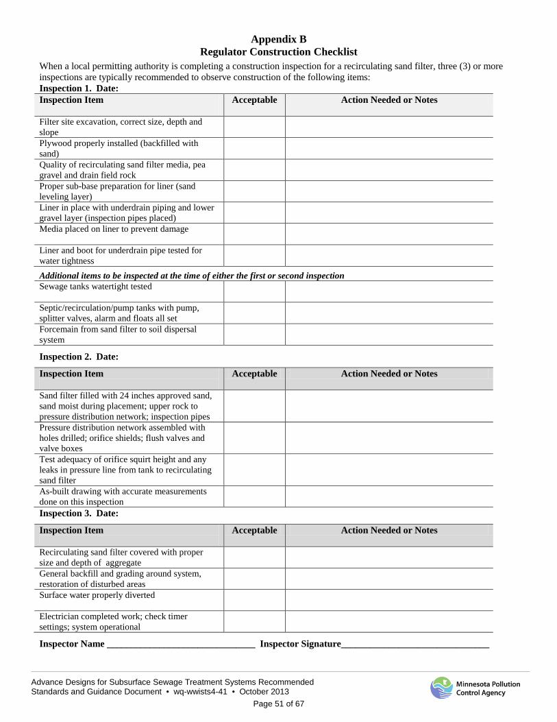
Advance Designs for Subsurface Sewage Treatment Systems Recommended Standards and Guidance Document • wq-wwists4-41 • October 2013
Page 51 of 67
Appendix B Regulator Construction Checklist
When a local permitting authority is completing a construction inspection for a recirculating sand filter, three (3) or more inspections are typically recommended to observe construction of the following items: Inspection 1. Date: Inspection Item
Acceptable Action Needed or Notes
Filter site excavation, correct size, depth and slope
Plywood properly installed (backfilled with sand)
Quality of recirculating sand filter media, pea gravel and drain field rock
Proper sub-base preparation for liner (sand leveling layer)
Liner in place with underdrain piping and lower gravel layer (inspection pipes placed)
Media placed on liner to prevent damage
Liner and boot for underdrain pipe tested for water tightness
Additional items to be inspected at the time of either the first or second inspection Sewage tanks watertight tested
Septic/recirculation/pump tanks with pump, splitter valves, alarm and floats all set
Forcemain from sand filter to soil dispersal system
Inspection 2. Date:
Inspection Item
Acceptable Action Needed or Notes
Sand filter filled with 24 inches approved sand, sand moist during placement; upper rock to pressure distribution network; inspection pipes
Pressure distribution network assembled with holes drilled; orifice shields; flush valves and valve boxes
Test adequacy of orifice squirt height and any leaks in pressure line from tank to recirculating sand filter
As-built drawing with accurate measurements done on this inspection
Inspection 3. Date:
Inspection Item
Acceptable Action Needed or Notes
Recirculating sand filter covered with proper size and depth of aggregate
General backfill and grading around system, restoration of disturbed areas
Surface water properly diverted
Electrician completed work; check timer settings; system operational
Inspector Name _______________________________ Inspector Signature_______________________________

Advance Designs for Subsurface Sewage Treatment Systems Recommended Standards and Guidance Document • wq-wwists4-41 • October 2013
Page 52 of 67
Appendix C Management Plan
Recirculating Sand Filter Fixed Film Treatment System
Flows ≤10,000 gpd and Domestic Strength Waste This Management Plan identifies some of the basic requirements for proper operation and maintenance of the Recirculating Sand Filter (RSF) wastewater treatment device for residential use. Refer to the Operation & Maintenance Manual for detailed instructions on the proper system operation and maintenance. Refer to your soil treatment system management plan (below or above-grade) for additional management requirements.
The Operation & Maintenance Manual was developed by the Minnesota Pollution Control Agency (MPCA) and can be found at the MPCA’s Web site: www.pca.state.mn.us/programs/ists/productregistration.html.
Items not permitted in recirculating sand filters; See Appendix C, Known Limitations in System Use, in this document.
At the time of each service visit, Form 7-1: Media Filter should be completed. See the following website for this and other reporting forms for service providers: http://www.onsiteconsortium.org/omspchecklists.html
SYSTEM COMPONENT
TASK MINIMUM FREQUENCY
RESPONSIBLE PARTY
Recirculating Sand Filter with Flows less than 10,000 gpd and Domestic Strength Wastewater
Monitor alarm
On-going User & Service Provider
Monitor flow
Annually <1,500 gpd
Bi-Annually >1,500 gpd <5,000 gpd
Quarterly
>5,000 gpd <10,000 gpd
Service Provider
Check mechanical and electrical components Verify flow splitting devices are performing accurately & adjust as needed Check for excessive odor and verify proper ventilation Check distribution system, flush and clean as needed Verify recirculation ratios and adjust as needed. Check for biomat and ponding in filter Perform operational field tests on influent/effluent quality including odor, color, turbidity, temperature, and pH as appropriate Sample effluent as required in the local Operating Permit*
See Operating Permit and Table on following page
For seasonal use, follow MPCA guidelines As required based on seasonal usage
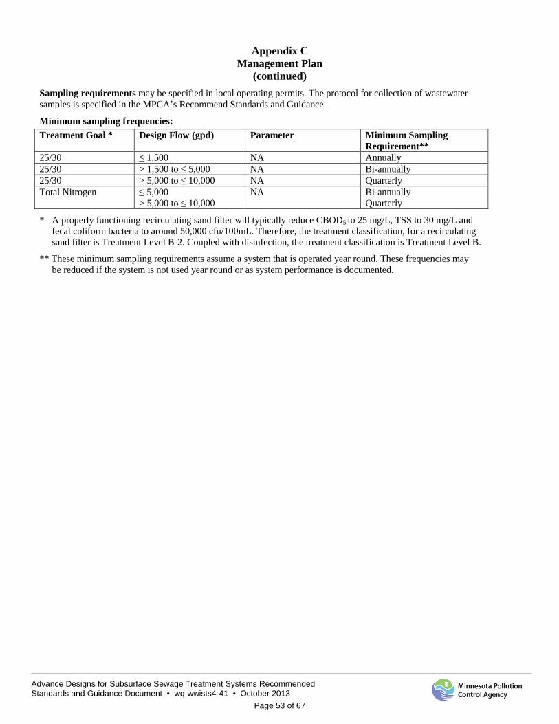
Advance Designs for Subsurface Sewage Treatment Systems Recommended Standards and Guidance Document • wq-wwists4-41 • October 2013
Page 53 of 67
Appendix C
Management Plan (continued)
Sampling requirements may be specified in local operating permits. The protocol for collection of wastewater samples is specified in the MPCA’s Recommend Standards and Guidance.
Minimum sampling frequencies: Treatment Goal * Design Flow (gpd) Parameter Minimum Sampling
Requirement** 25/30 ≤ 1,500 NA Annually 25/30 > 1,500 to ≤ 5,000 NA Bi-annually 25/30 > 5,000 to ≤ 10,000 NA Quarterly Total Nitrogen ≤ 5,000
> 5,000 to ≤ 10,000 NA Bi-annually
Quarterly
* A properly functioning recirculating sand filter will typically reduce CBOD5 to 25 mg/L, TSS to 30 mg/L and fecal coliform bacteria to around 50,000 cfu/100mL. Therefore, the treatment classification, for a recirculating sand filter is Treatment Level B-2. Coupled with disinfection, the treatment classification is Treatment Level B.
** These minimum sampling requirements assume a system that is operated year round. These frequencies may be reduced if the system is not used year round or as system performance is documented.
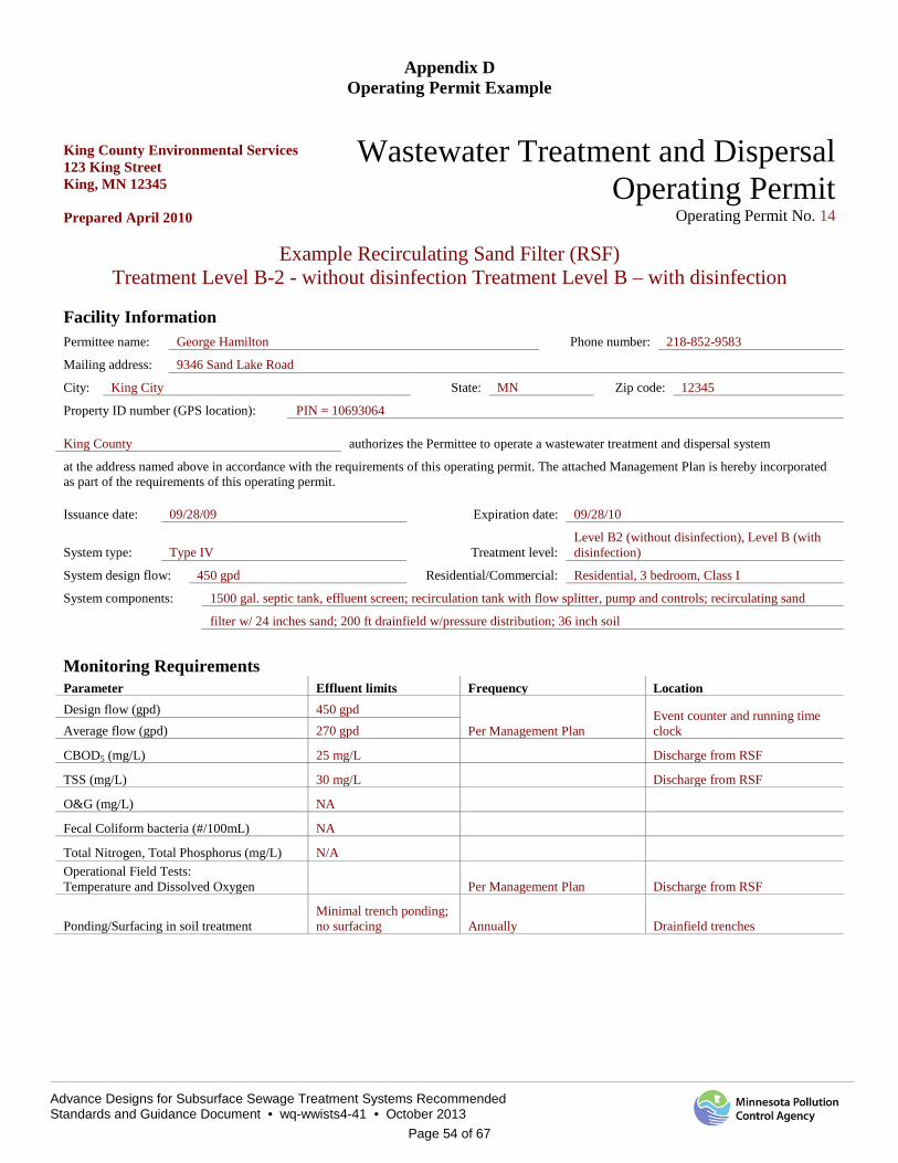
Advance Designs for Subsurface Sewage Treatment Systems Recommended Standards and Guidance Document • wq-wwists4-41 • October 2013
Page 54 of 67
Appendix D Operating Permit Example
King County Environmental Services 123 King Street King, MN 12345 Prepared April 2010
Wastewater Treatment and Dispersal Operating Permit
Operating Permit No. 14
Example Recirculating Sand Filter (RSF) Treatment Level B-2 - without disinfection Treatment Level B – with disinfection
Facility Information Permittee name: George Hamilton Phone number: 218-852-9583
Mailing address: 9346 Sand Lake Road
City: King City State: MN Zip code: 12345
Property ID number (GPS location): PIN = 10693064
King County authorizes the Permittee to operate a wastewater treatment and dispersal system
at the address named above in accordance with the requirements of this operating permit. The attached Management Plan is hereby incorporated as part of the requirements of this operating permit.
Issuance date: 09/28/09 Expiration date: 09/28/10
System type: Type IV Treatment level: Level B2 (without disinfection), Level B (with disinfection)
System design flow: 450 gpd Residential/Commercial: Residential, 3 bedroom, Class I
System components: 1500 gal. septic tank, effluent screen; recirculation tank with flow splitter, pump and controls; recirculating sand
filter w/ 24 inches sand; 200 ft drainfield w/pressure distribution; 36 inch soil
Monitoring Requirements Parameter Effluent limits Frequency Location Design flow (gpd) 450 gpd
Per Management Plan Event counter and running time clock Average flow (gpd) 270 gpd
CBOD5 (mg/L) 25 mg/L Discharge from RSF
TSS (mg/L) 30 mg/L Discharge from RSF
O&G (mg/L) NA
Fecal Coliform bacteria (#/100mL) NA
Total Nitrogen, Total Phosphorus (mg/L) N/A Operational Field Tests: Temperature and Dissolved Oxygen Per Management Plan Discharge from RSF
Ponding/Surfacing in soil treatment Minimal trench ponding; no surfacing Annually Drainfield trenches
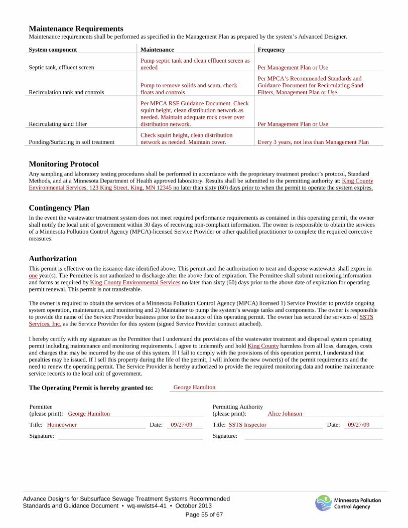
Advance Designs for Subsurface Sewage Treatment Systems Recommended Standards and Guidance Document • wq-wwists4-41 • October 2013
Page 55 of 67
Maintenance Requirements Maintenance requirements shall be performed as specified in the Management Plan as prepared by the system’s Advanced Designer.
System component Maintenance Frequency
Septic tank, effluent screen Pump septic tank and clean effluent screen as needed Per Management Plan or Use
Recirculation tank and controls Pump to remove solids and scum, check floats and controls
Per MPCA’s Recommended Standards and Guidance Document for Recirculating Sand Filters, Management Plan or Use.
Recirculating sand filter
Per MPCA RSF Guidance Document. Check squirt height, clean distribution network as needed. Maintain adequate rock cover over distribution network. Per Management Plan or Use
Ponding/Surfacing in soil treatment Check squirt height, clean distribution network as needed. Maintain cover. Every 3 years, not less than Management Plan
Monitoring Protocol Any sampling and laboratory testing procedures shall be performed in accordance with the proprietary treatment product’s protocol, Standard Methods, and at a Minnesota Department of Health approved laboratory. Results shall be submitted to the permitting authority at: King County Environmental Services, 123 King Street, King, MN 12345 no later than sixty (60) days prior to when the permit to operate the system expires.
Contingency Plan In the event the wastewater treatment system does not meet required performance requirements as contained in this operating permit, the owner shall notify the local unit of government within 30 days of receiving non-compliant information. The owner is responsible to obtain the services of a Minnesota Pollution Control Agency (MPCA)-licensed Service Provider or other qualified practitioner to complete the required corrective measures.
Authorization This permit is effective on the issuance date identified above. This permit and the authorization to treat and disperse wastewater shall expire in one year(s). The Permittee is not authorized to discharge after the above date of expiration. The Permittee shall submit monitoring information and forms as required by King County Environmental Services no later than sixty (60) days prior to the above date of expiration for operating permit renewal. This permit is not transferable. The owner is required to obtain the services of a Minnesota Pollution Control Agency (MPCA) licensed 1) Service Provider to provide ongoing system operation, maintenance, and monitoring and 2) Maintainer to pump the system’s sewage tanks and components. The owner is responsible to provide the name of the Service Provider business prior to the issuance of this operating permit. The owner has secured the services of SSTS Services, Inc. as the Service Provider for this system (signed Service Provider contract attached). I hereby certify with my signature as the Permittee that I understand the provisions of the wastewater treatment and dispersal system operating permit including maintenance and monitoring requirements. I agree to indemnify and hold King County harmless from all loss, damages, costs and charges that may be incurred by the use of this system. If I fail to comply with the provisions of this operation permit, I understand that penalties may be issued. If I sell this property during the life of the permit, I will inform the new owner(s) of the permit requirements and the need to renew the operating permit. The Service Provider is hereby authorized to provide the required monitoring data and routine maintenance service records to the local unit of government. The Operating Permit is hereby granted to: George Hamilton Permittee (please print): George Hamilton
Permitting Authority (please print): Alice Johnson
Title: Homeowner Date: 09/27/09 Title: SSTS Inspector Date: 09/27/09
Signature: Signature:
Advance Designs for Subsurface Sewage Treatment Systems Recommended Standards and Guidance Document • wq-wwists4-41 • October 2013
Page 56 of 67
Instructions for Completing an Operating Permit The following instructions provide an explanation for local units of government to complete the operating permit template. This is intended to provide guidance to local units of governments (LGU) in developing operating permits for Type IV Type V systems and MSTS, including both residential and commercial systems. Since the Management Plan is considered part of the operating permit, it needs to be attached to the operating permit. A signed contract, between the owner and Service Provider, should be attached to the operating permit to help ensure the owner has made the necessary arrangements to have the system maintained and monitored. LGU Name, Department and Address – fill in the name, department and address of local unit of government at the top of the operating permit. Wastewater Treatment and Dispersal Operating Permit No. – assign an operating permit number to be able to track the system over the years. Permittee Name, Business Name, Telephone Number, and Address – fill in the name, address and phone number of the owner. If this is a business, fill in the name of the business, too. Property Id. Number (GPS Location) – these are simply identifiers used by local units of government in the event the property address changes over time. Name of Local Unit of Government – fill in the name of the local unit of government. This authorizes the Permittee to operate the wastewater treatment system at the address named above, according to the operating permit, attached Management Plan and contract with the Service Provider. Issuance Date – fill in the date the operating permit is issued. The operating permit should not be issued until all required information is submitted. Expiration Date – fill in the date when this operating permit expires. The first time an operating permit is issued to an owner, it should be issued for one (1) year. This helps ensure the owner actually does the required maintenance and monitoring during the first year. If the owner complies, the operating permit can then be issued for a longer period of time as determined by the local unit of government (typically 3 to 5 years). However, if the owner does not comply the first year, the second operating permit could, again, be issued for a period of one (1) year. System Type – fill in as Type IV system, Type V system or MSTS. Treatment Level – specify Treatment Level A, A-2,B, B-2, C, TN or TP. Treatment Level A = Carbonaceous Biochemical Oxygen Demand, five day (CBOD5) 15 milligrams per liter (mg/L), Total Suspended Solids (TSS) 15 mg/L, Fecal Coliform Bacteria 1000 per 100 milliliter (mL); Treatment Level A-2 = Carbonaceous Biochemical Oxygen Demand, five day (CBOD5) 15 milligrams per liter (mg/L), Total Suspended Solids (TSS) 15 mg/L, Fecal Coliform Bacteria - no limit; Treatment Level B = CBOD5 25 mg/L, TSS 30 mg/L, Fecal Coliform Bacteria 10,000 per 100 mL; Treatment Level B-2 = CBOD5 25 mg/L, TSS 30 mg/L, Fecal Coliform Bacteria – no limit; Treatment Level C = CBOD5 125 mg/L, TSS 60 mg/L, Oil and Grease (O&G) = 25 mg/L, Fecal Coliform Bacteria – no limit; Total Nitrogen (TN) = 20 mg/L or actual number, or Total Phosphorus (TP) = <5 mg/L or actual number. System Design Flow – fill in the design flow specified on the construction permit for the system, along with the projected average daily flow for the system. Average daily flow is generally 60 to 70 percent of design flow. Residential/Commercial – specify if the system is residential or commercial. You may specify additional information, such as classification of dwelling, number of bedrooms; or type of commercial establishment. System Components – provide a brief description of the system components. An example would be the following: 600 gallon trash tank, 600 gallon Brand X proprietary treatment device, 1 Brand Y Ultra Violet (UV) light disinfection unit, 500-gallon pump tank, pump, floats and controls, and 250-foot shallow trenches using pressure distribution.
Monitoring Requirements (Table)
The monitoring requirements specified in an operating permit are unique to the site and soil conditions of the property (its environmental sensitivity) and system complexity. The monitoring requirements include specific parameters to be monitored, target limits and the frequency and location of monitoring. The monitored parameters, at a minimum, would include: 1) wastewater flow - the most basic parameter to know in understanding system performance, 2) ponding in the soil treatment system and 3) surfacing of the soil treatment system. Monitoring for CBOD5, TSS, fecal coliform bacteria and nitrogen are unique to the site, its receiving environment and complexity of the wastewater system. Field tests for temperature, pH and dissolved oxygen can be performed by the Service Provider to serve as general indicators of system performance.
1. Flow – flow to each system needs to be determined as specified in the Management Plan or as determined by the local unit of government. Flow can be determined several ways, using water meters, event counters, and running time clocks. Telemetry can also be used and has the advantage that flow can be determined continually.
The determination for the frequency of flow measurement is done on a case-by-case basis. At first, daily flow monitoring may be needed to determine average flow and peak flows to a system. After a period of time, weekly or monthly flow determination may be acceptable. Flow determinations once a year generally provide limited information.
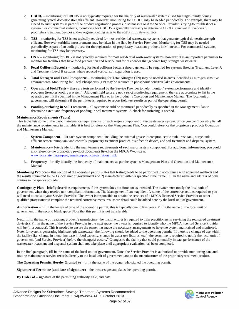
Advance Designs for Subsurface Sewage Treatment Systems Recommended Standards and Guidance Document • wq-wwists4-41 • October 2013
Page 57 of 67
2. CBOD5 – monitoring for CBOD5 is not typically required for the majority of wastewater systems used for single-family homes generating typical domestic strength effluent. However, monitoring for CBOD5 may be needed periodically. For example, there may be a need to audit systems as part of the product registration process in Minnesota or if the Service Provider is trying to troubleshoot a system. For commercial systems, monitoring for CBOD5 is generally necessary to determine CBOD5 removal efficiencies of proprietary treatment devices and/or organic loading rates to the soil’s infiltrative surface.
3. TSS – monitoring for TSS is not typically required for most residential wastewater systems that generate typical domestic strength effluent. However, turbidity measurements may be taken in the field by Service Providers. Monitoring for TSS may be needed periodically as part of an audit process for the registration of proprietary treatment products in Minnesota. For commercial systems, monitoring for TSS may be necessary.
4. O&G – monitoring for O&G is not typically required for most residential wastewater systems; however, it is an important parameter to monitor for facilities that have food preparation and service and for residences that generate high strength wastewater.
5. Fecal Coliform Bacteria – monitoring for fecal coliform bacteria should generally be required for systems listed as Treatment Level A and Treatment Level B systems where reduced vertical soil separation is used.
6. Total Nitrogen and Total Phosphorus – monitoring for Total Nitrogen (TN) may be needed in areas identified as nitrogen sensitive environments. Monitoring for Total Phosphorus (TP) may be required in phosphorus sensitive lake environments.
7. Operational Field Tests – these are tests performed by the Service Provider to help ‘monitor’ system performance and identify problems (troubleshooting a system). Although field tests are not a strict monitoring requirement, they are appropriate to list in the operating permit if specified in the Management Plan or in the product’s Operation and Maintenance Manual. The local unit of government will determine if the permittee is required to report field test results as part of the operating permit.
8. Ponding/Surfacing in Soil Treatment – all systems should be monitored periodically as specified in the Management Plan to determine extent and frequency of ponding in soil treatment systems. A check for surfacing is needed.
Maintenance Requirements (Table) This table lists some of the basic maintenance requirements for each major component of the wastewater system. Since you can’t possibly list all the maintenance requirements in this table, it is best to reference the Management Plan. You could reference the proprietary products Operation and Maintenance Manual.
1. System Component – list each system component, including the external grease interceptor, septic tank, trash tank, surge tank, effluent screen, pump tank and controls, proprietary treatment product, disinfection device, and soil treatment and dispersal system.
2. Maintenance – briefly identify the maintenance requirements of each major system component. For additional information, you could also reference the proprietary product documents listed on the MPCA Web site at www.pca.state.mn.us/programs/ists/productregistration.html.
3. Frequency – briefly identify the frequency of maintenance as per the systems Management Plan and Operation and Maintenance Manual.
Monitoring Protocol – this section of the operating permit states that testing needs to be performed in accordance with approved methods and the results submitted to the 1) local unit of government and 2) manufacturer within a specified time frame. Fill in the name and address of both entities in the spaces provided. Contingency Plan – briefly describes requirements if the system does not function as intended. The owner must notify the local unit of government when they receive non-compliant information. The Management Plan may identify some of the corrective actions required or you will need to consult your Service Provider. The owner is responsible to obtain the services of a MPCA-licensed Service Provider or other qualified practitioner to complete the required corrective measures. More detail could be added here by the local unit of government. Authorization – fill in the length of time of the operating permit; this is typically one to five years. Fill in the name of the local unit of government in the second blank space. Note that this permit is not transferable. Next, fill in the name of treatment product’s manufacture; the manufacturer is required to train practitioners in servicing the registered treatment device(s). Fill in the name of the Service Provider in the next space; the owner is required to identify who the MPCA licensed Service Provider will be (in a contract). This is needed to ensure the owner has made the necessary arrangements to have the system maintained and monitored. Note: for systems generating high strength wastewater, the following should be added to the operating permit: “If there is a change of use within the facility (i.e. change in menu, increase in food capacity, change in water use fixtures, etc.), the permittee is required to notify the local unit of government (and Service Provider) before the change(s) occurs.” Changes to the facility that could potentially impact performance of the wastewater treatment and dispersal system shall not take place until appropriate evaluation has been completed. In the final paragraph, fill in the name of the local unit of government. Note: the Service Provider is authorized to provide monitoring data and routine maintenance service records directly to the local unit of government and to the manufacturer of the proprietary treatment product. The Operating Permits Hereby Granted to – print the name of the owner who signed the operating permit. Signature of Permittee (and date of signature) – the owner signs and dates the operating permit. By Order of – signature of the permitting authority, title, and date
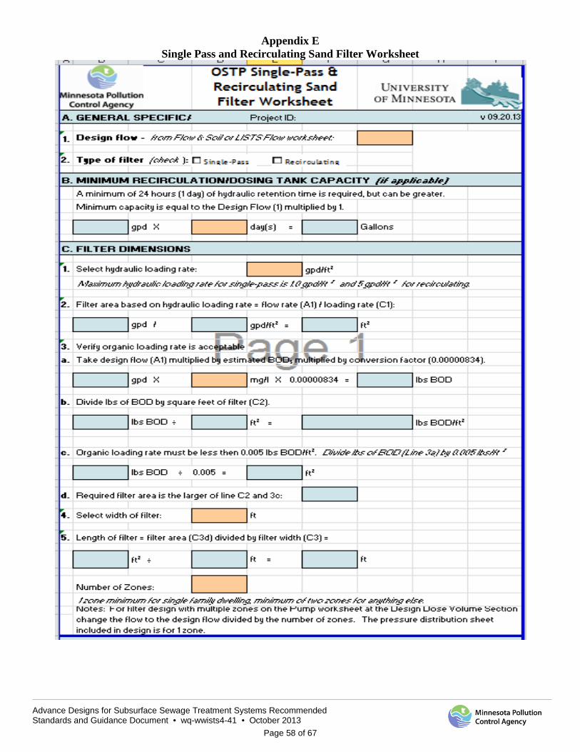
Advance Designs for Subsurface Sewage Treatment Systems Recommended Standards and Guidance Document • wq-wwists4-41 • October 2013
Page 58 of 67
Appendix E Single Pass and Recirculating Sand Filter Worksheet
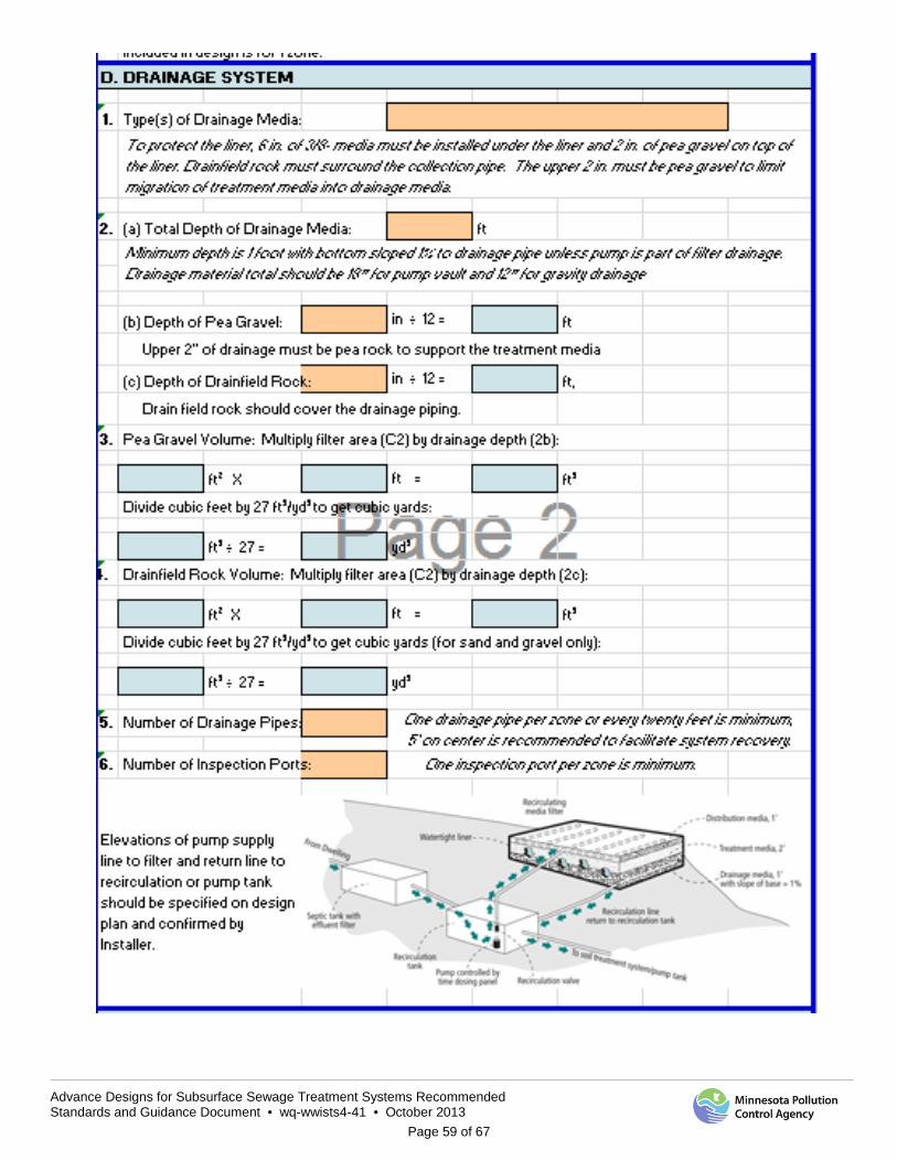
Advance Designs for Subsurface Sewage Treatment Systems Recommended Standards and Guidance Document • wq-wwists4-41 • October 2013
Page 59 of 67

Advance Designs for Subsurface Sewage Treatment Systems Recommended Standards and Guidance Document • wq-wwists4-41 • October 2013
Page 60 of 67
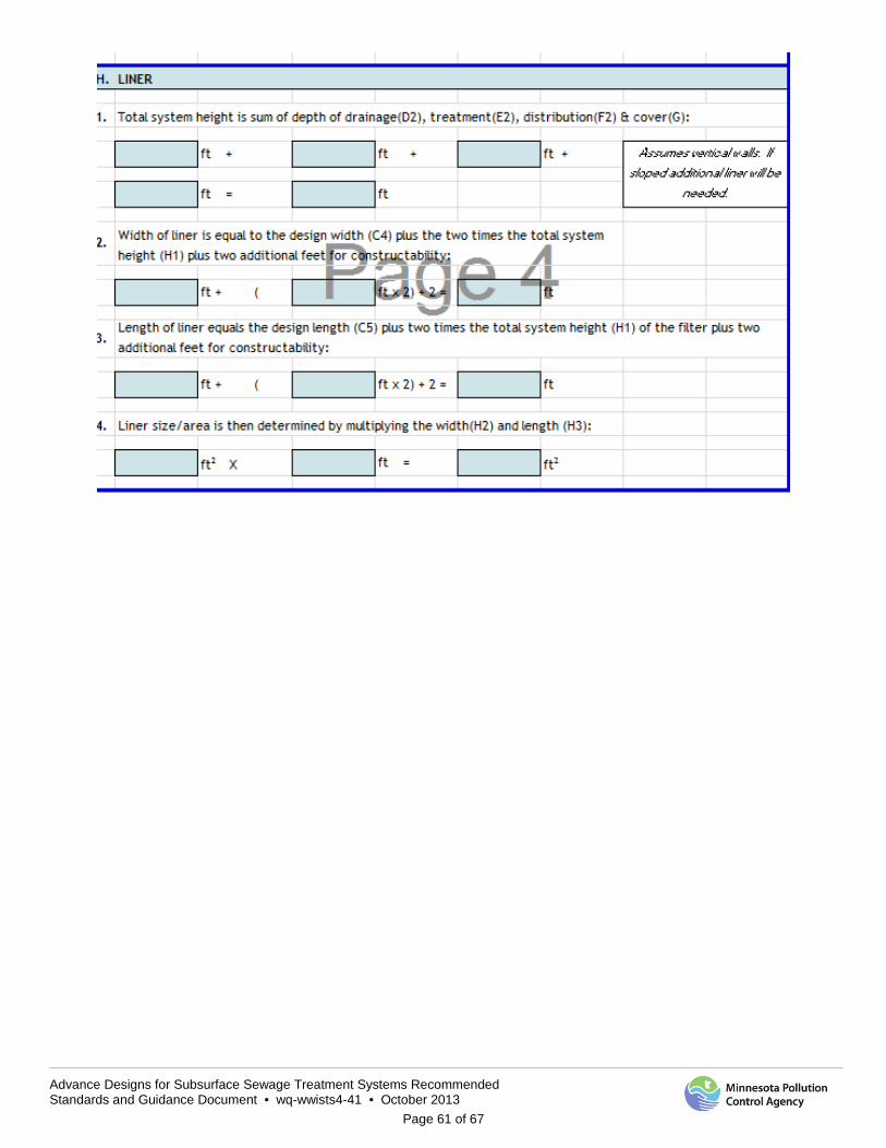
Advance Designs for Subsurface Sewage Treatment Systems Recommended Standards and Guidance Document • wq-wwists4-41 • October 2013
Page 61 of 67

Advance Designs for Subsurface Sewage Treatment Systems Recommended Standards and Guidance Document • wq-wwists4-41 • October 2013
Page 62 of 67
Appendix F Pressure Distribution Worksheet
Width of one zone
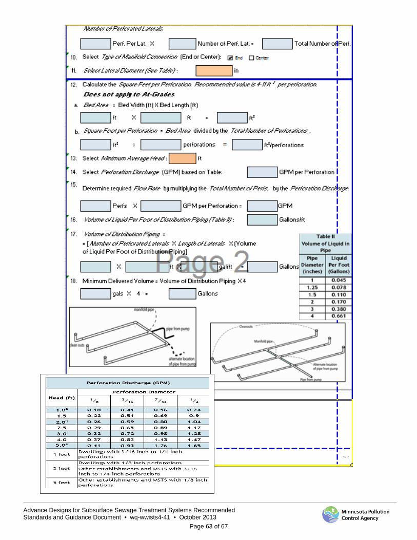
Advance Designs for Subsurface Sewage Treatment Systems Recommended Standards and Guidance Document • wq-wwists4-41 • October 2013
Page 63 of 67
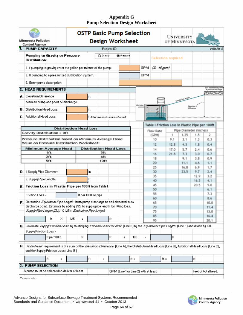
Advance Designs for Subsurface Sewage Treatment Systems Recommended Standards and Guidance Document • wq-wwists4-41 • October 2013
Page 64 of 67
Appendix G Pump Selection Design Worksheet
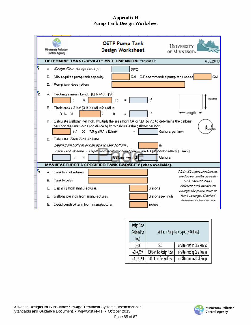
Advance Designs for Subsurface Sewage Treatment Systems Recommended Standards and Guidance Document • wq-wwists4-41 • October 2013
Page 65 of 67
Appendix H Pump Tank Design Worksheet
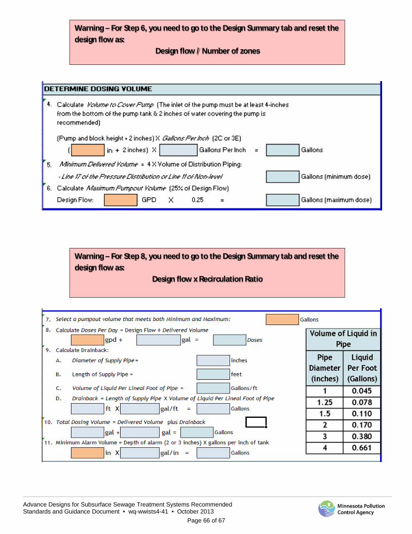
Advance Designs for Subsurface Sewage Treatment Systems Recommended Standards and Guidance Document • wq-wwists4-41 • October 2013
Page 66 of 67
Warning – For Step 6, you need to go to the Design Summary tab and reset the design flow as:
Design flow / Number of zones
Warning – For Step 8, you need to go to the Design Summary tab and reset the design flow as:
Design flow x Recirculation Ratio
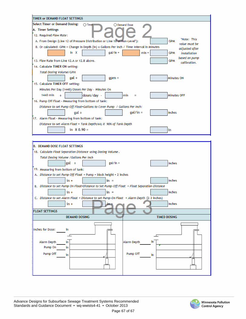
Advance Designs for Subsurface Sewage Treatment Systems Recommended Standards and Guidance Document • wq-wwists4-41 • October 2013
Page 67 of 67