Embed Size (px)
Citation preview

MODELS P324, VP324, P325(B) AND VP325(B) NATURAL GAS
B-VENT DECORATIVE GAS FIREPLACEOWNER’S OPERATION AND INSTALLATION MANUAL
For more information, visit www.fmiproducts.com
WARNING: If the information in this manual is not followed exactly, a fire or explosion may result causing property damage, personal injury or loss of life.
— Do not store or use gasoline or other flammable vapors and liquids in the vicinity of this or any other appliance.
— WHAT TO DO IF YOU SMELL GAS• Do not try to light any appliance.• Do not touch any electrical switch; do not use any
phone in your building.• Immediately call your gas supplier from a neighbor’s
phone. Follow the gas supplier’s instructions.• If you cannot reach your gas supplier, call the fire
department.— Installation and service must be performed by a quali-
fied installer, service agency or the gas supplier.
INSTALLER: Leave this manual with the appliance.CONSUMER: Retain this manual for future reference.
PFS ®
US

www.fmiproducts.com 108660-01G2
SAFETy
WARNING: Improper instal-lation, adjustment, alteration, service or maintenance can cause injury or property damage. Refer to this manual for correct installation and operational procedures. For assistance or additional information consult a qualified installer, service agency or the gas supplier.
This appliance may be installed in an aftermarket,* permanently located, manufactured (mobile) home, where not prohibited by local codes.This appliance is only for use with the type of gas indicated on the rating plate. This appliance is not convertible for use with other gases, unless a certified kit is used.
* Aftermarket: Completion of sale, not for purpose of resale, from the manufacturer
NOT FOR USE WITH SOLID FUEL
CHECK LOCAL CODES PRIOR TO INSTALLATION
SAVE THIS BOOKThis book is valuable. In addi-tion to instructing you on how to install and maintain your appliance, it also contains in-formation that will enable you to obtain replacement parts or optional accessory items when needed. Keep it with your other important papers.
State of Massachusetts: The installation must be made by a licensed plumber or gas fitter in the Commonwealth of Mas-sachusetts.
TABLE OF CONTENTSSafety .................................................................. 2Unpacking............................................................ 4Introduction .......................................................... 4Product Specification ........................................... 6Selecting Location ............................................... 7PreInstallation Preparation .................................. 7Venting Installation .............................................. 9Installation ..........................................................11Operation ........................................................... 19Inspecting Burners............................................. 20
Cleaning and Maintenance ................................ 21Troubleshooting ................................................. 22Replacement Parts ............................................ 25Service Hints ..................................................... 25Technical Service............................................... 25Accessories ....................................................... 25Parts .................................................................. 26Wiring Diagram .................................................. 31Warranty ..............................................Back Cover

www.fmiproducts.com108660-01G 3
WARNING: This product contains and/or generates chemicals known to the State of California to cause cancer or birth defects or other reproduc-tive harm.
IMPORTANT: Read this owner’s manual carefully and completely before trying to assemble, op-erate or service this fireplace. Improper use of this fireplace can cause serious injury or death from burns, fire, explosions, electrical shock and carbon monoxide poisoning.
DANGER: Carbon monoxide poisoning may lead to death!
This fireplace is a vented product. This fire-place will not produce any gas leakage into your home if properly installed. This fireplace must be properly installed by a qualified service person. If this unit is not properly installed by a qualified service person, gas leakage can occur.Carbon Monoxide Poisoning: Early signs of carbon monoxide poisoning resemble the flu, with headaches, dizziness or nausea. If you have these signs, the fireplace may not have been installed properly. Get fresh air at once! Have fireplace inspected and serviced by a qualified service person. Some people are more affected by carbon monoxide than oth-ers. These include pregnant women, people with heart or lung disease or anemia, those under the influence of alcohol and those at high altitudes.Propane/LP and Natural Gas: Both are odor-less. An odor-making agent is added to each of these gases. The odor helps you detect a gas leak. However, the odor added to these gases can fade. Gas may be present even though no odor exists.Make certain you read and understand all warnings. Keep this manual for reference. It is your guide to safe and proper operation of this fireplace.
WARNING: Any change to this fireplace or its controls can be dangerous.
1. This appliance is only for use with the type of gas indicated on the rating plate. This appliance is not convertible for use with other gases unless a certified kit is used.
2. For propane/LP fireplace, do not place propane/LP supply tank(s) inside any structure. Locate propane/LP supply tank(s) outdoors. To prevent performance problems, do not use propane/LP fuel tank of less than 100 lb capacity.
3. If you smell gas• shut off gas supply• do not try to light any appliance• do not touch any electrical switch; do not
use any phone in your building• immediately call your gas supplier from
a neighbor’s phone. Follow the gas sup-plier's instructions
• if you cannot reach you gas supplier, call the fire department.
4. Never install the fireplace • in a recreational vehicle• where curtains, furniture, clothing or
other flammable objects are less than 42" from the front, top or sides of the fireplace
• in high traffic areas• in windy or drafty areas
5. This fireplace reaches high temperatures. Keep children and adults away from hot surfaces to avoid burns or clothing igni-tion. Fireplace will remain hot for a time after shutdown. Allow surfaces to cool before touching.
6. Carefully supervise young children when they are in the room with fireplace.
7. A hearth extension is not required with this appliance. If one is installed, it is for aes-thetic purposes only and does not have to meet the standard requirements.
8. Turn fireplace off and let cool before ser-vicing or repairing. Only a qualified service person should install, service or repair this fireplace. Have fireplace inspected annually by a qualified service person.
SAFETyContinued

www.fmiproducts.com 108660-01G4
9. You must keep control compartments, burners and circulating air passages clean. More frequent cleaning may be needed due to excessive lint and dust from carpeting, bedding material, etc. Turn off the gas valve and pilot light before cleaning fireplace.
10. Have venting system inspected annually by a qualified service person. If needed, have venting system cleaned or repaired. See Cleaning and Maintenance, page 21.
11. Keep the area around your fireplace clear of combustible materials, gasoline and other flammable vapor and liquids. Do not run fireplace where these are used or stored. Do not place items such as clothing or decorations on or around fireplace.
12. Do not use this fireplace to cook food or burn paper or other objects.
13. Do not use any solid fuels (wood, coal, paper, cardboard, etc.) in this fireplace. Use only the gas type indicated on fire-place nameplate.
SAFETyContinued
14. This appliance, when installed, must be electrically grounded in accordance with local codes or, in the absence of local codes, with the National Electrical Code, ANSI/NFPA 70.
15. Do not install fireplace directly on carpet-ing, vinyl tile or any combustible material other than wood. The fireplace must set on a metal or wood panel extending the full width and depth of the fireplace.
16. Do not use fireplace if any part has been exposed to or under water. Immediately call a qualified service person to arrange for replacement of the unit.
17. Do not operate fireplace if any log is broken.
18. Do not use a blower insert, heat exchang-er insert or other accessory not approved for use with this fireplace.
19. Provide adequate clearances around air openings.
UNPACkINGThe following items are packed inside the firebox. Remove before positioning firebox into framing.• Ceramic Log Pack - Shrink wrapped on
cardboard• 3 plastic bags containing lava rock, pan and
ember materials
• Rear Log (P325/VP325 Models Only). Remove 2 plastic quick ties from around burner and grate
• Grate Stand - Lift off of burner panCheck all items for any shipping damage. If damaged, promptly inform dealer or distributor where you bought the product.Retain these items for later installation.
INTRODUCTIONThese fireplace models are vented gas fire-places that use a millivolt gas control valve with a millivolt ignition system. P325/VP325 models have a 5" B-vent and P324/VP324 models have a 4" B-vent. A properly sized B-Type venting system and listed type vent cap are not supplied but are required for proper operation. See venting instructions on page 9.
WARNING: This gas appli-ance must not be connected to a chimney flue servicing a solid fuel burning appliance.
These models are factory equipped for use with natural gas and must be converted when intended for use with propane/LP gas. Conversion kits PCBM-324 and PCBM-325 may be purchased for simple conversion to propane/LP gas. See Accessories, page 25.
BEFORE YOU BEGINBefore beginning the installation of your appli-ance, read these instructions completely.This FMI PRODUCTS, LLC appliance and its approved components are safe when installed according to this installation manual and are operated as recommended by FMI PRODUCTS, LLC. Using any component fon FMI PROD-UCTS, LLC approved and tested for use with this appliance MAY CAUSE A FIRE HAZARD!

www.fmiproducts.com108660-01G 5
The FMI PRODUCTS, LLC warranty will be voided by, and FMI PRODUCTS, LLC disclaims any responsibility for the following actions:A) Modification of the appliance or any of the
components.B) Use of any component part not approved
by FMI PRODUCTS, LLC in combination with this appliance.
C) Installation and/or operation in a manner other than instructed in this manual.
D) The burning of anything other than the type of gas approved for use in this gas appliance.
Installation must conform with local codes or, in the absence of local codes, with the current National Fuel Gas Code, ANSI Z223.1. This appliance complies with ANSI Z21.50.
NOTICE: This appliance is not intended to be used as a primary source of heat.
WARNING: Installation of this appliance should be done by a qualified service person well trained in the installation of such appliances. You will also need a building permit from your local Building and Safety Commissioner before installing this appliance; otherwise your insurance co. may not cover this appliance.
INTRODUCTIONContinued
CAUTION: Do not connect appliance before pressure test-ing gas piping. Damage to gas valve may result and an unsafe condition may be caused.
The appliance and it’s individual shutoff valve must be disconnected from the gas supply piping system during any pressure testing of that system at test pressures in excess of 1/2 psig (3.5 kPa).The appliance must be isolated from the gas supply piping system by closing its individual manual shutoff valve during any pressure testing of the gas supply piping system at test pressures equal to or less than 1/2 psig (3.5 kPa).For the purpose of input adjustment two pressure taps (for IN and OUT pressures) are provided on the gas control valve for test gauge connections to the appliance.+
www.fmiproducts.com 108660-01G6
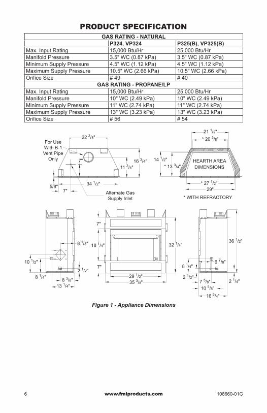
PRODUCT SPECIFICATIONGAS RATING - NATURAL
P324, VP324 P325(B), VP325(B)Max. Input Rating 15,000 Btu/Hr 25,000 Btu/HrManifold Pressure 3.5" WC (0.87 kPa) 3.5" WC (0.87 kPa)Minimum Supply Pressure 4.5" WC (1.12 kPa) 4.5" WC (1.12 kPa)Maximum Supply Pressure 10.5" WC (2.66 kPa) 10.5" WC (2.66 kPa)Orifice Size # 49 # 40
GAS RATING - PROPANE/LPMax. Input Rating 15,000 Btu/Hr 25,000 Btu/HrManifold Pressure 10" WC (2.49 kPa) 10" WC (2.49 kPa)Minimum Supply Pressure 11" WC (2.74 kPa) 11" WC (2.74 kPa)Maximum Supply Pressure 13" WC (3.23 kPa) 13" WC (3.23 kPa)Orifice Size # 56 # 54
6 7/8"
2 1/4"
7"
7"
Alternate GasSupply Inlet
13 1/4"
32 1/4"
* 27 1/2"29"
* 13 3/4"
14 1/2"
* 20 3/8"
21 1/2"
2 1/2"
8 1/4"
11 3/4"
22 3/8"For UseWith B-1Vent Pipe
Only 16 3/4"
7 5/8"10 5/8"
8 1/8"
10 1/2"
8 3/8"
2 1/2"8 1/4"
5/8"34 1/2"
35 3/8"29 1/2"
18 1/4"
7"
7"
16 3/4"
36 1/2"
* WITH REFRACTORY
DIMENSIONSHEARTH AREA
Figure 1 - Appliance Dimensions

www.fmiproducts.com108660-01G 7
Figure 2 - Possible Locations for Installing Fireplace
INTERNAL WALLINSTALLATION
CORNERINSTALLATION
FULLPROJECTIONINSTALLATION
FLUSHINSTALLATION
PREINSTALLATION PREPARATION
Figure 3 - Minimum Clearances (Top View)
0"
0" Clearance
Nailing Flange
Front FaceLeft Side Surround
Back
Drywall
2 x 4 Stud
SELECTING LOCATIONTo determine the safest and most efficient location for your appliance, you must take into consideration the following guidelines:1. The location must allow for proper clear-
ances (see Clearances).2. Consider a location where heat output
would not be affected by drafts, air con-ditioning ducts, windows, or doors.
3. A location that avoids the cutting of joists or roof rafters will make installation easier. Figure 2 shows a plan view of a few com-mon locations.
Flush installations are recommended where living space is limited or at a premium, and since the space required to enclose the ap-pliance would be located beyond an outside wall, this would also reduce the cutting of joists, roof rafters, and such. Check local codes for any restrictions.
Projected installations can extend any distance into the room. A projection may be ideal for a new addition on an existing, finished wall.Corner installations make use of space that may not normally be used and provides a wider and more efficient range for radiant heat transference.Internal wall installations provide a discreet option for room separation and can also be ideal as an addition to an existing wall.
CLEARANCESMinimum clearances to combustibles are:Top of Spacers 0" min.Back and Sides of Outer Surround 0" min.Drywall to Sides of Front Face (Nailing Flanges) 0" min.“B” Vent Surfaces 1" min.Ceiling to Opening 42" min.Floor 0" min.Perpendicular Wall See Figure 6, page 8
CAUTION: Do not block required air spaces with insu-lation or any other material. Do not obstruct effective opening of appliance with any type of facing material.

www.fmiproducts.com 108660-01G8
PRE-INSTALLATION PREPARATIONContinued
MANTEL CLEARANCES AND WALL DETAILSA combustible mantle shelf maybe installed a maximum 12" (22.9 cm) from the wall. Figures 5 and 6 show the minimum allowable distances from various combustible mantle components in relation to the fireplace opening.
Spacer
3" (7.6 cm)
1 1/2" (3.8 cm) Max.
8" (20.3 cm)
6" (15.2 cm)
13" (33 cm)
12"(22.9 cm)
CombustibleMaterials
Header
Figure 5 - Mantel Clearances - Side View (Cross Section)
1 1/2" (3.8 cm)Max.
3" (7.6 cm)Max.
6" (15.2 cm)Max. 9"
(22.86 cm)12"
(30.48 cm)
Outer Surround
CombustibleMaterial MayBe Used
TOP VIEW
SAFEZONE
PerpendicularWall
Figure 6 - Side Clearances - Top View (Cross Section)
Figure 4 - Minimum Clearances (Front View)
* ***
42" (10.67 cm)Min. Clearancefrom Opening to Ceiling
0" Clearance
Ceiling
1" (2.5 cm) Min.Clearance to "B" Vent's Outer Pipe
RequiredAir Spaces are Indicated with an "*". Do Not Pack with Insulation or Any Other Material
DO NOT BLOCKOR OBSTRUCT
OPENINGS0" Clearance to Wood or NoncombustibleFlooring

www.fmiproducts.com108660-01G 9
PRE-INSTALLATION PREPARATIONContinued
FRAMING1. Frame appliance enclosure as illustrated
in Figures 7 and 8. Note: If a wall covering is used to line the
enclosure, then all measurements must be from the surface of the covering.
2. Place the appliance into the framing and secure it.
Note: If appliance is to be raised above floor level, a platform must be built to support the appliance.
3. Install the supply line to the appliance using a 1/2" NPT black iron gas line ter-minating 2 5/16" above the bottom of the appliance. The gas line may be installed from either side or from the rear of the appliance (see Figure 18, page 13).
4. Feed flexible gas line through one of three gas line conduit sleeves and repack insu-lation to cover any openings. Prepare the incoming gas line with Teflon tape or pipe joint compound and hookup incoming gas line to flexible gas line.
Figure 7 - Rough Opening for Installing in Wall
16 1/8"
34 3/4"
36 5/8"
Figure 8 - Corner Installation Guidelines
16 3/4"
12"
39 3/8"
55 5/8"34 1/2"
16"
These Dimensions Allow for a 3/4" Clearance at Sides and Back of Fireplace. 0" Clearance is Permitted
3/4" Clearance Not Required at Nailing Flanges
Note: If 1/2" NPT black iron pipe does not mate with fitting at the end of flexible gas line, remove fitting and replace with a 37 degree flare 3/4"-12, 1/2" NPT (female) fitting.
WARNING: When finishing appliance, do not overlap com-bustible material onto the black front face. Brick, tile, or other noncombustible materials may be applied to the face provided that any gap is between the material used and the face is caulked with a noncombustible caulking.
VENTING INSTALLATIONA B-type venting system must be connected to the appliance for venting to the outside of the building.The following section is provided as a guide to a standard B-type vent installation.Standing codes requirements concerning B-type vent installations may vary within your state, province or local codes jurisdiction. Therefore, it is recommended that you check with your local building codes for specific requirements or in absence of local codes, follow Section 7.0 of the current National Fuel Gas Code NFPA No. 54/ANSI Z223.1.
This gas appliance must be vented to the outdoors only and may not be terminated into an attic space or into a chimney flue servicing a solid fuel burning appliance.This appliance may be vented through a manufactured chimney system or a masonry chimney using a B-vent adapter or a chim-ney liner system if all are listed, inspected and approved by local codes and/or building authorities.The examples shown in Figure 9, page 10 are typical of most B-vent installations and code practices.

www.fmiproducts.com 108660-01G10
Figure 9 - Typical B-Vent Configuration
MaintainListedClearance
12' Min.
45°6'
8'
12' Min.
60° 45°
PositionFirestop
PositionFirestop
ListedVent Cap
Listed Vent Cap
MaintainListedClearance
MaintainListedClearance
MaintainListedClearance
Support Each
Lateral At Least
Every6 Feet
MaintainListedClearance
EXAMPLE 2EXAMPLE 1
MaintainListedClearance
12' Min.
45°PositionFirestop
ListedVent Cap
MaintainListedClearance
10'
EXAMPLE 3
Example 1 shows the minimum allowable system height and lateral offset for a 60° or greater inclination. Code specifies that offsets at 60° or greater are considered horizontal and must follow the 75% rule for lateral to total vertical system height. Codes also al-lows only one offset in the total system when at 60° or greater. The total vertical height in this example represents the minimum height of 8 feet and therefore the allowable lateral is 6 feet when the 75% rule applies. If the lateral length must exceed 75% then the system must be sized in accordance with the Category I venting tables.Example 2 shows a multiple offset each at 45° of inclination. Multiple offsets are permitted if they do not exceed 45° of inclination. The total lengths of the two offsets are not required to meet the 75% allowable rule.Example 3 shows a single offset at 45° of inclination and therefore the lateral length at 10 feet of offset does not have to meet the 75% rule.In each case the offsets must be supported and firestops must be positioned wherever the vent must pass through a subfloor, ceil-ing joist or an attic overhang. The vent pipe must terminate vertically into a listed type vent cap and extend a sufficient height through an approved roof flashing, roof jack or a roof thimble. At all points the listed clearances must be maintained.Vent terminations must be located in ac-cordance with height and proximity rules of
LowestDischargeOpening
ListedVent Cap
8 Ft. Min.
Roof Pitch x/12Listed Clearance
12
xListedGasVent
H (Min)HeightFrom Roof
Roof Pitch H (Min.) Ft. mFlat to 6/12 1.0 0.306/12 to 7/12 1.25 0.38Over 7/12 to 8/12 1.5 0.46Over 8/12 to 9/12 2.0 0.61Over 9/12 to 10/12 2.5 0.76Over 10/12 to 11/12 3.25 0.99Over 11/12 to 12/12 4.0 1.22Over 12/12 to 14/12 5.0 1.52Over 14/12 to 16/12 6.0 1.83Over 16/12 to 18/12 7.0 2.13Over 18/12 to 20/12 7.5 2.27Over 20/12 to 21/12 8.0 2.44
Figure 10 - B-Vent Terminations
VENTING INSTALLATIONContinued
NFPA No. 54. These rules apply to vents at 12" diameter or less and require a minimum height in accordance with the roof pitch and a minimum of 8 feet distance from a vertical wall or obstruction (see Figure 10).If venting horizontally through a side wall be-comes necessary, a listed thimble approved for use with B-type vent must be used. Check with your local codes before venting through a side wall.

www.fmiproducts.com108660-01G 11
VENTING INSTALLATIONContinued
Some codes areas allow the use of existing B-type vent systems if the system is at or above the recommended diameter of the flue.The flue connection must be made using listed B-type connectors and the existing system must be code inspected for damage and proper installation.It is not recommended that this appliance be common vented with an existing gas burning appliance. However, if it becomes necessary to common vent this appliance, the venting system must be sized and configured in ac-cordance with the common venting guides Appendix G of the current National Fuel Gas Code NFPA No. 54/ANSI Z223.1.Note: Before connecting this appliance to an existing vent system or a common venting system consult with your local architect, plan-ner, or building official.
WARNING: This appliance must be properly connected to a system and must not be connected to a chimney flue servicing a separate solid fuel burning appliance.
CHECKING FOR PROPER VENTINGAfter completing and checking the electrical, gas and vent connections, follow the lighting instructions and allow the main burner to run for approximately 5 minutes. Hold a lit match or cigarette near top edge of fireplace opening and play it along entire length of the opening (see Figure 11). Proper venting should tend to draw flame or smoke into appliance. Improper venting or escaping of spillage of burned gas, is indicated when match flickers or goes out. Smoke from a cigarette will also tend to disperse away from the appliance.
If appliance is found to be improperly venting, shut it off and notify your installer or a qualified service agency to inspect venting system.
NOTICE: This appliance is equipped with a vent safety shutoff switch which will shut down appliance in case of a venting problem. Do not bypass vent safety switch. If appliance should shut down, contact a qualified installer, service agency, or your gas supplier to have vent inspected before operating.
Check area along entire top edge of fireplace opening. Smoke or flame should be drawn into appliance opening.
Figure 11 - Checking for Spillage
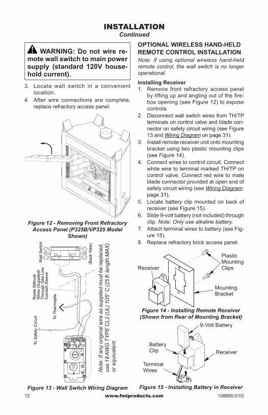
INSTALLATIONWALL SWITCH INSTALLATIONInstallation of a wall switch allows you to activate gas control valve without normal household electricity since the valve operates on millivolt current supplied by heat generated by thermopile. To install wall switch:1. Remove front refractory access panel by
lifting up and angling out firebox opening (see Figure 12, page 12).
2. Using wire and connectors provided, at-tach red wire to terminal marked TH/TP on control valve. Attach white wire to blade connector on open end of safety circuit wiring (see Figure 13, page 12, and Wiring Diagram, page 31).
Note: If any of original wire from unit control must be replaced, use the same type or a higher rated wire (25 ft. maximum length).
www.fmiproducts.com 108660-01G12
INSTALLATIONContinued
Figure 13 - Wall Switch Wiring Diagram
Not
e: If
any
orig
inal
wire
as
supp
lied
mus
t be
repl
aced
, us
e 18
AW
G T
YPE
CL2
(UL)
105
° C (2
5 ft.
leng
th M
AX)
or e
quiv
alen
t.
Con
duit
Sle
eve
To S
afet
y C
ircui
tR
oute
Mill
ivol
t
Thr
ough
Gas
Lin
e
To T
herm
opileW
ires
(Sup
plie
d)W
all S
witc
h
(Bac
k V
iew
)
IN
TH TP THTP
INO
UT
O
FF
PILOT
ON
Figure 12 - Removing Front Refractory Access Panel (P325B/VP325 Model
Shown)
WARNING: Do not wire re-mote wall switch to main power supply (standard 120V house-hold current).
3. Locate wall switch in a convenient location.
4. After wire connections are complete, replace refractory access panel.
OPTIONAL WIRELESS HAND-HELD REMOTE CONTROL INSTALLATIONNote: If using optional wireless hand-held remote control, the wall switch is no longer operational.
Installing Receiver1. Remove front refractory access panel
by lifting up and angling out of the fire-box opening (see Figure 12) to expose controls.
2. Disconnect wall switch wires from TH/TP terminals on control valve and blade con-nector on safety circuit wiring (see Figure 13 and Wiring Diagram on page 31).
3. Install remote receiver unit onto mounting bracket using two plastic mounting clips (see Figure 14).
4. Connect wires to control circuit. Connect white wire to terminal marked TH/TP on control valve. Connect red wire to male blade connector provided at open end of safety circuit wiring (see Wiring Diagram, page 31).
5. Locate battery clip mounted on back of receiver (see Figure 15).
6. Slide 9-volt battery (not included) through clip. Note: Only use alkaline battery.
7. Attach terminal wires to battery (see Fig-ure 15).
8. Replace refractory brick access panel.
Figure 14 - Installing Remote Receiver (Shown from Rear of Mounting Bracket)
Receiver
Mounting Bracket
Plastic Mounting Clips
Figure 15 - Installing Battery in Receiver
Battery Clip
9-Volt Battery
Receiver
Terminal Wires

www.fmiproducts.com108660-01G 13
Installing 9-Volt Battery in Hand-Held Remote Control Unit 1. Remove battery cover on back of remote
control unit.2. Attach terminal wires to battery (not
included). Place battery into battery hous-ing. Note: Only use alkaline battery.
3. Replace battery cover onto remote control unit.
INSTALLATIONContinued
Figure 16 - Installing Battery in Hand-Held Remote Control Unit
GAS LINE HOOK-UP
WARNING: Gas line hookup should be done by your gas supplier or a qualified service person.
WARNING: Before you pro-ceed, make sure your gas supply is OFF.
The appliance and it’s individual shutoff valve must be disconnected from the gas supply piping system during any pressure testing of gas supply piping system at test pressures in excess of 1/2 psig (3.5 kPa). Appliance must be isolated from gas supply piping system by closing its individual manual shutoff valve dur-ing any pressure testing of gas supply piping system at test pressures equal to or less than 1/2 psig (3.5 kPa).A manual shutoff valve has been included in the appliance’s gas supply system. You may consider installing an extra gas shutoff valve outside the appliance’s enclosure (check with local codes) where it can be accessed more conveniently with a key through a wall as shown in Figure 17.
In conformance with local codes, route a 1/2" NPT gas line towards appliance com-ing in from any of the 3 directions shown in Figure 18.
CAUTION: Do not kink flex-ible gas line.
FMI PRODUCTS, LLC recommends that a black iron gas line be routed from the gas source, through a sediment trap (shown in Figure 19), and into appliance. Once con-nected through appliance, a flexible gas line may be used for ease of installation to gas control valve (see Figure 20, page 14).
Figure 17 - Manual Shutoff Valve Installation
Figure 18 - Routing Incoming Gas Line
Typical Exterior Wall Gas Shutoff InstallationKey
Extension
Shutoff Valve
83/8" 105/8"
1/2" NPT IncomingBlack Iron Gas Line
Flexible Gas Line (1 Provided) Can Be Extended OutEither Side
7"
7"
Alternate Gas SupplyThrough Sub-Floor
3" Min.(7.6 cm)
Side Wall
Of Appliance
Incoming 1/2" Gas Line Permitted by Local Codes
Sediment Trap (Not Supplied)
Figure 19 - Sediment Trap
www.fmiproducts.com 108660-01G14
Before connecting the black iron gas line to the inside of the appliance a sediment trap must be included outside the appliance be-tween the gas line and the gas shutoff valve. It must extend down 3" beyond the center of the pipe. Prepare incoming black iron gas line with Teflon tape or pipe joint compound (Check with local building codes).
CAUTION: Compounds used on threaded joints of gas piping shall be resistant to the action of Liquefied Petroleum (LP or propane), and should be applied lightly to ensure excess sealant does not enter the gas line.
WARNING: All gas piping and connections must be tested for leaks after the installation is completed.After ensuring that the gas valve is on, apply a noncorrosive leak detection solution to all con-nections and joints. If bubbles appear, leaks can be detected and corrected.Do not use an open flame for leak testing and do not operate any appliance if a leak is detected.
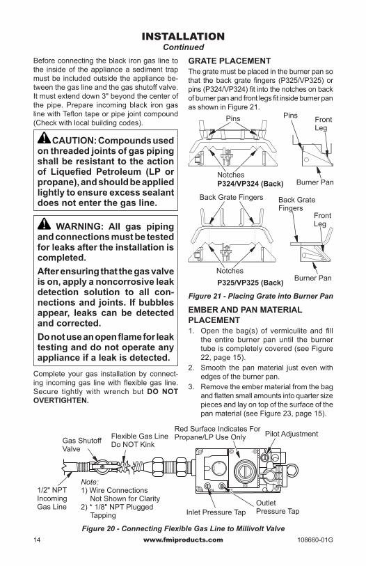
Complete your gas installation by connect-ing incoming gas line with flexible gas line. Secure tightly with wrench but DO NOT OVERTIGHTEN.
INSTALLATIONContinued
GRATE PLACEMENTThe grate must be placed in the burner pan so that the back grate fingers (P325/VP325) or pins (P324/VP324) fit into the notches on back of burner pan and front legs fit inside burner pan as shown in Figure 21.
PIL
OT
ON
OFF
IN OUT
Figure 20 - Connecting Flexible Gas Line to Millivolt Valve
Gas Shutoff Valve
Flexible Gas Line Do NOT Kink
1/2" NPT Incoming Gas Line
Note:1) Wire Connections
Not Shown for Clarity2) * 1/8" NPT Plugged
Tapping
Red Surface Indicates For Propane/LP Use Only Pilot Adjustment
Inlet Pressure TapOutlet Pressure Tap
Figure 21 - Placing Grate into Burner Pan
P324/VP324 (Back)
P325/VP325 (Back)
Pins
Notches
Pins
Back Grate Fingers
Burner Pan
Front Leg
NotchesBurner Pan
Front Leg
Back Grate Fingers
EMBER AND PAN MATERIAL PLACEMENT1. Open the bag(s) of vermiculite and fill
the entire burner pan until the burner tube is completely covered (see Figure 22, page 15).
2. Smooth the pan material just even with edges of the burner pan.
3. Remove the ember material from the bag and flatten small amounts into quarter size pieces and lay on top of the surface of the pan material (see Figure 23, page 15).

www.fmiproducts.com108660-01G 15
4. Place just enough to cover the entire sur-face and leave about a 1/2" gap under the lower grate members to allow air to flow (see Figure 24).
INSTALLATIONContinued
Figure 22 - Fill Entire Burner Pan with Vermiculite (P325/VP325 Models Shown)
Vermiculite (Pan Material)
Burner PanGrate
Figure 23 - Ember Material on Surface of Pan Material (Vermiculite) (P325/VP325
Models Shown)
0.5"
0.5"
Figure 24 - Pan and Ember Material Clearances (P325/VP325 Models Shown)
Ember MaterialBurner Pan
Vermiculite (Pan Material)
Grate
Grate
Burner Pan
Pan and Ember Material
2. Insert pegs on bottom of rear log into holes in rear of grate (see Figure 25).
3. Place top right log into notches on left side of front and rear (see Figure 26).
4. Place top left log into notches on right side of front and rear (see Figure 26).
NOTICE: Do not put lava rock inside the burner pan or around the air mixer fitting. Placing lava rock inside the burner pan or blocking the openings of the pro-pane/LP air-mixer could cause performance problems.
Figure 25 - Installing Front and Rear Logs
Front Log Rear Log
Figure 26 - Installing Top Left and Right Logs
Top Left Log
Top Right Log
LOG PLACEMENT FOR P324/VP324 MODELS1. Place front log onto front of grate sliding
log all the way forward against grate fin-gers (see Figure 25).

www.fmiproducts.com 108660-01G16
LOG PLACEMENT FOR P325(B)/VP325(B) MODELS1. Place rear log onto grate making sure
notches rest over grate (see Figure 27).2. Place front right log onto front right side
of grate with back of log fitting into notch on right front of rear log (see Figure 27).
3. Rest front of front left log between first two grate fingers on left of grate assembly and rear into notch on left front of rear log (see Figure 28).
4. Place top of log 4 into notch on log 1. Rest log 4 on the center of grate as shown in Figure 29.
5. Place top of log 5 into notch on top right of log 1 (see Figure 29). Rest log 5 be-tween two middle grate fingers as shown in Figure 30.
To enhance the look of the hearth you may optionally place the lava rock provided around the front and sides of the burner.
NOTICE: Do not put lava rock inside the burner pan or around the air mixer fitting. Placing lava rock inside the burner pan or blocking the openings of the pro-pane/LP air-mixer could cause performance problems.
INSTALLATIONContinued
Figure 27 - Installing Logs 1 and 2
Rear Log
Front Right Log
Figure 29 - Installing Logs 4 and 5
Figure 30 - Logs Installed
Top Log
Top Y-Log
Rear LogFront Left Log
Figure 28 - Installing Log 3
Front Left Log
Rear Log

www.fmiproducts.com108660-01G 17
COMBUSTION AIR KIT MODEL AK4 (OPTIONAL)The outside air kit may be installed on the left side of the fireplace only. The vent can be installed through the outside wall or a ventilated crawl space. The handle to operate the damper door for the outside air inlet will be located inside the left “screen pocket” of the firebox (see Figure 31). Pull the handle to open or push to close.
CAUTION: Air inlet ducts are not to terminate in attic space.
Figure 31 - Air Kit Handle Location
Air Kit Handle
Screen Pocket
APPLIANCE ENCLOSUREBefore finishing enclosure around appliance, inspect all joints around outer surround. Any gaps between nailing flanges and framing should be sealed with noncombustible insula-tion or caulking (see Figure 32).If appliance is mounted on a raised platform, it must be a continuous surface and not on blocks without a solid surface. This will prevent the entry of cold air by means of conduction through the total bottom of the appliance.
INSTALLATIONContinued
Side Framing
Side Framing
Caulk Here Pack InsulationFigure 32 - Sealing Between Appliance
and Framing
INSTALLING OPTIONAL GLASS DOOR ACCESSORY
CAUTION: Use only glass doors certified for use with this appliance.
Note: Assistance with installation may be needed as glass doors are heavy.These B-vent fireplaces are approved for use with optional bi-fold glass doors (see Acces-sories, page 25). The glass panels may be ordered and installed anytime after the fire-place installation is complete.Follow these steps to install left and right panels:1. With handle at the bottom, completely fold
panel on its hinges.2. With handle facing center of firebox open-
ing, insert lower pivot pin on glass door panel into hole in pivot plate on bottom edge of fireplace opening (see Figure 33).
3. Keeping folded door tilted, slide upper two pins into the guide track found under upper facial edge of firebox opening.
4. Tilt door assembly fully vertical until outer pivot pin snaps into mounting hole in up-per spring clip (see Figure 33).
5. Once top and bottom pins are secured, unfold door into closed position.
6. Repeat process for opposite door as-sembly.
Figure 33 - Installing Optional Glass Door
Spring Clip
Insert Pin Into Spring Clip
Insert Bottom Pivot Pin Into Pivot Plate and Swing Door Into Vertical Position
Pivot Plate
Slide Top Pin Into Door Track

www.fmiproducts.com 108660-01G18
7. To adjust doors, slide them partially open. Using a screwdriver, loosen the hold-down screws in spring clip (see Figure 34) and pivot plate.
8. Close both doors until evenly joined at the middle and note gap at outer edges of face.
9. Reopen one door at a time and retighten upper and lower hold-down screws.
10. Repeat process until both doors are even-ly joined, spaced and working freely.
CAUTION: Glass panels become very hot while the ap-pliance is operating. Do not attempt to adjust or clean glass doors until appliance has fully cooled.
INSTALLATIONContinued
Figure 34 - Adjusting Glass Doors
Spring ClipHold-Down Screw
Side Front Face
Partially Opened Door
Figure 35 - Removing Glass Doors
Spring Clip
Press Spring Clip to Release Pivot Pin
Remove Bottom Pin From Pivot Plate While Sliding Door Out of the Upper Track
Pivot Plate
Fold Bi-Fold Door After Releasing Spring Clip and Slide Door Out of Upper Track
Doors may be removed for replacement or cleaning as follows:1. Partially open door and press up on the
upper spring clip with a screw driver until outer top pivot pin is free of clip.
2. Fully fold frame assembly and slide upper edge toward center of firebox opening until guide pins are free of frame rail (see Figure 35).
CAUTION: Always operate appliance with doors either fully opened or fully closed. Operat-ing appliance with doors par-tially open can result in improper venting of flue products.
www.fmiproducts.com108660-01G 19
OPERATION1. STOP! Read the safety information in
column 1.2. Turn wall switch (if installed) to the OFF
position.3. Turn off all electric power to appliance.4. Fully open glass doors if installed.5. Remove front refractory brick access
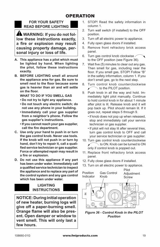
panel.6. Turn gas control knob clockwise
to the OFF position (see Figure 36).7. Wait five (5) minutes to clear out any gas.
Then smell for gas, including near the floor. If you smell gas, STOP! Follow “B” in the safety information, column 1. If you don’t smell gas, go to the next step.
8. Turn control knob counterclockwise to the PILOT position.
9. Push knob in all the way and hold. Im-mediately light pilot manually. Continue to hold control knob in for about 1 minute after pilot is lit. Release knob and it will pop back up. Pilot should remain lit. If it goes out, repeat steps 5 through 9.• If knob does not pop up when released,
stop and immediately call your service technician or gas supplier.
• If pilot will not stay lit after several tries, turn gas control knob to OFF and call your service technician or gas supplier.
10. Turn gas control knob counterclockwise to ON. Knob can be turned to ON
only if control knob is popped out.11. Replace front refractory brick access
panel.12. Fully close glass doors if installed.13. Turn on all electric power to appliance.
Figure 36 - Control Knob in the PILOT Position
PIL
OT
ON
OFF
IN OUT
IN
Position Indicator
Gas Control Knob
Pilot Adjustment Screw
FOR YOUR SAFETY READ BEFORE LIGHTING
WARNING: If you do not fol-low these instructions exactly, a fire or explosion may result causing property damage, per-sonal injury or loss of life.
A. This appliance has a pilot which must be lighted by hand. When lighting the pilot, follow these instructions exactly.
B. BEFORE LIGHTING smell all around the appliance area for gas. Be sure to smell next to the floor because some gas is heavier than air and will settle on the floor.WHAT TO DO IF YOU SMELL GAS• Do not try to light any appliance.• Do not touch any electric switch; do
not use any phone in your building.• Immediately call your gas supplier
from a neighbor’s phone. Follow the gas supplier’s instructions.
• If you cannot reach your gas supplier, call the fire department.
C. Use only your hand to push in or turn the gas control knob. Never use tools. If the knob will not push in or turn by hand, don’t try to repair it, call a quali-fied service technician or gas supplier. Force or attempted repair may result in a fire or explosion.
D. Do not use this appliance if any part has been under water. Immediately call a qualified service technician to inspect the appliance and to replace any part of the control system and any gas control which has been under water.
LIGHTING INSTRUCTIONS
NOTICE: During initial operation of new heater, burning logs will give off a paper-burning smell. Orange flame will also be pres-ent. Open damper or window to vent smell. This will only last a few hours.

www.fmiproducts.com 108660-01G20
TO TURN OFF GAS TO APPLIANCE
1. Turn off wall switch (if installed).2. Turn off all electric power to appliance if
service is to be performed.3. Fully open glass doors if installed.4. Remove front hearth brick and control
access panel.5. Turn gas control knob clockwise
to OFF. Do not force.6. Replace front refractory brick access
panel.7. Fully close glass doors if installed.
OPERATIONContinued
OPTIONAL HAND-HELD REMOTE OPERATION
Note: Receiver and hand-held remote control kit must be purchased separately (see Acces-sories, page 25). Follow installation instruc-tions on page 12 of this manual.
ThermopilePilot Burner
Ignitor
Figure 38 - Correct Pilot Flame Pattern
Figure 37 - Pilot
Thermopile
Pilot Burner
Ignitor
1. After lighting, let pilot flame burn for about one minute. Turn control knob to ON position. Slide the selector switch to the REMOTE position. Note: Burner may light if hand-held remote ON button was on when selector switch was last turned off. You can now turn burner on and off with hand-held remote control unit.
IMPORTANT: Do not leave selector switch in the REMOTE position when pilot is not lit. This will drain battery.
IMPORTANT: Be sure to press ON/OFF buttons on hand-held remote control unit for up to 3 seconds to assure proper operation.
2. Press ON/OFF button to turn the burner on and off. When turning burner off, pilot will remain lit.
IMPORTANT: To turn pilot off, manu-ally turn control knob on heater to OFF position.
3. To leave pilot lit and shut off burners only, turn remote control / wall switch (if installed) to the OFF position.)
TO TURN OFF GAS TO APPLIANCE
1. Press in and turn control knob clockwise to the OFF position.
2. Close equipment shutoff valve
INSPECTING BURNERSCheck pilot flame pattern and burner flame patterns often.
PILOT ASSEMBLYThe pilot assembly is factory preset for the proper flame height. Alterations may have occurred during shipping and handling. The pilot is located on the back right hand side of the burner.The height of thermopile must be 3/8" to 1/2" above pilot flame. Flame from pilot burner must extend beyond thermopile.If your pilot assembly does not meet these requirements:
• Turn adjustment screw marked pilot clockwise to decrease or counterclockwise to increase flame to proper size (see Figure 36, page 19). Do not remove adjustment screw.
• see Troubleshooting, page 22

www.fmiproducts.com108660-01G 21
Figure 39 - Typical Flame Pattern
P325(B) and VP325(B) ModelsP324 and VP324 Models
BURNER FLAME PATTERNBurner flames will be steady; not lifting or float-ing. Flames should go up through the middle of log set. Flames should not "spill" to the edges of the pan or sides of the log set.
INSPECTING BURNERSContinued
CLEANING AND MAINTENANCE
Figure 39 shows a typical flame pattern. If burner flame pattern differs from that de-scribed:• turn appliance off (see To Turn Off Gas to
Appliance, page 20) • see Trouble-shooting, page 22
WARNING: Installation and repair should be done by a quali-fied service person. The appli-ance should be inspected before each use and at least annually by a qualified service person. More frequent cleaning may be required due to excessive lint from carpeting, bedding mate-rial, pet hair, etc. It is imperative that the control compartments, burners, and circulating air sys-tem be kept clean.
WARNING: Logs can be hot. Handle only when cool.
WARNING: Turn off gas and electrical power before servicing appliance.
PILOT AND BURNER• Remove logs and ember material before
cleaning burner and replace when cleaning is complete.
• Burner and controls should be cleaned with compressed air to remove dust, dirt, or lint.
• Use a vacuum cleaner or small, soft bristled brush to remove excess dust, dirt, or lint.
LOGS• If you remove logs for cleaning, refer to
log placement information on page 16 to properly replace logs.
• Use a vacuum cleaner to remove any carbon buildup on logs.
• Replace log(s) if broken. See Replacement Parts, page 25.
• Replace ember material periodically as needed. See Replacement Parts, page 25.

www.fmiproducts.com 108660-01G22
OBSERVED PROBLEMPilot will not light
Pilot will not stay lit
No gas to burner, although wall switch and valve are set to the ON position
Frequent pilot outage
POSSIBLE CAUSE1. No gas supply, or shutoff
valve is OFF2. Air in gas line
3. Construction debris clog-ging pilot orifice
4. Low gas pressure5. Control valve knob is not
on the PILOT position6. Kinked pilot line
7. Bad valve
1. Loose wiring on thermopile to regulator valve. No mil-livolt current is being sent back to regulator
2. If valve knob and wall switch are in the ON posi-tion, probable defective regulator valve
1. Wall switch wires defective or too long
2. Thermopile not generating sufficient voltage
1. Pilot flame may be too low, causing safety pilot to “drop out”
2. Improper venting or exces-sive blockage
REMEDY1. Check to see if you have
gas supply2. Hold regulator control valve
in the PILOT position for 2 to 3 minutes to purge air. If you smell gas stop and wait for a few minutes before trying to light the fireplace
3. Remove debris and dirt, inspect and clean any other possible obstructions
4. Contact your gas supplier5. Refer to section on pilot
lighting6. Have a qualified technician
replace pilot line7. Replace regulator valve (see
Accessories, page 25)
1. Check wiring connections. Refer to wiring diagram shown in Wall Switch Instal-lation, page 10
2. Have a qualified technician replace valve
1. Check electrical connec-tions
2. See Pilot will not stay lit, above
1. Clean and adjust pilot flame for maximum flame im-pingement on thermopile
2. Have the vent system in-spected, including the ter-mination cap. Remove any restriction or obstruction
TROUBLEShOOTINGNote: Before troubleshooting the system, make sure the gas shutoff valve is ON.The two most common causes of a malfunctioning gas appliance are:1. Loose wiring connections2. Construction debris clogging the pilot and/or gas control valve filter

www.fmiproducts.com108660-01G 23
OBSERVED PROBLEMPilot goes out when wall switch is ON
Spark ignitor will not light pilot after repeated triggering of red button
Fireplace produces a clicking/ticking noise just after burner is lit or shut off
POSSIBLE CAUSE1. Millivolt output on thermo-
pile too high
1. Defective ignitor (no spark at electrode)
2. Defective pilot or mis-aligned electrode at pilot (spark at electrode)
3. No gas or low gas pres-sure
4. If using propane/LP gas, no propane/LP gas in tank
1. Metal expanding while heating or contracting while cooling
REMEDY1. Replace thermopile
1. Check for spark at the electrode and pilot; if no spark and electrode wire is properly connected, replace ignitor
2. Using a match, light pilot. If pilot lights, turn off pilot and trigger the red button again. If pilot lights, an improper gas/air mixture caused the improper lighting and a lon-ger purge period is recom-mended. If pilot will not light, check gap at electrode and pilot. Gap should be 1/8" to have a strong spark. If okay, replace pilot
3. A) Check remote shut off valves from fireplace. Valve will be near fireplace or near the main. There can be more than one valve be-tween fireplace and main
B) Low pressure can be caused by bent line, too narrow diameter of pipe, or low line pressure. Check for kinked lines. If none, consult with plumber or gas supplier
4. Check propane/LP supply and contact local propane/LP supplier
1. This is normal with most fireplaces. If noise is ex-cessive, contact qualified service person
TROUBLEShOOTINGContinued

www.fmiproducts.com 108660-01G24
TROUBLEShOOTINGContinued
WARNING: If you smell gas• Shut off gas supply.• Do not try to light any appliance.• Do not touch any electrical switch; do not use any phone in your
building.• Immediately call your gas supplier from a neighbor’s phone. Fol-
low the gas supplier’s instructions.• If you cannot reach your gas supplier, call the fire department.
IMPORTANT: Operating fireplace where impurities in air exist may create odors. Cleaning supplies, paint, paint remover, cigarette smoke, cements and glues, new carpet or textiles, etc., create fumes. These fumes may mix with combustion air and create odors.
POSSIBLE CAUSE1. Fireplace burning vapors
from paint, hair spray, glues, etc. (See IMPOR-TANT statement above)
2. For propane/LP gas, low fuel supply
3. Gas leak. See Warn-ing statement at top of page
1. Gas leak. See Warn-ing statement at top of page
2. Control valve defective
1. Foreign matter between control valve and burner
2. Gas leak. See Warn-ing statement at top of page
1. Improper log placement2. Air holes at burner inlet
blocked
3. Burner flame holes blocked
4. Improper venting or exces-sive blockage
5. Excessive amounts of embers and pan material
OBSERVED PROBLEMFireplace produces unwant-ed odors
Gas odor even when control knob is in OFF position
Gas odor during combus-tion
Dark residue on logs or inside of fireplace
REMEDY1. Ventilate room. Stop using
odor causing products while fireplace is running
2. Contact local propane/LP supplier
3. Locate and correct all leaks (see Gas Line Hook-Up, page 13)
1. Locate and correct all leaks (see Gas Line Hook-Up, page 13)
2. Replace control valve
1. Take apart gas tubing and remove foreign matter
2. Locate and correct all leaks (see Gas Line Hook-Up, page 13)
1. Properly locate logs2. Clean out air holes at burner
inlets. Periodically repeat as needed
3. Remove blockage or replace burner
4. Have the vent system in-spected, including the ter-mination cap. Remove any restrictions or obstruction
5. Clear excess embers until a minimum gap of 1/2" remains under the grate

www.fmiproducts.com108660-01G 25
REPLACEMENT PARTSWhen calling, have ready:• your name• your address• model and serial numbers of your heater• how heater was malfunctioning• purchase dateUsually, we will ask you to return the part to the factory.
Note: Use only original replacement parts. This will protect your warranty coverage for parts replaced under warranty.Contact authorized dealers of this product. If they can’t supply original replacement part(s), call FMI PRODUCTS, LLC at 1-866-328-4537.
SERVICE hINTSWhen Gas Pressure Is Too Low• pilot will not stay lit• burner will have delayed ignition• fireplace will not produce specified heat• propane/LP gas supply may be low if using
propane/LP gasYou may feel your gas pressure is too low. If so, contact your local gas supplier.
TEChNICAL SERVICEYou may have further questions about instal-lation, operation, or troubleshooting. If so, contact FMI PRODUCTS, LLC at 1-866-328-4537. When calling please have your model and serial numbers of your heater ready.You can also visit our web site at www.fmiproducts.com.
ACCESSORIESPurchase these accessories from your local dealer. If they can not supply these accessories call FMI PRODUCTS, LLC at 1-866-672-6040 for information. You can also write to the ad-dress listed on the back page of this manual.AIR KIT - AK4Optional kit helps offset the negative pressure of-ten existing in today's tightly constructed homes.REMOTE CONTROL KITSMLCR - Hand-Held ON/OFF RemoteGWMS2 - Wall Mount ON/OFF Switch32" ExTRUDED ALUMINUM BI-FOLD GLASS DOORSBD32 - Black FinishBD32B - Brushed Brass FinishBD32P - Platinum Finish32" FIxED GLASS DOOR KITFD32 - Black FinishFD32B - Brushed Brass FinishFD32P - Platinum FinishBRICK LINER - BL3232" Refractory Standard Brick Liner Kit
BLOWER KIT-BKSquirrel Cage Blower With Speed ControlPERIMETER TRIMPT32 - BlackPT32B - Brushed BrassPT32P - PlatinumLOUVER TRIM KIT (Rolled Only)LT32B - Brushed BrassLT32P - PlatinumFACE/LOUVER PANEL KITSSP32 - Smooth Faced - BlackSL32 - Stamped Louver - BlackRL32 - Rolled Louver- BlackFP32 - Filigree Panel - BlackFP32B - Filigree Panel - Brushed BrassFP32P - Filigree Panel - PlatinumFIRE CRACKLE - CF6-A1 Creates the sound of a real burning fire.PROPANE/LP GAS CONVERSION KITPCDM-324 - Propane/LP Gas, Millivolt Mod-els for use with (V)P324 SeriesPCDM-325 - Propane/LP Gas, Millivolt Mod-els for use with (V)P325 Series

www.fmiproducts.com 108660-01G26
PARTSMODELS P324 AND VP324
3343 41
15
19
6
7
24
14
30
2629
2528
27
36
14
12
1323
1631
32
5
5
20
32
38
39
40
4
34
35
2117
8
10
18
44
2
22
1
3
44
3742
11
11
9

www.fmiproducts.com108660-01G 27
PARTSMODELS P324 AND VP324This list contains replaceable parts used in your heater. When ordering parts, follow the instructions listed under Replacement Parts on page 25 of this manual.
**Not a field replaceable part.
KEY NO. PART NO. DESCRIPTION QTY.1 ** Insulation Pan 12 108403-02 Fireplace Top Assembly 13 ** Fireplace Surround 14 108425-01 Air Rod Retainer 15 108423-01 Panel Closure 26 ** Firebox Bottom 17 108410-01 Firebox Surround 18 108411-01 Air Separator 19 106827-01 4" Gasket 110 108416-01 4" Collar 111 108769-03 Extension Deflector 112 108428-03 Bottom Front Refractory, Std. Brick 113 108426-03 Bottom Rear Refractory, Std. Brick 114 106683-01 Firebox Support Leg 215 24353 Box Assembly 116 108701-01 Screen Rod 217 ** Firebox Top Assembly 118 108415-01 Starter Pipe Collar 119 106703-02 Damper Door Assembly 120 ** Firebox Face 121 108412-01 Smoke Deflector 122 ** Fireplace Top Insulation 123 109797-01 Grate Assembly 124 109107-01 Burner Assembly (see page 30) 125 14512 Gas Control Valve (Natural Gas) 1 14513 Gas Control Valve (Propane/LP) 1 26 107741-02 Valve Bracket 127 14261 Piezo Ignitor 128 108368-01 3/8" Flex Line 129 11107 Screw, #10-32 x 1/4 PPH 430 108005-04 Wire Harness 131 11418 Push-On Nut 232 108440-01 Screen 233 14123 Strain Relief 134 14574 Limit Switch 135 22912 Draft Divertor 136 14253 Flexible Supply Line w/ Shutoff Valve 137 20042 Air Kit Cover 138 20088 Door Stop 139 20089 Pivot Clip 240 20090 Spring Clip 241 21171 Gas Knockout Cover 442 108652-01 Gas Conduit Assembly, Left 143 108654-01 Gas Conduit Assembly, Right 144 20280 Top Spacer 4
PARTS AVAILABLE NOT SHOWN901155-01 Vermiculite Bag 1901156-01 Pan Material 1901157-01 Lava Rock 1

www.fmiproducts.com 108660-01G28
PARTSP325(B) AND VP325(B) MODELS
33 4341
15
19
6
7
24
14
30
2629
2528
27
18
14
12
13
23
10
36
9
3635
1631
32
5
5
20
32
38
39
40
4
34
21
17
846
45
44
2
22
1
3
44
11
3742
47
47

www.fmiproducts.com108660-01G 29
KEYNO. PART NO. DESCRIPTION QTY.1 ** Insulation Pan 12 108403-01 Fireplace Top Assembly 13 ** Fireplace Surround 14 108425-01 Air Rod Retainer 15 108423-01 Panel Closure 26 108409-01 Firebox Bottom 17 ** Firebox Surround 18 108411-01 Air Separator 19 108434-01 Left Refractory, Std. Brick (B Models) 110 108432-01 Right Refractory, Std. Brick (B Models) 111 108430-01 Rear Refractory, Std. Brick (B Models) 112 108428-01 Bottom Front Refractory, Std. Brick 113 108426-01 Bottom Rear Refractory, Std. Brick 114 106683-01 Firebox Support Leg 215 24353 Box Assembly 116 108701-01 Screen Rod 217 ** Firebox Top Assembly 118 14253 Flexible Supply Line w/ Shutoff Valve 119 106703-02 Damper Door Assembly 120 ** Firebox Face 121 108412-01 Smoke Deflector 122 ** Fireplace Top Insulation 123 109040-01 Grate Assembly 124 108712-03 Burner Assembly (see page 30) 125 14512 Gas Control Valve (Natural Gas) 1 14513 Gas Control Valve (Propane/LP) 126 107741-02 Valve Bracket 127 14261 Piezo Ignitor 128 108368-01 3/8" Flex Line 129 11107 Screw, #10-32 x 1/4 PPH 430 108005-04 Wire Harness 131 11418 Push-On Nut 232 108440-01 Screen 233 14123 Strain Relief 134 14574 Limit Switch 135 22912 Draft Diverter 136 22084 Brick Liner Retainer 237 20042 Air Kit Cover 138 20088 Door Stop 139 20089 Pivot Clip 240 20090 Spring Clip 241 21171 Gas Knockout Cover 442 108652-01 Gas Conduit Assembly, Left 143 108654-01 Gas Conduit Assembly, Right 144 20280 Top Spacer 445 108415-01 Starter Pipe Collar 146 108417-01 5" Collar 147 108769-03 Extension Deflector 2
PARTS AVAILABLE NOT SHOWN901155-01 Vermiculite Bag 1901156-01 Pan Material 1901157-01 Lava Rock 1
PARTSP325(B) AND VP325(B) MODELSThis list contains replaceable parts used in your heater. When ordering parts, follow the instructions listed under Replacement Parts on page 25 of this manual.
**Not a field replaceable part.

www.fmiproducts.com 108660-01G30
3
13
13
9NG
LP
8
8
4
9
12
10
11
6 2
5
1
7
KEY NO. PART NO. DESCRIPTION QTY.1 107742-03 Burner Pan 12 109794-01 Burner Tube 13 107748-01 Burner Bracket 14 107985-01 Pilot Shield 15 109793-01 Divider Pan 16 11209 Nut, #10-24 17 11147 Screw, #10-24x1/2 18 901066-01 Brass Air Mixer
(Natural Gas)1
901066-02 Brass Air Mixer (Propane/LP)
1
9 901064-12 Injector (NG) 1901065-11 Injector (LP) 1
10 108084-01 Pilot (NG) 111 108085-02 Pilot Orifice (LP) 112 11102 Screw, #8-32x3/8 213 11165 Screw, #10x5/8 Mod.
Tr. Blk. Ox2
PARTSBURNER ASSEMBLYThis list contains replaceable parts used in your heater. When ordering parts, follow the instructions listed under Replacement Parts on page 25 of this manual.
KEYNO. PART NO. DESCRIPTION QTY.1 107742-03 Burner Pan 12 109037-01 Burner Tube 13 107748-01 Burner Bracket 14 107985-01 Pilot Shield 15 901681-01 Burner Clamp 16 11209 Nut, #10-24 17 11147 Screw, #10-24x1/2 18 901066-01 Brass Air Mixer (NG) 1
901066-02 Brass Air Mixer (LP) 19 901064-11 Injector (NG) 1
901065-09 Injector (LP) 110 108084-01 Pilot (NG) 111 108085-02 Pilot Orifice (LP) 112 11102 Screw, #8-32x3/8 213 11165 Screw, #10x5/8 Mod.
Tr. Blk. Ox2
3
1313
9
NG
LP
8
8
4
9
12
10
11
6
2
5
1
7
P324 and VP324 Models P325(B) and VP325(B) Models
www.fmiproducts.com108660-01G 31
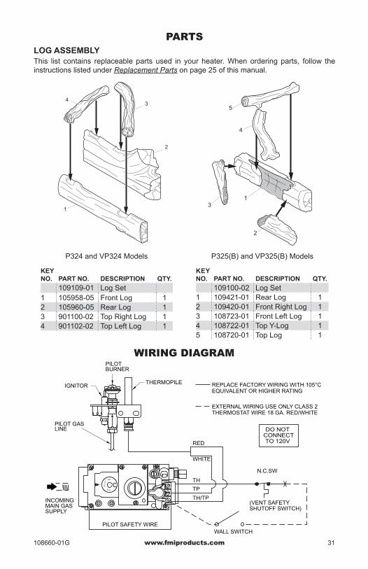
PARTSLOG ASSEMBLYThis list contains replaceable parts used in your heater. When ordering parts, follow the instructions listed under Replacement Parts on page 25 of this manual.
KEY NO. PART NO. DESCRIPTION QTY.
109109-01 Log Set1 105958-05 Front Log 12 105960-05 Rear Log 13 901100-02 Top Right Log 14 901102-02 Top Left Log 1
P324 and VP324 Models P325(B) and VP325(B) Models
1
4
2
3
1
2
3
4
5
KEY NO. PART NO. DESCRIPTION QTY. 109100-02 Log Set1 109421-01 Rear Log 12 109420-01 Front Right Log 13 108723-01 Front Left Log 14 108722-01 Top Y-Log 15 108720-01 Top Log 1
WIRING DIAGRAM
DO NOTCONNECT
RED
REPLACE FACTORY WIRING WITH 105°CEQUIVALENT OR HIGHER RATING
THERMOSTAT WIRE 18 GA. RED/WHITEEXTERNAL WIRING USE ONLY CLASS 2
N.C.SW
(VENT SAFETYSHUTOFF SWITCH)
WHITE
TH/TP
TP
TH
WALL SWITCH
TO 120V
THERMOPILE
PILOTBURNER
IGNITOR
LINEPILOT GAS
O
FF
PIL
OT
ON
PILOT SAFETY WIRE
MAIN GASINCOMING
SUPPLY

108660-01Rev. G09/09
WARRANTykEEP ThIS WARRANTy
FMI PRODUCTS, LLC LIMITED WARRANTIESNew Products
Standard Warranty: FMI PRODUCTS, LLC warrants this new product and any parts thereof to be free from defects in material and workmanship for a period of four (4) year from the date of first purchase from an authorized dealer provided the product has been installed, maintained and operated in accordance with FMI PRODUCTS, LLC’s warnings and instructions.For products purchased for commercial, industrial or rental usage, this warranty is limited to 90 days from the date of first purchase.
Factory Reconditioned ProductsLimited Warranty: FMI PRODUCTS, LLC warrants factory reconditioned products and any parts thereof to be free from defects in material and workmanship for 30 days from the date of first purchase from an authorized dealer provided the product has been installed, maintained and operated in accordance with FMI PRODUCTS, LLC’s warnings and instructions.
Terms Common to All WarrantiesThe following terms apply to all of the above warranties:Always specify model number and serial number when contacting the manufacturer. To make a claim under this warranty the bill of sale or other proof of purchase must be presented.This warranty is extended only to the original retail purchaser when purchased from an authorized dealer, and only when installed by a qualified installer in accordance with all local codes and instructions furnished with this product.This warranty covers the cost of part(s) required to restore this product to proper operating condition and an allowance for labor when provided by a FMI PRODUCTS, LLC Authorized Service Center or a provider approved by FMI PRODUCTS, LLC. Warranty parts must be obtained through authorized dealers of this product and/or FMI PRODUCTS, LLC who will provide original factory replacement parts. Failure to use original factory replacement parts voids this warranty.Travel, handling, transportation, diagnostic, material, labor and incidental costs associated with warranty repairs, unless expressly covered by this warranty, are not reimbursable under this warranty and are the responsibility of the owner.Excluded from this warranty are products or parts that fail or become damaged due to misuse, accidents, improper installation, lack of proper maintenance, tampering, or alteration(s).This is FMI PRODUCTS, LLC’s exclusive warranty, and to the full extent allowed by law; this express war-ranty excludes any and all other warranties, express or implied, written or verbal and limits the duration of any and all implied warranties, including warranties of merchantability and fitness for a particular purpose to four (4) year on new products and 30 days on factory reconditioned products from the date of first purchase. FMI PRODUCTS, LLC makes no other warranties regarding this product.FMI PRODUCTS, LLC’s liability is limited to the purchase price of the product, and FMI PRODUCTS, LLC shall not be liable for any other damages whatsoever under any circumstances including indirect, incidental, or consequential damages.Some states do not allow limitations on how long an implied warranty lasts or the exclusion or limitation of incidental or consequential damages, so the above limitation or exclusion may not apply to you. This warranty gives you specific legal rights, and you may also have other rights which vary from state to state. For information about this warranty contact:
Model (located on product or identification tag) _____________________________
Serial No. (located on product or identification tag) __________________________
Date Purchased __________________________
Keep receipt for warranty verification.
2701 S. Harbor Blvd.Santa Ana, CA 92704
1-866-328-4537www.fmiproducts.com