Embed Size (px)
Citation preview

ELAN Home Systems ● 1690 Corporate Circle ● Petaluma, CA 94954 USA tech support: 800.622.3526 • main: 760.710.0990 • sales: 877.289.3526 • email: [email protected]
©2013 ELAN Home Systems. All rights reserved. ELAN and g! are trademarks of ELAN Home Systems. All other trademarks are the property of their respective owners.
Integration Note
Manufacturer: Pentair Water
Model Number(s): IntelliTouch, EasyTouch
Minimum Core Module Version:
Document Revision Date: 09/25/2017
OVERVIEW AND SUPPORTED FEATURES
Installing a Pentair EasyTouch/Intellitouch system can be broken down into the following steps:
1. Work with the client and the pool builder to ensure cabling from the EasyTouch/Intellitouch load center
is pulled to a location suitable for the Pentair HW-EBP-100 ScreenLogic2 Protocol Adapter, or HC
Controller RS-485 Port to communicate with the g! system.
2. Ensure that the pool builder properly programs the EasyTouch/Intellitouch system. See Programming
EasyTouch/Intellitouch for more details.
3. Install and connect the Pentair HW-EBP-100 ScreenLogic2 Protocol Adapter, or HC Controller
RS-485 Port electrically to the EasyTouch/Intellitouch controller. See Installation Overview for the list of steps required.
4. Integrate the pool / spa system into the g! system and test proper operation. This step is outlined in
g! Configuration Details.
THE LOAD CENTER
Pentair uses the term Load Center and Power Center to describe the sheet metal enclosure typically mounted at the equipment pad that includes the high voltage relays that control the pool equipment (lights,
pumps, etc.). The Load Center includes the EasyTouch/Intellitouch Controller, which is the brains for the system, and is mounted above the high voltage relays in a low voltage section of the panel.
In this document we only use the term Load Center to describe the panel, including the controller.
EASYTOUCH/INTELLITOUCH SUPPORTS THE FOLLOWING FEATURES
Manual Control: EasyTouch/Intellitouch systems can be easily controlled from the Indoor Control Panel. Individual circuits can be turned on or off directly at the Load Center itself.
Devices Supported: The EasyTouch/Intellitouch line supports a wide variety of pool installations.
Anywhere from 5 to 50 circuits are supported. Refer to the table in Suggested Design Procedure for details of the EasyTouch/Intellitouch models: refer to the Pentair Water Web site for more details (www.pentairpool.com).
THE FOLLOWING FEATURES ARE NOT SUPPORTED IN g!
Multiple Pentair Controllers: g! will only integrate with one Pentair Controller in a system.
Elan HW-EB-100 Serial Bricks: The Elan HW-EB-100 Serial Bricks is not compatible with Pentair pool systems
Any feature not specifically noted as “supported” is not supported.

2 of 13
IMPORTANT NOTE ON EASYTOUCH/INTELLITOUCH PROGRAMMING
The EasyTouch/Intellitouch system must be programmed to operate properly with the g! system. This process sets the type of device (cleaner, light, etc) for each circuit, in addition to other important settings, including the circuit name, and if the circuit should be turned on in cold weather to prevent the pipes from freezing. Initial programming can be done with an Indoor Control Panel or a Service Man’s Panel, both of
which are familiar to the pool contractor. Initial programming can also be done from the g! Configurator, as
explained in Programming EasyTouch/Intellitouch below.
IMPORTANT NOTE ON PENTAIR HW-EBP-100 SCREENLOGIC2 PROTOCOL ADAPTER
The Pentair HW-EBP-100 Must be updated to Firmware revision 999 in order to be recognized by Elan systems.
This Firmware can be downloaded from the Software applications section of the dealer downloads page: http://www.elanhomesystems.com/support-downloads
Or it can be direct-accessed at: http://www.elanhomesystems.com/support-downloads
Instructions for integration:
1. Install and fully program the Pentair pool system for standalone control as normal. 2. Install the Pentair ScreenLogic2 Protocol Adapter following standard wiring guidelines. 3. *Launch g! Configurator and attempt to create a new communication device “IP to Serial:
SerialBrick”. Note that by default the name should be “Pentair: xx-xx-xx” where the last 6 digits of the unit MAC address make up the x’s.
If the desired unit appears in the “EdgeBrick” drop down, no update is needed.
If the desired unit does not appear, continue. 4. Launch ScreenLogic Connect and see if the system appears in Local Systems. Note: if you don’t
have ScreenLogic Connect installed, it is available on the Pentair website.
If the unit does not appear, troubleshoot connections and network should be performed until the system can be detected in either g! or ScreenLogic Connect.
5. If the unit is visible in ScreenLogic Connect but not visible to g! systems on the same network, perform the 999 update.
* Optionally instead of ScreenLogic Connect, a special version of HLDEVICE was created that will check for Pentair devices on the new network port. You could run HLDEVICE and PENTAIRHLDEVICE side by side to determine visibility and version.
Pentair Update 999 Notes:
Pentair Update 999 is modified version of the Pentair 5.2.730 firmware with the network ports reverted to those compatible with g! systems.
Version 5.2.999 was chosen as the number to make the firmware version easy to distinguish from other firmware versions.
Though two revisions of the Pentair HWEBP100 exist, they are based on the similar hardware and use a single firmware version.
There is no reason to update older revisions of firmware to this model for g! integration.
After installation of update 999 the Pentair brick may not be used for standalone ScreenLogic local/remote connections.

3 of 13
If desired, the unit may be reverted to standalone Pentair software by using the latest update available on the Pentair website. See the Protocol Adapter Update tool download.
Prior to running the 999 update it is strongly recommended to use ScreenLogic Connect’s Configure IP Info or Pentair-HLDEVICE’s Basic Config to assign a static IP address to the unit.
I have tested the update on two older HomeLogic manufactured units: 1 HWEBP100 and 1 HWEB102. Both were updated to 725 and 730 and then flashed to 999 with success. We do not have new hardware available for comparison, though our understanding is the hardware is similar and should offer the same experience.
Pentair Update 999 Instructions: Note: it is strongly recommended to assign a static IP address on the HWEBP100 prior to attempting to flash the firmware—the HWEBP100 will reboot during the process and a changed IP address will cause the update to fail. As with all updates, a hardwired local network connection should be used to perform the update.
1. Launch the updater program pentairupdate999.exe. 2. Select the Pentair Protocol Adapter from the list and click Start. Note that g! systems may
appear but should not allow install if selected.
3. The updater will connect and reflash the firmware automatically:

4 of 13
Note: “Retry Block” messages are OK provided the update continues and completes successfully.
4. Wait until the updater reports the success and click OK to exit the updater.

5 of 13
5. Click cancel to close out of the ScreenLogic Update utility when finished.
6. Following completion of the updater the unit should be available for addition to the g!
Configurator as a “IP to Serial SerialBrick” Communication Device.

6 of 13
EXAMPLE OF POOL AND SPA SYSTEM
The following diagram shows one possible pool and spa configuration:
Jet Pump
Blower
Filter Pump
Skimmer
Solar Booster
Electric
Heater
Solar
Heat
Main
Drain
Filter
Cleaner Pump
Cleaner
Spa Light
SAL
Pool Light1
SAm
Spa
Pool
Pool Light2
SAm
Water
Sensor
Solar
Sensor
Air
Sensor
Solar
Valve
Intake
Valve
Return
Valve
The pumps, boosters and the lights are each high voltage Circuits in IntelliTouch, and wire to relays in the Load Center. The intake and return valves are driven by low voltage actuators that connect to the Load Center. The water and temperature sensors are simple thermistor devices that also wire to the Load Center.
The diagram above includes both a pool and a spa, setup as a shared system. In other words, there is a
single pump / filter / heater that is connected to both the pool and the spa, through the Intake Valve and
the Return Valve. Depending on the valve positions, the following are done:
1. The water is circulated in the pool only, and the water in the spa is unaffected.
2. The water is circulated in the spa only, and the water in the pool is unaffected.
3. The water is circulated from the pool and pumped into the spa. The water then overflows the spa
and returns to the pool, through a Spillway.
4. The water is circulated from the spa to the pool. Since the spa is typically much smaller than the pool, this will drain the spa.
IntelliTouch is designed to handle a wide variety of pool and spa configurations, including a stand-alone pool or spa as well as a pool and spa setup each with their own filter pump and heater.

7 of 13
SUGGESTED DESIGN PROCEDURE
STEP 1: DETERMINE THE APPROPRIATE PENTAIR CONTROLLER
Model Circuits Comments
EasyTouch 4/4P/8/8P 4/8
i5 5 Shared system: pool and spa share one pump / heater
i5S 5 Single body of water
i7+3 7 Shared system: pool and spa share one pump / heater
i9+3 9 Shared system: pool and spa share one pump / heater
i9+3S 9 Single body of water
i10+3D 10 Dual body of water: two pumps, two heaters
i5X 5 Expansion: 5 additional circuits
i10X 10 Expansion: 10 additional circuits
The pool contractor will typically work with the client to determine how many circuits are needed, and how to setup the IntelliTouch system.
During this planning process, work with the client and the pool contractor to assist in the selection of a
controller that will satisfy their requirements and also tie into the g! system. Refer to the table above and the details available on the Pentair Web site.
PROGRAMMING INTELLITOUCH
There are two methods to program the IntelliTouch system.
The first method uses an IntelliTouch Indoor Control Panel or an IntelliTouch Service Man’s Panel, and is
the method a pool installer would use if no g! system were present.
The second method relies instead on the g! Configurator, and allows a system to be programmed with the
IntelliTouch ScreenLogic user interface. This approach is recommended where there is no Indoor
Control Panel or Service Man’s Panel. Refer to the IntelliTouch ScreenLogic documentation
available on Pentair’s Web site for details on the ScreenLogic user interface.
For more details on programming Pentair IntelliTouch (ScreenLogic), see Pentair’s website:
http://www.pentairpool.com/pool-pro/manuals/section.php?s=5

8 of 13
INSTALLATION OVERVIEW
The following steps are needed for installation.
Refer to the diagrams that follow for various wiring scenarios.
1. If using a Pentair HW-EBP-100 ScreenLogic2 Protocol Adapter, decide where the Pentair HW-
EBP-100 ScreenLogic2 Protocol Adapter will be installed. Two common choices are at a location
near an Indoor Control Panel, and inside the g! System Enclosure. Due to heat inside the Load
Center, DO NOT install the Pentair HW-EBP-100 ScreenLogic2 Protocol Adapter inside the load center.
2. During the rough-in phase, run a cable from the Load Center location to the Pentair HW-EBP-100
ScreenLogic2 Protocol Adapter location. This cable is typically the same as the 18X4 control wiring
typically used to connect the Load Center to an IntelliTouch Indoor Control Panel. If using an HC
Controller, you may wish to run Cat5 instead.
3. If the Pentair HW-EBP-100 ScreenLogic2 Protocol Adapter will not be installed inside the g!
System Enclosure, then run a Cat5 cable from the System Enclosure to the HW-EBP-100 location.
You may also wish to install a single-gang outlet adjacent to the HW-EBP-100 to cleanly terminate the Cat5 to an RJ45 Female connector.
4. Install the IntelliTouch equipment and test that all circuits operate normally in manual mode.
5. Install the Pentair HW-EBP-100 ScreenLogic2 Protocol Adapter.
6. Electrically connect the Pentair HW-EBP-100 ScreenLogic2 Protocol Adapter to IntelliTouch and to the Ethernet network.
7. Check function from the Viewer and Configure Circuits from Configurator if necessary.

9 of 13
CONNECTION DIAGRAM – HW-EBP-100:
The diagram below shows the connections that correspond to the example pool provided above. Refer to
the Bill of Materials for additional detail, including specific part numbers.
Load Centeror
Power Center
Cable provided with
Network Assy.
Cat5 Cable Assy.
3
RS-485 ETHERNET
2
5Network
Assembly/Switch
6
4
Any Ethernet LAN Port
g! System Controller
18AWG Control Wire
1 Load Center
Valve Controls
Intake Valve
Return Valve
Valve A
Valve B
Special Purpose Relays
Electric Heater
Solar
2 Speed
COM Ports
First COM Port
Second COM Port
Intake Valve
Return Valve
Solar Valve
Electric Heater
Solar Booster
Temperature Sensors
Filter Pump
Aux 1
Aux 2
Aux 3
Aux 4
Aux 5
Aux 6
Aux 7
Aux 8
Air Sensor
Standard Circuits
Solar Sensor
Water Sensor
Filter Pump
Spa Light SAL
Pool Light1: SAm
Pool Light2: Sam
Cleaner Pump
Blower
Jet Pump
Air Sensor
Solar Sensor
Water Sensor
Pentair HW-EBP-100 ScreenLogic2 Protocol Adapter
BILL OF MATERIALS
# D evice M anufacturer P art N umber P ro to co l C o nnecto r T ype N o tes
1 Load Center Pentair Various RS-485 and Power Terminal Strip Use either COM Port
2 18AWG Control Wire Various N/A RS-485 and Power Terminal Strip
3 Pentair HW-EBP-100 ScreenLogic2 Protocol AdapterHomeLogic HW-EBP-100 RS-485 X IP Terminal Strip X RJ-45 Female
4 Cat5 Cable Assy. Installer N/A IP RJ-45 M ale X RJ-45 M ale
5 Network Assembly ELAN NWA18 IP X IP RJ-45 Female X RJ-45 Female Use any available LAN port
6 g! System Controller ELAN Various (e.g. HC12) IP RJ-45 Female
WIRING DIAGRAM:
The diagram below shows the connection from the controller in the Load Center to the Pentair HW-EBP-
100 ScreenLogic2 Protocol Adapter:
RED
YEL
BLK
GR
N
Control Board(i5, i9+3, etc.)
4 3 2 1
+DT+15 -DT GND
RED
YEL
BLK
GR
N
4 3 2 1
+DT+15 -DT GND COM PORTSUSE EITHER
OR BOTH
To other devices: wireless transceivers, Indoor Control
Panels, etc.
Pentair HW-EBP-100 ScreenLogic2
Protocol Adapter

10 of 13
CONNECTION DIAGRAM - HC CONTROLLER:
The diagram below shows the connections that correspond to the example pool provided above. Refer to
the Bill of Materials for additional detail, including specific part numbers.
Load Center
or
Power Center
2
3HC
Controller
1 Load Center
Valve Controls
Intake Valve
Return Valve
Valve A
Valve B
Special Purpose Relays
Electric Heater
Solar
2 Speed
COM Ports
First COM Port
Second COM Port
Intake Valve
Return Valve
Solar Valve
Electric Heater
Solar Booster
Temperature Sensors
Filter Pump
Aux 1
Aux 2
Aux 3
Aux 4
Aux 5
Aux 6
Aux 7
Aux 8
Air Sensor
Standard Circuits
Solar Sensor
Water Sensor
Filter Pump
Spa Light SAL
Pool Light1: SAm
Pool Light2: Sam
Cleaner Pump
Blower
Jet Pump
Air Sensor
Solar Sensor
Water Sensor
Cat 5
RS485 Port
BILL OF MATERIALS
# D evice M anufacturer P art N umber P ro to co l C o nnecto r T ype
1 Load Center Pentair Various RS-485 Terminal Strip
2 Cat5 Cable Assy. Installer N/A RS-485 Terminal Strip X RJ-45 Female
3 HC Controller ELAN Various (e.g. HC12) RS-485 RJ-45 Female

11 of 13
WIRING DIAGRAM – HC CONTROLLER:
The diagram below shows the connection from the controller in the Load Center to the SerialBrick – Pool and Spa:
RE
D
YE
L
BL
K
GR
N
Control Board
(i5, i9+3, etc.)
4 3 2 1
+DT+15 -DT GND
RE
D
YE
L
BL
K
GR
N
4 3 2 1
+DT+15 -DT GND COM PORTSUSE EITHER
OR BOTH
To other devices: wireless
transceivers, Indoor
Control Panels, etc. 6: Green7: White / Brown8: Brown
5: White / Blue
2: Orange3: White / Green4: Blue
1: White / Orange
RJ45(Clip Down)
8
1
(568B Colors)TO RS485 Port on HC
Pentair Com
Port
RJ45
PIN
568B Colors 568A Colors
Yellow (+DT) 3 White/Green White/Orange
Green (-DT) 6 Green Orange
Black (GROUND) 7 White/Brown White/Brown
Red (V+) N/C NOT CONNECTED NOT CONNECTED
Table: Wiring Detail from Pentair Com Port connection to RJ45 – RS485 Com Port on HC Controller.
Important: Do not connect the RED connection from Pentair to a HC RS485 port.
12 of 13
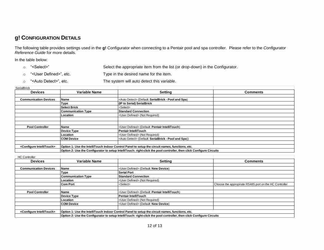
g! CONFIGURATION DETAILS
The following table provides settings used in the g! Configurator when connecting to a Pentair pool and spa controller. Please refer to the Configurator Reference Guide for more details.
In the table below:
o “<Select>” Select the appropriate item from the list (or drop-down) in the Configurator.
o “<User Defined>”, etc. Type in the desired name for the item.
o “<Auto Detect>”, etc. The system will auto detect this variable.
SerialBrick
Devices Variable Name Setting Comments
Communication Devices Name <Auto Detect> (Default: SerialBrick - Pool and Spa)
Type (IP to Serial) SerialBrick
Select Brick <Select>
Communication Type Standard Connection
Location <User Defined> (Not Required)
Pool Controller Name <User Defined> (Default: Pentair IntelliTouch)
Device Type Pentair IntelliTouch
Location <User Defined> (Not Required)
COM Device <Auto Detect> (Default: SerialBrick - Pool and Spa))
<Configure IntelliTouch> Option 1: Use the IntelliTouch Indoor Control Panel to setup the circuit names, functions, etc.
Option 2: Use the Configurator to setup IntelliTouch: right-click the pool controller, then click Configure Circuits
HC Controller
Devices Variable Name Setting Comments
Communication Devices Name <User Defined> (Default: New Device)
Type Serial Port
Communication Type Standard Connection
Location <User Defined> (Not Required)
Com Port <Select> Choose the appropirate RS485 port on the HC Controller
Pool Controller Name <User Defined> (Default: Pentair IntelliTouch)
Device Type Pentair IntelliTouch
Location <User Defined> (Not Required)
COM Device <User Defined> (Default: New Device)
<Configure IntelliTouch> Option 1: Use the IntelliTouch Indoor Control Panel to setup the circuit names, functions, etc.
Option 2: Use the Configurator to setup IntelliTouch: right-click the pool controller, then click Configure Circuits

13 of 13
COMMON MISTAKES
1. Failing to test the Cat5 cable assembly. It is easy to make a mistake when terminating the Cat5 cable with the RJ-45 connectors. Always use a LAN tester to check for continuity and shorts.
2. Failing to program the IntelliTouch prior to integration with g!. The IntelliTouch system must be fully
programmed and tested before the g! system will be able to properly read the settings.
3. Using an Elan HW-EB-100 Serial Brick. The Elan HW-EB-100 Serial Bricks is not compatible with
Pentair pool systems. Use the Pentair HW-EBP-100 ScreenLogic2 Protocol Adapter.
4. Improper programming of the IntelliTouch system. Any mistakes made on the programming may
cause erratic or undesirable behavior in the g! interface and control. For example programming a system with more than one Primary Pool or more that one Primary Spa circuits as shown below:
Example of incorrect programming:
Example of correct programming: