Embed Size (px)
Citation preview

Tran
slat
ion
of t
he o
rigin
al in
stru
ctio
nsP
T 02
08 B
EN
/D (1
008)
HiPace 80Turbopump
Operating Instructions
EN
Table of contents
Table of contents
1 About this manual. . . . . . . . . . . . . . . . . . . . . . . . . . . . . . . . . . . . . . . . . . . . . . . 3
1.1 Validity. . . . . . . . . . . . . . . . . . . . . . . . . . . . . . . . . . . . . . . . . . . . . . . . . . . . . 31.2 Conventions . . . . . . . . . . . . . . . . . . . . . . . . . . . . . . . . . . . . . . . . . . . . . . . . 3
2 Safety . . . . . . . . . . . . . . . . . . . . . . . . . . . . . . . . . . . . . . . . . . . . . . . . . . . . . . . . . 5
2.1 Safety precautions . . . . . . . . . . . . . . . . . . . . . . . . . . . . . . . . . . . . . . . . . . . 52.2 Protective equipment . . . . . . . . . . . . . . . . . . . . . . . . . . . . . . . . . . . . . . . . . 62.3 Proper use. . . . . . . . . . . . . . . . . . . . . . . . . . . . . . . . . . . . . . . . . . . . . . . . . . 62.4 Improper use. . . . . . . . . . . . . . . . . . . . . . . . . . . . . . . . . . . . . . . . . . . . . . . . 7
3 Transport and storage . . . . . . . . . . . . . . . . . . . . . . . . . . . . . . . . . . . . . . . . . . . . 8
3.1 Transport . . . . . . . . . . . . . . . . . . . . . . . . . . . . . . . . . . . . . . . . . . . . . . . . . . . 83.2 Storage . . . . . . . . . . . . . . . . . . . . . . . . . . . . . . . . . . . . . . . . . . . . . . . . . . . . 8
4 Product description . . . . . . . . . . . . . . . . . . . . . . . . . . . . . . . . . . . . . . . . . . . . . . 9
4.1 Product identification . . . . . . . . . . . . . . . . . . . . . . . . . . . . . . . . . . . . . . . . . 94.2 Function . . . . . . . . . . . . . . . . . . . . . . . . . . . . . . . . . . . . . . . . . . . . . . . . . . . 94.3 Range of application . . . . . . . . . . . . . . . . . . . . . . . . . . . . . . . . . . . . . . . . . .10
5 Installation . . . . . . . . . . . . . . . . . . . . . . . . . . . . . . . . . . . . . . . . . . . . . . . . . . . . .11
5.1 Set-up . . . . . . . . . . . . . . . . . . . . . . . . . . . . . . . . . . . . . . . . . . . . . . . . . . . . .115.2 Preparatory work. . . . . . . . . . . . . . . . . . . . . . . . . . . . . . . . . . . . . . . . . . . . .115.3 Assembly . . . . . . . . . . . . . . . . . . . . . . . . . . . . . . . . . . . . . . . . . . . . . . . . . .115.4 Connections to the turbopump . . . . . . . . . . . . . . . . . . . . . . . . . . . . . . . . . .15
6 Operation . . . . . . . . . . . . . . . . . . . . . . . . . . . . . . . . . . . . . . . . . . . . . . . . . . . . . 22
6.1 Commissioning . . . . . . . . . . . . . . . . . . . . . . . . . . . . . . . . . . . . . . . . . . . . . 226.2 Operation modes . . . . . . . . . . . . . . . . . . . . . . . . . . . . . . . . . . . . . . . . . . . 226.3 Function description . . . . . . . . . . . . . . . . . . . . . . . . . . . . . . . . . . . . . . . . . 236.4 Monitoring of the operation conditions. . . . . . . . . . . . . . . . . . . . . . . . . . . 246.5 Switching off and venting . . . . . . . . . . . . . . . . . . . . . . . . . . . . . . . . . . . . . 24
7 Maintenance / replacement . . . . . . . . . . . . . . . . . . . . . . . . . . . . . . . . . . . . . . 25
7.1 Maintenance intervals and responsibilities . . . . . . . . . . . . . . . . . . . . . . . . 257.2 Replacing the operating fluid reservoir . . . . . . . . . . . . . . . . . . . . . . . . . . . 257.3 Replacing the electronic drive unit . . . . . . . . . . . . . . . . . . . . . . . . . . . . . . 27
8 Decommissioning . . . . . . . . . . . . . . . . . . . . . . . . . . . . . . . . . . . . . . . . . . . . . . 28
8.1 Shutting down for longer periods . . . . . . . . . . . . . . . . . . . . . . . . . . . . . . . 288.2 Re-starting. . . . . . . . . . . . . . . . . . . . . . . . . . . . . . . . . . . . . . . . . . . . . . . . . 288.3 Disposal . . . . . . . . . . . . . . . . . . . . . . . . . . . . . . . . . . . . . . . . . . . . . . . . . . 28
9 Malfunctions . . . . . . . . . . . . . . . . . . . . . . . . . . . . . . . . . . . . . . . . . . . . . . . . . . 29
9.1 Rectifying malfunctions . . . . . . . . . . . . . . . . . . . . . . . . . . . . . . . . . . . . . . 29
10 Service . . . . . . . . . . . . . . . . . . . . . . . . . . . . . . . . . . . . . . . . . . . . . . . . . . . . . . . 30
11 Spare parts HiPace 80 . . . . . . . . . . . . . . . . . . . . . . . . . . . . . . . . . . . . . . . . . . . 31
12 Accessories. . . . . . . . . . . . . . . . . . . . . . . . . . . . . . . . . . . . . . . . . . . . . . . . . . . . 32
13 Technical data and dimensions . . . . . . . . . . . . . . . . . . . . . . . . . . . . . . . . . . . 34
13.1 General . . . . . . . . . . . . . . . . . . . . . . . . . . . . . . . . . . . . . . . . . . . . . . . . . . . 3413 Technical data and dimensions . . . . . . . . . . . . . . . . . . . . . . . . . . . . . . . . . 3413.3 Dimensions . . . . . . . . . . . . . . . . . . . . . . . . . . . . . . . . . . . . . . . . . . . . . . . . 36
Declaration of conformity . . . . . . . . . . . . . . . . . . . . . . . . . . . . . . . . . . . . . . . . 37
2
About this manual
1 About this manual
1.1 ValidityThis operating manual is for customers of Pfeiffer Vacuum. It describes the func-
tioning of the designated product and provides the most important information for
safe use of the unit. The description follows applicable EU guidelines. All informa-
tion provided in this operating manual refer to the current state of the product's de-
velopment. The documentation remains valid as long as the customer does not
make any changes to the product.
Up-to-date operating instructions can also be downloaded from
www.pfeiffer-vacuum.net.
Applicable docu-
ments
*also available via www.pfeiffer-vacuum.net
For information about other certifications, if applicable, please see the signet on
the product or:
• www.tuvdotcom.com
• TUVdotCOM-ID 0000021320
1.2 Conventions
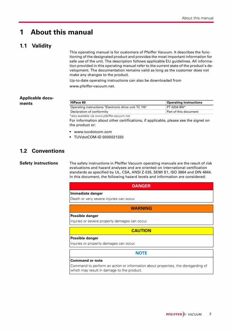
Safety instructions The safety instructions in Pfeiffer Vacuum operating manuals are the result of risk
evaluations and hazard analyses and are oriented on international certification
standards as specified by UL, CSA, ANSI Z-535, SEMI S1, ISO 3864 and DIN 4844.
In this document, the following hazard levels and information are considered:
HiPace 80 Operating instructions
Operating instructions "Electronic drive unit TC 110" PT 0204 BN*
Declaration of conformity Part of this document
DANGER
Immediate danger
Death or very severe injuries can occur.
WARNING
Possible danger
Injuries or severe property damages can occur.
CAUTION
Possible danger
Injuries or property damages can occur.
NOTE
Command or note
Command to perform an action or information about properties, the disregarding of which may result in damage to the product.
3
About this manual
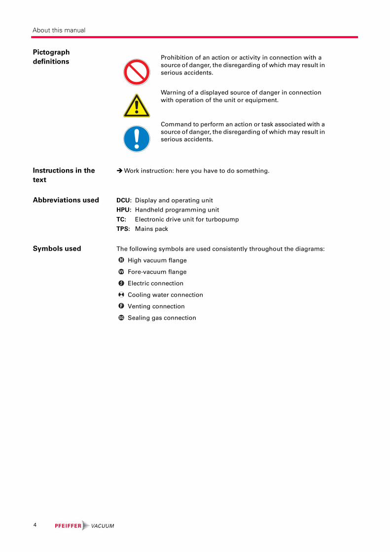
Pictograph
definitions
Instructions in the
text
Work instruction: here you have to do something.
Abbreviations used DCU: Display and operating unit
HPU: Handheld programming unit
TC: Electronic drive unit for turbopump
TPS: Mains pack
Symbols used The following symbols are used consistently throughout the diagrams:
High vacuum flange
Fore-vacuum flange
Electric connection
Cooling water connection
Venting connection
Sealing gas connection
Prohibition of an action or activity in connection with a
source of danger, the disregarding of which may result in
serious accidents.
Warning of a displayed source of danger in connection
with operation of the unit or equipment.
Command to perform an action or task associated with a
source of danger, the disregarding of which may result in
serious accidents.
H
VV
F
SG
4
Safety
2 Safety
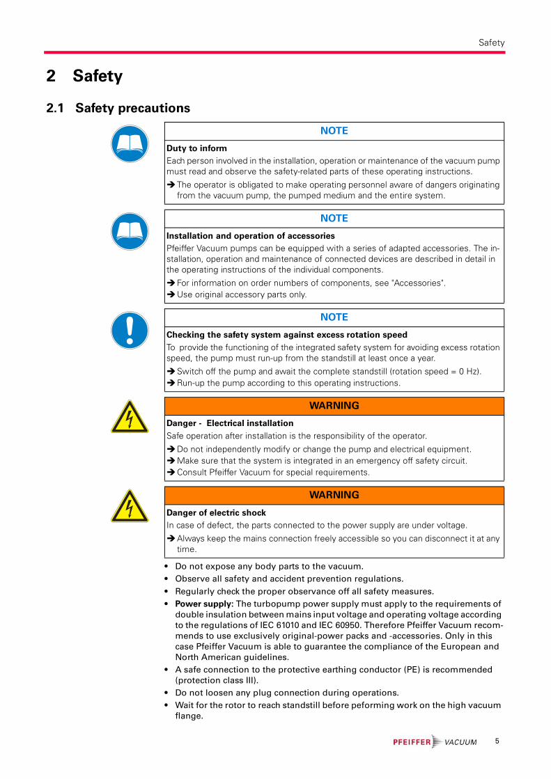
2.1 Safety precautions
• Do not expose any body parts to the vacuum.
• Observe all safety and accident prevention regulations.
• Regularly check the proper observance off all safety measures.
• Power supply: The turbopump power supply must apply to the requirements of
double insulation between mains input voltage and operating voltage according
to the regulations of IEC 61010 and IEC 60950. Therefore Pfeiffer Vacuum recom-
mends to use exclusively original-power packs and -accessories. Only in this
case Pfeiffer Vacuum is able to guarantee the compliance of the European and
North American guidelines.
• A safe connection to the protective earthing conductor (PE) is recommended
(protection class III).
• Do not loosen any plug connection during operations.
• Wait for the rotor to reach standstill before peforming work on the high vacuum
flange.
NOTE
Duty to inform
Each person involved in the installation, operation or maintenance of the vacuum pump must read and observe the safety-related parts of these operating instructions.
The operator is obligated to make operating personnel aware of dangers originating from the vacuum pump, the pumped medium and the entire system.
NOTE
Installation and operation of accessories
Pfeiffer Vacuum pumps can be equipped with a series of adapted accessories. The in-stallation, operation and maintenance of connected devices are described in detail in the operating instructions of the individual components.
For information on order numbers of components, see "Accessories".Use original accessory parts only.
NOTE
Checking the safety system against excess rotation speed
To provide the functioning of the integrated safety system for avoiding excess rotation speed, the pump must run-up from the standstill at least once a year.
Switch off the pump and await the complete standstill (rotation speed = 0 Hz).Run-up the pump according to this operating instructions.
WARNING
Danger - Electrical installation
Safe operation after installation is the responsibility of the operator.
Do not independently modify or change the pump and electrical equipment.Make sure that the system is integrated in an emergency off safety circuit.Consult Pfeiffer Vacuum for special requirements.
WARNING
Danger of electric shock
In case of defect, the parts connected to the power supply are under voltage.
Always keep the mains connection freely accessible so you can disconnect it at any time.
5
Safety
• Keep leads and cables well away from hot surfaces (> 70 °C).
• Never fill or operate turbopump with cleaning agent.
• Do not operate the turbopump with open high vacuum flange.
• Do not carry out any unauthorized modifications or conversions to the pump.
• When returning the turbopump observe the shipping instructions.
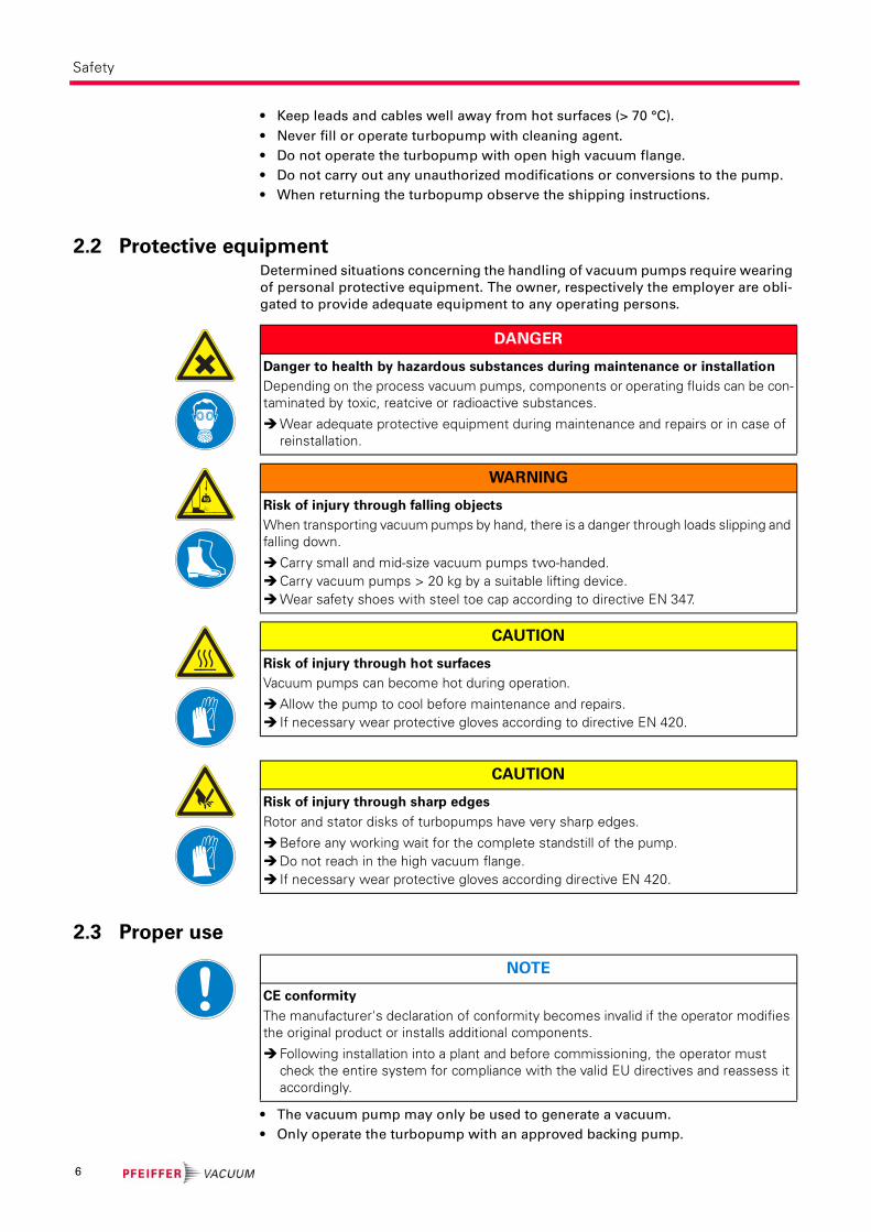
2.2 Protective equipmentDetermined situations concerning the handling of vacuum pumps require wearing
of personal protective equipment. The owner, respectively the employer are obli-
gated to provide adequate equipment to any operating persons.
2.3 Proper use
• The vacuum pump may only be used to generate a vacuum.
• Only operate the turbopump with an approved backing pump.
DANGER
Danger to health by hazardous substances during maintenance or installation
Depending on the process vacuum pumps, components or operating fluids can be con-taminated by toxic, reatcive or radioactive substances.
Wear adequate protective equipment during maintenance and repairs or in case of reinstallation.
kg
WARNING
Risk of injury through falling objects
When transporting vacuum pumps by hand, there is a danger through loads slipping and falling down.
Carry small and mid-size vacuum pumps two-handed.Carry vacuum pumps > 20 kg by a suitable lifting device.Wear safety shoes with steel toe cap according to directive EN 347.
CAUTION
Risk of injury through hot surfaces
Vacuum pumps can become hot during operation.
Allow the pump to cool before maintenance and repairs. If necessary wear protective gloves according to directive EN 420.
CAUTION
Risk of injury through sharp edges
Rotor and stator disks of turbopumps have very sharp edges.
Before any working wait for the complete standstill of the pump.Do not reach in the high vacuum flange. If necessary wear protective gloves according directive EN 420.
NOTE
CE conformity
The manufacturer's declaration of conformity becomes invalid if the operator modifies the original product or installs additional components.
Following installation into a plant and before commissioning, the operator must check the entire system for compliance with the valid EU directives and reassess it accordingly.
6

Safety
2.4 Improper useImproper use will cause all claims for liability and warranties to be forfeited. Im-
proper use is deemed to be all use for purposes deviating from those mentioned
above, especially:
• Pumping of corrosive or explosive media.
• Pumping of condensing vapors.
• Pumping of liquids.
• Pumping of dusts.
• Operation with improper high gas throughput.
• Operation with improper high fore-vacuum pressures.
• Operation with improper gas mode.
• Operation with improper high levels of insulated heat input.
• Venting with improper high venting rates.
• Use of the vacuum pump to generate pressure.
• The operation of the devices in potentially radioactive areas.
• Operation in potentially explosive areas.
• The operation of the devices in systems where the turbopumps are subjected to
impact-like stress and vibrations or the effect of periodically occurring forces.
• The use of accessories, which are not named in this manual.
warranty seal NOTE
Closure seal
The product is sealed at the factory. Damaging or removal of a closure seal leads to the loss of liability and warranty entitlements.
Do not open the product within its warranty period!For process-related shorter maintenance intervals please contact the Pfeiffer Vacu-
um Service.
7

Transport and storage
3 Transport and storage
3.1 Transport
Reuse the transport container. Vacuum pumps should be transported or shipped
in the original packing only.
Only remove the protective covers from the high vacuum and the fore-vacuum
side immediately before connection.
Keep the original protective covers.
Always transport the turbopump in an upright position.
3.2 Storage
Close the flange openings by using the original protective covers.
Close further connection ports by using the corresponding protective covers.
Store the pump only indoors at temperatures between -25 °C and +55 °C.
In rooms with moist or aggressive atmospheres, the pump must be airproof
shrink-wrapped in a plastic bag together with a bag of desiccant.
8
Product description
4 Product description
4.1 Product identification
Pump types The product designations of Pfeiffer vacuum turbomolecular pumps are self-ex-
planatory and permit conclusions about the different versions. The product desig-
nation consists of a family designation (1), the size (2), which is oriented on the
pumping speed, and if applicable the additional properties (3) of the pump.
HiPace(1) 80(2) (3)
Pump features
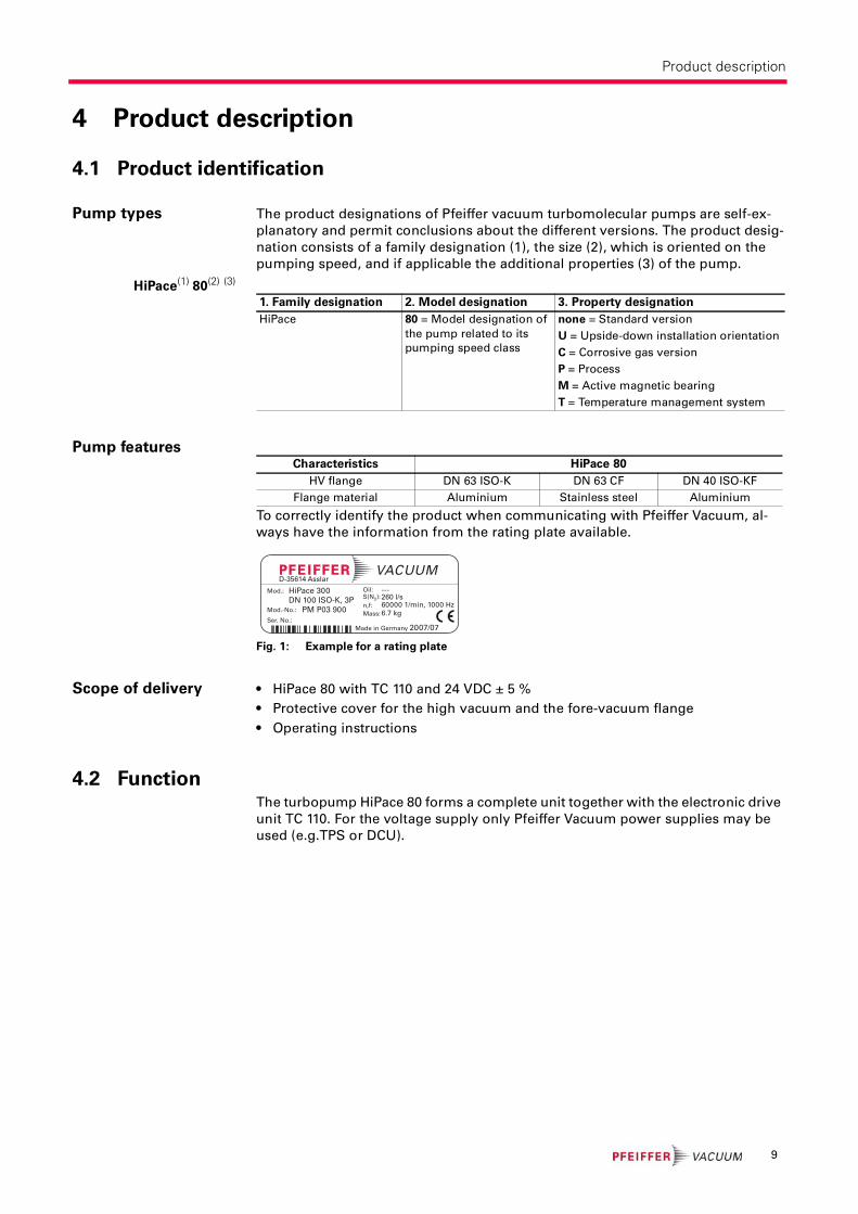
To correctly identify the product when communicating with Pfeiffer Vacuum, al-
ways have the information from the rating plate available.
Fig. 1: Example for a rating plate
Scope of delivery • HiPace 80 with TC 110 and 24 VDC ± 5 %
• Protective cover for the high vacuum and the fore-vacuum flange
• Operating instructions
4.2 FunctionThe turbopump HiPace 80 forms a complete unit together with the electronic drive
unit TC 110. For the voltage supply only Pfeiffer Vacuum power supplies may be
used (e.g.TPS or DCU).
1. Family designation 2. Model designation 3. Property designation
HiPace 80 = Model designation of
the pump related to its
pumping speed class
none = Standard version
U = Upside-down installation orientation
C = Corrosive gas version
P = Process
M = Active magnetic bearing
T = Temperature management system
Characteristics HiPace 80
HV flange DN 63 ISO-K DN 63 CF DN 40 ISO-KF
Flange material Aluminium Stainless steel Aluminium
Mod.:
Mod.-No.:
Ser. No.:
Oil:S(N2):n,f:
Made in Germany 2007/07
HiPace 300DN 100 ISO-K, 3P
PM P03 900
---260 l/s60000 1/min, 1000 Hz
Mass: 6.7 kg
D-35614 Asslar
9
Product description
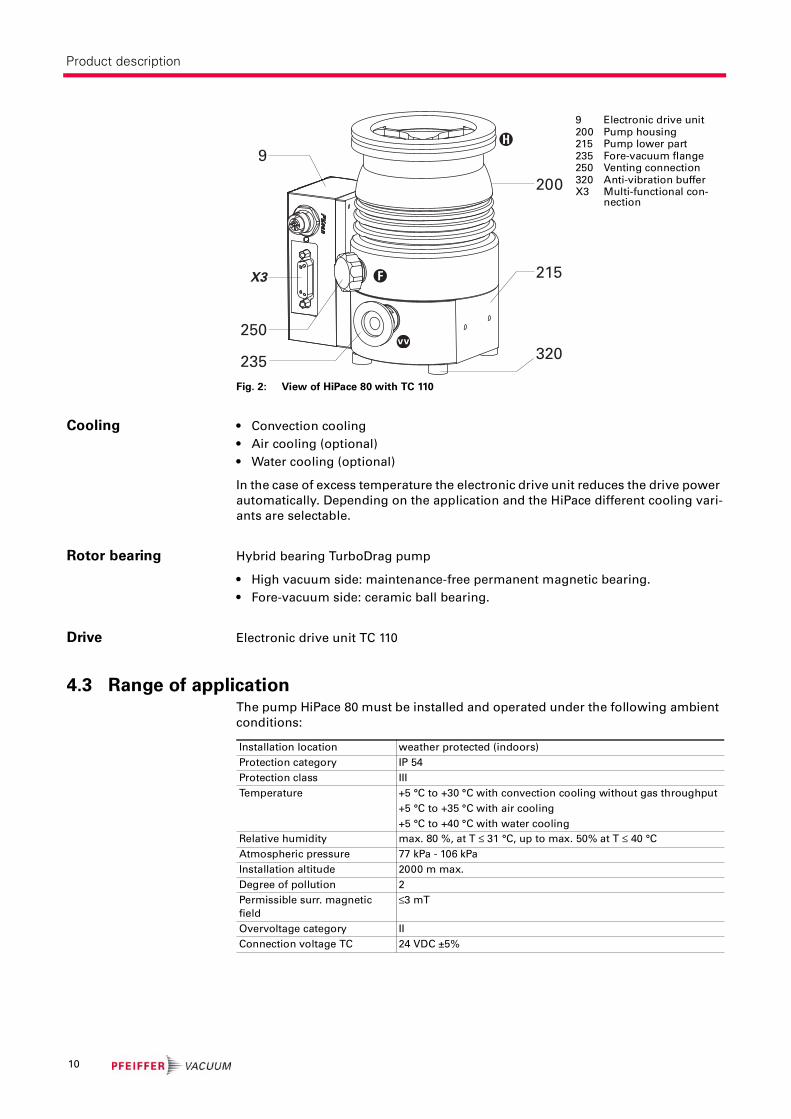
Fig. 2: View of HiPace 80 with TC 110
Cooling • Convection cooling
• Air cooling (optional)
• Water cooling (optional)
In the case of excess temperature the electronic drive unit reduces the drive power
automatically. Depending on the application and the HiPace different cooling vari-
ants are selectable.
Rotor bearing Hybrid bearing TurboDrag pump
• High vacuum side: maintenance-free permanent magnetic bearing.
• Fore-vacuum side: ceramic ball bearing.
Drive Electronic drive unit TC 110
4.3 Range of applicationThe pump HiPace 80 must be installed and operated under the following ambient
conditions:
9 Electronic drive unit200 Pump housing215 Pump lower part235 Fore-vacuum flange250 Venting connection320 Anti-vibration bufferX3 Multi-functional con-
nection
200
320235
9
250
F
H
215X3
Installation location weather protected (indoors)
Protection category IP 54
Protection class III
Temperature +5 °C to +30 °C with convection cooling without gas throughput
+5 °C to +35 °C with air cooling
+5 °C to +40 °C with water cooling
Relative humidity max. 80 %, at T ≤ 31 °C, up to max. 50% at T ≤ 40 °C
Atmospheric pressure 77 kPa - 106 kPa
Installation altitude 2000 m max.
Degree of pollution 2
Permissible surr. magnetic
field
≤3 mT
Overvoltage category II
Connection voltage TC 24 VDC ±5%
10

Installation
5 Installation
5.1 Set-upWhen installing the pump, observe the following conditions:
• The ambient conditions specified for the area of use.
• When using a casing heating and a water cooling unit the temperature of the
connected flange of the vacuum chamber must not exceed 120 °C.
• The pump may be fastened to the floor only after consultation with Pfeiffer Vac-
uum.
• It is not allowed to operate the device in systems where impact-like stresses and
vibrations or periodically forces occur.
5.2 Preparatory work
Ensure sufficient cooling for the turbopump.
Where magnetic fields > 3 mT are involved, a suitable shielding must be used.
Check installation location and consult Pfeiffer Vacuum if needed!
The maximum permissible rotor temperature for the turbopump is 90 °C. If high
temperatures arise for process reasons, the radiated heat input must not exceed
0.9 W. Install suitable screening sheets, if necessary (design information on re-
quest).
5.3 Assembly
• Ensure the greatest possible cleanliness when installing any high vacuum parts.
Unclean components prolong the pump-down time.
• All flange components must be grease-free, dust-free and dry at installation.
• The operating fluid reservoir is already installed and filled for the turbopump
HiPace 80.
Earthquake safety An earthquake can result in contact with the safety bearings. All forces occuring
hereby are safely absorbed by the properly installed flange connections.
The vacuum chamber must be secured by the customer against shifting and tip-
ping.
DANGER
Danger from the turbopump being torn-off
In case of sudden blocking of the rotor, torques of up to 620 Nm can occur, which can lead with incorrect attachment to tearing the turbopump off. The energy released there-by can hurl the entire pump or fragments from their inside around the area. This can cause severest injuries (possibly resulting in death) and large property damage.
Precisely follow installation instructions.Only use Pfeiffer Vacuum original components (accessories) for installation.
NOTE
Installation and operation of accessories
Pfeiffer Vacuum pumps can be equipped with a series of adapted accessories. The in-stallation, operation and maintenance of connected devices are described in detail in the operating instructions of the individual components.
For information on order numbers of components, see "Accessories".Use original accessory parts only.
11

Installation
Use of a splinter
shield or protection
screen
The installation of a Pfeiffer Vacuum centering ring with splinter shield or protec-
tion screen in the high vacuum flange protects the turbopump against foreign bod-
ies coming from the chamber. The volume flow rate is reduced.
Vibration damper
Mounting orientation When using dry backing pumps Pfeiffer Vacuum HiPace pumps are designed for in-
stallation in any orientation.
Support pipes in front of the vacuum pump or remove them. No force from the
pipe system may be exerted on the fixed pump.
To avoid contamination via the fore-vacuum line when using oil-sealed backing
pumps the fore-vacuum flange should always point vertically downward (± 25°).
The maximum axial loading capacity of the high vacuum flange is 200 N (equals
20 kg). A one-sided load on the high vacuum flange is not permitted.
Fig. 3: Example: How to secure against shifting and tipping by external tremors
SC SC
SC
SC SCSC = Safety Connection
Vacuum chamber
Reduced volume flow rate in %
H2 He N2 Ar
Splinter shield DN 40 6 9 17 18
Splinter shield DN 63 3 6 15 16
Protection screen DN 63 1 1 4 4
DANGER
Danger from the turbopump and vibration dumper being torn-off
In case of sudden blocking of the rotor, an applied vibration dumper cannot compensate any of the occurring forces. There is a danger of the turbopump being torn-off and there-by resulting severest injuries and property damages. Applicable safeguards must be taken to compensate possible occurring torques.
Definetely consult with Pfeiffer Vacuum.Do not exceed the max. permissible temperature at the vibration dumper (100° C).
Fig. 4: Recommended orientation of the fore-vacuum flange
25° maxVV VV
12
Installation
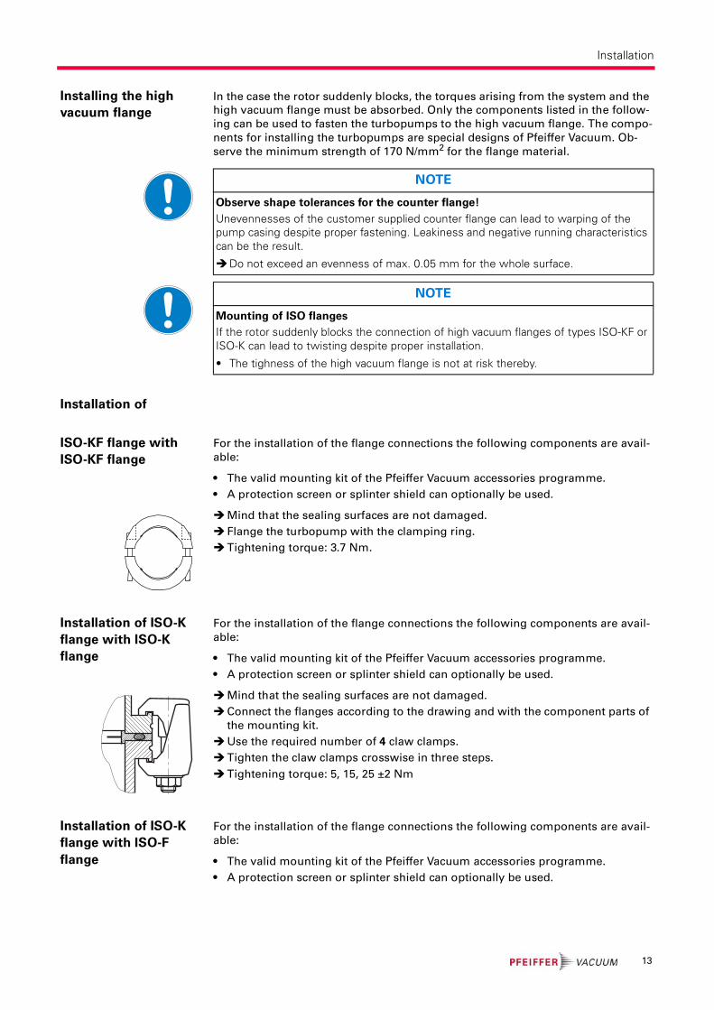
Installing the high
vacuum flange
In the case the rotor suddenly blocks, the torques arising from the system and the
high vacuum flange must be absorbed. Only the components listed in the follow-
ing can be used to fasten the turbopumps to the high vacuum flange. The compo-
nents for installing the turbopumps are special designs of Pfeiffer Vacuum. Ob-
serve the minimum strength of 170 N/mm2 for the flange material.
Installation of
ISO-KF flange with
ISO-KF flange
For the installation of the flange connections the following components are avail-
able:
• The valid mounting kit of the Pfeiffer Vacuum accessories programme.
• A protection screen or splinter shield can optionally be used.
Mind that the sealing surfaces are not damaged.
Flange the turbopump with the clamping ring.
Tightening torque: 3.7 Nm.
Installation of ISO-K
flange with ISO-K
flange
For the installation of the flange connections the following components are avail-
able:
• The valid mounting kit of the Pfeiffer Vacuum accessories programme.
• A protection screen or splinter shield can optionally be used.
Mind that the sealing surfaces are not damaged.
Connect the flanges according to the drawing and with the component parts of
the mounting kit.
Use the required number of 4 claw clamps.
Tighten the claw clamps crosswise in three steps.
Tightening torque: 5, 15, 25 ±2 Nm
Installation of ISO-K
flange with ISO-F
flange
For the installation of the flange connections the following components are avail-
able:
• The valid mounting kit of the Pfeiffer Vacuum accessories programme.
• A protection screen or splinter shield can optionally be used.
NOTE
Observe shape tolerances for the counter flange!
Unevennesses of the customer supplied counter flange can lead to warping of the pump casing despite proper fastening. Leakiness and negative running characteristics can be the result.
Do not exceed an evenness of max. 0.05 mm for the whole surface.
NOTE
Mounting of ISO flanges
If the rotor suddenly blocks the connection of high vacuum flanges of types ISO-KF or ISO-K can lead to twisting despite proper installation.
• The tighness of the high vacuum flange is not at risk thereby.
13

Installation
Mind that the sealing surfaces are not damaged.
Connect the flanges according to the drawing and with the component parts of
the mounting kit.
Use the required number of 4 claw grips.
Tighten the claw grips crosswise in three steps.
Tightening torque: 3, 10, 16 ±1 Nm.
Installation of CF-
flanges
The connection types for installation of CF to CF flange are "stud screw and blind
hole" as well as "hex screw and through hole". The following elements are re-
quired:
• The valid mounting kit of the Pfeiffer Vacuum accessories programme.
• A copper seal
• A protection screen or splinter shield can optionally be used.
Stud screw and blind hole
If used: Insert protective screen or splinter shield with the clamping lugs down-
ward into the high vacuum flange of the turbopump.
Place the seal exactly in the hollow.
Connect the flange using 8 stud screws (M8) with washers and nuts and tighten
circularly with a torque of 22 ±2 Nm. After this, check the torque, since flowing
of the sealing material may make it necessary to tighten the screws.
Hexagon screw and through hole
If used: Insert protective screen or splinter shield with the clamping lugs down-
ward into the high vacuum flange of the turbopump.
Place the seal exactly in the hollow.
Connect the flange using 8 hex screws (M8) with washers and nuts and tighten
circularly with a torque of 22 ±2 Nm. After this, check the torque, since flowing
of the sealing material may make it necessary to tighten the screws.
NOTE
Preservation of sealing capacity
Observe the following to preserve sealing capacity:
Touch seals only with gloves.Make sure sealing lips are undamaged.
14

Installation
5.4 Connections to the turbopump
Electronic drive unit Turbopumps with integrated electronic drive unit are designed for various applica-
tions. Therefore different connection panels are available for the TC 110.
• TC 110 in standard version
• TC 110 PB for Profibus linking
• TC 110 E74 in dependence on specification SEMI E74
• TC 110 DN for DeviceNet linking
Detailed description for function, configuration and operation with the respective
connection panel are given in the specific operating instructions for the electronic
drive unit.
Connecting the
power supply
For voltage supply of the electronic drive unit TC 110, only use original power sup-
plies (e.g. TPS 110 or DCU 110). Use of other power supplies only after consultation
with Pfeiffer Vacuum. Connecting cables are available from the Pfeiffer Vacuum ac-
cessory programme.
Make sure that the turbopump has the correct supply voltage.
Fig. 5: Connecting the TC 110 to a power supply using a Pfeiffer Vacuum connecting cable
Switch off switch S1 on the mains pack (position "0").
Place and fix the connecting cable with the 15-pole mating plug into the connec-
tion "X3" on the electronic drive unit.
Insert the connection cable with the plug in the connection "DC out" on the pow-
er supply and close the bayonet lock.
When using a Pfeiffer Vacuum display and control unit:
Connecting cable Function
TC 110 - TPS/DCU 110/180
with bridges, RS 485
• Voltage supply via power supply pack• Automatic start by bridges on pins 2, 5, 7• Connection to a display and control unit via RS 485
TC 110 - TPS/DCU 110/180
with accessory ports, RS 485
• Voltage supply via power supply pack• Accessory connection via M8 plugs• Connection to a display and control unit via RS 485
TC 110 - TPS 110/180
with bridges
• Voltage supply via power supply pack• Automatic start by bridges on pins 2, 5, 7
TC 110 - TPS 110/180
with bridges, with accessory
ports
• Voltage supply via power supply pack• Automatic start by bridges on pins 2, 5, 7• Accessory connection via M8 plugs
WARNING
Danger of electric shock
In case of defect, the parts connected to the power supply are under voltage.
Always keep the mains connection freely accessible so you can disconnect it at any time.
DC out
S1
TPS / DCU TC 110
X3
RS485(optional)
accessory(optional)
15
Installation
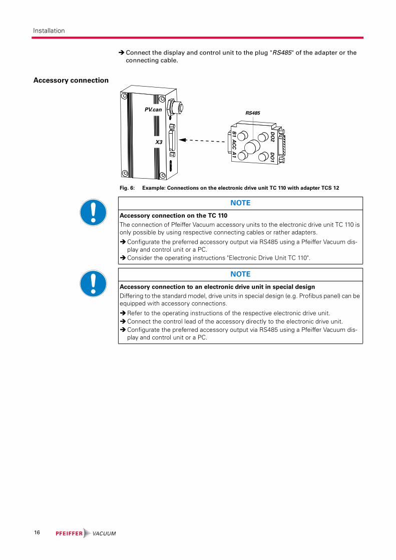
Connect the display and control unit to the plug "RS485" of the adapter or the
connecting cable.
Accessory connection
Fig. 6: Example: Connections on the electronic drive unit TC 110 with adapter TCS 12
X3
RS485PV.can
B1 A
CC
A1
DO
2D
O1
NOTE
Accessory connection on the TC 110
The connection of Pfeiffer Vacuum accessory units to the electronic drive unit TC 110 is only possible by using respective connecting cables or rather adapters.
Configurate the preferred accessory output via RS485 using a Pfeiffer Vacuum dis-play and control unit or a PC.
Consider the operating instructions "Electronic Drive Unit TC 110".
NOTE
Accessory connection to an electronic drive unit in special design
Differing to the standard model, drive units in special design (e.g. Profibus panel) can be equipped with accessory connections.
Refer to the operating instructions of the respective electronic drive unit.Connect the control lead of the accessory directly to the electronic drive unit.Configurate the preferred accessory output via RS485 using a Pfeiffer Vacuum dis-
play and control unit or a PC.
16
Installation
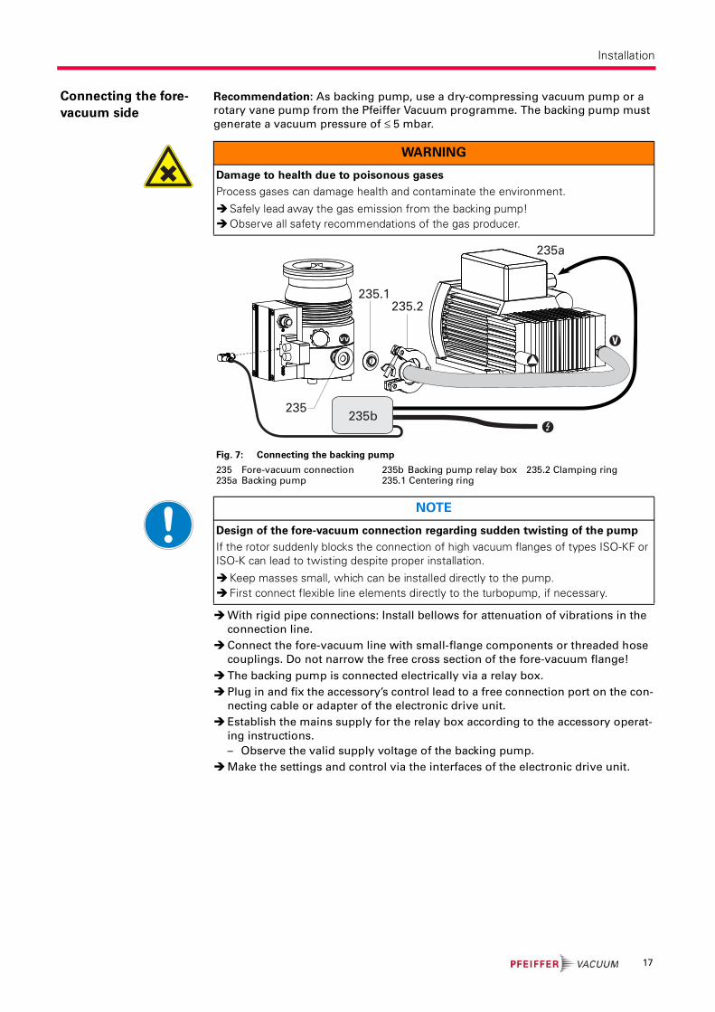
Connecting the fore-
vacuum side
Recommendation: As backing pump, use a dry-compressing vacuum pump or a
rotary vane pump from the Pfeiffer Vacuum programme. The backing pump must
generate a vacuum pressure of ≤ 5 mbar.
With rigid pipe connections: Install bellows for attenuation of vibrations in the
connection line.
Connect the fore-vacuum line with small-flange components or threaded hose
couplings. Do not narrow the free cross section of the fore-vacuum flange!
The backing pump is connected electrically via a relay box.
Plug in and fix the accessory’s control lead to a free connection port on the con-
necting cable or adapter of the electronic drive unit.
Establish the mains supply for the relay box according to the accessory operat-
ing instructions.
– Observe the valid supply voltage of the backing pump.
Make the settings and control via the interfaces of the electronic drive unit.
WARNING
Damage to health due to poisonous gases
Process gases can damage health and contaminate the environment.
Safely lead away the gas emission from the backing pump!Observe all safety recommendations of the gas producer.
Fig. 7: Connecting the backing pump
235 Fore-vacuum connection235a Backing pump
235b Backing pump relay box235.1 Centering ring
235.2 Clamping ring
V
235b
235a
235.2235.1
235
NOTE
Design of the fore-vacuum connection regarding sudden twisting of the pump
If the rotor suddenly blocks the connection of high vacuum flanges of types ISO-KF or ISO-K can lead to twisting despite proper installation.
Keep masses small, which can be installed directly to the pump.First connect flexible line elements directly to the turbopump, if necessary.
17
Installation
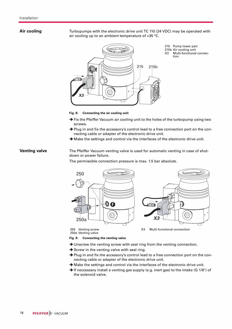
Air cooling Turbopumps with the electronic drive unit TC 110 (24 VDC) may be operated with
air cooling up to an ambient temperature of +35 °C.
Fig. 8: Connecting the air cooling unit
Fix the Pfeiffer Vacuum air cooling unit to the holes of the turbopump using two
screws.
Plug in and fix the accessory’s control lead to a free connection port on the con-
necting cable or adapter of the electronic drive unit.
Make the settings and control via the interfaces of the electronic drive unit.
Venting valve The Pfeiffer Vacuum venting valve is used for automatic venting in case of shut-
down or power failure.
The permissible connection pressure is max. 1.5 bar absolute.
Fig. 9: Connecting the venting valve
Unscrew the venting screw with seal ring from the venting connection.
Screw in the venting valve with seal ring.
Plug in and fix the accessory’s control lead to a free connection port on the con-
necting cable or adapter of the electronic drive unit.
Make the settings and control via the interfaces of the electronic drive unit.
If neccessary install a venting gas supply (e.g. inert gas) to the intake (G 1/8") of
the solenoid valve.
215 Pump lower part215b Air cooling unitX3 Multi-functional connec-
tion
X3
215 215b
250 Venting screw250a Venting valve
X3 Multi-functional connection
F
250
250a X3
18

Installation
Heating jacket The turbopump and vacuum chamber can be heated to reach the final pressure
more quickly. Use of a heating jacket is only permissible for pumps with the high
vacuum flange in stainless steel design. The heating duration depends on the de-
gree of contamination as well as the final pressure to be reached and should be at
least 4 hours.
• When using a casing heating and a water cooling unit the temperature of the
connected flange of the vacuum chamber must not exceed 120 °C.
• The maximum permissible rotor temperature for the turbopump is 90 °C. If high
temperatures arise for process reasons, the radiated heat input must not exceed
0.9 W. Install suitable screening sheets, if necessary (design information on re-
quest).
Bend open the outer heating jacket on the tensioning strap and place it
sidewards on to the cylindrical segment of the pump casing.
– Do not bend the heating straps!
– The heating jacket must seat completely on the casing segment.
Fix the heating jacket with the fixing screw on the casing.
– Observe the tightening torque for the fixing screw!
Tightening torques for fixing screws of heating jackets
Plug in and fix the accessory’s control lead to a free connection port on the con-
necting cable or adapter of the electronic drive unit.
CAUTION
Dangerous excess temperatures
Process-related high temperatures can result in impermissible excess temperatures and thus damage to the turbopump.
Always use water cooling when a casing heating is used or when the pump is con-nected to a heated vacuum chamber.
WARNING
Danger of burns
High temperatures arise when the turbopump or vacuum chamber are baked out. As a result, there is a danger of burns from touching hot parts, even after the casing heating is switched off!
Thermally insulate heating jacket, pump housing and vacuum chamber, if possible during installation.
Do not touch heating jacket, pump casing and vacuum chamber during bake out.
Fig. 10: Connecting the heating jacket
200 Pump casing200a Heating jacket
200b Fixing screw200c Heating relay box
200d Warning sticker
Fixing screw Tightening torque in cold condition
Tightening torque during the heating-up
Singular retightening af-ter the cooling down
M5 6 Nm 7 Nm 7 Nm
M6 11 Nm 12 Nm 12 Nm
H
200a200d
200b2x
200c
200
X3
19

Installation
Make the settings and control via the interfaces of the electronic drive unit.
Establish the mains supply for the relay box according to the accessory operat-
ing instructions.
Sealing gas connec-
tion
The turbopump must be operated with sealing gas to protect it, such as in the case
of unclean processes or high gas throughput. The supply is made via a sealing gas
valve or alternatively via a sealing gas throttle without control. The activation of
the control valve for the sealing gas connection is not pre-installed in the electronic
drive unit and has to be configured via their interfaces.
The permissible connection pressure is max. 1.5 bar absolute.
• When operating the pump with more than 50 % of the maximum gas through-
put, sealing gas must be used to ensure rotor cooling.
• The sealing gas flow rate amounts 7.5 - 9.5 sccm for the HiPace 80.
Sealing gas supply without control valve
Fig. 11: Connecting the sealing gas throttle
Unscrew the locking screw with seal ring out of the sealing gas connection.
Screw the sealing gas throttle with sealing ring into the sealing gas connection.
Sealing gas supply with control valve
Fig. 12: Connecting the sealing gas valve
Unscrew the locking screw with seal ring out of the sealing gas connection.
Screw the sealing gas valve with seal ring into the sealing gas connection.
Plug in and fix the accessory’s control lead to a free connection port on the con-
necting cable or adapter of the electronic drive unit.
Make the settings and control via the interfaces of the electronic drive unit.
Install the sealing gas supply (e.g. inert gas) via a connection adapter or on the
inlet side (G 1/8") of the control valve.
215a Sealing gas connection248 Locking screw248a Sealing gas throttle
215a Sealing gas connection248 Locking screw248a Sealing gas valveX3 Multi-functional connection
SG
248
248b
215a
SG
248
X3
248a
215a
20

Installation
Water cooling As an option turbopumps HiPace 80 with TC 110 can be equipped with water cool-
ing.
• In case of increased backing pressure (> 0.1 mbar) and/or operation with gas
throughputs, either air or water cooling may be used.
• Generally use water cooling if the ambient temperature is > +35 °C.
Cooling water requirements
Connecting to a cooling water system
Fig. 13: Connecting the cooling water
Fix the water cooling unit sideways on the pump lower part.
Insert hoses for the water cooling fore- and return-line as far as they will go in
one cooling water connection each.
Recommendation: install dirt trap in the fore-line.
Cooling water connection Socket connection
Hose lines External diameter 8 mm
Internal diameter 6 mm
Cooling water quality filtrated, mechanically clean, optically clear, no turbidity,
no sediments, chemically neutral
Oxygen content max. 4 mg/kg
Chloride content max. 100 mg/kg
Water hardness max. 10 °dH
12.53 °e
17.8 °fH
178 ppm CaC03
Consumption of potassium perman-
ganate max.
10 mg/kg
Carbon dioxide content max. undetectable
Ammonia content max. undetectable
pH-value 7 - 9
Fore-line overpressure max. 6 bar
Cooling water temperature > dew point, max. 25 °C
Cooling water consumption at max.
gas throughput
75 l/h
215 Pump lower part,215c Water cooling unit215d Dirt trap
215
215c
215d
21
Operation
6 Operation
6.1 CommissioningThe following important settings are programmed in the electronic drive unit ex
factory.
• Parameter [P:700] Set value run-up time: 8 min
• Parameter [P:027] Gas mode: 0 = heavy gases
• Parameter [P:701] Rotation speed switchpoint: 80% of the nominal roation speed
• Parameter [P:720] Venting rotation speed at delayed venting: 50% of the nominal
rotation speed
• Parameter [P:721] Venting time: 3600 s
• Parameter [P:708] Set value power consumption 70 % (may be only reduced)
When water cooling is used: Open cooling water supply and check the flow.
When sealing gas is used: Open the sealing gas supply and check the flow.
Establish the mains for the power supply.
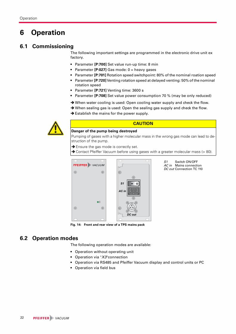
Fig. 14: Front and rear view of a TPS mains pack
6.2 Operation modesThe following operation modes are available:
• Operation without operating unit
• Operation via "X3"connection
• Operation via RS485 and Pfeiffer Vacuum display and control units or PC
• Operation via field bus
CAUTION
Danger of the pump being destroyed
Pumping of gases with a higher molecular mass in the wrong gas mode can lead to de-struction of the pump.
Ensure the gas mode is correctly set.Contact Pfeiffer Vacuum before using gases with a greater molecular mass (> 80).
S1 Switch ON/OFFAC in Mains connectionDC out Connection TC 110
DC out
S1
AC in
22
Operation
6.3 Function description
Operation without
operating unit
For operation without the control unit, the respective connecting cable "with
bridges" must be in the "X3" connection on the TC 110.
Switch on the supply voltage with switch S1 on the power supply.
After operating voltage is applied, the TC 110 performs a self-test to check the sup-
ply voltage. Once the self test has been successfully completed on the TC 110, the
turbopump and the backing pump - if connected - begin to operate.
Operation via "X3"
connection
Remote control options are provided via the 15-pole D-Sub connector with the des-
ignation ”X3“ on the electronic drive unit.
Consider the following manuals for the operation via remote control:
• Operating instructions "Electronic drive unit TC 110"
Operation with DCU
or HPU
Consider the following manuals for the operation via Pfeiffer Vacuum display
and control units:
• Operating instructions "DCU"
• Operating instructions "HPU"
• Operating instructions "Electronic drive unit TC 110"
Connect the display and control unit to the plug "RS485" of the adapter or the
connecting cable.
Switch on the supply voltage with switch S1 on the power supply or on the
DCU 110.
Settings are possible via the RS485 by using DCU, HPU or PC.
Operation via field
bus
Integrating and operating Pfeiffer Vacuum turbopumps in the customer's field bus
system is possible for electronic drive units with a corresponding field bus panel.
Consider the following manuals for the operation via field bus:
• Operating instructions for the electronic drive unit with the respective con-
nection panel
WARNING
Danger due to open high vacuum flange
The rotor of the turbopump turns at high speed. If the high vacuum flange is open, there is a danger of cut injuries and that the pump can be destroyed by objects falling into it.
Never operate the pump with an open high vacuum flange.
CAUTION
Automatic start
After bridging the contacts Pin 2, 5, 7 on the connection "X3" or using a connecting ca-ble "with bridges" and setting up the supply voltage, the turbopump will run up imme-diately.
Switch on the mains supply on the turbopump immediately before operation.
23

Operation
6.4 Monitoring of the operation conditions
Operating mode dis-
play via LED
LEDs in the front panel of the electronic drive unit show basic operating conditions
of the turbopump. A differentiated malfunction and warning display is possible
only for operation with DCU or HPU.
Temperature monitor-
ing
The drive power is reduced in case of impermissible motor temperature or imper-
missibly high housing temperature. This can cause falling below the rotation
speed switchpoint and so result in turning off the turbopump.
6.5 Switching off and venting
Switching off After the turbopump is switched off, it must be vented to avoid contamination due
to particles streaming back from the fore-vacuum area.
Close the fore-vacuum line: Switch off the backing pump or close a fore-vacuum
valve.
Switch off the turbopump on the control unit or via remote control.
Venting (possibilities, see below)
For water cooling: Shut off the water supply.
Venting Manually Venting
Open the venting screw (included) in the venting connection of the turbopump
about one turn.
Venting with Pfeiffer Vacuum Venting Valve
Enable venting via the functions of the electronic drive unit.
Settings are possible via the RS485 by using DCU, HPU or PC.
1)When mains power is restored the venting procedure is aborted.
Basic information for the rapid venting
Venting of the vacuum chamber in two steps. Ask for details on individual solutions
from Pfeiffer Vacuum.
Vent for 20 seconds at a rate of pressure rise of max. 15 mbar/s.
– The valve cross section for the venting rate of 15 mbar/s must be adapted to
the size of the vacuum chamber.
– For small vacuum chambers, use the Pfeiffer Vacuum venting valve.
Then vent with an additional venting valve of any desired size.
LED Symbol Steady OFF Flashing
(1/12 s active)
Blinking
(1/2 s active)
Steady ON
Green insufficient
power supply
Pumping station
"OFF"
Rotation speed ≤ 1Hz
Pumping station "OFF"
Rotation speed > 1 Hz
Pumping sta-
tion "ON"
Yellow no warning Warning
Red no malfunc-
tion
Malfunction
Venting rotation speed Switch off the pumping station Mains power failure1)
50% of the nominal rotation
speed
Venting valve opens for 3600 s (1 h,
works setting)
Venting valve opens for
3600 s (1 h, works setting)
24
Maintenance / replacement
7 Maintenance / replacement
7.1 Maintenance intervals and responsibilities
Clean the turbopump externally with a lint-free cloth and little industrial alcohol.
Replace the operating fluid reservoir and electronic drive unit yourself.
Change the operating fluid reservoir at least every 4 years.
Change the turbopump bearing at least every 4 years.
– Contact Pfeiffer Vacuum Service.
Clarify shorter maintenance intervals for extreme loads or impure processes
with Pfeiffer Vacuum Service.
For all other cleaning, maintenance or repair work, please contact your Pfeiffer
Vacuum service location.
7.2 Replacing the operating fluid reservoir
Turn off the vacuum pump, vent to atmospheric pressure and allow to cool, if
necessary.
Remove the vacuum pump from the system, if necessary.
Close the flange openings by using the original protective covers.
Turn the turbopump over onto the closed high vacuum flange.
WARNING
Contamination of parts and operating fluid by pumped media is possible.
Poisoning hazard through contact with materials that damage health.
In the case of contamination, carry out appropriate safety precautions in order to pre-vent danger to health through dangerous substances.
Decontaminate affected parts before carrying out maintenance work.
NOTE
Disclaimer of liability
Pfeiffer Vacuum accepts no liability for personal injury or material damage, losses or op-erating malfunctions due to improperly performed maintenance. The liability and war-ranty entitlement expires.
WARNING
Poisoning hazard through contact with materials that damage health.
The operating fluid reservoir and parts of the pump may contain toxic substances from the pumped media.
Dispose of operating fluid reservoir in accordance with the applicable regulations. Safety data sheet on request or under www.pfeiffer-vacuum.net
Prevent health hazards or environmental damage due to contamination by means of appropriate safety precautions.
Decontaminate affected parts before carrying out maintenance work.
NOTE
Lubricant filling
The lubricant reservoir is sufficiently filled with lubricant.
Do not add additional lubricant.
25
Maintenance / replacement
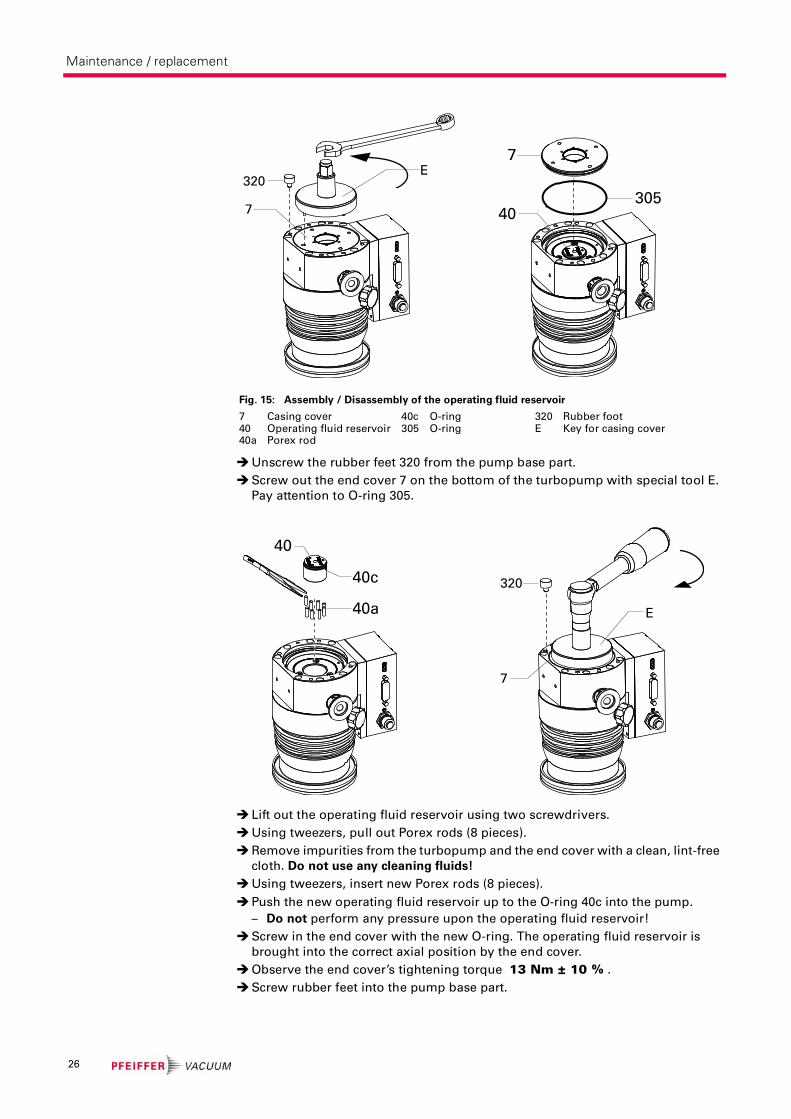
Unscrew the rubber feet 320 from the pump base part.
Screw out the end cover 7 on the bottom of the turbopump with special tool E.
Pay attention to O-ring 305.
Lift out the operating fluid reservoir using two screwdrivers.
Using tweezers, pull out Porex rods (8 pieces).
Remove impurities from the turbopump and the end cover with a clean, lint-free
cloth. Do not use any cleaning fluids!
Using tweezers, insert new Porex rods (8 pieces).
Push the new operating fluid reservoir up to the O-ring 40c into the pump.
– Do not perform any pressure upon the operating fluid reservoir!
Screw in the end cover with the new O-ring. The operating fluid reservoir is
brought into the correct axial position by the end cover.
Observe the end cover’s tightening torque 13 Nm ± 10 % .
Screw rubber feet into the pump base part.
Fig. 15: Assembly / Disassembly of the operating fluid reservoir
7 Casing cover40 Operating fluid reservoir40a Porex rod
40c O-ring 305 O-ring
320 Rubber footE Key for casing cover
7
E320
7
30540
40
40a
40c
7
E
320
26

Maintenance / replacement
7.3 Replacing the electronic drive unit
Fig. 16: Assembly / disassembly of the TC 110
Do not exercise any mechanical load on the electronic drive unit.
Turn off the vacuum pump, vent to atmospheric pressure and allow to cool, if
necessary.
Only seperate the pump and the electronic drive unit from each other after dis-
connecting the supply voltage and the complete standstill of the pump.
Remove the vacuum pump from the system, if necessary.
Unscrew Allen head screws (4 pieces) from the electronic drive unit.
Pull the electronic drive unit off the pump.
Screw on and connect new electronic drive unit to the turbopump.
– Tightening torque 0.6 - 0.8 Nm.
Rotation speed set
value
The typical nominal rotation speed of a turbopump is factory-set in the electronic
drive unit. If the electronic drive unit is replaced or a different pump type is used,
the reference set value of the nominal rotation speed must be confirmed. This pro-
cedure is part of a redundant safety system for avoiding excess rotation speeds.
Adjust the parameter [P:777] according to the pump type.
Alternatively: If no display and control unit is available, please use the "Speed-
Configurator" of the spare parts delivery.
CAUTION
Damages to the pump and drive
Even after the mains power is switched off, the subsequently running pump delivers electric power to the electronic drive unit. There is a danger of electric body contact by premature separating the pump from the electronic drive unit.
Never separate the electronic drive unit from the pump when the mains power is connected or the rotor is running.
NOTE
Operating parameters of the electronic drive unit
The factory operating parameters are always preset with replacement shipments.
The use of a HPU enables the storing and the reuse of an existing parameter record.Reset any individually changed application parameters.Refer to the manual "Pumping operations".
9 Electronic drive unit326 Allen head screw
9326
HiPace Nominal rotation speed confirmation [P:777]
10 / 60 / 80 1500 Hz
300 1000 Hz
27

Decommissioning
8 Decommissioning
8.1 Shutting down for longer periods
If the turbopump should be shut down for longer than a year:
Remove the vacuum pump from the system, if necessary.
Change the operating fluid reservoir.
Close the high vacuum flange of the turbopump.
Evacuate turbopump via the fore-vacuum flange.
Vent turbopump via the venting connection with oil-free, dry air or inert gas.
Close the flange openings by using the original protective covers.
Close further connection ports by using the corresponding protective covers.
Place pump upright on rubber feet.
Store the pump only indoors at temperatures between -25 °C and +55 °C.
In rooms with moist or aggressive atmospheres, the pump must be airproof
shrink-wrapped in a plastic bag together with a bag of desiccant.
8.2 Re-starting
Check turbopump for contamination and moisture.
Clean the turbopump externally with a lint-free cloth and little industrial alcohol.
If necessary, have Pfeiffer Vacuum Service clean the turbopump completely.
If necessary, have the bearings replaced. Take into account the total running
time.
Change the operating fluid reservoir.
Installation and commissioning in accordance with the operating instructions.
8.3 DisposalProducts or parts thereof (mechanical and electrical components, operating fluids,
etc.) may cause environmental burden.
Safely dispose of the materials according to the locally applicable regulations.
WARNING
Contamination of parts and operating fluid by pumped media is possible.
Poisoning hazard through contact with materials that damage health.
In the case of contamination, carry out appropriate safety precautions in order to pre-vent danger to health through dangerous substances.
Decontaminate affected parts before carrying out maintenance work.
CAUTION
Re-starting
The serviceability of the operating fluid of the turbopump without operation is a maxi-mum of 4 years. Before restarting after a shut-down of 4 years or longer, carry out the following work:
Replace the operating fluid reservoirReplace bearingsFollow the maintenance instructions and inform Pfeiffer Vacuum
28
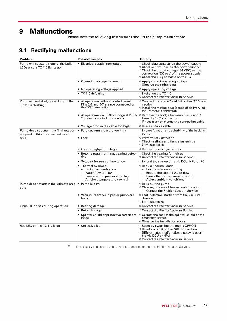
Malfunctions
9 MalfunctionsPlease note the following instructions should the pump malfunction:
9.1 Rectifying malfunctions
1) If no display and control unit is available, please contact the Pfeiffer Vacuum Service.
Problem Possible causes Remedy
Pump will not start; none of the built-in
LEDs on the TC 110 lights up
• Electrical supply interrupted Check plug contacts on the power supplyCheck supply lines on the power supplyCheck the output voltage (24 VDC) on the
connection "DC out" of the power supplyCheck the plug contacts on the TC
• Operating voltage incorrect Apply correct operating voltageObserve the rating plate
• No operating voltage applied Apply operating voltage
• TC 110 defective Exchange the TC 110Contact the Pfeiffer Vacuum Service
Pump will not start; green LED on the
TC 110 is flashing
• At operation without control panel: Pins 2-7 and 5-7 are not connected on the "X3" connection
Connect the pins 2-7 and 5-7 on the "X3" con-nection
Install the mating plug (scope of delivery) to the "remote" connection.
• At operation via RS485: Bridge at Pin 2-7 prevents control commands
Remove the bridge betwenn pins 2 and 7 from the "X3" connection
If necessary exchange the connecting cable.
• Voltage drop in the cable too high Use a suitable cable
Pump does not attain the final rotation-
al speed within the specified run-up
time
• Fore-vacuum pressure too high Ensure function and suitability of the backing pump
• Leak Perform leak detectionCheck sealings and flange fasteningsEliminate leaks
• Gas throughput too high Reduce process gas supply
• Rotor is rough-running, bearing defec-tive
Check the bearing for noisesContact the Pfeiffer Vacuum Service
• Setpoint for run-up time to low Extend the run-up time via DCU, HPU or PC
• Thermal overload:– Lack of air ventilation– Water flow too low– Fore-vacuum pressure too high– Ambient temperature too high
Reduce thermal loads– Ensure adequate cooling– Ensure the cooling water flow– Lower the fore-vacuum pressure– Adjust ambient conditions
Pump does not attain the ultimate pres-
sure
• Pump is dirty Bake out the pumpCleaning in case of heavy contamination
– Contact the Pfeiffer Vacuum Service
• Vacuum chamber, pipes or pump are leaky
Leak detection starting from the vacuum chamber
Eliminate leaks
Unusual noises during operation • Bearing damage Contact the Pfeiffer Vacuum Service
• Rotor damage Contact the Pfeiffer Vacuum Service
• Splinter shield or protective screen are loose
Correct the seat of the splinter shield or the protective screen
Observe the installation notes
Red LED on the TC 110 is on • Collective fault Reset by switching the mains OFF/ONReset via pin 6 on the "X3" connectionDifferentiated malfunction display is possi-
ble via DCU or HPU1)
Contact the Pfeiffer Vacuum Service
29
Service
10 ServicePfeiffer Vacuum offers first-class service!
• Operating fluid and bearing change on the spot by Pfeiffer Vacuum FieldService
• Maintenance / repair in the nearby ServiceCenter or ServicePoint
• Fast replacement with exchange products in mint condition
• Advice on the most cost-efficient and quickest solution
Detailed information, addresses and forms at: www.pfeiffer-vacuum.net (Service).
Maintenance and repair in the Pfeiffer Vacuum ServiceCenter
The following steps are necessary to ensure a fast, smooth servicing process:
Download the forms "Service Request" and "Declaration on Contamination".1)
Fill out the "Service Request" form and send it by fax or e-mail to your
Pfeiffer Vacuum service address.
Include the confirmation on the service request from Pfeiffer Vacuum with your
shipment.
Fill out the declaration on contamination and include it in the shipment (re-
quired!).
Dismantle all accessories.
Drain the operating fluid (applies for turbopumps with pumping speed > 700 l/s).
Leave electronic drive on the pump.
Close the flange openings by using the original protective covers.
If possible, send pump or unit in the original packaging.
Sending of contaminated pumps or devices
No units will be accepted if they are contaminated with micro-biological, explosive
or radioactive substances. “Hazardous substances” are substances and com-
pounds in accordance with the hazardous goods directive (current version). If
pumps are contaminated or the declaration on contamination is missing, Pfeiffer
Vacuum performs decontamination at the shipper's expense.
Neutralise the pump by flushing it with nitrogen or dry air.
Close all openings airtight.
Seal the pump or unit in suitable protective film.
Return the pump/unit only in a suitable and sturdy transport container and send
it in while following applicable transport conditions.
Exchange unit
The factory operating parameters are always preset with exchange units. If you use
changed parameters for your application, you have to set these again.
Service orders
All service orders are carried out exclusively according to our repair conditions for
vacuum units and components.
1) Forms under www.pfeiffer-vacuum.net
30

Spare parts HiPace 80
11 Spare parts HiPace 80
Please also specify model number of the the rating plate when ordering accesso-
ries or spare parts.
Item Designation Size Order number Notes Pieces
9 Electronic drive unit TC 110 according to the rating plate depends on the connection panel 1
40 Operating fluid reservoir PM 143 740 -T incl. Porex rods 1
320 Rubber foot d = 12 mm P 3695 700 ZD 4
9
320
40
31

Accessories
12 AccessoriesDesignation HiPaceTM 80 with TC
110, DN 63 ISO-K
HiPaceTM 80 with TC
110, DN 63 CF-F
HiPaceTM 80 with TC
110, DN 40 ISO-KF
TPS 110, mains pack for wall/standard rail fitting PM 061 340-T PM 061 340-T PM 061 340-T
TPS 180, mains pack for wall/standard rail fitting PM 061 341-T PM 061 341-T PM 061 341-T
Wall rail fitting TPS 110/180/310/400 PM 061 392 -T PM 061 392 -T PM 061 392 -T
TPS 111, mains pack 19" rack module 3 RU PM 061 344-T PM 061 344-T PM 061 344-T
TPS 181, mains pack 19" rack module 3 RU PM 061 345-T PM 061 345-T PM 061 345-T
Front panel kit for TPS 111 PM 061 393-T PM 061 393-T PM 061 393-T
Front panel kit for TPS 181 PM 061 394-T PM 061 394-T PM 061 394-T
DCU 110, Display control unit incl. power supply PM C01 820 PM C01 820 PM C01 820
DCU 180, Display control unit incl. power supply PM C01 821 PM C01 821 PM C01 821
DCU 002, Display control unit PM 061 348-T PM 061 348-T PM 061 348-T
HPU 001, handheld programming unit PM 051 510-T PM 051 510-T PM 051 510-T
Accessories package for HPU - Power supply, software and
PC cable
PM 061 005-T PM 061 005-T PM 061 005-T
230 V AC mains cable with Euro-style safety plug, IEC power
socket (straight), 3 m
P 4564 309 ZA P 4564 309 ZA P 4564 309 ZA
115 V AC mains cable with UL plug, IEC power socket
(straight), 3 m
P 4564 309 ZE P 4564 309 ZE P 4564 309 ZE
208 V AC mains cable with UL plug, 3 m P 4564 309 ZF P 4564 309 ZF P 4564 309 ZF
Connection cable for linking HiPace with TC 110 to power sup-
ply TPS/DCU 110/111/180/181
PM 061 350-T PM 061 350-T PM 061 350-T
Connection cable for linking HiPace with TC 110 to power sup-
ply TPS/DCU 110 / 111 / 180 / 181
PM 061 351-T PM 061 351-T PM 061 351-T
Connection cable for HiPace with TC 110 PM 061 543-T PM 061 543-T PM 061 543-T
Connection cable, TC 110 - TPS 110/180 with accessory ports
and bridges
PM 061 552-T PM 061 552-T PM 061 552-T
Mounting kit for HiPace 80, DN 63 ISO-K to DN 63 ISO-F, in-
cluding coating centering ring, protection screen, claws
PM 016 512-T PM 061 512 -T PM 016 512-T
Connection cable, TC 110 - TPS/DCU 110/180 with 2 accessory
ports and second D-Sub
PM 061 755-X PM 061 755-X PM 061 755-X
24 V DC venting valve, G 1/8", for connection to TC 110 PM Z01 290 PM Z01 290 PM Z01 290
Venting flange DN 10 KF-G1/8" PM 033 737 -T PM 033 737 -T PM 033 737 -T
TTV 001, air drier for venting turbopumps PM Z00 121 PM Z00 121 PM Z00 121
Air cooling for HiPace 80 with TC 110, plug M8 PM Z01 300 PM Z01 300 PM Z01 300
Water cooling for HiPace 80, TC 110 PM 016 623-T PM 016 623-T PM 016 623-T
Heating jacket for HiPace 80 with TC 110/TCP 350, 230 V AC,
Euro-style safety plug
PM 061 360-T
Heating jacket for HiPace 80 with TC 110/TCP 350, 208 V AC,
UL plug
PM 061 361-T
Heating jacket for HiPace 80 with TC 110/TCP 350, 115 V AC,
UL plug
PM 061 362-T
Backing pump relay box, single phase 5 A, for TC 110/TCP 350 PM 061 372-T PM 061 372-T PM 061 372-T
Backing pump relay box, single phase 20 A, for TC 110/TCP
350
PM 061 373-T PM 061 373-T PM 061 373-T
TVV 001 fore-vacuum safety valve, 230 V AC PM Z01 205 PM Z01 205 PM Z01 205
TVV 001 fore-vacuum safety valve, 115 V AC PM Z01 206 PM Z01 206 PM Z01 206
Connection cable TPS 180 - MVP 006-4 with HiPace 80/HiPace
10, 3m
PM 061 399-T PM 061 399-T PM 061 399-T
Control cable 3/2 pole, TC 100 - MVP, 0,5 m PM 061 433 -X PM 061 433 -X PM 061 433 -X
Sealing gas valve for HiPace 80 PM Z01 310 PM Z01 310 PM Z01 310
Sealing gas throttle for HiPace 80 PM Z01 316 PM Z01 316 PM Z01 316
Centering ring, with multifunction coating, DN 63 ISO-K/-F PM 016 206-U
Centering ring, with multifunction coating and integrated
protection screen, DN 63 ISO-K/-F
PM 016 208-U
Centering ring, with multifunction coating and integrated
splinter shield, DN 63 ISO-K/-F
PM 016 207-U
Protection screen, DN 63 CF-F PM 016 333
Splinter screen for Turbopumps, DN 63 CF-F flange PM 016 312
Centering ring, FPM/Aluminum, DN 40 ISO-KF PF 110 140-T
Centering ring, with integrated mesh screen, DN 40 ISO-KF PF 113 240-T
32

Accessories
Centering ring, with integrated splinter shield, DN 40 ISO-KF PM 006 375-X
Vibration damper for HiPace 80, DN 63 ISO-K PM 006 800-X
Vibration damper for HiPace 80, DN 63 CF-F PM 006 801-X
Vibration damper for HiPace 80, DN 40 ISO-KF PM 006 799-X
USB converter to RS-485 interface PM 061 207-T PM 061 207-T PM 061 207-T
Interface cable, 3 m, M12 PM 061 283-T PM 061 283-T PM 061 283-T
Interface cable RS-485, 3 m, M12, straight, 90° PM 061 791 -T PM 061 791 -T PM 061 791 -T
Y-Connector M12 to RS-485 P 4723 010 P 4723 010 P 4723 010
Connection cable, plug M12, RJ 45 PM 051 726-T PM 051 726-T PM 051 726-T
TCS 11, adapter for TC 110 with interface RS-485 PM 061 636 -U PM 061 636 -U PM 061 636 -U
TCS 12, adapter for TC 110 with interface RS-485 and 4 acces-
sory ports
PM 061 638-U PM 061 638-U PM 061 638-U
TCS 13, adapter for TC 110 with interface RS-485 and 2 acces-
sory ports
PM 061 856 -U PM 061 856 -U PM 061 856 -U
Power supply plug TC 110 or plug for interface E74, straight P 4723 110 P 4723 110 P 4723 110
Power supply plug TC 110 or plug for interface E74, angled P 4723 111 P 4723 111 P 4723 111
Housing for plug, water resistant, 15-pole, D-Sub, IP 54 P 0998 016 P 0998 016 P 0998 016
Remote plug, water resistant, 26-pole, HD, IP 54 PM 061 880 -T PM 061 880 -T PM 061 880 -T
Power supply plug TPS 110/180/310/400 DC out P 4723 102 P 4723 102 P 4723 102
Extension cable for accessory M8 on M8 PM 061 783-T PM 061 783-T PM 061 783-T
Clamping ring clip DN 10-16 ISO-KF PF 102 016-T PF 102 016-T PF 102 016-T
Connection cable for HiPace with TC 110 PM 061 892 PM 061 892 PM 061 892
Tele TC cable 110, 3 m PM 061 773 -T PM 061 773 -T PM 061 773 -T
Mounting kit for HiPace 80, DN 63 ISO-K, including coated
centering ring, bracket screws
PM 016 360-T
Mounting kit for HiPace 80, DN 63 ISO-K, including coated
centering ring, protection screen, clamping screws
PM 016 362-T
Mounting kit for HiPace 80, DN 63 ISO-K, including coated
centering ring, splinter shield, bracket screws
PM 016 361-T
Mounting kit for HiPace 80, DN 63 ISO-K to DN 63 ISO-F, in-
cluding coated centering ring, claws
PM 016 510-T
Connection cable TC 110 - TPS/DCU 110/180 with 3 accessory
ports without bridges, RS-485
PM 061 512 -T
Mounting kit for HiPace 80, DN 63 ISO-K to DN 63 ISO-F, in-
cluding coated centering ring, splinter and claws
PM 016 511-T
Set of hexagon bolts, 8 count, M8, DN 63 CF PM 016 683-T
Set of stud screws, 8 count, M8, DN 63 CF PM 016 684-T
Mounting kit for HiPace 80, DN 40 ISO-KF, including centering
ring and clamping ring
PM 016 625-T
Mounting kit for HiPace 80, DN 40 ISO-KF, splinter shield,
clamping ring
PM 016 626-T
Designation HiPaceTM 80 with TC
110, DN 63 ISO-K
HiPaceTM 80 with TC
110, DN 63 CF-F
HiPaceTM 80 with TC
110, DN 40 ISO-KF
33

Technical data and dimensions
13 Technical data and dimensions
13.1 GeneralBasic principles for the Technical Data of Pfeiffer Vacuum Turbopumps:
• Recommendations of PNEUROP committee PN5
• ISO 21360; 2007: "Vacuum technology - Standard methods for measuring vacu-
um-pump performance - General description"
• ISO 5302; 2003: "Vacuum technology - Turbomolecular pumps - Measurement of
performance characteristics"
• Ultimate pressure: using a test dome and a 48 hrs. period of baking out
• Gas throughput: water cooling; backing pump = rotary vane pump (10 m3/h)
• Cooling water consumption: at max. gas throughput, cooling water temp. 25 °C
• Integral leack rate: using a Helium concentration of 100 %, period 10 s
• Acoustic pressure: Distance 1 m to the pump
13.2 Technical data
Parameter HiPaceTM 80 HiPaceTM 80 HiPaceTM 80
Flange (in) DN 63 ISO-K DN 63 CF-F DN 40 ISO-KF
Flange (out) DN 16 ISO-KF / G 1/4" DN 16 ISO-KF / G 1/4" DN 16 ISO-KF / G 1/4"
Pumping speed for Ar 66 l/s 66 l/s 30 l/s
Pumping speed for H2 48 l/s 48 l/s 38 l/s
Pumping speed for He 58 l/s 58 l/s 41 l/s
Pumping speed for N2 67 l/s 67 l/s 35 l/s
Compression ratio for Ar > 1 · 1011 > 1 · 1011 > 1 · 1011
Compression ratio for H2 1.4 · 105 1.4 · 105 1.4 · 105
Compression ratio for He 1.3 · 107 1.3 · 107 1.3 · 107
Compression ratio for N2 > 1 · 1011 > 1 · 1011 > 1 · 1011
Gas throughput at full rotational speed for Ar 0.54 mbar l/s 0.54 mbar l/s 0.54 mbar l/s
Gas throughput at full rotational speed for He 2.7 mbar l/s 2.7 mbar l/s 2.7 mbar l/s
Gas throughput at full rotational speed for H2 15.3 mbar l/s 15.3 mbar l/s 15.3 mbar l/s
Gas throughput at full rotational speed for N2 1.3 mbar l/s 1.3 mbar l/s 1.3 mbar l/s
Fore Vacuum max. for Ar 23 mbar 23 mbar 23 mbar
Fore Vacuum max. for CF4 20 mbar 20 mbar 20 mbar
Fore Vacuum max. for H2 14 mbar 14 mbar 14 mbar
Fore Vacuum max. for He 22 mbar 22 mbar 22 mbar
Fore Vacuum max. for N2 22 mbar 22 mbar 22 mbar
Run-up time 1.7 min 1.7 min 1.7 min
Ultimate pressure with OnToolTM DryPump < 1 · 10-7 mbar < 5 · 10-10 mbar < 1 · 10-7 mbar
Rotation speed ± 2 % 90000 rpm 90000 rpm 90000 rpm
Rotation speed: variable 20-100 % 20-100 % 20-100 %
Power characteristic line in gas mode 1, vertex A 80/90000 W/rpm 80/90000 W/rpm 80/90000 W/rpm
Power characteristic line in gas mode 1, vertex B 80/84000 W/rpm 80/84000 W/rpm 80/84000 W/rpm
Power characteristic line in gas mode 0, vertex C 56/90000 W/rpm 56/90000 W/rpm 56/90000 W/rpm
Power characteristic line in gas mode 0, vertex D 65/81000 W/rpm 65/81000 W/rpm 65/81000 W/rpm
Power characteristic line in gas mode 2, vertex E 80/90000 W/rpm 80/90000 W/rpm 80/90000 W/rpm
Power characteristic line in gas mode 2, vertex F 80/84000 W/rpm 80/84000 W/rpm 80/84000 W/rpm
Sound pressure level ≤ 48 dB (A) ≤ 48 dB (A) ≤ 48 dB (A)
Relative humidity of air 5-85, non-
condensing %
5-85, non-
condensing %
5-85, non-
condensing %
Protection category IP 54 IP 54 IP 54
Connection pressure max. for venting/sealing
gas valve
1.5 bar 1.5 bar 1.5 bar
Operating voltage 24 ± 5 % V DC 24 ± 5 % V DC 24 ± 5 % V DC
Operating voltage power supply 90-265 V AC 90-265 V AC 90-265 V AC
Integral leak rate < 1 · 10-7 mbar l/s < 1 · 10-7 mbar l/s < 1 · 10-7 mbar l/s
34

Technical data and dimensions
Power consumption max. 110 W 110 W 110 W
Current consumption max. 4.6 A 4.6 A 4.6 A
Venting connection G 1/8" G 1/8" G 1/8"
Weight 2.4 kg 3.8 kg 2.4 kg
Cooling method, standard Convection Convection Convection
Cooling method, optional Air/Water Air/Water Air/Water
Cooling water temperature 5-25 °C 5-25 °C 5-25 °C
Cooling water consumption 75 l/h 75 l/h 75 l/h
Permissible magnetic field max. 3.3 mT 3.3 mT 3.3 mT
Interfaces RS-485, Remote RS-485, Remote RS-485, Remote
Parameter HiPaceTM 80 HiPaceTM 80 HiPaceTM 80
35
Technical data and dimensions
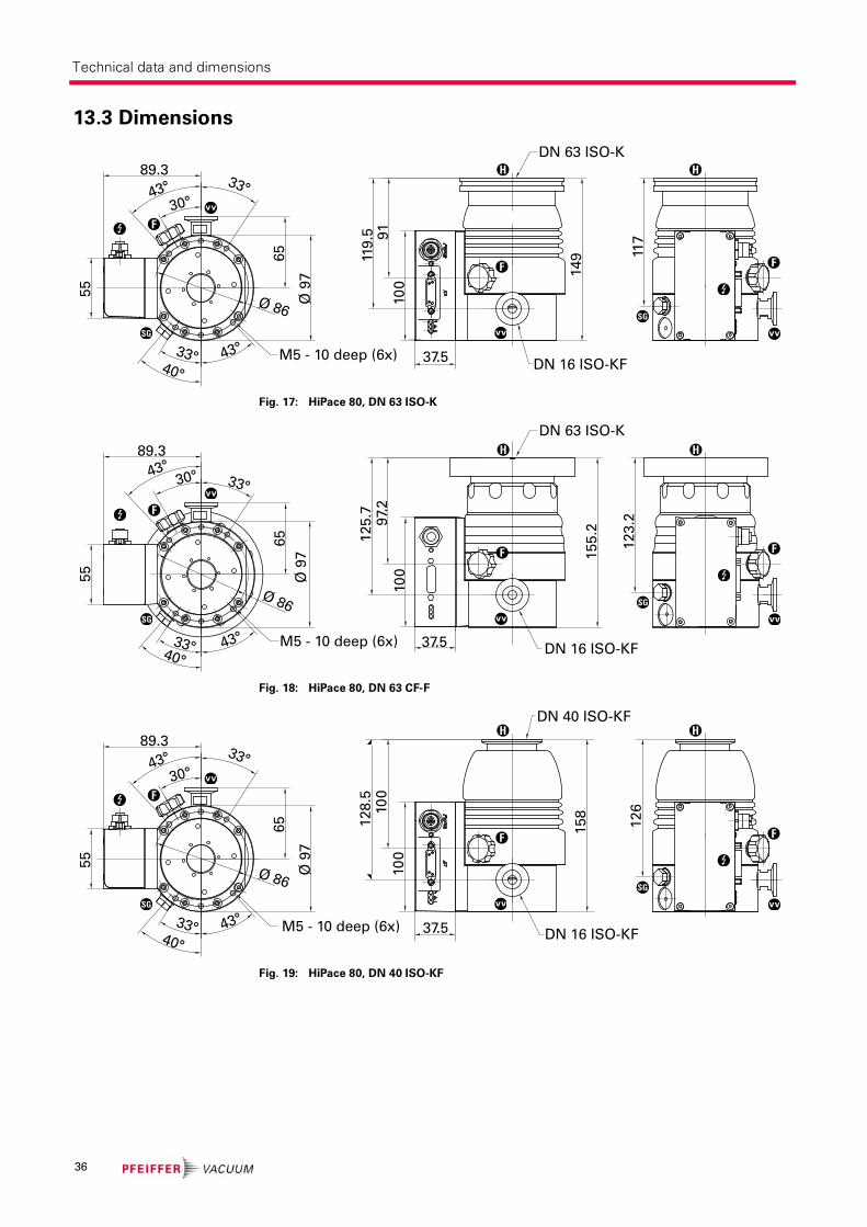
13.3 Dimensions
Fig. 17: HiPace 80, DN 63 ISO-K
Fig. 18: HiPace 80, DN 63 CF-F
Fig. 19: HiPace 80, DN 40 ISO-KF
89.3
30°
65
91
DN 63 ISO-K
DN 16 ISO-KF
14
9
37.5M5 - 10 deep (6x)
43° 33°
33° 43°
40°
Ø 86Ø
97
10
0
119
.5
117
55
F
F F
H H
SG
SG
DN 16 ISO-KF37.5
55
65
10
0
12
5.7
15
5.2
89.3
Ø 9
7
40°43°
30°43°
Ø 86
97.
2
33°
12
3.2
33°
DN 63 ISO-K
M5 - 10 deep (6x)
F
F F
H H
SG
SG
10
0
10
012
8.5
15
8
37.5 DN 16 ISO-KF
DN 40 ISO-KF
12
6
89.3
30°
65
M5 - 10 deep (6x)
43° 33°
33° 43°
40°
Ø 86
Ø 9
7
55
F
F F
H H
SG
SG
36
Declaration of conformity
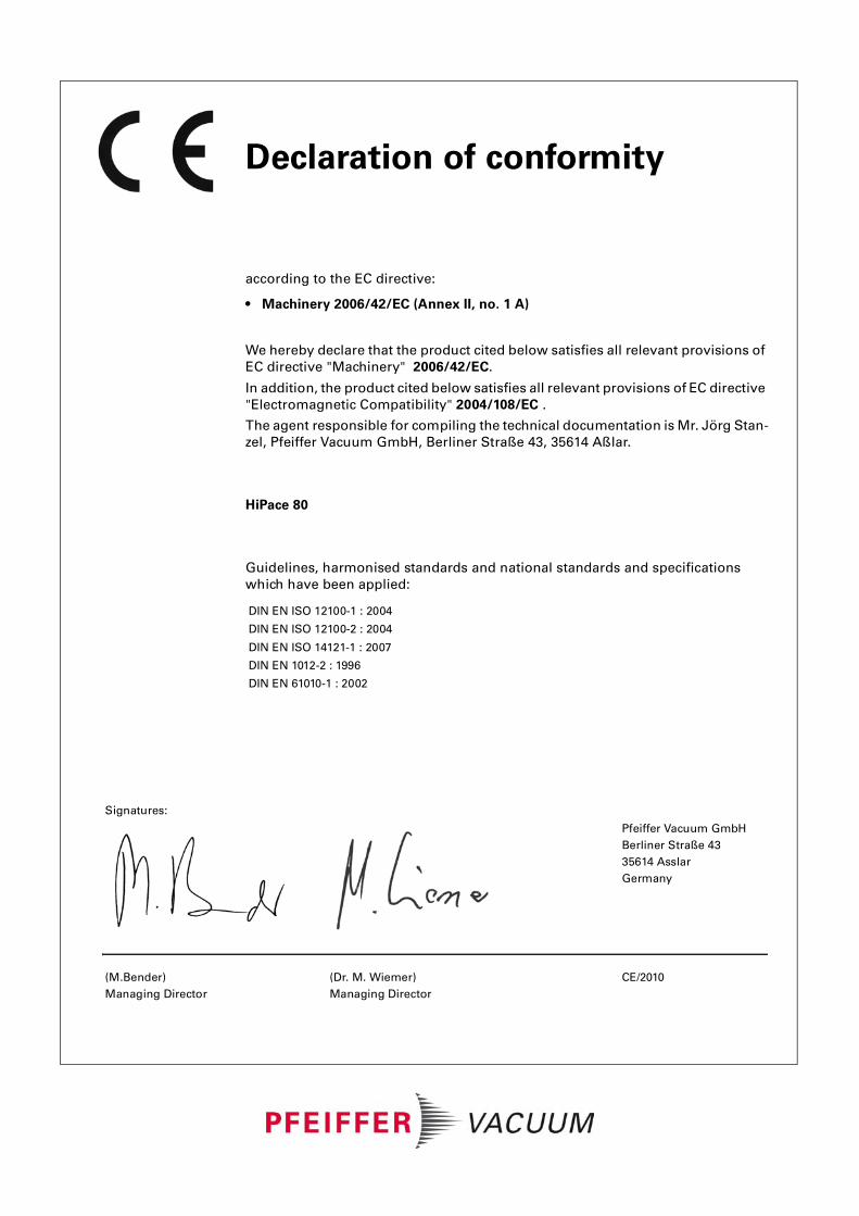
according to the EC directive:
• Machinery 2006/42/EC (Annex II, no. 1 A)
We hereby declare that the product cited below satisfies all relevant provisions of
EC directive "Machinery" 2006/42/EC.
In addition, the product cited below satisfies all relevant provisions of EC directive
"Electromagnetic Compatibility" 2004/108/EC .
The agent responsible for compiling the technical documentation is Mr. Jörg Stan-
zel, Pfeiffer Vacuum GmbH, Berliner Straße 43, 35614 Aßlar.
HiPace 80
Guidelines, harmonised standards and national standards and specifications
which have been applied:
DIN EN ISO 12100-1 : 2004
DIN EN ISO 12100-2 : 2004
DIN EN ISO 14121-1 : 2007
DIN EN 1012-2 : 1996
DIN EN 61010-1 : 2002
Signatures:
Pfeiffer Vacuum GmbH
Berliner Straße 43
35614 Asslar
Germany
(M.Bender)
Managing Director
(Dr. M. Wiemer)
Managing Director
CE/2010

Yo
pe
Ple
Lea
Cus
u are looking for a
rfect vacuum solution?
ase contact us:
Germany
Pfeiffer Vacuum GmbHHeadquartersTel.: +49 (0) 6441 [email protected]
Benelux
Pfeiffer Vacuum GmbHSales & Service BeneluxTel.: [email protected]
China
Pfeiffer Vacuum(Shanghai) Co., Ltd.Tel.: +86 21 3393 [email protected]
France
Pfeiffer Vacuum France SASTel.: +33 169 30 92 [email protected]
Great Britain
Pfeiffer Vacuum Ltd.Tel.: +44 1908 [email protected]
India
Pfeiffer Vacuum India Ltd.Tel.: +91 40 2775 [email protected]
Italy
Pfeiffer Vacuum Italia S.p.A.Tel.: +39 02 93 99 05 [email protected]
Korea
Pfeiffer Vacuum Korea Ltd.Tel.: +82 31 266 [email protected]
Austria
Pfeiffer Vacuum Austria GmbHTel.: +43 1 894 17 [email protected]
Sweden
Pfeiffer Vacuum Scandinavia ABTel.: +46 8 590 748 [email protected]
Switzerland
Pfeiffer Vacuum (Schweiz) AGTel.: +41 44 444 22 [email protected]
United States
Pfeiffer Vacuum Inc.Tel.: +1 603 578 [email protected]
Pfeiffer Vacuum stands for innovative and customvacuum solutions worldwide. For German engineering art,competent advice and reliable services.
Ever since the invention of the turbopump, we´vebeen setting standards in our industry. And this claimto leadership will continue to drive us in the future.
ding. Dependable.
tomer Friendly
www.pfeiffer-vacuum.net