Embed Size (px)
Citation preview

Louisiana State UniversityLSU Digital Commons
LSU Historical Dissertations and Theses Graduate School
1973
Petrology of the Norphlet and SmackoverFormations ( Jurassic), Clarke County, Mississippi.Calvin Lee BadonLouisiana State University and Agricultural & Mechanical College
Follow this and additional works at: https://digitalcommons.lsu.edu/gradschool_disstheses
This Dissertation is brought to you for free and open access by the Graduate School at LSU Digital Commons. It has been accepted for inclusion inLSU Historical Dissertations and Theses by an authorized administrator of LSU Digital Commons. For more information, please [email protected].
Recommended CitationBadon, Calvin Lee, "Petrology of the Norphlet and Smackover Formations ( Jurassic), Clarke County, Mississippi." (1973). LSUHistorical Dissertations and Theses. 2379.https://digitalcommons.lsu.edu/gradschool_disstheses/2379

INFORMATION TO USERS
This material was produced from a microfilm copy of the original document. While the most advanced technological means to photograph and reproduce this document have been used, the quality is heavily dependent upon the quality of the original submitted.
The following explanation of techniques is provided to help you understand markings or patterns which may appear on this reproduction.
1. The sign or "target" for pages apparently lacking from the document photographed is "Missing Page(s)". If it was possible to obtain the missing page(s) or section, they are spliced into the film along with adjacent pages. This may have necessitated cutting thru an image and duplicating adjacent pages to insure you complete continuity.
2. When an image on the film is obliterated with a large round black mark, it is an indication that the photographer suspected that the copy may have moved during exposure and thus cause a blurred image. You will find a good image of the page in the adjacent frame.
3. When a map, drawing or chart, etc., was part of the material being photographed the photographer followed a definite method in "sectioning" the material. It is customary to begin photoing at the upper left hand corner of a large sheet and to continue photoing from left to right in equal sections with a small overlap. If necessary, sectioning is continued again — beginning below the first row and continuing on until complete.
4. The majority of users indicate that the textual content is of greatest value, however, a somewhat higher quality reproduction could be made from "photographs" if essential to the understanding of the dissertation. Silver prints of "photographs" may be ordered at additional charge by writing the Order Department; giving the catalog number, title, author and specific pages you wish reproduced.
5. PLEASE NOTE: Some pages may have indistinct print. Filmed as received.
Xerox University Microfilms 300 North Zeeb Road Ann Arbor, Michigan 48106 -

73-27,821
BADON, Calvin Lee, 1938-PETROLOGY OF THE NORPHLET AND SMACKOVER FORMATIONS (JURASSIC), CLARKE COUNTY, MISSISSIPPI.
The Louisiana State University and Agricultural and Mechanical College, Ph.D., 1973 Geology
University Microfilms, A XEROX Company, Ann Arbor, Michig

PETROLOGY OF THE NORPHLET AND SMACKOVER FORMATIONS
(JURASSIC), CLARKE COUNTY, MISSISSIPPI
A Dissertation
Submitted to the Graduate Faculty of the Louisiana State University and
Agricultural and Mechanical College in partial fulfillment of the requirements for the degree of
Doctor of Philosophy
in
The Department of Geology
by Calvin Lee Badon
B.S., Southwestern Louisiana Institute,' 1958 M.S., University of Kansas, 1963
May, 1973

ACKNOWLEDGEMENTS
The writer is indebted to Dr. C. H. Moore who served
as committee chairman and supervised the preparation of the
manuscript. Acknowledgement is also due Dr. R. E. Ferrell,
Dr. D. H. Kupfer, Dr. C. 0. Durham, Jr., and Dr. W. A.
van den Bold for critically reviewing the manuscript and
making many helpful suggestions.
A sincere expression of gratitude is due the various
oil companies who kindly furnished the data necessary for
a study of this kind. In particular, the writer wishes to
thank the Shell Oil Company for providing much of the con
ventional cores and drill cuttings, and Getty Oil Company
for making maps and other materials available.
Financial support was provided by the Geology Depart
ment, Louisiana State University, throughout the author's
residency, and by a Geological Society of America Penrose
Research Grant.
ii

TABLE OF CONTENTS
Page
ACKNOWLEDGEMENTS ii
LIST OF TABLES vi
LIST OF FIGURES vii
LIST OF PLATES ix
ABSTRACT ". . x
INTRODUCTION 1
Purpose 2 Study Area 3 General Geology 5 Methods 12
NORPHLET FORMATION 18
Lower Member 18 Stratigraphic Relationships 18 Petrology 21 Black Shale Facies 21 Red Siltstone Facies 21
Upper Member 24 Stratigraphic Relationships 24 Petrology 26 Quartz Sandstone Facies 26
Depositional Environments of Norphlet Formation . 31
SMACKOVER FORMATION 40
Lower Member 41 Stratigraphic Relationships 41 Petrology of Southern Area 43 Laminated Dolomite Facies 44 Mottled Dolomite Facies 49 Laminated Micrite Facies 52 Fossiliferous Micrite Facies 53 Oncolitic Pellet Facies 54
iii

SMACKOVER FORMATION (CONTINUED) Page
Petrology of Northern Area 55 Exchange #1 - Bufkin 6-7 56 Harris %}/- Moore 10-12 - 56 Sun #1 - Board of Supervisors 57
Depositional Environments of Lower Member of Smackover 57
Upper Member 62 Stratigraphic Relationships .' 62 Petrology 68
Pelletoidal Micrite Facies 70 Superficial O&micrite Facies 72 Pelmicrite Facies 73 Oolite Facies 76 Oncolitic Superficial Oolite Facies 81 Oolite-Quartz Dolomite Facies 84
Dolomitization of Oolite-Quartz Dolomite Facies 92
Depositional Environments of Upper Member of Smackover Formation 98
Cementation of Oblite and Oncolitic Superficial Oolite Facies 104 Description and Distribution 107 Sequence and Origin of Cements 114
LOWER MEMBER BUCKNER FORMATION 125
Stratigraphic Relationships 125 Petrology 128 Depositional Environment of Lower Member of the
Buckner Formation 133
STRUCTURE AND DEPOSITIONAL HISTORY 137
Nature of Substratum 138 Structural Framework 139 Depositional History . . . . . 141
REFERENCES 152
APPENDIX A. Methods of Petrographic Analysis 160 Al. Procedures '. T"? . . '. '. '. . T~ 160 A2. Classification of Sandstones 162 A3. Classification of Carbonates 163 A4. Description of Allochems and Fossils. . . 167 A5. Description and Origin of Anhydrite . . . 174
APPENDIX B. Lithofacies - Well Control 181 Bl. Norphlet Formation, Lower Member 181 B2. Norphlet Formation, Upper Member 182 B3. Smackover Formation, Lower Member . . . . 183
iv

APPENDIX B. CCONTINUED) Page
B4. Smackover Formation, Upper Member. . . . 185 B5. Buckner Formation, Lower Member 190
APPENDIX C. Detailed Petrology of Quartz Sandstone
Facies, Norphlet Formation . '. !! '. '. T . 191
APPENDIX D. Isopach Values 195
VITA 197
v
LIST OF TABLES
Table Page
1. Location of conventional cores 14
2. Location of drill cutting samples . . . . . . . 16
3. Summary chart, petrology of upper member of Smackover Formation 99
vi

LIST OF FIGURES
Figure Page
1. Study area and location of Smackover Fields. . . 4
2. Chart showing nomenclature of Upper Jurassic rocks in Mississippi 8
3. Isopach Map of Lower Member of Norphlet
Formation 19
4. Photographs: Norphlet Formation 23
5. Isopach Map of Upper Member of Norphlet Formation 25
6. Photographs: Norphlet Formation 28 7. Schematic Summary of Paleodepositional Environ
ments, Norphlet Formation 39
8. Isopach Map of Lower Member of Smackover Formation 42
9. Reference Well, Lower Member of Smackover Formation 45
10. Photographs: Lower Member of Smackover Formation 48
11. Photographs: Lower Member of Smackover Formation 50
12. Schematic Summary of Paleodepositional Environments, Lower Member, Smackover Formation . . . . 63
13. Schematic cross-section of Upper Smackover Lithofacies 65
14. Isopach Map, Upper Member of Smackover Formation 67
15. Reference Well, Upper Member of Smackover Formation 69
16. Photographs: Pelletoidal Facies and Superficial Oomicrite Facies 71
vii

Figure Page
17. Photographs: Pelmicrite Facies 75
18. Photographs: Oolite Facies 78
19. Photographs: Oncolitic Superficial Oolite Facies. 83
20. Photographs: Oolite-Quartz Dolomite Facies. . . . 85
21. Photographs: Oolite-Quartz Dolomite Facies. . . . 88
22. Schematic Summary of Paleodepositional Environments, Upper Member, Smackover Formation 105
23. Photographs: Cement Types in Oolite and Oncolitic Superficial Oolite Facies 109
24. Outline of Progressive Cementation in Offshore Oolite and Superficial Oolite Facies 120
25. Reference Well, Lower Member of Buckner Formation 126
26. Photographs: Lower Member of Buckner Formation. . 128
27. Photographs: Lower Member of Buckner Formation. . 131
28. Classification of Carbonate Rocks 164
viii

LIST OF PLATES
Plate Pocket
I. Facies Relationships, Norphlet Formation
II. Facies Relationships, Lower Member of Smackover Formation
III. Stratigraphic Cross-section, Upper Member of Smackover Formation
IV. Isopach Map, Lower Member of Buckner Formation
V. Structure Map, Top of Smackover Formation
VI. Stratigraphic Cross-section of Norphlet -Smackover - Buckner Formations
ix

ABSTRACT
The Late Jurassic Norphlet and Smackover Formations
are entirely subsurface units in the conterminous United
States and are known only from data obtained from deep wells.
In Clarke County, Mississippi, the Norphlet Formation con
sists of nonfossiliferous terrigenous elastics 50 to 400
feet thick and the overlying Smackover Formation consists
of carbonate rocks 600 to 1000 feet thick. The petrologic
analysis of these subsurface units is based on conventional
cores and rotary drill cuttings which provide the basic data
for definition of the various lithofacies and reconstruction
of their depositional environments.
The Norphlet Formation which overlies the Louann evapo-
rites (Middle to Late Jurassic) includes three lithofacies,
a basal black shale facies, a middle red siltstone facies,
and an upper quartz sandstone facies. The black shale and
red siltstone facies represent supratidal to continental
deposits which prograded southward as the Louann evaporite
sea withdrew. The upper quartz sandstone facies represents
deposition along a low-lying desert coast and includes both
subaqueous shoreline sands and eolian sands.
The overlying Smackover Formation is subdivided into
upper and lower members, each of which contain several
x

carbonate lithofacies. The lower member facies are predomi
nantly carbonate mudstones and were deposited in a broad,
very restricted, shallow coastal plain in which carbonate
sediment production essentially kept pace with basin subsi
dence. The upper member lithofacies represent the first
evidence of widespread open marine conditions. From the
base of the upper member to the top, the carbonate facies
represents a classic regressive sequence with progressive
shoaling and continuous basinward progradation of environ
ments. The nodular anhydrite in the basal part of the
overlying Buckner Formation is the supratidal equivalent of
the Smackover marine carbonates. The oolite and super
ficial oolite facies which occur near the top of the Smack-
over Formation has primary depositional interparticle poro
sity and together they form the principal oil and gas reser
voirs in the Jurassic sequence. These initially porous
sediments were cemented during burial by several types of
calcite and dolomite cements in what is considered to be
sequentially distinct stages of cementation. These cement
types are described and the sequence of progressive cemen
tation is outlined.
The Louann-Werner evaporite sequence forms the sub
stratum upon which the Norphlet and Smackover rocks were
deposited. During deposition of the overlying strata, the
salt flowed in response to increasing overburden pressure
resulting in the formation of salt cored anticlines. The
earliest upward movement of the underlying salt mass appears
xi

to have occurred during deposition of the lower Smackover
(400-700 feet overburden) and during deposition of the
upper Smackover and lower Buckner (1000 to 1500 feet over
burden), the salt structures had their maximum upward
movement.
xii

INTRODUCTION
Rocks of Late Jurassic age comprise a thick sequence
of strata along the northern edge of the Gulf Coast Geosyn-
cline, extending from Florida on the East to Mexico on the
West. In the conterminous United States, these rocks are
entirely subsurface units and are known only from data ob
tained from geophysical well logs, rotary drill cuttings,
and conventional cores. The Late Jurassic rock-stratigraphic
units are, in ascending order, the Norphlet Formation, the
Smackover Formation, the Buckner Formation, and the Cotton
Valley Group. Of these, only the Norphlet, Smackover, and
the lower part of the Buckner Formation are included in this
study.
In Mississippi, Jurassic deposition was largely con
trolled by a local structural feature, the Interior
Mississippi Salt Basin. The basin is defined by the presence
of the Louann Salt (Middle to Late Jurassic, Kirkland and
Gerhard, 1971) which forms a continuous substratum upon
which the Late Jurassic rocks were deposited. During sub
sequent burial, the underlying salt flowed in response to
increased overburden pressure, forming diapiric salt domes
and salt-cored anticlines (Hughes, 1968). The paleoenviron-
ments of deposition and the possible effects of penecontem-
poraneous salt movement on these sedimentary environments
are fundamental, not only to reconstruction of the history
1
2
of the basin, but also to exploration for the deeply buried
oil and gas reserves contained in these rocks.
Purpose
Considerable controversy has centered around the
physical stratigraphy and depositional history of the Late
Jurassic rocks in the Gulf area. Much of the difficulty
arises from the necessity of using geophysical well logs
and drill cuttings for definition of rock-stratigraphic
units. As a result, facies relations between units which
require detailed petrologic information is seldom considered.
The analysis of specific depositional environments, based
on modern analogs, is generally not applied to subsurface
rocks because of the limited data available. Unfortunately,
the petroleum geologist is all too often forced into treating
the rock section as successive "layers" in a geochronologic
sequence, and log correlations as time-stratigraphic bound
aries .
The principal objectives of this study are to define
the various lithofacies within the Norphlet Formation,
Smackover Formation, and lower member of the Buckner Forma
tion, to establish the interrelationships between these
units and to reconstruct their depositional environments
in the framework of a logical depositional history based
on current sedimentological concepts. This work is the
first attempt to study systematically the petrogensis of
these rocks by using thin-sections made from drill cuttings

3
and conventional cores. Earlier published accounts of the
subsurface Jurassic have concentrated primarily on regional
stratigraphic problems based on examination of drill cut
tings in reflected light (Dinkins and Oxley, 1968).
A special section on structure and depositional history
is included in this study in order to determine the effect
of penecontemporaneous salt dome growth on deposition of the
late Jurassic rocks. To this end, isopach maps of the in
dividual members of each formation were constructed. How
ever, the structure is treated only to the extent that it
relates to the depositional history of the area. A more
complete analysis of the post-Jurassic structure would re
quire gravity and seismic data and is beyond the scope of
this study.
Study Area
The study area is situated on the northeast flank of
the Mississippi Salt Basin and covers an area 18 miles long
and 12 miles wide along the western edge of Clarke County,
Mississippi (Figure 1). This area was selected for study
because it includes the most prolific part of the Norphlet-
Smackover producing trend in the eastern Gulf region, and
as such, has the highest density of wells. In January,
1972, nine fields were producing from this sequence within
the study area, all of which were discovered during the
period 1967 to 1971.
The Goodwater, East Nancy, and Harmony Fields were

Watts Creek
o N. Shubuta
O
Q^ Goodwater
Clarke County^. "*""~ Wayne County
5
Miles
FIGURE 1. Study Area and Location of Smackover Field

5
selected for detailed study because they are thought to be
situated perpendicular to the Smackover shoreline. All of
the available conventional cores from these three fields
were used to establish the basic petrologic framework.
Cores and drill cuttings from adjacent areas were used
primarily to complete the stratigraphic sequence. Isopach
maps which reflect salt dome growth concurrent with deposi
tion were constructed to cover the entire study area.
General Geology
Tectonic Setting
Clarke County, Mississippi, is located along the north
east flank of the Mississippi Salt Basin, one of several
smaller depressions developed within the northern boundary
of the Gulf Coast Geosyncline. The basin was probably
initiated during Permian or Triassic time, as the oldest
deposits in the basin are reported to be Eagle Mills conti
nental elastics (Dinkins, 1968). Although these rocks have
not been dated in Mississippi, similar deposits in Southern
Arkansas were assigned a late Triassic age (Scott, et al.,
1961) based on plant remains. Clastic deposition was fol
lowed by deposition of the Werner-Louann evaporite sequence
(Middle Jurassic ?) which represents the first major incur
sion of marine waters into the basin. The up-dip limit of
this evaporite sequence to the north and the thinning of the
salt over the area of the Wiggins Anticline to the south
essentially defines the boundaries of the Mississippi Salt

6
Basin (Figure 1). Basin subsidence was accompanied by salt
flowage and minor faulting which represents the principle
structural modifications in the basin (Hughes, 1968). The
up-dip limit of the Louann Salt occurs near the northern
boundary of the study area and from here it is reported by
Hughes to form a thick wedge extending southwestward into
the center of the basin. Salt structures are thought to be
controlled by the primary thickness of the salt such that
across the study area the morphology of the salt structures
change from low relief swells on the north to high relief
anticlines on the South. The time of growth of these
structures and the degree to which they have affected sedi
mentation will be treated in the section Structure and De-
positional History.
Stratigraphy and Nomenclature
Considerable controversy has centered around the nomen
clature of Upper Jurassic rocks in Mississippi, both in the
literature and by petroleum geologists working in the area.
The formational nomenclature used in this study is considered
to follow the original usage proposed for the Norphlet
(Hazzard, et al., 1947), Smackover (Weeks, 1938), and Buck-
ner (Weeks, 1938) Formations in the subsurface of Union
County, Arkansas. The study area located on the north flank
of the geosyncline in Eastern Mississippi appears to be
generally along depositional strike with the type sections.
The sedimentary sequence therefore is sufficiently similar

7
in lithologic character to justify using the same nomencla
ture.
Two previous studies of the upper Jurassic stratigraphy
of Mississippi and Southwest Alabama are notable: Dickinson,
1962; and Dinkins, et al., 1968. The stratigraphic nomen
clature and formational boundaries used in this study differ
from the previous workers as shown in Figure 2.
Norphlet Formation
The Norphlet Formation as defined by Hazzard, Spooner,
and Blanpied (1947) at the subsurface type section in Union
County, Arkansas, consists of red and gray shales inter-
bedded with red and gray sandstones. As used here, the
Norphlet Formation includes all of the terrigenous elastics
overlying the Louann salt and underlying carbonate rocks of
the Smackover Formation. This usage is thought to be con
sistent with that proposed by Hazzard, Spooner, and Blanpied
to include strata overlying the Louann Salt and underlying
the Smackover Formation. The Norphlet Formation of this
study is used in the same sense as Dickinson, 1962 (Figure
2). However, the formational boundaries differ from that
used by Dinkins, et al., 1968. The Norphlet Formation of
these workers is probably equivalent only to the lower mem
ber of this study, and the upper member, as used here, was
referred to as lower Smackover sand by Dinkins, et al. 1968
CFigure 2).

•n
• n o H 3 P r+ H» O 3
V
P 3
cn a * J W
ts> •
2 ! O 9 CD
tL.y n
W H»
e O P r+
* * C i 3 CD H
H a>
o •D Hi O H a g >d p • d r+ H« O 3 H« 3
CD H
< H
c * p C/l
t i l w P to r+ CD •S 3
H> o
z o h»
>d 2 3 ^ H« U} (A H« t/J
to H-
>d >3 H-
M a> r+
*n o 4 3 P r t H-O 3
V
cn 3 P O * o < CD H
5" c 3 3
k CD 3 CD 4
5" c 0) 3 3
-
s* c 3 3 1
S CD 4 3 CD 4
c? 5 3 1
H CD f t
o
OJ f t H-O 3
2 O
3 3 J
H CD f t
>n O
1 OJ r t
O 3
Smackc
N o r p h l e t F o r m a t i o n
o c CD 4
s CD
& CD IS
£ •a CD 4
3 CD
1-CD 4
Smackover F o r m a t i o n
CD
s CD
& CD
3 a a H CD
cf
CD
>d CD
s CD
& CD 4
) ve r F o r m a t i o n
f C s CI *•
> > j
s ct > I-n h > i
C •d •a CD 4
s CD
i-CD 4
Smackover F o r m a t i o n
51" s CD 4
s CD .
§• CD ^
a >d
•a CD ^ s CD
& CD ^
Cd
o
3 CD
o
0) r t
o 3
H <
PJ
f t
o 3
S3 PJ
^ 3 CD W < H-l-1
H CD
o
(U r t
o 3
Buckner F o r m a t i o n
S" s CD •"S
s CD
& CD ^
€ >d CD 4
s CD ^ CD •3
•
O H» O J** H-3 0)
o
3
cn
a 3
£ H-3
0) 3 a o X fc1 CD ^ CD r t • P H
H
cn CO
t-5 3 C/l
!*J CD •d o hj f t

9
The formation appears to be present at least along
the northern edge of the Geosyncline from the panhandle of
Florida to East Texas. In Mississippi, the Norphlet Forma
tion extends beyond the up-dip limit of the Louann Salt to
unconformably overlie older Mesozoic and Paleozoic rocks.
The contact between the Louann and Norphlet Formations has
been described as unconformable (Hazzard, et al., 1947),
but physical evidence for unconformity in Mississippi is
lacking. In down-dip areas to the south, very little is
known of the Norphlet beds because of the greater depth of
burial and the diapiric nature of the underlying salt. In
these areas, wells are usually located over salt structures
which by their diapiric activity cause the salt mass to move
into a higher stratigraphic position above the level of the
younger strata. Therefore, wells drilled over salt struc
tures commonly bottom in diapiric salt, and the younger
strata which overlie the salt along the flanks of the
structure are missing from the stratigraphic section along
the crest. In the central and southern parts of the Missis
sippi Salt Basin, the Norphlet Formation has not been re
ported, but may be present in the interdomal areas.
Smackover Formation
The Smackover Formation was originally defined by
Weeks (1938) from Union County, Arkansas, and consists of
a lower cryptocrystalline limestone or "dense lime," and
an upper part which includes soft chalky limestone and

10
oolitic limestone. The Smackover Formation overlies the
Norphlet Formation conformably except over salt structures
where it rests upon diapiric salt. In up-dip areas where
the Norphlet is absent, the formation unconformably over
lies older rocks of Mesozoic and Paleozoic age.
The lower member commonly called the "brown dense
lime" is the most persistent lithologic unit in the Smack-
over and generally can be recognized throughout the northern
part of the Mississippi Salt Basin. In Jasper County,
Mississippi, at the western edge of the study area, the
lower unit is interbedded with gray terrigenous sandstones
of the Norphlet Formation. This has caused some workers to
consider the gray sandstones of the upper Norphlet as part
of the Smackover Formation (Dinkins, et al., 1968).
The upper member of the Smackover Formation shows a
greater diversity of lithologies and has been divided into
upper and middle members by Dickinson (1962, 1968). Two
extensive zones of detrital quartz sandstone are developed
in the upper part of the formation, one centered in Madison
County, Mississippi, and the other in Washington and Clarke
Counties, Alabama (Dinkins, et al., 1968). A thick sequence
of oolitic limestone which lies between these two clastic
wedges is developed in Clarke and Wayne Counties, Missis
sippi, and Choctaw County, Alabama.
Very little information has been published on the down-
dip lithology of the Smackover Formation. On the south
flank of the basin in Stone. County, Mississippi, the George
Vasen's Fee #1 penetrated 1,620 feet of carbonate rocks
which were assigned to the Smackover Formation (Applin and
Applin, 1953). To the east in Southwest Alabama, Dickinson
(1962) reported a down-dip Smackover facies consisting of
alternating beds of halite interbedded with anhydrite.
Buckner Formation
The term Buckner Formation was first applied by Weeks
(1938) to strata overlying the Smackover Formation in the
subsurface of Union County, Arkansas. These rocks were
described as consisting of an upper unit of red shale, a
middle unit of red shale with nodules of anhydrite, and a
basal unit consisting mainly of anhydrite with some stringers
of red shale and dolomite. These units were subsequently
included in the Haynesville Formation (Philpott and Hazzard,
1949) and the term "Buckner" was relegated to the lower
anhydrite part of the original formation. Following the
more recent work of Dickinson, 1968, and deBartolo, 1970,
the Buckner Formation, as used here, includes all of the
strata overlying the Smackover Formation and underlying the
Cotton Valley Group (Swain, 1944). The Buckner Formation
is divided into two informal members: an upper member that
is predominantly shale with variable amounts of limestone
and sandstone, and a lower member which is predominantly
anhydrite. Only the lower member which overlies and is
interbedded with the Smackover Formation is included in the
present work.

12
The lower member of the Buckner Formation appears to
be restricted generally to the north flank of the Missis
sippi Basin where it occurs as a band of variable width
that extends from southwest Alabama through central
Mississippi. A do\\rn-dip facies reported by Dinkins, et al. ,
(1968) was described as mainly dense limestone and shale.
Methods
The study materials are entirely from deep wells and
include conventional cores, rotary drill cuttings, and
geophysical well logs. The conventional cores are the most
important, as they provide the basic petrographic data for
definition^and description of the lithofacies. Where cores
are unavailable, thin sections made from rotary drill cut
tings were used to supplement the study. Geophysical logs
were used primarily for correlation purposes and secondarily
to aid in defining lithology over intervals from which only
drill cuttings were available. The use of subsurface
materials for petrologic work presents some problems not
normally encountered in the study of surface outcrops. For
this reason, tfte manner in which these were used is described
below. The procedures employed in the petrographic analysis
of the conventional cores and drill cuttings are found in
Appendix A.
Conventional Cores
Conventional cores refer to the sample of rock re
trieved by a hollow drilling bit which cuts and retains a
section of the rock penetrated. All of the available cores
from the Goodwater, East Nancy, and Harmony Fields were used
in the study as well as selected ones from adjacent areas.
A total of 29 cores from the Norphlet, Smackover, and Buck-
ner Formations were examined, and approximately 550 thin
sections were prepared for petrographic analysis. Table I
lists these cores according to formation, well name, loca
tion, and sample interval. On the reference sections (Figure
9, 15, and 25) and stratigraphic cross sections (in~pocket),
the cored interval is indicated by brackets on the left side
of the bore hole section.
Two problems were encountered which are inherent in
the use of conventional cores. The first is that the mea
sured depth of the core does not necessarily correspond to
the measured depth of the electric log over the same strati-
graphic interval. Consequently, the core must be shifted
vertically to coincide with the more correct log depth. In
most cases, a distinctive lithology in the core could be
matched with its resistivity characteristics on the electric
log. The amount of correction was occasionally measured in
tens of feet and is indicated on the stratigraphic cross-
sections. The second problem which imposes a more severe
limitation pertains to the physical condition of the core
itself. To facilitate handling, the cores are broken into

TABLE I CONVENTIONAL CORES
(Well Name)
NORPHLET FORMATION Shell #1 Johnston Getty #1 Masonite 18-8 Getty #1 Allen 20-7 Chevron #1 Hand "2" Exchange #1 Evans 35-1
(Location)
Goodwater Field E. Nancy Field E. Nancy Field Watts Creek Field N. Shubuta Field
(Sample-Interval (Measured Depth)
15602-15650 14301-14340 14300-14320 14377-14437 14862-14918
SMACKOVER FORMATION, LOWER MEMBER Shell #1 Johnston Getty #1 R.Williams 18-9 Getty #1 Masonite 18-8 Getty #1 Collins-Coleman
19-1 Getty #1 Allen 20-3 Getty #1 Allen 20-7 Chevron #1 Hand "2"
SMACKOVER FORMATION, UPPER
Shell #1 Johnston Shell #1 Ulmer Shell #1 Ruter Shell #1 Thomas Shell #3 Thomas Getty #1 Masonite 17-3 Getty #1 Masonite 18-8 Getty #1 Coleman 18-5 Getty #1 Allen 20-4 Getty #1 Allen 20-7 Getty #1 Masonite 20-70 Dunbar #A-1 M.Kirkland
29-1 Masonite #1 Masonite
20-6 Masbacher #1 Bd. of
Supv. 16-13 Exchange #1 Evans 35-1 Chevron #1 Hand "2" Harris #1 Moore 10-2 Shell #1-Evans 26-6
Goodwater Field E. Nancy Field E. Nancy Field E. Nancy Field
E. Nancy Field E. Nancy Field Watts Creek Field
MEMBER
Goodwater Field Goodwater Field Goodwater Field Goodwater Field Goodwater Field E. Nancy Field E. Nancy Field E. Nancy Field E. Nancy Field E. Nancy Field E. Nancy Field Harmony Field
. Harmony Field
Harmony Field
N. Shubuta Field Watts Creek Field WC/Sec.10, 3N-14E Pachuta Creek Field
BUCKNER FORMATION, LOWER MEMBER
15266-14035-14280-14150-
13995-14270-13834-
14623-14562-14623-14690-14630-13590-13509-14565-13580-13525-13561-12620-
12522-
13412-
14207-13372-11613-12828-
-15283 •14144 •14301 -14206
•14068 -14300 -13955
•14655 •14596 •14655 -14778 •14672 •13710 •13688 •14668 •13635 •13645 •13679 •12679
•12570
•12440
•14345 •13472 -11675 •12975
Shell #1 Johnston Getty #1 Masonite 14-4
Goodwater Field Nancy Field
14545-14565 13347-13456

pieces several inches in length and then slabbed into halves
or quarters and placed in boxes three to four feet long.
Because often times the cores were not properly marked
initially, the orientation and relative position of the
core pieces within each box usually cannot be determined.
In addition, individual beds which are thicker than the
length of the core pieces could not be measured.
Rotary Drill Cuttings
Drill cuttings are rock chips cut by a bit in the pro
cess of well drilling and are usually collected at intervals
of ten to twenty feet. The cuttings are normally contamina
ted from cavings farther up the hole and consequently litho-
logic descriptions based on cuttings are interpretive. How
ever, petrographic thin sections made from cuttings were
found to be useful for those intervals that were not cored
especially when used in conjunction with the geophysical well
logs. The drill cuttings are usually collected at ten or
twenty foot intervals and are considered to be a channel
sample. The procedure in this study was to select five to
ten representative chips from each sample which were imbedded
in plastic and standard petrographic thin sections were made.
The influence of uphole contamination is reduced signifi
cantly by a knowledge of the uphole lithologies and the
expected in-place lithology as deduced from the geophysical
logs. The rotary drill cuttings which were used are listed
in Table II. On the reference sections and cross-sections,

TABLE II
DRILL CUTTINGS EXAMINED
(Well Name)
Shell #1 Johnston
Shell #2 Johnston
Shell #3 Johnston
Shell #2 Thomas
Shell #3 Thomas
Shell #1 McCarty
Shell #1 Ulner
Shell #1 Ruter
Getty #1 Masonite 17-13
Getty #1 Masonite 14-14
Exchange #1 Evans 35-1
Chevron #1 Hand "2"
Getty #1 - Crook
Harris #1 Evans 4-4
Exchange #1 Bufkin 6-7
Harris #1 Moore 10-12
Sun #1 Board of Supervisor 16-13
(Location)
Goodwater Field
Goodwater Field
Goodwater Field
Goodwater Field
Goodwater Field
Goodwater Field
Goodwater Field
Goodwater Field
E. Nancy Field
Nancy Field
N. Shubuta Field
Watts Creek
(Stratigraphic Internal)
Buckner-Norphlet
Buckner-Norphlet
Buckner-Norphlet
Buckner-Norphlet
Buckner-Norphlet
Buckner-Norphlet
Buckner-Norphlet
Buckner-Norphlet
Buckner-Norphlet
Buckner,Norphlet
Norphlet
Buckner-Norphlet
Pachuta Creek Field Norphlet
WC/Sec. 4 1N-15E Buckner-Norphlet
WC/Sec. 6 2N-15E
WC/Sec.10 3N-14E
WC/Sec.16 3N-15E
Buckner Norphlet
Buckner-Norphlet
Buckner-Paleozoic
17
the intervals from which drill cuttings were examined are
shown by a heavy solid line to the right of the bore-hole
section.
Geophysical Well Logs
The well logs used in this study are the Dual-Induction-
Lateralog (DIL), the Compensated-Formation-Density Log (FDC),
and the Sidewall Neutron Porosity Log (SNP). The DIL log
was used primarily for correlation of strata between wells
and for determining upper and lower lithologic boundaries.
The FDC and SNP logs enabled lithologic determinations ac
cording to the cross,-plot method suggested by Schlumberger
Limited (1969). This interpretation is only an approxima
tion of gross lithology and was used solely as an aid in
selecting representative pieces from the drill cutting
samples. For mapping purposes, an effort was made to utilize
the geophysical logs from all the wells in the study area.
In some cases, the logs could not be made available for this
study, and these are indicated on the Structure Map (Plate
V) and in Appendix D as NA (not available).

NORPHLET FORMATION
The Norphlet Formation is a nonfossiliferous terri
genous clastic sequence composed of shales, siltstones,
and quartz sandstones. Within the study area, three litho-
facies can be defined: in ascending order these are a
black shale facies, a red siltstone facies, and a quartz
sandstone facies (Plate 1). These units are grouped into
two informal members based principally on texture, an
upper sandstone member and a lower member that consists of
the black shale and red siltstones. This textural sub
division is convenient for mapping purposes because where
drill cuttings and cores are unavailable, the members can
be readily distinguished on the basis of the DIL and FDC
logs. The upper member is particularly significant be
cause it produces oil in the East Nancy and Prairie Branch
Fields and carries shows of hydrocarbons in several other
areas.
Lower Member of the NorphletFormation
Stratigraphic Relationships
The lower member consists of two distinctly different
lithofacies, the basal black shale facies, and the over
lying red siltstone facies. The Isopach Map (Figure 3)
shows the thickness variations of the lower member within
the study area. The member thins across the Pachuta Creek
and Harmony Fields, but thickens to the south and reaches a
maximum value of 160 feet in the Watts Creek Field area.
18

FIGURE 3. Isopach Map, Lower Member of Norphlet Formation. CIsopach Values in Appendix D) Dashed line indicates extent of Black Shale Facies.

This maxima trends E-W along a line extending from Watts
Creek to East Nancy Field and possibly north of the Nancy
Field.
The basal black shale facies is probably present only
in the area of the Watts Creek, East Nancy, and Nancy Fields
(Figure 3) where it has an average thickness of 30 to 40
feet. This facies was identified solely on the basis of
drill cuttings (Appendix Bl) and where they were not avail
able, the presence or absence of the black shale facies
could not be determined. The overlying red siltstone facies
is present in every well which penetrated the section ex
cept the Sun #1 Board of Supervisors (WC/Sec. 16, 3N-15E)
situated on the upthrown side of the "A" fault (Figure 3).
In the Sun well, the Louann Salt is absent, and the well
penetrated 90 feet of black phyllitic shale at total depth.
The phyllitic shale is considered to be Paleozoic in age
because of the low rank metamorphic appearance of the rock
in thin sections. Between the phyllitic shale and the
Smackover carbonates is 170 feet (10940-11110) of material
that is completely unlixe the Norphlet rocks to the south.
In thin sections made from drill cuttings, these appear as
fragments of calcite, hematitic shales, and argillaceous
calcite. This unit is thought to be pre-Louann, and was
assigned to the Eagle Mills Formation by Dinkins, et al.,
(1968). On the downthrown side of the fault, the red silt-
stone is relatively thin, but thickens rapidly on the south
flank of the Harmony and Pachuta Creek structures.

Petrology
Black Shale Facies
The black shale facies was identified solely on the
basis of drill cuttings (Appendix Bl). During the initial
stages of the study, it was difficult to distinguish be
cause of contamination by gray shales from the uphole sec
tion. However, after the writer became more familiar with
the uphole lithologies, fragments of the basal facies- could
be separated on the basis of darker coloration, fissility,
and fresh appearance.
The black shale appears to be composed primarily of
argillaceous material and is considered to be laminated.*
The majority of the fragments, however, appear nonlaminated
which is thought to be due to unoriented fragments that are
cut roughly parallel to bedding. The black coloration is
probably due to carbonaceous material and where high concen
trations are found, the thin sections are almost opaque to
transmitted light. Silt size detritus is rare, but small
mica-flakes and dissiminated pyrite are fairly common. No
evidence of fossils was observed, but. it should be remem
bered that sampling was extremely meager.
Red Siltstone Facies
The overlying red siltstone facies was cored in only one
*(The bedding terms used here are from Bouma, 1962; lamination = < 0.5cm; fine bedded = 0.5-5.0cm; medium bedded = 5-20cm; thick bedded = > 20cm.)
22
well, the Shell #1 Johnston, Goodwater Field (Plate 1). Near
the upper part, the siltstone is laminated to fine bedded and
interbedded with lenses of red sandstone with scour features.
Below, the red siltstone grades into darker red silty mud-
stones and thin lenses of cross-laminated fine sandstones.
Also small, oblong, white to pink anhydrite nodules (Appendix
A4) are occasionally found in this zone.
This facies is composed primarily of angular silt-sized
quartz and coarse mica flakes (0.100-0.200mm), with a very
fine hematite matrix (Figure 4A). Laminations, where present,
consist of alternating laminae of predominantly hematite and
silt-sized quartz with interstitial hematite. The coarse
mica is usually found in the silt laminae and is oriented
roughly parallel to bedding. Anhydrite cement is also
present in the silt laminae where the grains are-packed
Cgrain supported), but it rarely makes up more than ten
percent of the interstitial material. In the mudstone units,
silt sized quartz and mica commonly occur "floating" in the
hematite matrix. The anhydrite nodules occur most frequently
in the mudstone beds and consist of small (0.050-0.200mm)
felty crystals, tightly packed with a subparallel fabric.
These nodules are thought to be early diagenetic; that is,
formed by displacive growth in soft sediment prior to lithi-
fication. However, the lack of stratification in the host
rock prevents definite determination of the time of growth
of these nodules. The interpretation is based primarily on
the similarity of the internal texture of the polycrystalline

23a
FIGURE 4. Photographs: Norphlet Formation
A. Red Siltstone Facies. Angular silt-size quartz and mica alternating with hematite laminae.
B. Red Sandstone Subfacies. Detrital dolomite (d) with zoned overgrowth and rounded quartz grains. The interstices are filled with hematitic detrital matrix.
C. Homogeneous Grey Sandstone Subfacies. Porous protoquartzite impregnated with dark resin which fills the interitices.
D. Homogeneous Grey Sandstone Subfacies. Large single crystal of dolomite cement (d) may be overgrowth on detrital dolomite nucleus.
E. Homogeneous Grey Sandstone Subfacies. Fine grained protoquartzite with interstitial anhydrite cement.
F. Close up of Figure 4-E showing quartz grains cemented by lath-shaped anhydrite crystals (a).

23b
0.1mm 0.1mm
0.1mm 0.1mm
0.1mm FIGURE 4 0.1mm

nodules with those found in the Smackover and Buckner Forma
tions where they are demonstratively early diagenetic.
Upper Member of the Norphlet Formation
Stratigraphic Relationships
Three subfacies can be distinguished within the upper
member of the Norphlet based on composition and sedimentary
structures: a lower red sandstone, a middle bedded grey
sandstone, and an upper homogeneous grey sandstone (Plate 1).
It should be noted, however, that the definition of these
units is based on five conventional cores (Appendix B2), each
representing only a part of the Norphlet sequence. There
fore, it is not known whether these three subfacies make up
the entire Upper Norphlet, or that additional sandstone sub
facies are present in the interval that was not cored.
Figure 5 is an Isopach Map of the upper member showing
the thickness variation across the study area. The values
shown with a plus sign, i.e. (+200) in Appendix D indicate
that the well bottomed in the upper member, and consequently
the isopach value represents a minimum thickness. The over
all variation in thickness is similar to the lower member
in that the unit is thin or absent across the Pachuta Creek
and Harmony Fields and thickens rapidly along the Watts
Creek, East Nancy, and Nancy Fields. In the north, the
upper member of the Norphlet Formation appears to be absent
from the Harmony and Pachuta Creek structures based pri
marily on the analysis of geophysical well logs. On the

FIGURE 5. Isopach Map, Upper Member of Norphlet Formation. (Isopach Values in Appendix D)

south side of these structures, the upper member shows much
more rapid changes in thickness than does the lower member,
and variations of one hundred feet in thickness over a
horizontal distance of several thousand feet are common.
Petrology
Quartz Sandstone Facies
At the base of the upper member, pink to red quartz
sandstones overlie and are interbedded with the red silt-
stones of the lower member. The red sandstones vary from
fine to medium-bedded (Figure 6D) with some zones of small
scale cross-stratification. In other beds, the rocks appear
more massive and commonly have irregular shale partings.
Large white anhydrite nodules are associated frequently
with these beds and are developed only where stratification
is lacking (Figure 6E).
In the middle unit, the bedded grey sandstone overlies
and is interbedded with the lower red sandstone unit and
except for coloration are very similar in appearance. The
grey sandstone beds are fine to medium-bedded with occa
sional small scale cross-stratification and scour features.
In the upper part of the unit, the beds are distinctive in
that they are laminated to fine bedded and steeply inclined
at 10 to 30 degrees to the borehole (Figure 6C). It cannot
be determined if these beds represent one large set of cross
strata or several smaller sets since the cores are broken
into smaller pieces for handling purposes. In addition, the
27
grey sandstone core is very friable and tends to crumble at
the exposed edges during normal handling. In the case of
the Exchange #1 Evans 35-1 (Plate 1) which was slabbed by
the writer, particular attention was given to this problem;
and it appears that from the top of the unit at 14,906 to
the base of the core at 14,918, the cross stratification
represents one continuous set, a minimum of 12 feet thick.
In this well, stratification was made more noticeable by
mud filtrate invasion along coarser grained laminae.
The third subfacies at the top of the upper member is
between 20 and 30 feet thick and consists of grey homo
geneous quartz sandstone. Stratification was not evident
in this unit and only infrequent horizontal shale partings
disrupt the homogeneous appearance. However, it is possible
that some of the core pieces were broken along bedding planes
and therefore went undetected. The upper contact between the
Norphlet sandstone and the overlying laminated dolomite of
the Smackover Formation was observed in cores from two wells
in East Nancy Field. In the Getty #1 Masonite 18-8 (Figure
6B), the contact is extremely sharp and the laminated dolo
mite is deflected around several pebbles or pinnacles of
Norphlet sandstone. In the Getty #1 Allen 20-7 (Figure 6A),
the laminated dolomite abuts against a very steep and irregu
lar upper surface of Norphlet sandstone. This core piece was
found out of place in a box containing core material from
several feet above the contact, but is nevertheless consi
dered to represent the contact between these two lithologies.

28a
FIGURE 6. Photographs: Norphlet Formation
A. Contact between Norphlet Quartz Sandstone and Smackover Dolomite (Getty #1-Allen 20-7). Irregular surface of homogeneous anhydrite cemented protoquartzite overlain by evenly laminated dolomite.
B. Contact between Norphlet and Smackover Formations (Getty #1 - Masonite 18-8). Overlying laminated dolomite is deflected around quartz "pebble."
C. Bedded Grey Sandstone Subfacies. Steeply inclined (25 degrees) laminae in medium protoquartzite.
D. Red Sandstone Subfacies. Horizontal evenly laminated fine feldspathic greywacke.
E. Red Sandstone Subfacies. Large white nodules of anhydrite in poorly bedded red feldspathic greywacke.

28b
METWC [f|]l!l|llll| llll
3J
niinqT _fi 5|
FIGURE 6

In thin-section, the upper member consists predominantly
of sand-sized quartz with variable amounts of feldspar, rock
fragments, and detrital matrix. These rocks are poorly cemen
ted and where the matrix content is low, the beds are friable
and have a high porosity. Although the three subfacies within
the upper member were defined initially on the basis of colora
tion and sedimentary structures, there are also significant
petrographic differences between each unit. In the petro-
graphic description of the individual subfacies, these dif
ferences are stressed in order to aid in the analysis of
depositional environments. A more detailed petrologic des
cription of the Upper Norphlet sandstone facies is included
in Appendix C.
Red Sandstone Subfacies
This unit consists primarily of fine sand-sized quartz
grains which are angular to subangular and poorly to modera
tely sorted. Feldspar is much more abundant than rock frag
ments and commonly make up as much as 15 percent of the grain
content. Detrital dolomite, in many cases indistinguishable
from dolomite cement, is a prominent accessory mineral in
this unit (Figure 4B). The dolomite usually has overgrowths
which give the grain a more euhedral shape than the associated
quartz grains. Detrital hematitic matrix fills between 30 to
50 percent of the interstitial pore space, therefore, the
rocks are classified as fine feldspathic greywacke. This
unit is distinguished from the overlying grey sandstone by

the presence of hematite, greater detrital matrix content,
and abundant detrital dolomite.
Bedded Grey Sandstone Subfacies
At the base of this unit, the rocks are similar to the
underlying red sandstone unit and are also classified as
fine feldspathic greywackes. The principal differences are
an absence of hematite and slightly less detrital matrix,
between 20 to 30 percent. However, in the upper part of
the bedded grey sandstone (steeply inclined strata, see
Plate I), the rocks exhibit considerable difference both in
composition and texture when compared to the base of the
unit. Quartz plus chert make up approximately 80 percent
of the grain content, and the grains are larger (medium to
coarse sandsized), better rounded (subrounded to rounded),
and better sorted (moderate to well sorted). Rock fragments
and feldspar are present in approximately equal amounts and
together seldom make up no more than 15 percent of the grain
content. Detrital matrix is virtually absent in these sands
and therefore the rocks are classified as either protoquart-
zites or subarkoses. Dolomite (Figure 4D) and anhydrite are
the major cement types, but these seldom fill more than 20
to 30 percent of the pore space. Because core data were not
available over the middle part of the unit (Plate I, between
base of unit in the Shell #1-Johnston and upper part of unit
in Exchange #1-Evans 35-1 and Getty #l-Masonite 18-8), the
bedded grey sandstone subfacies cannot be treated in terms

of a continuous vertical sequence.
Homogeneous Grey Sandstone Subfacies
These rocks are similar to the underlying bedded sand
stones except that rock fragments are usually more abundant
than feldspar, and consequently the rocks are classified as
medium protoquartzites (Figure 4C). Grain size is fairly
uniform throughout the unit except in the uppermost part
where grain size decreases to fine sand size. In this part
of the unit, anhydrite cement is much more abundant and the
rock is relatively well cemented (Figure 4E). At the top
of the unit in the Getty #1 Allen 20-7, eighty percent of
the void space was cemented by anhydrite (Figures 4E, 4F,
6A) and in the Getty #1 Masonite 18-8 (Figure 6B), anhy
drite fills 30 to 40 percent of the void space.
In the area to the north of Harmony Field, the Norphlet
sandstone was encountered in two wildcat wells (Exchange #1
Bufkin 6-7 and Harris #1 Moore 10-12), and appears to be
fine to medium protoquartzites with a high percentage of
anhydrite and dolomite cement. Dolomite fragments are
associated with the quartz sandstone fragments which prob
ably indicate that the Norphlet here consists of inter-
bedded dolomitic quartz sandstone and arenaceous dolomites.
Depositional Environments of the Norphlet Formation
The black shale facies would seem to represent deposi
tion under stagnant, low-energy conditions as evidenced by

32
the laminated, organic rich, fine-grained sediment. Un
fortunately, the depositional relationship of this facies
with the underlying Louann Formation cannot be determined
because of the lack of core data from this part of the sec
tion. Black carbonaceous shales have been reported from
some evaporite sequences (Peterson and Hite, 1969), and it
is possible that this facies is more properly part of the
underlying Louann Formation. The geometry of the shale
body (Figure 3) suggests settle-out deposition in a trough-
shaped depression, possibly developed during the terminal
phase of Louann evaporite deposition.
The red siltstone facies is thought to represent supra-
tidal mud-flat deposits which prograded southward as the
Louann evaporite sea withdrew. Deposition probably occurred
under arid conditions as indicated by the pervasive hema
tite (T.R. Walker, 1967) and development of early diagene-
tic anhydrite nodules. The nodules are considered to be
formed from interstitial pore fluids concentrated by evapo
ration in an arid supratidal environment similar to the
supratidal flats in the north-west corner of the Gulf of
California (Kinsman, 1968) . Evidence of desiccation in
this facies is lacking, but this may be due to the absence
of significant amounts of clay material. If the region
were arid, soil forming processes would be retarded and
the resulting product would be a clay-poor detritus derived
mainly by mechanical weathering. On the evidence from one
core (Plate I), the red siltstone facies coarsens upwards

and changes from predominantly hematitic mudstones to pre
dominantly hematitic siltstones with interbedded cross-
laminated fine sandstones. These upper beds are thought to
be the result of alternating periods of tidal current deposi
tion and slack-water deposition (Reineck and Wunderlich,1968)
and may represent the basal part of a transgressive sequence.
The sandstone facies of the upper member indicates a
rather abrupt influx of sand-sized detritus into the area.
In eastern Mississippi, the source area appears to have been
from the east as the sandstone content increases in this di
rection (Dickinson, 1962). However, some of the micaceous
rock fragments and the detrital dolomite may have been de
rived from land areas to the north where Carboniferous
phyllitic shales and lower Paleozoic dolomites were possibly
exposed at this time. The overall mineralogy of the sand
stone facies is fairly uniform and suggests a single prove
nance for the entire sandstone sequence. Consequently, the
development of the three distinct subfacies is the result
of changing conditions within the basin of deposition.
The red sandstone subfacies at the base of the upper
member is thought to represent a low tidal sand flat. This
unit reflects a continuation of the coarsening upward trend
observed in the red siltstone facies associated with an in
crease in sand contribution. Anhydrite nodules occur less
frequently, and hematite is less pervasive than in the
underlying red siltstone. The red fine-grained feldspathic
greywackes appear to be in part derived from reworking of

the upper part of the red siltstone facies.
The overlying grey sandstone unit indicates an increase
in current activity as bedding is well developed with scour
and cross-stratification features common. The absence of
hematite and the decrease in relative abundance of detrital
matrix is also thought to reflect more active traction cur
rents. If these rocks are considered to represent a contin
uous vertical section, then the sequence indicates a trans-
gressive cycle from supratidal mud-flat environments grading
upward into intertidal sand environments. Because these
beds lack any evidence of fossils, it is not known whether
normal marine conditions existed offshore or that evaporite
deposition (Louann evaporites) was continuous in the basin.
Similarly on the basis of one core (Plate I), it cannot be
definitely established that the increase in current energy
is associated with shoreline processes (intertidal) and not
fluvial processes. Tyrrell, 1973, (in press) suggested that
most of the upper member sandstone (referred to as "Denkman
Sandstone Member" by Tyrrell) was deposited under fluvial-
eolian environments. An intertidal origin is preferred for
the basal part of the bedded grey sandstone subfacies be
cause of the uniformity of grain size (fine sand-size) and
conspicuous decrease in degree of oxidation of the iron-
bearing grains and detrital matrix.
The stratigraphic relationship between the steeply in
clined protoquartzite sandstone in the upper part of the
bedded grey sandstone subfacies (Plate I) and the feldspathi

greywacke sandstone in the lower part of the subfacies cannot
be determined because cores were not available in the inter
val between the upper and lower parts. The protoquartzite
beds are laminated to fine bedded, steeply inclined (10 to
30 degrees) and consist of rounded, well-sorted sand essen
tially free of detrital matrix. These strata are thought
to represent eolian dune sands and are very similar to in
ferred Norphlet eolianite sandstones described by Tyrrell,
1973. Tyrrell studied more complete core sections in Rankin
County, Mississippi (80 miles west of the study area), and
he concluded that most of the Norphlet sandstone strata can
be characterized as large sets of steeply inclined lamina
tions which he interpreted as eolianite sandstones. Al
though only partial cores of steeply inclined strata were
available in the study area (Plate I, 12 feet in Exchange
#1-Evans, and 10 feet in Getty #l-Masonite), these are very
similar to the large sets of cross-strata described by
Tyrrell and are also thought to be eolian in origin.
The homogeneous grey sandstone at the top of the Nor
phlet Formation may have been formed during a minor trans
gression of the shoreline over the coastal dune sands.
This unit is 20 to 30 feet thick and consists of fine to
medium protoquartzite that is characterized by an apparent
lack of stratification. The homogeneity of the sand
stone is possibly the result of bioturbation, although
physical evidence of biological activity is lacking. As
the texture and composition of the rock is similar to the

underlying cross-stratified sandstone, it seems probable
that the homogeneous grey sandstone is in part derived by
reworking of the underlying eolian sand bodies. In East
Nancy Field, the upper surface of the homogeneous grey sand
stone appears to have been at least semi-lithified prior to
deposition of the overlying Smackover laminated dolomite beds
(Figure 6A,6B). Early lithification by evaporite cementation
could have occurred during a time of subaerial exposure and
concentration of near-surface brines by evaporation. The
relationship of the overlying basal Smackover carbonate
beds (discussed in "Depositional Environments of the Lower
Member of the Smackover Formation") seem to indicate that
the Norphlet sandstone may have had some relief during the
initial phase of carbonate deposition. The laminated dolo
mite overlying the homogeneous grey sandstone in East Nancy
Field is inferred to represent deposition in a protected,
shallow water area. To the south in Goodwater Field, the
Norphlet sandstone is overlain by dolomitic silty micrite
Cprobably nonlaminated) which is thought to be the offshore
equivalent of the laminated dolomite beds. It is possible
that during the initial phase of carbonate deposition
CSmackover) linear ridges of Norphlet sandstone separated
the low energy shallow water deposits (laminated dolomite)
from the offshore deposits (nonlaminated micrite) .
The interpretation of depositional environments dis
cussed above is based on "spotty" core data. As the con
ventional cores were taken from wells several miles apart,
37
and each core represents only a small part of the vertical
rock section, reconstruction of a composite section is
hazardous. For example, it cannot be determined if the
inferred intertidal sands (Shell #l-Johnston, Goodwater
Field) extend as far north as East Nancy Field. Similarly,
it is not known if the inferred eolian sands in East Nancy
and North Shubuta Fields are continuous into Goodwater Field.
Nevertheless, the conventional cores and supplementary drill
cutting data indicate an overall pattern of sedimentation
for the Norphlet Formation which can be summarized as
follows. The withdrawal of the Louann evaporite sea was
probably concomitant with an increase in detrital influx
into this part of the basin. As the sea withdrew, the basal
Norphlet beds (red mudstones and siltstones) prograded over
the updip Louann evaporite beds. Arid conditions prevailed
during this time as evidenced by the occurrence of pene-
contemporaneous evaporite minerals and oxidation of iron-
bearing minerals in the red beds. It is possible that
during this time evaporite deposition was continuous in the
deeper parts of the basin. In the upper member of the Nor
phlet Formation, the presence of eolian dune sands may re
present a continuation of arid conditions. Tyrrell (1973)
reported the widespread occurrence of eolianites and sug
gested that desert conditions were established on the
northern and western margins of the basin during deposition
of the upper member sandstones. It is not known whether
carbonate sedimentation (Smackover) was beginning in the

deeper parts of basin at this time or that evaporite sedi
mentation (Louann) was continuous.
There appears to have been several periods of minor
transgressions in the overall regressive Norphlet sequence.
It is thought that during deposition of the upper member
sandstones, this area was situated along a low-lying desert
coast such that minor fluctuations in the rate of subsidence
or rate of detrital influx resulted in transgressions of the
shoreline. Figure 7 is a schematic summary of the inferred
facies relationships and sequential changes in depositional
environments of the Norphlet Formation. At the base of the
Norphlet (Figure 7A) , the black shale facies is shown as
part of the Louann evaporites. The overlying red siltstone
facies is considered to be a supratidal regressive deposit
that prograded southward as the Louann Sea withdrew from
the area. In Figure 7B, the upper member red sandstone and
lower part of the bedded grey sandstone are shown as trans-
gressive deposits onlapping the underlying red siltstones.
A regressive phase is shown in Figure 7C, with eolian de
posits prograding southward. Figure 7D illustrates the
terminal phase of Norphlet deposition during a minor trans
gression of the shoreline. The change from a regressive
shoreline (Figure 7C) to a transgressive shoreline (Figure
7D) may have been due to a rapid decrease in the amount of
detritus available. As basin subsidence continued and the
amount of terrigenous detritus diminished, carbonate sedi
mentation began in this part of the basin.

B
Bedded Grey Sandstone
D Homogeneous Grey Sandstone
FIGURE 7. Schematic Cross-Section of Paleodepositional Environments, Norphlet Formation. Explanation in Text,
SMACKOVER FORMATION
The Smackover Formation is present throughout the study
area and ranges in thickness from 250 feet in the northeast
to greater than 900 feet in the southern part of the area.
The formation is subdivided into upper and lower members,
each of which contains several carbonate lithofacies. The
lower member is composed predominantly of micrite* and very
finely crystalline dolomite with minor amounts of spongy on-
colites, intraclasts, and pellets. The upper member is in
rather sharp contrast to the lower member and consists pri
marily of well-winnowed accretionary allochems and allochem-
bearing micrites.
The petrology of the upper and lower members is based
on the analysis of conventional cores and drill cuttings from
the Goodwater, East Nancy, and Harmony Fields (Figure 1).
For regional mapping purposes away from these areas, the
electric log characteristics were usually distinct enough
to determine upper and lower contacts without the aid of
drill cuttings. The lower member has a typically high resis
tivity (as measured by the Deep-Induction curve), usually in
excess of 100 ohms m2m, whereas the resistivity of the upper
member seldom exceeds 50 ohms m^m over much of the section
(Plate VI). The Isopach Maps of the upper and lower members
(Figure 8 and 14) are based mainly on the DIL log "picks."
*The carbonate classification, carbonate grain types, and general petrographic conventions are in Appendix A.
40

Lower Member
Stratigraphic Relationships
The lower member of the Smackover Formation generally
onlaps progressively older rocks toward the North (Plate V).
In the southern part of the area, the lower member rests on
grey sandstone of the Upper Norphlet. In the vicinity of
Pachuta Creek and Harmony Fields, it overlies Lower Norphlet
red siltstones, and to the north of Fault "A" in the Sun #1
Board of Supervisors, undifferentiated Smackover carbonates
overlie the Eagle Mills Formation.
The lower member can be identified usually by drill
cutting samples and geophysical logs except in the region
to the north of the "A" Fault where the Smackover Formation
is undifferentiated. However, cores were available only in
the southern area (Table 1), and most of these are in the
East Nancy Field. North of Harmony Field, drill cuttings
were examined from three wells: the Exchange #1 Bufkin 6-7,
the Harris #1 Moore 10-12, and the Sun #1 Board of Super
visors .
As shown on Figure 8, the lower member generally thickens
in a southwest direction from 300 feet in the northeast to
approximately 600 feet in the southwest part of the study
area. It is thin across the Harmony Field, but thickens
to the south along the south side of the Pachuta Creek and
Harmony Fields. In the southern part of the study area, the
thickness relationships are more variable, and definite
trends cannot be established. In the East Nancy Field, the

42
T
9
N
T
1
N
T
1
N
T
10
N
R 14 I
•
-
•
•
-
4? C
• "V •
•
-
-
•
•
/ * m i # M
•
-
•
•
• •
\
WESTNANJbr \ \ V
\
-
-
•
•
toon
' '
/
/ °
V **
\_ * \ '*
$ \
•
>«EAN£^
•
R U B
•
V •
\
)
•
•
f
• X
• \ * \*
* 1 *
* 1 * • J
\ °
•
•
* * 1
-
•
, •
•
V >
\
- J
•
PWHUTA
* \m
• \« • Ik
4 *
O
•y
•
" \
«
1 nil
B U B
<&'
Cliufk
1 •
*
) •
\ "
^
x\ JjOODHBTER
•
\ • -
' J \ Sup # £ • / .
n
•
•
HARMONY • •
• •
*-*"*~*
-4ocy
*^>
>,
^ X ^ A S T h
"*""v\
V) IJ •
\5X •
•
•
o
* 0
•
o
'
AhCT "
V-S**-
R
y •
X -
^ ^
•
-
-
-
-
•
\. *
' •
— r
1 *
• I E /
•
-
•
* ' / X
•
•
•
-300'
-
•
^>3E
r k. \ -
/ NORTH r SHUBUTA
•7
• .
•
„ a
N
-
-
•
T
N
•
-
•
o*—1
CRBB
^ 5 ;
^
'
CLAKKE COUNTY HISS. Iiopachottt Uap
Lowsr Smackover Ddm3antmr \}97\
MifpnKMon bys Cvwn L Bodon U U " ' ' — •• — ' '
^m sjmnB raumyiiuuu
• 01VW iff N>»dhJt
:&«a-5cr o r - i aopo R » w B a w
FIGURE 8. Isopach Map, Lower Member of the Smackover Formation. (Isopach Values in Appendix D)

member thickens across the structure, and a possible thin
area is shown on the northeast flank. In the Goodwater
Field, the lower member appears to thicken northwestward
across the structure, and a similar thin area is shown to
the east.
Petrology of the Southern Area
Five lithofacies were distinguished in cores from the
southern area: laminated dolomite facies, mottled dolomite
facies, laminated micrite facies, fossiliferous micrite
facies, and oncolitic pellet facies (Plate II). The lami
nated dolomite facies which overlies the Norphlet Formation
at the base of the sequence is the only facies that can be
correlated between wells. The remaining four facies con
stitute the main body of the member and these appear to be
discontinuous laterally between wells. Individual litho
facies are not represented by a single unit, but rather
each facies is comprised of several units which are mutually
interbedded with other lithofacies units. In any one core
section (50 to 100 feet in length), each lithofacies may
occur several times such that the entire section can be
characterized as alternating lithologies. Evidently en
vironmental conditions were fluctuating continuously with the
result that individual facies repeatedly shifted laterally
resulting in rapid changes in the vertical sequence in any
one well. The repetition of lithofacies appears to follow a
specific order; for example, units of the mottled dolomite

facies are always underlain and overlain by units of the
laminated micrite facies, and are never found adjacent to
units of the fossiliferous micrite facies. The relative
positions of these facies in the section is critical to the
interpretation of the depositional environments. The refer
ence section for the lower member (Figure 9) illustrates
the stratigraphic relationships of the three most frequently
occurring facies: the mottled dolomite facies, the lami
nated micrite facies, and the fossiliferous micrite facies.
Laminated Dolomite Facies
This facies occurs only at the base of the lower member
and was cored in two wells, the Getty #1 Allen 20-7 (Plate
II) and the Getty #1 Masonite 18-8. In these two wells,
which are approximately 4500 feet apart, the lithology was
found to be identical and therefore the facies probably has
lateral continuity. In addition, this unit is the only faci
in the lower member that could be identified in the drill
cutting samples and was recognized in samples from the East
Nancy, Nancy, and Watts Creek Fields (Appendix B). The
facies ranges from 30 to 50 feet in thickness and consists
almost entirely of uniformly laminated dolomite (Figures 6A,
10A). In the conventional core from the Getty #1 Masonite
18-8, the core is entirely laminated dolomite from the top
of the Norphlet sandstone to the top of the core interval.
However, in the core from the Getty #1 Allen 20-7, the
interval is entirely dolomite except for the top three feet

CORED SECTION
14050-
14060-
14070-
.14080-
14090-
REFERENCE SECTION Lower Member Smackover Formation
GETTY-#1 -R. WILLIAMS 18-9(EAST NANCY FIELD)
LAMINATED MICRITE FACIES Section 18,1N-15E
Laminated microstvlolitic raicritc with occasional thin beds of micrite; micrite beds contain large lenticular anhydrite
LAMINATED MICRITE FACIES
Laminated microstvlolitic nicritc
DISTURBED DOLOMITE FACIES Massive, burrowed dolomite; silty verv fine to finely xln. dolomite
Irregular fine bedded dolomite very finely xln. dolomite
LAMINATED MICRITE FACIES
Laminated microstvlolitic micrite with rare thin beds of micrite
DISTURBED DOLOMITE FACIES Irregular mod. bedded dolomite; silty very finely xln. dolomite
LAMINATED MICRITE FACIES
DISTURBED DOLOMITE FACIES Irregular fine bedded dolomite; anhydrite nodule c las t s in very
incly xln. dolomite
LAMINATED MICRITE FACIES
'DISTURBED DOLOMITE FACIES
h'inc to irregular hedtlcd dolomite; very finely xln. dolomite
Laminated microstylol i t ic micrite
MasMvc to irregular med. hedded dolomite; very finely xln. dolomite
OIL LOG LATEROLOG
CURVE
LAMINATED MICRITE FACIES
LAMINATED MICRITE FACIES DISTURBED DOLOMITE FACIES LAMINATED MICRITE FACIES
DISTURBED DOLOMITE FACIES
LAMINATED MICRITE FACIES
FOSSILIFEROUS MICRITE FACIES

14090-
14100-
14120-
14130-
14110-
m ¥+£
14140-
Massivc to irregular mod. hcddcd dolomite; verv flnclv xln. dolomite
.{A ' -14, LAMINATED MICtlTE FACIES
Laminated mlcrosty lo l i t ic n icr i tc with rare thin beds of micrite
as o s W f f « « ££ a EE
« m?. a
SKS
a KS5i 1 . 1 ' i ' i i L 3 as E 2 %* £ ^ a o S 53 ii i' i I
aa 1 2 0
s £ i S 1
E P£i
RHrPf?
FOSSNJFEROUS MICRITE FACIES Massive burrowed micrite with large sparse intraclasts
Irregular med. hcddcd burrowed intraclast-bcaring nicritc Key to
Dual Induction Log
(Data sources, curves, and scale)
Massive micrite with large packed intraclasts
EXPLANATION
Resistivity ohms mVm
10 100 2000
Conventional Core^—•
Massive irregular mcd. hcddcd burrowed micrite; 1-21 foss i l fragments
DEEP INDUCTION CURVE LATER0L0G CURVE
Drill cuttings
MHO-
\ Depth from derrick floor
Irregular fine to med. bedded burrowed pcl letoidal micrite; < 11 foss i l fragments
LITHOFACIES
DISTURBED DOLOMITE FACIES
LAMINATED MICRITE FACIES
FOSSILIFEROUS MICRITE FACIES
LITHOLOGY
7 — 7
2±E ] Laminated Dolomite ,'4 HaSsive but rowed micrite with large sparse intraclasts S
Erx
Irregularly Bedded Dolomite
Micrite
i V f
ra^ O
Fossils
Burrowing
Spongy Oncolite
passive dolomitic micrite; large irregular fragments of micrite matrix - possible solution breccia, carroded lenticular anhydrite
m Pelmicrile £58»e Composite Grains T O O r\rt r
?- i—c Microslylolilic laminaled Micrite 3 a a Intraclasts g a r
Solution Breccia ts cm. W n « i l
Anhydrite Intraclasts
FIGURE 9. Reference Well , Lower Member of Smackover Formation

of the core which is only partially dolomitic. In this part
of the core interval (Plate II), a small 5cm thick bed of
nonlaminated micrite separates underlying laminated dolo
mite from overlying laminated micrite containing only a few
scattered rhombs of dolomite. This small bed of nonlamina
ted micrite contains well developed fenestral or "birdseye"
structures which are filled with dolomite and anhydrite.
The dolomite laminae consists primarily of small tightly
packed subhedral dolomite rhombs, 0.030 to 0.060mm in size.
There is no consistent size variation between dolomite crys
tals in alternating laminae--a condition frequently cited in
the description of laminated dolomite rocks (R. D. Perkins,
1963; Carozzi and Textoris, 1967). The laminated appearance
results from microcrystalline granules of pyrite and brown
carbonaceous material which are concentrated in thin seams
which separate laminae. Microstylolites appear to be pres
ent between laminae and are probably responsible for the con
centration of the insoluble pyrite and carbonaceous material
(Figure 11A). Silt-size detrital quartz is rare even at the
base of the unit where laminated dolomite is in contact with
the upper Norphlet sandstone. However, large mica flakes
(0.100 to 0.150mm in length) were relatively abundant at
the base of the unit. In thin section, the basal contact
is extremely sharp, and no sand or silt-sized quartz was
found in the overlying dolomite. The only exception to this
is in the Goodwater Field where the basal Smackover rocks
consists of silty, dolomitic micrite rather than the laminated

dolomite. Laminations were not observed in cuttings from
this area, although they are normally difficult to detect
in the unoriented drill cutting fragments.
The environmental interpretation of the laminated dolo
mite facies is deferred until the later section entitled
"Depositional Environments of the Lower Member of the Smack-
over Formation." However, central to the question of de
positional environment is whether or not the laminae of the
laminated dolomite facies were formed through the binding
action of algae. As algal filaments are seldom preserved
in ancient dolomite rocks, the determination of algal
binding of sediment is usually based upon associated sedi
mentary features. Where algal mats occur in the intertidal
and supratidal environments, the criteria for recognition
are rather well established and include stromstolite (un
dulating) features, desiccation features, and algal clasts
(Friedman, 1969). Subtidal algal mats by contrast are less
distinctive primarily because of the absence of exposure
features such as subaerial desiccation and erosion surfaces.
Subaqueous shrinkage (syneresis) and erosion surfaces are
presumed to be much less frequent in the subtidal environ
ment. However, Geblein (1969) studied modern Bahaman sub
tidal mats and reports that small scale truncations and
algal clasts (flakes or chips) which are ripped up from the
more cohesive subtidal mats are typical features. In the
case of the laminated dolomite facies of the lower member
of the Smackover Formation, there is no evidence to suggest a

FIGURE 10. Photographs: Lower Member of Smackover Formation
A. Laminated Dolomite Facies. Parallel laminated finely crystalline dolomite.
B. Mottled Dolomite Facies. Massive, very finely crystalline dolomite with random dark anhydrite laths (poikiloblastic). Small allochems replaced by anhydrite (white).
C. Laminated Micrite Facies. Irregularly laminated micrite and interbedded nonlaminated micrite with probable compaction fractures filled with anhydrite.
D. Laminated Micrite Facies. Thick unit of wavy bedded micrite. Large lenticular anhydrite crystals concentrated in lighter colored micrite beds.
E. Fossiliferous Micrite Facies. Massive dark micrite with large sparse intraclasts. Spongy oncolite in center right.
F. Oncolitic Pellet Facies. Massive dark pelmicrite with sparse spongy oncolites.

48b
I METRIC l l | l i l l | l i l l | l l l l | l l l l | l l l | | l l ! l | | | | | l l | | |
II 2l 31 4l 5
FIGURE 10

supratidal or intertidal algal origin for the laminae. Simi
larly, the absence of algal clasts or discernable small-scale
truncation of laminae throughout the 30 to 40 feet of contin
uous laminated dolomite tends to preclude the possibility of
a subtidal algal mat origin for the laminae. In Figure 6A,
the laminations can be seen "abutting" against the irregular
Norphlet surface and is not "encrusting" as would be expected
if the laminae represent successive algal mats. It there
fore appears likely that the parallel laminations of the
laminated dolomite facies result from physical processes in
which settleout deposition (gravity) of fine grained sediment
occurred under restricted low energy conditions. The uniform
texture of the dolomite also favors a physical origin because
algal laminated dolomite commonly exhibit variation in size of
the dolomite crystal between alternating laminae (R.D.Perkins,
1963; Carozzi and Textoris, 1967). It is however recognized
that enlargement recrystallization of the dolomite could obli
terate any evidence of an earlier dolomite textural variation.
Mottled Dolomite Facies
The mottled dolomite facies occurs in units which are
usually less than ten feet thick and in vertical section, the
units of the mottled dolomite facies are always adjacent to
units of the laminated micrite facies. The beds range from
poorly laminated to massive, but most commonly have a wavy
or mottled appearance (Figure 10B). These beds frequently
have traces of hydrocarbons, and lower Smackover production

FIGURE 11. Photographs: Lower Member of Smackover Formation
A. Laminated Dolomite Facies. Finely crystalline subhedral dolomite with horizontal microstylo-lites.
B. Mottled Dolomite Facies. Very finely crystalline dolomite with allochem replaced by large clear crystals of dolomite.
C. Laminated Micrite Facies. Discontinuous alternating laminae of micrite (dark) and microspar (light).
D. Mottled Dolomite Facies. -Large composite grains (quiet water oolites) and preferentially dolo-mitized matrix.
E. Laminated Micrite Facies. Small spindle shaped, lenticular anhydrite crystals in laminated micrite.
F. Fossiliferous Micrite Facies. Large intraclast with lenticular anhydrite crystals, probably derived from the laminated micrite facies.

1.0 mm 0.1mm
1.0 mm 1.0 mm
0.1mm FIGURE 11 1.0 mm

in the area is probably from this facies.
The individual dolomite crystals are smaller and more
loosely packed than those in the laminated dolomite beds,
resulting in a higher porosity. The crystals are usually
euhedral and very uniform in size, between 0.010 and 0.015mm
in diameter (very finely crystalline). Allochems are common,
and where they occur "floating" in the dolomite matrix, they
are almost always preferentially altered to dolomite, anhy
drite, or single crystals of calcite (Figure 11B). The
composition, texture, and diagenetic character of this facies
is identical with beds found at the top of the Upper Smackover
and in the Buckner Formation. Because of this similarity, the
diagenetic character and environmental implications are dis
cussed more fully in the later section. At the base of one
of the dolomite units (in the Getty #1 Collins-Coleman well,
Plate II), the allochems occur in a packed or grain-supported
fabric with finely crystalline dolomite filling the inter
stices. In this bed, the allochems are not replaced, and
consist primarily of composite grains whereas the original
matrix is almost completely replaced by dolomite (Figure 11D).
The allochems are similar to the "quiet water oolites" des
cribed by T. Freeman (1962), from the Laguna Madre in Texas,
and the high matrix content is suggestive of deposition under
quiet water conditions. In one bed (the Getty #1 R. Williams
well, Figure 9), small nodules of anhydrite are scattered
throughout the unit. These consist of interlocking, felty
anhydrite crystals similar to those described from the Norphlet

52
Formation. Several of the nodules appear to be micrite-
coated, and these might be clasts of early diagenetic anhy
drite.
Laminated Micrite Facies
This facies is the most frequently occurring and was
present in all five wells in which the upper and middle
parts of the member were cored (Appendix B). In vertical
sequence, the laminated micrite is adjacent to beds of the
mottled dolomite facies and the fossiliferous micrite facies.
The laminations are seldom continuous across the width of the
core (3 to 4 inches) and are much more irregular (Figure
IOC) than those described from the laminated dolomite facies
(compare Figures 10A and IOC). The laminated sequence is
frequently interrupted by small beds of nonlaminated micrite
(Figure 10D) which occasionally contain large crystals of
lenticular anhydrite.
Lenticular anhydrite is restricted essentially to
this facies (see "Description and Origin of Anhydrite,"
Appendix A4). In the laminated micrite facies, the anhydrite
crystals occur as randomly oriented single crystals which
exhibit a characteristic lenticular or discoid shape. Two
crystal sizes appear to be typical: in the nonlaminated
micrite beds (Figure 10D), they are usually 1 to 2mm in
length, whereas in the laminated micrite beds the crystals
rarely exceed 0.5mm in length (Figure 11C). These lenticular
anhydrite crystals are considered to be pseudomorphs after

primary, early diagenetic gypsum. Lenticular gypsum forming
in present day intertidal and supratidal environments has
been reported by several authors from both carbonate coast
lines (Kinsman, 1966, 1969; Davies, 1970) and noncarbonate
mud flats (Eardley and Strickland, 1952; Masson, 1955). In
ancient rocks, lenticular or discoid anhydrite has been re
corded as pseudomorphs after primary gypsum by Kerr and
Thompson (1963), and West (1964) .
Fossiliferous Micrite Facies
The fossiliferous micrite facies is present in most
study wells (Appendix B), but is best developed in the
Getty #1 R. Williams, Figure* 9. Although this facies is
described as fossiliferous, fossils seldom make up more than
one or two percent by volume of the rocks. It is, however,
a distinctive characteristic of the facies because fossils
were never found in the laminated dolomite facies, mottled
dolomite facies, or the laminated micrite facies, and occur
only rarely in the oncolitic pellet facies. A rather wide
variety of lithologies are included in this facies: bedded
micrites, massive (commonly burrowed) intraclastic bearing
micrites (Figure 10E) and burrowed micrites. In vertical
section, the bedded micrites and intraclast-bearing micrites
invariably occur adjacent to the laminated micrite facies.
The dominant constituent of this facies is micrite which
occasionally has a pelletoidal or "grumeleuse" appearance,
especially in the reference well. The only allochems observed

were fossils which are ubiquitous, although always in minor
amounts, and intraclasts which are found in local concentra
tions. The most frequent bioclast types are echinoid spines
and plates, and fragments of brachiopods and gastropods. The
intraclasts are composed of micrite and microspar and are
highly variable in size, ranging from 0.1.00mm to several cms.
in diameter. Many of the intraclasts have a crinkly laminated
appearance, and are probably derived from the laminated mi
crite facies. Lenticular anhydrite is rarely found in this
facies and where present is usually associated with intra
clasts seemingly derived from the laminated micrite facies
(Figure 11F). This is taken as evidence of the early dia-
genetic occurrence of lenticular gypsum in the laminated
micrite facies.
Oncolitic Pellet Facies
The Oncolitic Pellet Facies is present only in the Getty
#1 Allen 20-3 well (Plate II) where it occurs between intra-
clast bearing micrite units. The typical appearance of this
facies is massive and dark colored with lighter colored
spongy oncolites prominently displayed against the darker
background (Figure 10F). The oncolites are very large and
occasionally measure several centimeters in diameter and are
exclusively of the spongy or loosely organized variety (see
discussion on oncolites in Appendix A3).
The major allochem type is spherical, well-defined
pellets, which range in size from 0.040 to 0.070mm in diameter.

55
Commonly, the pellets merge and appear to be part of a
continuous hiicrite network. In appearance, they are very
similar to the "granuloid" texture described by Wolf (1965,
p.20) which he interpreted as autochthonous "granuloid" algal
material. Where spongy oncolites are developed, layers of
pellets are enveloped between micrite laminae. However, the
oncolites are best seen in polished section because in thin
section it is sometimes difficult to distinguish between the
oncolitic texture and the "granuloid" texture of the ground
mass. Fossils are rare in this facies, and only a few echi-
noid fragments were noted.
Petrology of the Northern Area
In order to determine.the lithologic variation of the
lower member in the northern part of the study area, drill
cuttings were examined from the Exchange #1 Bufkin 6-7 (WC/
Sec. 6, 2N-15E), the Harris #1 Moore 10-12 (WC/Sec. 10,
3N-14E), and the Sun #1 Board of Supervisors (WC/Sec. 16,
3N- 15E) . The location of these wells can be seen on Figure 8.
Because only drill cuttings were available in this area, in
dividual lithofacies such as those described in the southern
area cannot be distinguished, and only a general lithologic
comparison can be made between the two areas. Drill cuttings
were not available in Harmony Field, and therefore, a gap is
shown between the southern and northern areas on the regional
cross section (Plate VI).

Exchange #1 Bufkin 6-7
This well is situated on the extreme northwest flank of
the Harmony Field and contains approximately 290 feet of dark
brown micritic rocks which are assigned to the lower member.
Crinkly laminated micrite was the most frequently occurring
type of fragment, but some intraclast bearing micrite frag
ments were also noted. At the base of the sequence, 40 to
50 feet of laminated dolomite is present which is considered
to be equivalent to the laminated dolomite facies described
from the southern area. Because of the gross similarity
between the cuttings in the Exchange well and those in the
southern area, the lower member is probably continuous across
the Harmony structure.
Harris #1 Moore 10-12
This well is the most northerly in the study area and is
considered to be downthrown to the large "A" fault. The
interval from 11840 to 12180 feet (measured depth) is in
cluded in the lower member because of the brown carbonaceous
and micritic nature of the drill cuttings. However, the
appearance of these cuttings in thin section is quite different
from the cuttings observed in the southern area. Unlike the
intraclast bearing micrite described in the East Nancy Field,
both the intraclasts and matrix have been completely recrys-
tallized to microspar so that only ghosts of the intraclasts
are seen. In addition, the intraclasts appear to be smaller
than 'the intraclasts found in the outhern area, and are

better rounded and more uniform in size (0.100 to 0.300mm).
Larger intraclasts, such as those shown in Figure 10E, would
not be identified as intraclasts because of the limiting size
of the drill cutting fragments.
Sun #1 Board of Supervisors
This well lies approximately six miles southwest of the
Harris #1 Moore and is thought to- be upthrown to the "A"
fault. Approximately 250 feet of dolomite is present between
10690 and 10940 feet (measured depth) which is considered to
be equivalent to the Smackover Formation. Although 100 feet
of this interval was cored between 10710 and 10800 feet, the
core was not available and the description of the rocks is
based solely on drill cuttings over the interval 10800 to
10940 feet. Data are insufficient to determine if this dolo
mite sequence is equivalent to the entire Smackover or only
part of the formation. The rocks consist primarily of finely
crystalline dolomite with minor amounts of microspar. Some
of the microspar fragments contain pellets or small intra
clasts similar to those described in the Harris #1 Moore
10-12. At the base of the Smackover sequence, several dolo
mite fragments were noted which contain a high percentage of
material which is thought to be argillaceous.
Depositional Environments of the Lower Member,
Smackover Formation
Deposition of the laminated dolomite facies at the base

58
of the lower member probably occurred under restricted,
quiet water conditions. Preservation of the parallel lami
nations and the complete lack of faunal evidence suggests
very restricted conditions. The dolomitized parallel lami
nations are thought to be the result of physical processes
rather than algal binding. Apparently, the water depth was
very shallow as evidenced by a single occurrence of "birds-
eye" structure which is most frequently associated with
intertidal and supratidal environments (Shinn, 1968). How
ever, more direct evidence of subaerial exposure such as
mud cracks and rip-up clasts are lacking. The paucity of
silt-size quartz and the absence of sand-size quartz reflect
an abrupt cessation of detrital influx into this part of the
basin. In the East Nancy Field area, the laminated sediment
is envisioned as being deposited in a shallow water pro
tected area. To the south, in Goodwater Field, the lami
nated dolomite facies is absent and dolomitic micrite
(probably nonlaminated) overlies the Norphlet beds. The
nonlaminated micrite is thought to represent the offshore
equivalent of the laminated dolomite. Whether or not these
facies were separated by a topographic barrier lying between
the two fields cannot be determined because of the absence
of wells in this area.
The mottled dolomite beds in the main body of the
lower member are very similar in composition and fabric to
the dolomite beds found in the upper part of the Smackover
Formation and the lower member of the Buckner Formation

(which are thought to have been deposited in lagoonal and
supratidal environments, respectively). The size and appear
ance of the very finely crystalline dolomite and the nature
of the diagenetic alteration of the allochems are identical
in every respect. Unlike the subhedral coarser grained
(finely crystalline) dolomite at the base of the lower mem
ber, the very finely crystalline dolomite in the mottled
dolomite beds is considered to be early diagenetic. The
evidence for early diagenetic dolomite is more equivocal
than in the upper member of the Smackover Formation and the
lower member of the Buckner Formation where fabric selective
dolomitization, dissolution of allochems, and extensive
development of anhydrite nodules are more clearly defined.
Nevertheless, the occurrence of lagoonal-type deposits
(quiet-water oolites) and nodular anhydrite clasts probably
indicate a close proximity to supratidal environments.
The laminated micrite beds which occur most frequently
throughout the sequence are thought to have been deposited
under restricted intertidal to subtidal conditions. The
laminations are probably the result of sediment binding by
blue-green algae, although definite physical evidence such
as complex growth forms (stromatolites) are lacking. How
ever, on the micro-scale, the irregularly stacked, crinkly
laminae are suggestive of sediment binding by algae.
Gebelein (1969) reported the presence of subtidal algal mats
from Bermuda which lack desiccation features or crinkling on
a macro-scale, although microtruncations are fairly common.

Perhaps the best evidence for an algal origin lies in the
associated facies which contain clasts of crinkly laminated
sediment. Algal bound fine grained sediments would be
sufficiently cohesive (A. C. Neumann, et al., 1970) to be
ripped up and moved into adjacent areas. When the strati-
graphic position is considered, it is evident that this
facies is bounded on one side by shallower water conditions
(mottled dolomite facies) and on the other side by deeper
water conditions (fossiliferous micrite facies). However,
the occurrence of early diagenetic lenticular anhydrite
crystals, perhaps pseudomorphic after gypsum, tends to
support an upper intertidal to supratidal origin. Kinsman
C1969) reported lensoid gypsum from intertidal deposits in
the Trucial Coast area, and Davies (1970) reported lensoid
gypsum from supratidal deposits in the Shark Bay area of
Western Australia. A subtidal origin is nevertheless pre
ferred because of the lack of evidence for subaerial ex
posure. As the lenticular anhydrite crystals are both
larger and more abundant in the interbedded micrite units,
these beds may well represent intermittent periods of more
shallow water (intertidal).
The fossiliferous micrite facies represents more normal
marine conditions as evidenced by the sparse fossils and
burrowed micrite. However, the facies does not appear to be
continuous between wells, and it is doubtful that a large
body of normal marine water was present in this area during
deposition of the Lower Smackover. Fossils are few in number,
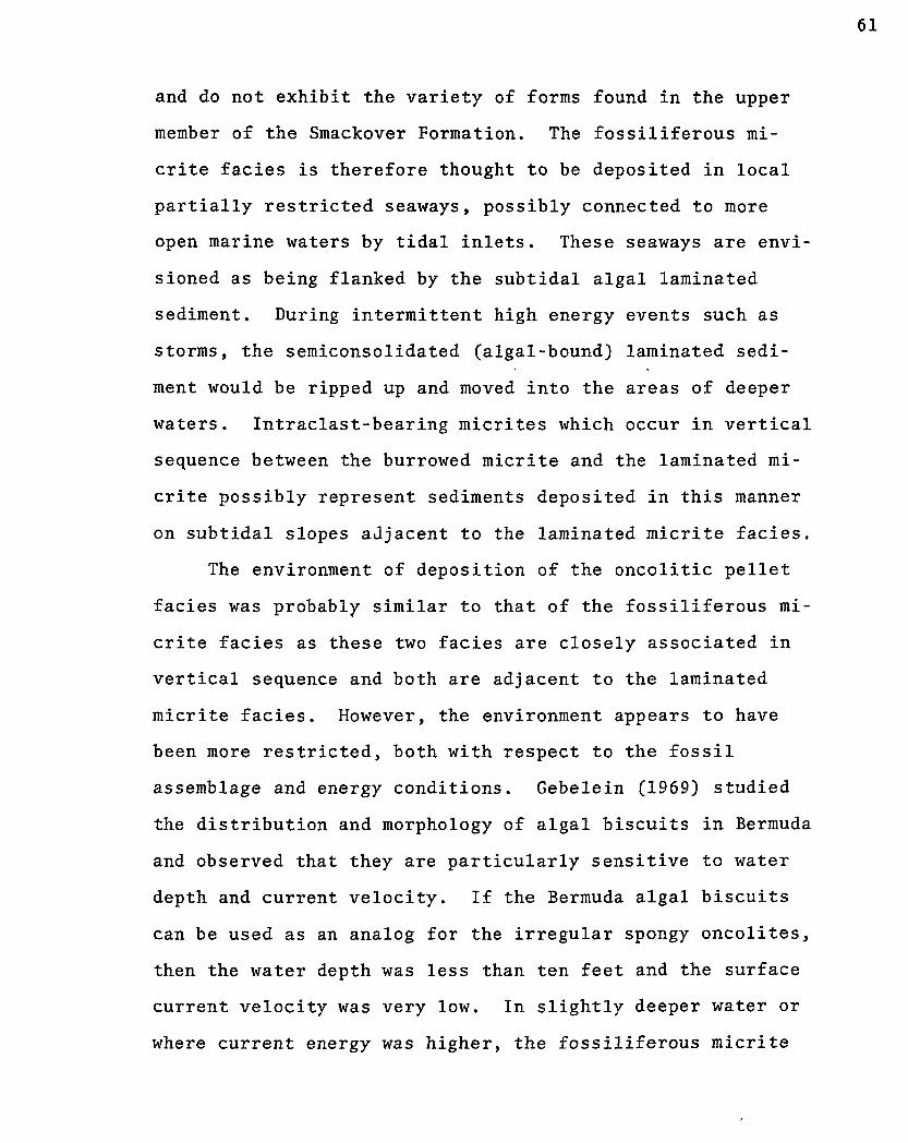
61
and do not exhibit the variety of forms found in the upper
member of the Smackover Formation. The fossiliferous mi
crite facies is therefore thought to be deposited in local
partially restricted seaways, possibly connected to more
open marine waters by tidal inlets. These seaways are envi
sioned as being flanked by the subtidal algal laminated
sediment. During intermittent high energy events such as
storms, the semiconsolidated (algal-bound) laminated sedi
ment would be ripped up and moved into the areas of deeper
waters. Intraclast-bearing micrites which occur in vertical
sequence between the burrowed micrite and the laminated mi
crite possibly represent sediments deposited in this manner
on subtidal slopes adjacent to the laminated micrite facies.
The environment of deposition of the oncolitic pellet
facies was probably similar to that of the fossiliferous mi
crite facies as these two facies are closely associated in
vertical sequence and both are adjacent to the laminated
micrite facies. However, the environment appears to have
been more restricted, both with respect to the fossil
assemblage and energy conditions. Gebelein (1969) studied
the distribution and morphology of algal biscuits in Bermuda
and observed that they are particularly sensitive to water
depth and current velocity. If the Bermuda algal biscuits
can be used as an analog for the irregular spongy oncolites,
then the water depth was less than ten feet and the surface
current velocity was very low. In slightly deeper water or
where current energy was higher, the fossiliferous micrite

62
was favored.
The interpretation of the depositional environments of
the four lithofacies in the main body of the lower member is
shown in the schematic summary diagram (Figure 12). The
lateral distribution of the facies is inferred from their
association in the vertical sequence. These facies do not
represent a continuous progradation or transgression, rather
the facies relationships indicate fairly continuous deposi
tion near mean sea level with carbonate sediment production
essentially maintaining equilibrium with basin subsidence.
Under these conditions, minor changes in this equilibrium
situation would cause lateral shifting of the facies. It
is probable that the entire lower member carbonate section
(300 to 500 feet thick) in this area was deposited under
very restricted, shallow water conditions. The general lack
of fossils or evidence of bioturbation (except for rare
occurrences in the fossiliferous micrite facies) suggests
that no permanent connection with open marine waters existed
during deposition of the lower member.
Upper Member
Stratigraphic Relations
The upper member of the Smackover Formation consists of
several carbonate lithofacies which are thicker and more
widespread than those of the lower member. The lower boundary
of the member is drawn at the contact between pelletoidal mi
crite (upper member) and micrite (lower member) as determined

63
*• MSL-
Z^W&E&Z^z&Z
:"""''-
W T - W T
• ' ' • / . ' • • : ;
Mottled Dolomite
Algal Mats
Micrite
Pellets
5s 4.1 0 g?l T ^ l
1U1
Spongy Oncolites
Fossils
Intraclasts
Burrows
FIGURE 12. Schematic Summary of Paleodepositional Environments, Lower Member of the Smackover Formation

by examination of drill cuttings. Because these two litho-
facies are interbedded, the boundary is often arbitrary, and
the base of the upper member is picked where the sample
lithology changes downward to predominantly micrite. For
mapping purposes, the contact was picked by DIL log corre
lation where drill cuttings were not examined.
The six lithofacies which constitute the upper member
are: pelletoidal micrite facies, superficial oomicrite
facies, pelmicrite facies, oolite facies, oncolitic super
ficial oolite facies, and oolite-quartz dolomite facies.
The stratigraphic relationships of these facies are shown
on the cross section (Plate III) which includes both the
upper member of the Smackover Formation and the lowermost
part of the Buckner Formation. This cross section is con
sidered to be oriented roughly parallel to the depositional
dip direction and includes wells from the Goodwater, East
Nancy, and Harmony Fields, and two wildcat wells in the
northern or up-dip area. The contact between the Smackover
and Buckner Formations is used as the reference datum for
the cross section for all of the wells except the most
northerly well, the Harris #1 Moore 10-12. This well is
lowered on the cross section relative to the other wells
in order to illustrate the inferred facies relationships
between the Buckner and Smackover Formations. For con
venience purposes, the facies relations are illustrated
also on the schematic cross section (Figure 13) which was
simplified from the stratigraphic cross section (Plate III).

el oo I oo I w 1 »» I o o * | J><^ ' • » f * OO \ 00 I Of I oo I 00 I OO ' • - - •
Goodwater Field East Nancy Field
(Lower Member Buckner Formation)
Harmony Field Harris No. 1 Moore 10-12
. . . . - • . . . . j ~ r . oo I oo I op I OO | M i »*"
oo I 00 I 00 I oo I oo I oo
TTTTi
Kggl,
(Lower Member Smackover Formation)
Oolite-Quartz Dolomite Facies
Oolite Facies
Oncolitic Superficial Oolite Facies
ill 0.°\0' Superficial Oomicrite Facies I Art I Art I * * " • r 1 " I OO I oo I
• • I '
S3 nxp: • i • i •
• • • •
Pelmicrite Facies
Pelletoidal Micrite Facies
FIGURE 13. Schematic Cross-Section Showing Relationships of the Six Upper Smackover Lithofacies From Goodwater Field (South to the Most Northerly Well, Harris #1 Moore 10-12 (Diagram taken from Plate III)

The upper member of the Smackover Formation is the most
extensively cored part of the Jurassic section in the eastern
Gulf region. However, the conventional cores are concen
trated in the uppermost part of the member in the more
porous and permeable oolite and oncolitic superficial oolite
facies. In the lower part of the member, only drill cuttings
were available, and consequently much less is known about
the facies in this part of the section. For this reason,
the three upper facies (oolite, oncolitic superficial
oolite, and oolite-quartz dolomite facies) are discussed
in greater detail and the interpretation of depositional
environments is more definitive. In the case of the lower
three facies (pelletoidal micrite, pelmicrite, and super
ficial oomicrite) which were identified primarily on the
basis of rock "chips" recovered during the drilling opera
tion, the facies are more poorly defined, and their inferred
depositional environments less certain.
The upper member ranges in thickness from 300 feet in
the northern part of the study area to 600 feet in the
southern part (Isopach Map, Figure 14). Unlike the lower
member, deposition of the upper member was clearly affected
by salt movement which is best illustrated by thinning over
the East Nancy structure. Possible isopachous closure is
also suggested in the Goodwater and Nancy Fields, but the
data is insufficient to establish definite thickening on
the flanks of these structures. In the area of Harmony and
Pachuta Creek Fields, the Isopach map is similar to that
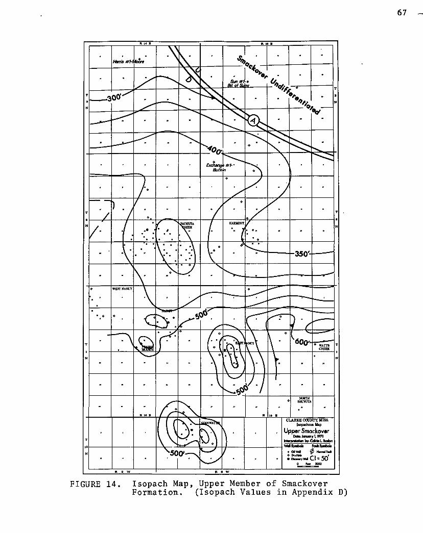
FIGURE 14. Isopach Map, Upper Member of Smackover Formation. (Isopach Values in Appendix D)

shown for the lower horizons and probably reflects a broad
structural salient developed independently of salt movement.
Petrology
The carbonate facies which make up the upper member
are defined primarily on the basis of allochem type and
matrix, as these criteria are thought to reflect more
clearly the environmental conditions at the time of deposi
tion (R. L. Folk, 1959). Table III, p.100 is a summary
chart of the petrology of the upper member which depicts
the relative abundance of allochem types (including detri-
tal quartz), matrix and cement types (micrite/calcspar/
dolospar), and fossil content for each of the six litho-
facies. The three upper lithofacies, oolite facies, on-
colitic superficial oolite facies, and the oolite-quartz
dolomite facies, are treated in more detail as most of the
conventional cores are from this part of the section. The
Getty ifl Coleman 18-15 East Nancy Field was selected as the
reference well (Figure 15) and is considered to be repre
sentative of the upper member. Because of the importance
of the oolite facies and the oncolitic superficial oolite
facies to production of oil and gas, a special section on
cementation is included in this study. These marine beds
are thought to have been buried to their present deep sub
surface position without subsequent exposure to vadose con
ditions; therefore, there is a unique opportunity to study
cementation under continual burial conditions.

CORED SECTION
Core depth corrected to log depth
13580
13590
REFERENCE SECTION Upper Member Smackover Formation
GETTY4H - COLEMAN 18-15 (EAST NANCY FIELD) Section 18, IN-I5E
DIL LOG
13600-
DEEP INDUCTION
CURVE LATEROLOG
CURVE
r--^UCKNER SMACKOVER
OOUTE-QUARTZ DOLOMITE FACIES Irregular fine bedded; fine oolitic dolomitic quartz sandstone: oolites replaced by anhydrite and dolomite
Laminated to irregular fine bedded; arenaceous intraclastic dolomitized oomicrite: calcite oolites and finely xln. dolomite replacing interstitial matrix
13610-
13620-
ir-v'M"-*'
Irregular med, bedded; oolitic arenaceous very finely xln. dolomite
1 Irregular med, bedded; med. Iarenaceous dolomitized oomicrite
13700—
Massive; fine intraclastic oolitic dolomitic quart: sandstone
Massive; arenaceous oolitic finely In. dolomite: oolite molds
"&6UTE FACIES Laminated to fine bedded, S-10° Idip; ned. arenaceous oosparite
13800 —
WVrV.-O
fi&Sfl
1 3 6 3 0 - S
Fine bedded; coarse arenaceous
ne bedded; med. arenaceous oosparite
1 3 9 0 0 -
OdLITE-OUARTZ DOLOMITE FACIES
OOLITE FACIES
' (upper unit)
ONCCXITIC SUPERFICIAL
OOLITE FACIES/'
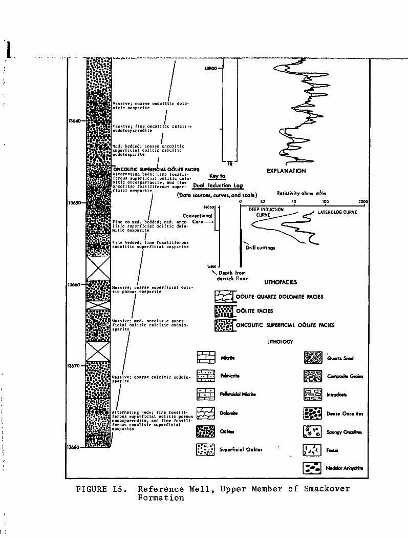
13640-
13650-
13660-
«r4dc>|ii>r* v « ^
13900-
Massive; coarse oncolitic dolo-mitic oosparite
Massive; fine oncolitic calcific oodolosparrudite
Med. bedded; coarse oncolitic superficial oolitic calcific oodolosparite
mm fKU
I ^ ' U E E G & W ^ **rXxtlXE<efr!ar)*jCKBi*rwrii-i
FR
13670-
13680-
14050
Conventional ^o^.-^iFine to med. bedded; med. onco- Cora -S S l t V U r i c superficial o o l i t i c dolo-
ONCOLITIC SUPERFICIAL OdllTE FACIES Alternating beds; fine f o s s i l i - Kav to ferous superficial o o l i t i c dolo- ^ mitic oncosparrudite, and fine -. • , • .. , oncol i t ic foss i l i ferous super- Duol Induction Log ficial oosparite
(Data lourcat, curvos, and seal*) o i.o
EXPLANATION
Resistivity ohms m'/m
10 100 2000
mitic oosparite
/ Fine bedded; fine foss i l i fcrous oncol i t ic superficial oosparite
DEEP INDUCTION CURVE
LATER0L0G CURVE
Drill cuttings
MM0-
\ Dtpth from derrick floor
Massive; coarse superficial oolitic porous oosparite
Massive; med. oncolitic superficial oolitic calcitic oodolosparite
LITHOfACIES
OOLITE-QUARTZ DOLOMITE FACIES
KSKJ06LITE FACIES
ONCOLITIC SUPERFICIAL 0 6 L I T E FACIES
LITHOLOGY
ET3 Mierite Kff lSgf Quartz Sand
Massive; coarse c a l c i t i c oodolosparite
Alternating beds; fine f o s s i l i -ferous superficial o o l i t i c porous oncosparrudite, and fine f o s s i l i -ferous oncol i t ic superficial oosparite
^ > ^ Composite Grains
» a a Introdoth)
• - • m ^ ® g>
l* S
Donto Oncolitat
Spongy Oncottes
Font
Nodular Anhydrite
FIGURE 15. Reference Well , Upper Member of Smackover Formation

70
Pelletoidal Micrite Facies
The Pelletoidal micrite facies occurs at the base of
the upper member and is defined solely on the basis of drill
cutting samples. Interbedded units of dolomitic pelletoidal
micrite which are shown on the stratigraphic cross section
(Plate III) by dotted lines are characteristic of this
facies. The facies appears to be developed throughout the
area although cuttings were not available for examination
in the vicinity of Harmony Field. In the most northerly
well, the Harris #1 - Moore 10-12 (Plate III), the inter
val between 11720 and 11840 feet is included in the pelle
toidal micrite facies. However, in this well the rocks are
more extensively recrystallized to microspar so that the
pelletoidal character is less apparent than in the wells
to the south. Also an anomalous lithology (micrite) was
noted between 11680 and 11720 feet. This unit was not ob
served in any other well in the upper member, and its strati-
graphic relations with other facies is unknown at this time.
In thin section, the drill cutting samples display
rounded or ellipsoidal aggregates of "grains of matrix"
material (Figure 16A). This feature is similar to the
"clotted" texture described by Cayeux, 1970, p. 253 and the
pelleted or pelletoid texture of Bissell and Chilingar,
1967, p. 163. The term pelletoidal micrite is used in this
study to distinguish between underlying micrite (lower mem
ber of Smackover Formation) and overlying pelmicrite in which
pellets with distinct boundaries are embedded in a micrite

71a
FIGURE 16. Photographs: Pelletoidal Micrite Facies and Superficial Oomicrite Facies.
A. Pelletoidal Micrite Facies. Small indistinct pelletlike masses of micrite (p) and secondary dolomite rhombs (d). The dolomite here is not fabric selective, and replaces the pellet-like objects and micrite matrix alike. Thin section of drill cutting fragment.
B. Pelletoidal Micrite Facies. Dolomite (d) almost completely replacing original pelletoidal micrite, with only relict patches of microspar (m) remaining. Thin section of drill cutting fragment.
C. Superficial Oomicrite Facies. Small oblitically coated pellets and smaller size pellets. Inter-stial material is primarily micrite with lesser amounts of calcspar cement.
D. Superficial Oomicrite Facies. Edge of spongy oncolite with center near lower left corner. Small pellets (p) with interstitial open spaces are enclosed between oncolitic laminae (1).

*"•• • • • a '••• , - i : . v . - • - * > .
0.1mm 0.1mm
0.1mm 0.1mm

72
matrix. Dolomite is a common constituent throughout the
facies, and in every well examined, the dolomite content
was found to increase toward the base of the facies. The
size and morphology of the dolomite crystals vary consider
ably, from small irregular patches of dolomicrite to euhe-
dral dolomite rhombs, 0.010 to 0.020mm in diameter, which
occur randomly in the pelletoidal micrite. Where dolomi-
tization is extreme (Figure 16B), micrite is recrystallized
to microspar and appears as relic patches in the predomi
nantly dolomite matrix. Siltsize detrital quartz is slightly
more abundant in the dolomitic beds, but never accounts for
more than five to ten percent by volume of the rock. Fossils
were not found in any of the drill cuttings of this facies.
Superficial Oomicrite Facies
This facies is present only in the central and southern
parts of the area, and overlies the pelletoidal micrite
facies (Figure 13). In the northern part of the area, the
facies was not identified in the only well from which drill
cuttings were available, the Harris #1 Moore 10-12. Cuttings
were not available in Harmony Field, but between Harmony
Field and East Nancy Field, the facies was found in the
Harris #1 Evans 4-4 (WC/Sec. 4, 1N-15E). From East Nancy
Field, the facies thickens into the Goodwater Field area,
and on the north flank of the structure, it underlies and
is interbedded with the oolite facies. On the south flank
of Goodwater Field in the Shell #1 Thomas, beds of the

73
superficial oomicrite facies are interbedded with the pelmi-
crite facies. In general, these two facies cannot be dis
tinguished without the aid of thin sections, as each con
sists of beds which range from irregularly laminated or fine
bedded to burrow mottled. Small spongy oncolites, which
occur "floating" in the finer grained matrix, are common,
but are usuayly difficult to see in hand specimen because
the lack of differential coloration between the oncolites
and the matrix.
Small superficial oolites and pellets are the dominant
allochem types with lesser amounts of spongy oncolites,
composite grains, oolites, and fossils. The superficial
oolites (Figure 16C) range in size from 0.070 to 0.150mm,
whereas the pellets are smaller and usually measure between
0.060 and 0.100mm. The spongy oncolites are smaller and
more tightly packed (Figure 16D), than those described from
the lower member of the Smackover Formation. They appear
to be transitional between the loosely packed spongy on
colites (lower Smackover) and the dense oncolites found in
the oncolitic superficial oolite facies.
Pelmicrite Facies
This facies is present only in the southern area and
was identified in cores from the Goodwater Field and from
drill cuttings in the North Schubuta Field. The facies is
underlain and overlain by the superficial oolite facies and
these two facies are interbedded in the Shell #1 Thomas

(Goodwater Field). The pelmicrite facies also occurs in the
upper part of the section in the Shell #1 Johnston (Plate III),
but lateral continuity of this unit could not be established
in adjacent wells. In the cored section, the beds are simi
lar in appearance to the superficial oomicrite facies ex
cept for the finer grained appearance. The facies is poorly
bedded or irregularly bedded and commonly appears to be ex
tensively bioturbated (Figure 17A, 17B). Algal-coated
fossils (Figure 17B) and spongy oncolites are generally less
prominent than in the superficial oolite facies.
This facies is distinguished from the superficial
oomicrite facies primarily on the basis of thin section
characteristics. Pellets are usually more poorly defined
and are smaller in size than those described from the super
ficial oomicrite facies. The pellets occur both as packed
grains with interstitial micrite and as sparse grains in a
micrite matrix. They are usually deformed and appear to
have yielded plastically during compaction, occasionally
becoming indistinct (Figure 17C). Fossils are less abun
dant and are less varied than in the superficial oomicrite
facies. Punctate brachipods are the most common bioclast
found in this facies, and these generally do not have the
thick micrite coating which is so typical of the fossils
found in the other facies. In addition, there is less
dolomite in this facies than any of the other upper member
facies. The dolomite usually occurs as rhombic-shaped
outlines of micrite sized dolomite (Figure 17D).

FIGURE 17. Photographs: Pelmicrite Facies
A. Conventional Core Slab. Very fine grained pelmicrite with burrow structures.
B. Conventional Core Slab. Burrow mottled pelmicrite and algal coated fossils.
C. Small pellets in pelmicrite rock, and detrital quartz grains (q) with euhedral overgrowths.
D. Closeup of pelmicrite rock showing typical dolomite fabric. Rhomb-shaped dolomite (d) composed of numerous tiny dolomite crystals rather than single crystal rhombs. Brachiopod shell in upper right is not micrite coated.

7§b
.h. i ! | i l l l | l i i l | l i i l | l ! l l | l l l l | i i l i | | | l l | | i l | | l l | | | I METRIC ll j 31 4| si
FIGURE 17

Oolite Facies
The oolite facies is closely associated with the on-
colitic superficial oolite facies and together they form
the principal oil and gas reservoirs in the Smackover For
mation. But, because the two facies have similar porosity
characteristics, they cannot be differentiated by geophysi
cal well logs and consequently can only be defined by drill
cuttings and conventional core analysis. Throughout much
of the area, the oolite facies consists of an upper oBlite
unit and a" lower oolite unit which are separated by the on-
colitic superficial oolite facies. These relationships can
be seen on the stratigraphic cross section (Plate III) and
on the schematic cross section (Figure 13). Along the line
of section (Plate III), the oolite facies is present from
Goodwater Field on the south to Harmony Field on the north,
but may be absent in the area to the north of Harmony Field.
The facies exhibits considerable variation across this area,
both in petrology and relation to adjacent facies. To the
south in Goodwater Field, the facies is interbedded with the
superficial oomicrite facies, and in Harmony Field on the
north, the facies is interbedded with the oolite-quartz
dolomite facies. However, the facies relations appear to
be fairly consistent in the east-west direction and the
oolite "belt" is thought to extend eastward into Watts
Creek and North Shubuta Fields and westward into Nancy and
Pachuta Creek Fields (Figure 14). East Nancy Field, which
is near the center of the oolite belt, is therefore a

convenient reference for discussion of the updip (north)
and downdip (south) variations in the upper and lower ooli
units.
The lower oolite unit is approximately one hundred
feet thick in East Nancy Field where it overlies the super
ficial oomicrite facies and underlies the oncolitic super
ficial oolite facies. The lower unit consists of thick
bedded homogeneous oolites in which stratification is usua
not noticeable unless accentuated by the presence of the
larger dense oncolites and algal coated fossils. Commonly
thin beds of oncolites and fossils which appear to have
been deposited as "lag" concentrates are interbedded with
thicker beds of homogeneous oolites (Figure 18A). To the
north, the lower unit is probably continuous into Harmony
Field as oolite fragments were detected in drill cuttings
from the Harris #1 - Evans 4-4 which lies between the two
fields. In the downdip area (Goodwater Field), the oolite
facies is poorly developed and characteristically inter
bedded with the superficial oomicrite facies. As no wells
were drilled between East Nancy and Goodwater Fields, it
cannot be determined if the facies is continuous between
the two fields.
The lower oolite unit in East Nancy Field consists pr
dominantly of well developed oolites with pellet nuclei al
though quartz nuclei are fairly common in sequences with
high detrital quartz content. Superficial oolites are the
next most abundant allochem and are always present giving

FIGURE 18. Photographs: Oolite Facies
A. East Nancy Field, lower ofilite unit. Fine grain oolites interbedded with "lag" concentrated layers of dense oncolites and algal coated fossils.
B. Harmony Field, lower oolite unit. Small scale cross-stratified arenaceous oolites. The larger grains are primarily composite grains.
C. Harmony Field, upper oolite unit. Thick bed of small dense oncolites, algal coated fossils and composite grains. Unit is interbedded with oolite beds.
D. Harmony Field, upper oolite unit. Rare occurrence of spongy oncolites in oolite facies. Matrix composed of composite grains and oolites.

78b
I1 ' ' i ' . n i 1 1 i,(••in ' i n i i i ! • , . f in i t iMt iMi I MEIBIC l| 2| 3| 4! 5
FIGURE 18

the rock a typical bimodal texture. Oncolites are exclu
sively of the dense type (Figure 19C) and are most frequen
tly found where superficial oolites are a significant con
stituent.
The upper oolite unit in East Nancy Field is best deve
loped in the reference well (Figure 15) where the unit is
overlain by the oolite-quartz dolomite facies and grades
downward into the oncolitic superficial oolite beds. At
the top of the unit, the strata are fine bedded and are
inclined at 10 to 15 degrees to the bore hole. Near the
base of the unit, the beds are more coarsely bedded and
stratification is essentially horizontal. In the upper
part of the unit, dense oncolites are rare, but increase
in abundance conspicuously near the base where the super
ficial oolite facies is interbedded. To the north in
Harmony Field, the upper unit is quite different both in
stratification and allochem types. The oolite beds are
poorly stratified and contain thick beds of the larger
allochems, dense oncolites, algal coated fossils (Figure
18C) and less frequently smaller composite grains and intra-
clasts. Near the top of the unit, thin beds of nodular
anhydrite are commonly interbedded with the oolitic beds.
In the upper oolite unit in the East Nancy Field, the
oolite allochems exhibit a distinctive vertical variation
from top to bottom. Near the upper boundary, the oolites
are small (0.3 to 0.4mm) and well sorted, whereas near the
base the oolites are larger (0.8 to 1.0mm) and poorly sorted

because of the admixture of superficial oolites. Dense
oncolites, fossils, and superficial oolites are common
only near the base where the oolite beds interfinger with
beds of the oncolitic superficial oolite facies. In Harmony
Field, the upper oolite unit contains a distinctive variety
of allochems which are generally unlike any found in the
oolite beds to the south. Here the oolites are poorly
developed and commonly contain two or more nuclei. Com
posite grains (botryoidal type, Illing, 1954) are the
second most abundant allochem and are distinguished from
the multiple nuclei oolites only by having a thinner coating.
Intraclasts consisting primarily of micrite make up as much
as twenty percent of the allochems in some beds and are
notable because of their absence in oolite beds elsewhere.
The fossils found in the oolite facies are a typical
marine assemblage consisting of echinoiderms, algae (soleno-
paracean and codiacean algae), corals, bivalves, brachiopods,
and gastropods. The fossils are almost always heavily coated
with micrite which is thought to be algal in origin as a com
plete transition exists between fossils with thin micrite
coating and oncolites with fossil nuclei. The process of mi-
critization of grains by endolithic algae (Bathhurst, 1966)
which results in a micrite envelope around grains appears to
have had some effect on the fossils. However, where the
fossil fragment size is greatly increased, the process is
clearly accretionary and probably due to algal encrustation.
The o'dlite beds appear to have been deposited with high

primary porosity as the rocks are essentially free of inter-
stial micrite. Subsequent compaction and pore-filling
cementation have only partially reduced the porosity, and
consequently these rocks are an excellent reservoir for
hydrocarbons. The cementing materials are sparry calcite
(calcspar), sparry dolomite (dolospar), and rarely anhy
drite. These cements occur in six different fabrics in
what is thought to be stages in a progressive sequence of
cementation. Because a similar sequence was found in the
oncolitic superficial oolite facies, the cements of both
facies are discussed together under the section "Cementa
tion of Oolite and Oncolitic Superficial Oolite Facies."
Oncolitic Superficial Oolite Facies
The oncolitic superficial oolite facies appears to be
restricted to the central and northern parts of the oolite
belt and was identified in cores from the East Nancy and
Harmony Fields (Figure 13). To the south in Goodwater
Field, the facies does not appear to be present although
small superficial oolite beds are occasionally interbedded
within the oolite facies.
The facies can be distinguished from the oolite facies
by finer grain size and abundance of oncolites and algal
coated fossils. The overall appearance of this facies is
one of alternating beds of superficial oolites and thinner
beds of packed oncolites and algal coated fossils. The on-
colite beds range from one grain thick to as much as one

82
meter thick, but most commonly measure several centimeters
in thickness (Figure 19A). The thicker superficial oolite
beds usually have prominent dense oncolites and algal coated
fossils floating in the superficial oolite matrix (Figure
19B).
The most common allochem types in order of abundance
are pellets, superficial oolites, dense oncolites, oolites,
and algal coated fossils. The superficial oolites always
result from oolitic coating of pellets, and these two allo
chems are always found together. Both the superficial
oolites and pellets are very uniform in size, ranging from
between 0.080 to 0.150mm in diameter. It should be noted
that the superficial oolites and oolites do not constitute
a continuous oolitic series, but rather when found together,
the resulting texture is strikingly bimodal (Figure 19D).
Evidently the environmental conditions responsible for
formation of the superficial oolites were distinctly dif
ferent from that of the oolite facies. Also the super
ficial oolite facies appears to represent conditions most
suited for oncolitic growth, as the dense oncolites here
are both larger and more abundant than in the oolite facies.
The nucleus of the oncolites are usually fossils or pellet
aggregates, but many appear to have no discrete nucleus.
Fossils are always algal coated (Figure 19B), and occasion
ally make up as much as 20 to 40 percent of the allochems in
the packed oncolite beds. A continuous oncolite series is
present from algal coated fossils (where the oncolitic

FIGURE 19. Photographs: Oncolitic Superficial Oolite Facies
A. Typical Appearance of Superficial Oolite Facies. Small beds of dense oncolites and algal coated fossils alternating with beds of superficial oblites.
B. Thick Bed of Dense Oncolites and Algal Coated Fossils. A complete transition exists between algal coated fossils and dense oncolites with fossil nuclei. Shapes of oncolites are frequently controlled by shell nucleus. Large radist at center left.
C. Typical Texture of Oncolitic Superficial Oolite Rock. Laminations are not apparent in large oncolites (compare with spongy oncolite texture, Figure 16D). Oncolites are packed with matrix composed of superficial oolites and detrital quartz. Photographed in plane light.
D. Internal Structure of Allochems and Fabric Controlled Cements. Dense oncolites at left exhibit crude oncolitic laminations, oolites at right have thick oolitic laminations, and smaller superficial oolites have thin oolitic laminations. Superficial oolites cemented by thin calcite crust (cc) in upper part, and oolites and oncolites cemented by blocky calcspar (be). Note grain penetration more severe at oolite and oncolite contacts, but only slight at superficial oolite contacts.

83b
1.0 mm 0.1mm

coating is less than one-third the radius of the fossil
nucleus) to dense oncolites (where the coating is greater
than one-third the radius of the nucleus). The most fre
quently occurring fossils are algae including Soleno-
poroaceae and Codiaceae. Other fossils less commonly found
are echinoderm plates and spines, high spired gastropods,
and bivalves.
Oolite-Quartz Dolomite Facies
This facies is restricted to the uppermost part of the
Smackover Formation and underlies the lower member of the
Buckner Formation. The stratigraphic position of the facies
and its relation to adjacent facies is illustrated in Figure
13. In the East Nancy Field, the oolite-quartz dolomite
facies overlies the upper unit of the oolite facies; in the
Harmony Field, the facies overlies and is interbedded with
the oolite facies; and in the most northerly well (Harris
#1 Moore 10-12), it overlies the basal pelletoidal micrite
facies. The facies does not appear to be present in Good-
water Field near the southern boundary of the study area.
The rocks which make up the oolite-quartz dolomite
facies are composed primarily of dolomite, with variable
amounts of oolites and detrital quartz. Because of the
high dolomite content, the strata are usually lighter
colored than the other facies of the Smackover Formation.
Stratification is poorly developed and the rocks are typi
cally wavy or irregularly bedded (Figure 20) but occasionally

85a
FIGURE 20. Photographs: Oolite-Quartz Dolomite Facies
A. Algal Laminated Dolomite. Typical gradation from nonlaminated oolitic dolomite at base into probable algal laminated dolomite. The algal lamination in turn grades into intraclastic dolomite.
B. Alternating small beds of intraclastic dolomite and nodular anhydrite. Anhydrite nodules are closely packed and form a nodular mosaic outlined by seams of interstial dolomite.
C. Oolitic dolomitic micrite from Harris #l-Moore 10-12 showing typical mottled appearance. Darker patches are poikiloblastic anhydrite, (thin section Figure 21E taken from this slab).
D. Irregular Bedded Dolomitized Oomicrite. Rock contains packed calcite oolite and interstitial dolomite (thin section Figure 21A taken from this slab).
E. Massive Dolomitized Oomicrite. Packed calcite oolites and intrastial dolomite. Large irregular dark patches are clusters of lath-shaped poikiloblastic anhydrite.
F. Arenaceous intraclastic dolomite with shale partings. Large intraclast are composed primarily of aphanocrystalline dolomite; matrix composed of very finely crystalline dolomite and sand-sized quartz.

85b
|iFiiirrnnrnpiirrnn|iiii|iiiiiniiirrii| mil
FIGURE 20

86
appear as homogeneous or massive. Small beds of nodular
anhydrite (Figure 20B) are commonly present, but these
rarely exceed a few inches in thickness. Small zones of
irregularly laminated dolomite (Figure 20A) are also
associated with the nodular anhydrite and are very similar
in appearance to algal laminated sediment reported by
numerous authors from the modern intertidal and supratidal
environments (Shinn, et al., 1969).
Several rock types are included in this facies: oolite
and quartz bearing dolomites (less than ten percent grains
in dolomite matrix), oolitic and arenaceous dolomites (be
tween 10 and 30 percent grains in dolomite matrix), dolomi-
tized oomicrite* and dolomitic quartz sandstones (packed or
grain supported oolites or quartz grains with dolomite
matrix). Also present, but in minor amounts, are intra-
clastic dolomite, nodular anhydrites in aphanocrystalline
dolomite (< 0.004mm) and oosparite beds. The basis for
grouping these different rock types into one lithofacies
is similarity of depositional texture and diagenetic altera
tion. The dolomite is fabric selective, in that it replaces
only the matrix material and does not appear to affect the
allochemical grains. This interstitial dolomite matrix
\tfhich is characteristic of all of the rock types except
the oosparite is thought to be an early diagenetic replace
ment of lime mud (see section on Dolomitization of Oolite-
*Term used to describe replacement dolomite matrix between packed calcite oolites.

87
Quartz Dolomite Facies). Consequently, the rocks represent
deposition under low energy conditions as suggested by Folk,
1962, p. 67, "Microcrystalline Allochemical Rocks." Addi
tional diagenetic features which are common to the facies
include dissolution (leaching) of calcareous allochems and
subsequent void-filling precipitation of anhydrite, cal
cite, and sparry dolomite. The petrography of the most
frequently occurring rock types is described below.
Oolite and Quartz Bearing Dolomite
In these dolomite beds, oolites and said size quartz
are the most common grain types and occur floating in a
matrix of very finely crystalline dolomite (0.005-0.016mm).
The manner in which the oolites are altered diagenetically
is the most characteristic aspect of these rocks. In this
respect, they are identical with the mottled dolomite beds
described from the Lower Smackover. At the base of the
facies, the oolites are commonly dissolved (Figure 21B)
giving the rock an obmoldic texture which is outlined by
the interstial dolomite. Higher in the section, the sites
of former oolites are filled with either calcite, anhydrite,
or less commonly dolomite. The calcite always occurs as
single crystals (Figure 21D), and the anhydrite usually
occurs as two or more prismatic crystals (Figure 21D). In
the less common situation where dolomite fills the oolite
site, the dolomite crystals are subhedral and tightly packed
(Figure 11B). The single crystals of calcite are most

FIGURE 21. Photographs: Oolite-Quartz Dolomite Facies
A. Dolomitized Oomicrite. Calcite oolites (o) with interstitial finely crystalline dolomite. The dolomite is fabric selective, replacing probable lime-mud matrix.
B. Oomoldic Fabric. Interstitial very finely crystalline dolomite (d), quartz grains and oolite molds (o). Early dolomitization of interstial material and subsequent dissolution of oolites forming otilite molds.
C. Closeup of dolomitized oomicrite. Calcite oolite with interstial penetrating dolomite rhombs. Compare with Figure 23B (dolospar cement).
D. Anhydrite (a) and single crystal of calcite (c) filling probable oomoldic cavities. Very finely crystalline dolomite (d) in the interstice.
E. Typical diagenetic fabric in Harris #l-Moore 10-12. Interstitial material is microspar (m) and allochems are replaced by small crystals of dolomite (d).
F. Poikiloblastic anhydrite. Lath shaped anhydrite crystals (a) replacing calcite allochems, but not interstitial dolomite (d).

88b
0.1mm 0.1mm
0.1mm J0.1mm
0.1mm FIGURE 21 0.1mm

89
commonly found near the base of the facies whereas anhydrite
is dominant in the upper part of the facies. It could not
be established definitely whether the oolites were first
dissolved (oolite molds) and subsequently filled by chemi
cally precipitated cements; or that the anhydrite, calcite,
and dolomite occurred by selective replacement of oolites.
The presence of oolite molds at the base of the facies
suggest that oolites throughout the facies were dissolved
and later filled by chemically precipitated cements. This
process may also explain the absence of fossils in this
facies, although it should be noted that no fossil molds
were identified. The time of dolomitization of the inter
stitial material is evidently prior to dissolution of the
allochems as the molds are preserved by the surrounding
dolomite.
Oolitic and Arenaceous Dolomites
In these rocks, the combined oolite and detrital quartz
content is between 10 and 30 percent. Consequently, the
grains are sparse (matrix supported) and occur floating in
a very finely crystalline dolomite matrix. Where the oolites
are a minor constituent (i.e., arenaceous dolomite), the
original oolites are diagenetically altered to anhydrite,
single crystals of calcite or sparry dolomite as described
in the oolite bearing dolomites. Where oolites account for
20 to 30 percent of the grain content, the oolites are fre
quently as well preserved as those in the oolite facies.

90
Evidently the tendency for dissolution of calcareous oolites
and subsequent void filling by anhydrite, calcite, or dolo
mite is related to the relative amounts of oolites present
in the rock. As was noted in the oolite bearing dolomites,
calcite casts are more common near the base of the facies
whereas anhydrite casts predominate in the upper part of
the facies.
Dolomitized Obmicrite and Dolomitic Quartz Sandstones
Dolomitized oomicrite refers to packed calcareous
oolites with interstitial finely crystalline replacement
dolomite (0.016-0.062mm). The term is used in order to
distinguish between packed oolites with fabric selective '
dolomite matrix and packed oolites with chemically precipi
tated interstitial dolomite cement (otfdolospar). Evidence
for the interpretation of replacement dolomite is cited in
"Dolomitization of the Oolite-Quartz Dolomite Facies" and
criteria for distinguishing between replacement dolomite
and dolomite cement are discussed. The size of the replace
ment dolomite in the packed oolite beds is generally larger
(finely crystalline), than in the sparse oolite beds des
cribed earlier (very finely crystalline). The calcareous
oolites are uneffected except for dolomite penetration at
the outer edges of the oolites. Pressure solution at grain
contacts is lacking, and finely crystalline dolomite com
pletely fills the interstices (Figure 21A,21C). Occasionally,
large clusters of anhydrite crystals are present (Figure 20E,

21F) which replace the calcareous oolites but not the
interstial dolomite. Because these anhydrite crystals
always contain dolomite inclusions, they are referred to as
"Poikiloblastic" and should not be confused with the lensoid
anhydrite (pseudomorphic after gypsum) described from the
laminated micrite facies of the Lower Smackover.
In the dolomitic quartz sandstone beds, the grains con
sist primarily of sand-sized quartz with lesser amounts of
feldspar and casts of allochems. The interstitial material
is usually finely .crystalline dolomite except where the dolo
mitic sandstone occurs near the top of the facies in which
case anhydrite is equally abundant. The dolomite is thought
to be a replacement of original lime mud matrix as is evi
dently true where the grains are sparse or "mud supported."
In addition, the fabric of the dolomite crystals is similar
to the dolomite crystals in the dolomitized oomicrite beds
and differs significantly from the dolospar cement observed
in the oolite facies. It is therefore probable that the
dolomitic sandstone beds originr.lly had a lime mud matrix
with subsequent replacement of lime mud by finely crystal
line dolomite.
Harris #1 - Moore 10-12
The dolomitic strata in the Harris #1-Moore which are
included in the oolite-quartz dolomite facies are described
separately because of their unusual diagenetic character.
These rocks are thought to be part of the oolite-quartz

92
dolomite facies primarily because of the similarity of
inferred primary depositional texture (oolite and detrital
quartz with interstial lime mud matrix). However, the char
acter of diagenetic alteration is completely unlike that
described for the oolite-quartz dolomite facies in wells
to the south. The strata consist of alternating beds of
sparse (Matrix supported) allochems and packed (grain sup
ported) allochems in which the allochems are replaced by
dolomite and the matrix is composed of microspar (0.005 to
0.030mm) and occasionally pseudospar (> 0.030mm). The
allochems are thought to be oolites because of their size,
good sorting, and general spherical shape. Using the cri
teria for distinguishing between neomorphic calcite and
sparry calcite suggested by Folk, 1965, p.44, it appears
that chemically precipitated sparry calcite is not present.
It therefore seems likely that these rocks originally had
a lime mud matrix as was inferred for the rocks in the
oolite-quartz dolomite facies to the south. On this basis,
the dolomitic strata in the Harris #1 Moore well are in
cluded as part of the oolite-quartz dolomite facies.
Dolomitization of Oolite-Quartz Dolomite Facies
In this facies, the dolomite is referred to as fabric
selective as it affects only the interstitial material and
not the allochems. The dolomite consists of nonferroan
crystals which range in size from aphanocrystalline to
medium crystalline. However, three sizes are most frequently
93
found, aphanocrystalline (0.003-0.006mm), very finely
crystalline (0.010 to 0.020mm), and finely crystalline
(0.020 to 0.060mm). In this section, the origin of the
fabric selective dolomite is considered as well as a possible
explanation for the size ranges. In addition, criteria are
established for differentiating between interstitial replace
ment dolomite and interstitial precipitated dolomite (dolo-
spar).
The three dolomite size ranges appear to be related to
primary depositional texture; aphanocrystalline dolomite is
always associated with nodular anhydrite, very finely crystal
line dolomite most frequently occurs as the matrix between
sparse allochems, and finely crystalline dolomite is usually
present in the interstices between packed allochems. In
the case of the aphanocrystalline and very finely crystalline
dolomites, the origin of the dolomite is more apparent. In
these rocks, the allochems are usually dissolved and may
appear as molds (oomoldic, Figure 21B) or as casts (Figure
21D) in which the casts are composed of single crystals of
calcite, anhydrite laths, or less commonly large subhedral
crystals of dolospar. Because the dolomite preserves the
primary texture of the rock, dolomitization evidently
occurred prior to dissolution of the allochems. The dolo
mite preferentially replaced the matrix material, but not
the allochems which were dissolved during a later diagenetic
phase. As these rocks have a "matrix supported fabric," it
is probable that the dolomite preferentially replaced the

original lime mud matrix.
The origin of the fabric selective dolomite is less
apparent in the packed or "grain supported" oolite beds
because the oolites are as well-preserved here as in the
oolite facies. For this reason, it is necessary that a
distinction be made between interstial replacement dolomite
and interstitial precipitated dolomite (dolospar). Al
though differences in size are usually apparent, the manner
in which the dolomite rhombs are oriented with respect to
the oolite boundary is the most significant difference. As
illustrated in Figure 21C, the typical orientation of re
placement dolomite crystals is with the apex of the rhombs
penetrating the oolite grain boundaries. This should be
compared with Figure 23B from the oolite facies where the
rhombs are usually oriented with the flat face parallel to
the grain surface. Although exceptions to the general
rule of small penetrating rhombs in the dolomite facies,
and large nonpenetrating rhombs in the oolite facies were
noted, the overall fabric contrast is striking. There were
few thin sections in the oolite facies or the oolite-quartz
dolomite facies which did not conveniently fit into one of
the two dolomite fabrics. The interstitial penetrating
dolomite is also considered to be replacement of lime mud,
and therefore is referred to as dolomitized obmicrite. Evi
dence for this is afforded by the different kinds of oolite
beds within the facies (dolomitized oomicrites and oosparite
beds). In the oosparite beds, extreme pressure solution at

grain contacts is evident prior to precipitation of the
calcspar cement. These beds were apparently well winnowed,
with primary interstitial void space. By contrast, the
adjacent oolite beds with interstitial dolomite show no
grain penetration even when grains are closely packed. It
would appear that these units were poorly winnowed with
lime mud still present in the interstices. An alternate
possibility is that the dolomitized oomicrite beds were
cemented by dolomite prior to compaction. However, this
idea is rejected because the obsparite beds which are ad
jacent to the dolomitized oomicrite beds show no evidence of
dolomite cement. Also, the penetrating habit of the dolo
mite rhombs could be more easily accomplished if nucleation
occurred within the lime mud matrix. In this manner, crys
tal growth could occur easily in all directions away from
the nucleation site, resulting in penetration of the oolites
during dolomite growth and replacement. By contrast the
dolospar crystals indicate preferred growth into the inter
stitial void space.
Preferential dolomitization of lime mud in poorly
winnowed calcarenites has been noted by many authors (Thomas
and Gliester, 1960; R. D. Perkins, 1963; and Murray and
Lucia, 1967). It seems most reasonable that dolomitiza
tion occurs early, before burial, while the lime mud is stil
porous. The process is of course enhanced where detrital
dolomite is available to act as seed crystals and if mag
nesium rich fluids are available near the depositional site.

The origin of the aphanocrystalline dolomite is perhaps the
most easily explained. Because of its close association
with anhydrite nodules (see discussion of anhydrite nodules,
"Depositional Environment of Lower Buckner Formation"), the
aphanocrystalline dolomite is thought to be syngenetic,
formed under supratidal conditions. Penecontemporaneous dolo
mite which is less than 0.005mm in size has been reported
from the supratidal in the Bahaman area (Shinn, et al., 1965)
and from the Persian Gulf area (Illing, et al., 1965). How
ever, the reasons for the two larger dolomite sizes are more
problematical. The very finely crystalline and finely crys
talline dolomite sizes appear to be related to geographic
position within the depositional environment; that is,
proximity to the supratidal. If the relative percentages
of oolites are used as an indicator of depositional current
energy, then the oftlite-bearing dolomites were nearest the
supratidal environment. Therefore, the three dolomite size
ranges appear to be related to geographic position at the
time of deposition so that; aphanocrystalline dolomite
occurs in the supratidal environment, very finely crystal
line dolomite occurs in the proximal beds, and finely
crystalline dolomite in the distal beds. As the dolomite
is thought to be an early diagenetic replacement, it seems
reasonable to assume that the source of dolomitizing fluids
was the supratidal area where Mg-rich pore waters were con
centrated. However, no explanation is apparent to explain
the possible correlation between geographic position and

97
and dolomite size. Also, the relationship between dolomi-
tization and dissolution of the sparse oolites is not clear.
Because the two features are always found together, it
suggests a common link. By contrast to the packed o'olite
beds in which the finely crystalline dolomite is both larger
and less uniform, there is no evidence of dissolution of the
calcite oolites. It is possible that these more distal
units were less affected by refluxion of dolomitizing fluids
(Adams and Rhodes, 1960).

Depositional Environments of Upper Member
of the Smackover
The pelletoidal micrite facies at the base of the upper
member possibly represents a compacted pellet mud deposited
under subtidal low energy conditions. Because this facies
appears to be thicker and more widespread than the Lower
Smackover facies, the pelletoidal micrites may represent
more open marine conditions. However, the presence of
fossils could not be definitely established as the facies
was identified solely on the basis of drill cutting samples.
The interbedded dolomite units appear to be related to
proximity of the shoreline, as these are more common in
the northern or updip wells. Evidence of shoaling, how
ever, was found only in the most northerly well, the
Harris #1 Moore 10-12 which contained small sparse allochems.
The superficial obmicrite facies overlies the pelle
toidal micrite facies and is in part equivalent to the
oolite facies updip and the pelmicrite facies downdip. In
the vicinity of East Nancy Field, the superficial oomicrite
facies is relatively thin and reflects a consistent change
from subtidal low energy pellet formation at the base to
high energy oolite sand at the top. The vertical increase
in energy conditions may also be expressed by the upward de
crease in lime mud matrix (micrite). The superficial oomi
crite facies is considered to have been deposited on the
seaward flank of the oolite shoals and in the Goodwater
Field, deposition of the superficial oomicrite facies

99
persisted until near the end of the upper- Smacko^er^ The
allochem types and presence of interstitial micrite indicate
a poorly agitated subtidal environment in close proximity
to shoal waters. The echinoids, bivalves, algae, brachi-
pods, and gastropods (Table III) suggest generally open
marine conditions, and the thick algal coating of the fossils
indicate at least intermittent agitation. Across Harmony
Field to the north, data was not available so that the con
tinuation of the facies could not be established. On the
northwest flank of the field in the Exchange #1 Bufkin 6-7,
the geophysical logs suggest "limestone porosity" over the
interval 12400 to 12500 feet. If this log interpretation
is correct, it is probable that shoaling conditions deve
loped in this area, in a position updip from the superficial
obmicrite facies.
The pelmicrite facies was encountered only in the
Goodwater and North Shubuta fields, in the southern part
of the area. As the facies consists of pellets and spongy
oncolites with a predominance of micrite matrix, it is
evident that the pelmicrite facies was deposited under lower
energy conditions than the superficial oomicrite facies.
From its position in the section (Plate III and Figure 13),
it appears that the pelmicrite facies represents the deepest
water deposition, basinward of the subtidal superficial oomi
crite facies. However, the presence of spongy oncolites,
and the relatively restricted macrofauna (predominantly
brachipods and echinoids) mitigates against open marine

TABLE I I I . Summary Chart , Petrology of the Upper Member of the Smackover Formation.
LITHOFACIES
0 6 l i t e - Q u a r t z Dolomite Fac ie s
O n c o l i t i c S u p e r f i c i a l O o l i t e F a c i e s
O o l i t e F a c i e s
Pe l jn icr i te F a c i e s
S u p e r f i c i a l Oomicrite F a c i e s
P e l l e t o i d a l M i c r i t e Fac ie s
+ ALLOCHEM TYPE
DETRITAL QUARTZ Order of abundance
* (Volumet r ic R a t i o )
01 4-> •H H
8
to 4J <D t-i fH 0)
CO
0)
•rt 8
CO
<u H H
10 V
a a.
in 0)
r-4 CD
N
U
m
&
H CO •ri in o <u •rt 4J *U f-C
a) to Q . O 3 in
H
« • r t tf> CM -rt
aito a o
10
D>«rt C .rt o o Ot u w c
o
H ID •M O
o a> •rt U U-t -rt I J r t a>:o a o
N
11
o*
10
(/> a o
2 C M
0]
a; i-> C H 3 O
—
F o s s i l s O o l i t e s
Quartz F o s s i l s
Rounded O n c o l i t e s
10
•H CO 10
£
o ^ <" tjl *rt C H
Q. U W C
o
F o s s i l s O o l i t e s
Order FOSSILS of abundance
* (Volumet r ic R a t i o )
u id
rt
CO T3
C
o u
CO •o o
o •rt o s
(0 T> •H O
c £ U
Ul TJ •ri O c
s . u
u
co a> >
H 18
> m
•o o Q ,
2 4J 10
S
ul HI
> 3
•H
Coral B i v a l v e s Gastropods
Algae Echinoids B i v a l v e s Gastropods
Algae Brachiopods
Gastropods
7
MATRIX-CEMENT MICRITE/CALCSPAR/DOLOSPAR
Order of abundance * (Volumet r ic R a t i o )
M i c r i t e rep laced by e a r l y d i a g e n e t i c dolomite
Calcspar
Dolospar
Micr i t e
Micr i t e
M i c r i t e
Dolomite
Micr i t e
Calcspar
Calcspar
"
~ ~

conditions. Ginsburg (1960) noted that oncolites have not
been reported from water depths greater than eight feet.
Whether the pelmicrite facies is "basinal" or a restricted
shelf environment cannot be determined within the study
area.
The lower unit of the oolite facies was deposited in
well agitated high energy shoals, and appears to form a
linear band of deposits approximately ten miles wide and
trending east-west across the study area. The generation
of accretionary allochems evidently kept pace with basin
subsidence, resulting in a thick sequence of oolite sands.
The subtidal superficial oomicrite facies is considered to
have been deposited on the seaward side of the oolite sand
belt, and the oncolitic superficial oolite facies on the
landward side in slightly deeper water with less vigorous
agitation. The accretionary oolites formed under active
tidal action on shoals developed parallel to the coastline.
There is no evidence of a controlling shelf break in the
study area such as that described from the present day
Bahaman oolite belt (Ball, 1967). Rather the Smackover
oolite belt appears to have built up as a consequence of
the intersection of a gently sloping sea floor and wave base.
The degree to which locally intrusive salt movement may
have modified the bottom topography and oolite shoal morpho
logy during this time is considered in the section on "Struc
ture and Depositional History." The main body of the oolite
facies (lower unit) is thought to be continuous from the

102
north flank of the Goodwater Field on the south through
Harmony Field on the north. Goodwater Field is situated
near the seaward edge of the belt, as the area is domi
nated by the subtidal superficial oomicrite and pelmicrite
deposits. In the Goodwater area, high energy oolite shoal
deposits are present only near the top of the Smackover
Formation where the oolite bank prograded southward. In
East Nancy and Harmony Fields, the lower unit of the
oolite facies exceeds one hundred feet in thickness and
evidently indicates equilibrium between deposition and
subsidence. During rare periods of sustained subaerial
exposure, beds of displacive nodular anhydrite were deve
loped over the oolite shoals.
The oncolitic superficial oolite rocks were deposited
landward of the oolite shoal banks and indicates less ac
tive current action. The current activity was sufficient
for the formation of a thin oolitic coating on pellets, but
apparently not vigorous enough to develop oolites. This
moderately sheltered depositional area represents the most
favorable site for growth of the dense oncolites, as these
are much more abundant and larger than those found in the
oolite facies. Evidently the blue-green filamentous algae
which coated the free-lying grains require less vigorous
agitation than that necessary for oolite growth.
The upper oolite unit in East Nancy Field which sepa
rates the superficial oolite facies from the oSlite-quartz
dolomite facies is thought to be a barrier beach deposit.

Sedimentary-dip angles of 10 to 15 degrees may represent
beach accretion beds, indicating a relatively high energy
beach. In Goodwater Field, the oolite beach does not
appear to be present, and here the oolite-quartz dolomite
facies is thin or absent. In Harmony Field, the upper
part of the oolite facies varies considerably from that
observed in the East Nancy Field and consists predominantly
of composite grains and poorly sorted matrix. The compo
site grains are similar to the boitryoidal lumps described
by Purdy (1963, Part 1), and probably represent early cemen
ted aggregates with thin oolitic coating. These composite
grains are thought to have been deposited in sheltered areas
which lack appreciable bottom currents and probably with
intermittent periods of bottom stability.
The various beds included in the oolite-quartz dolo
mite facies are thought to be deposited in a lagoon which
formed landward of the barrier beach sequence. A protected
low energy environment is evident from the dominant litho-
logic characteristics; mud supported allochems and terre-
genious rocks with preferential dolomitization of the lime
mud. Associated lithologies such as oosparite beds and
dolomitized oomicrite beds are considered to be washover
deposits from the oblite barrier beach. The intermittent
small beds of displacive nodular anhydrite in aphanocrys-
talline dolomite matrix, were probably deposited in salt
flats (sabkhas) which developed on emergent mud banks.
These areas would be susceptible to formation of the

supratidal displacive nodular anhydrites which are similar
to those forming at present in the supratidal sabkha flats
of the Trucial Coast (Kinsman, 1969) . Near the top of the
facies, terrigenous grains are much more abundant and gene
rally occur with grain supported fabric. This is thought
to be a moderate energy wave exposed beach developed on the
mainland side of the lagoon.
The distribution of Upper Smackover paleoenvironments
is shown on the Schematic Summary chart, Figure 22. In
this diagram, the basal pelletoidal micrite facies is not
shown. This facies is thought to represent more open
marine conditions than that indicated by the aerally re-'
stricted and vertically alternating Lower Smackover facies.
It is possible that the pelletoidal micrite facies is part
of a major marine transgression as the facies is thought
to be present in the most northerly well, the Harris #1 -
Moore 10-12 (Figure 13, Plate III). Upper Smackover rocks
beginning with the superficial obmicrite facies represent
a classic regressive sequence with progressive shoaling
and continuous southward progradation of environments.
Cementation History of the
Oolite and Oncolitic Superficial Oolite Facies
The oolite and oncolitic superficial oolite facies
were deposited under conditions which resulted in a well
winnowed, grain supported sediment with high initial poro
sity. The depositional fabric is one of packed spherical

Iy-1 y-l; -1 «f « «« I «»» I » ««J Y-i | o»l ?<• I ° ° l » ' 'oo
' l" - l»-«l EH
i — i - ' i
IQO I 0 0 I
»o l n* '"
Early Diagenetic Dolomite
Pelmicrite Oomicrite
Superficial Oomicrite
• • • • • • Oolites
Superficial Oolites
Dense Oncolites
^ O r-
;2.;-:y:.i.:>-
H-Si-ri i J
Composite Grains
Nodular Anhydrite
Quartz Sand
FIGURE 22. Schematic Summary of Paleodepositional Environments, Upper Member of the Smackover Formation
O en

106
grains, with the size of the initial pore space dependent
only on the degree of sorting and the size of the framework
grains. According to the porosity classification of
Choquette and Pray (1970) , the porosity is primary deposi-
tional interparticle porosity. Subsequent cementation and
associated diagenetic alterations appear to have occurred
under continuous burial conditions--that is, without in
terruption by emergence (subaerial or vadose realm). Dia
genetic features which would be expected if the offshore
beds were exposed to vadose conditions (such as increase
in dissolution of grains and fossils, and increase in
amount of dolomitization) are lacking.
Chemically precipitated void-filling cements found in
these facies are of five basic types: bladed calcite crust,
euhedral dolospar, blocky dolospar, blocky calcspar, syn-
taxial rim cement, and possibly anhydrite cement. These
cements are identified on the basis of mineralogy, crystal
morphology, and relation to the foundation upon which the
cement is built. R. L. Folk (1965) described a code for
diagenetic calcite based on mode of formation, crystal
shape, crystal size, and foundation. For the reader famil
iar with Folk's diagenetic code, the Smackover cements
correspond to Folk's code in the following manner:
Bladed calcite crusts P^C
Euhedral dolospar P E34^ o r PE34
Blocky dolospar PE45
Blocky calcspar PE45

107
Syntaxial rim cement PE360m
In the discussion which follows, the cement types are
described and the sequence of cementation is outlined.
Description and Distribution
Bladed Calcite Crust
The calcite crust consists of bladed crystals of sparry
calcite which are arranged radially around allochems (Figure
19D, 23A) and along the internal chambers of gastropods.
Individual crystals are small, 0.005 to 0.010mm in length
with an average length to width ratio of 3:1. Commonly, the
crystals are merged into a circumscribing "halo" in which
individual blades are indistinct. Where the crusts are
well developed, evidence of compaction either by breakage
or grain penetration is lacking.
Bladed calcite crusts are typically associated with
superficial o'olites in which the initial pore space is
relatively small, and where the beds are well sorted calcite
crusts are generally the only cement present. Because the
crusts are thin (0.010mm), cementation is seldom pervasive
and much of the pore space remains open. In larger pores,
where oolites and dense oncolites form the framework, cal
cite crusts are usually absent. The allochem surfaces here
appear to be leached or slightly corroded, and grain con
tacts show slight to moderate grain penetration. Similarly
where grain penetration is extreme as in the upper oolite
unit (beach) and the oosparite beds of the oolite-quartz

dolomite facies (lagoonal sequence) there is no evidence
of bladed calcite crusts.
Euhedral Dolospar
Euhedral dolospar (Figure 23B) occurs as small rhomb -
shaped crystals of sparry dolomite which line the free
surface of pore spaces. Unlike the bladed calcite crusts
which form a continuous encrustation, the individual dolo
mite rhombs are usually not in mutual contact and frequently
occur as widely spaced crystals (Figure 23B). The crystals
are seldom greater than 0.100mm, with 0.050mm being the
average size. When compared with the replacement dolomite
described in the dolomite facies, these crystals are
characteristically oriented with the flat face of the rhomb
parallel to the surface of the allochem. Where euhedral
dolospar is the major cement type, the crystals filling the
void are randomly stacked and resemble a disordered "pile
of bricks." The allochem foundation is usually free of
calcite crusts and only occasionally does the surface
appear leached or slightly corroded. It should be noted
that the allochems associated with dolomite cement are
essentially free of replacement dolomite, and it appears
that dolomite in this case has a strong preference for
precipitation as cement rather than replacement of calcite
allochems. This is contrary to the observation of Murray
and Lucia (1967), who reported that dolomite shows a pre
ference for replacing calcite rather than to grow as cement.

109a
FIGURE 23. Photographs: Cement Types in Oolite and Supervicial Oolite Facies.
A. Three Stages of Cementation. Small bladed calcite (cc) forming crust around superficial oolites and larger allochems. Several small crystals of euhedral dolospar (ed) are adjacent to calcite crusts. The larger interstice is completely filled by a single crystal of calc-spar (sr) at extinction (probably syntaxial rim cement). Note that the superficial oolites with bladed calcite crust show no grain penetration.
B. Euhedral Dolospar and Blocky Calcspar. Ottlite pore space is lined with small euhedral dolospar rhombs (ed). The typical orientation of euhedral dolospar is with flat face of rhomb in contact with surface of oolite. Large blocky calcspar crystal (be) completely fills remaining pore space. The leading edges of some of the dolospar rhombs are partially replaced by calcite.
C. Blocky Dolospar and Anhydrite. Large blocky dolospar (bd) appear white in photograph and two crystals of anhydrite (a) appear grey. This is the typical position for anhydrite, and is probably replacing blocky calcspar cement.
-D. Blocky Calcspar Cement. Oolites with moderate grain penetration are cemented by single crystal of calcspar (be). The oolite surfaces in open void (v) are corroded to greater extent than oolite surfaces in contact with cement.

109b
O.lmm 0.1mm
O.lmm
110
The euhedral dolospar cement is closely associated
with oolite and oncolite beds where the initial pore space
is relatively large. Cementation by euhedral dolospar is
seldom pervasive, and characteristically several small
crystals line the void with later cement types filling
the remaining void space (Figure 23B). Euhedral dolospar
is common throughout the lower oolite unit, and to a lesser
extent in the coarser beds of the oncolitic superficial
oolite facies. In the East Nancy Field, it appears to be
absent from the upper oolite unit (beach), and from the
oosparite beds within the oolite-quartz dolomite facies
(lagoon).
Blocky Dolospar
Blocky dolospar occurs as large, roughly equant,
crystals of sparry dolomite which tend to grow from one
side of the pore void, commonly filling the entire pore
space (Figure 23C). Therefore, the blocky dolospar is
seldom euhedral as the crystal shape conforms to the shape
of the pore space. In larger pores where several crystals
are present, the boundary between crystals is always sharp
and planar. Although blocky dolospar is described as a
distinct cement type, it is more like one end member of
the dolomite cement series, as all transitional varieties
exist between small euhedral dolospar and large blocky
dolospar. However, euhedral dolospar and blocky dolospar
typically do not occur together in the same pore space.

Ill
It is not clear whether the blocky dolospar is simply a
selective overgrowth of an earlier euhedral dolomite crys
tal, or that later blocky dolospar completely assimilates
the earlier and smaller dolomite euhedra. Because the
clear sparry dolomite does not show compositional bound
aries, evidence of overgrowth versus dolomite replacing
dolomite is lacking. The blocky dolospar crystals some
times exhibits a sweeping extinction under cross-polarized
light which is thought to result from curved crystal faces.
A similar feature was reported by Choquette (1971) , where
it was described as a characteristic feature of some
Mississippian dolomite cements. In the Smackover rocks,
however, this feature was found to affect only a small
percentage of the crystals.
The distribution of blocky dolospar is similar to the
euhedral dolospar, but it is much more abundant. It is
usually present to some degree in the beds with larger
pore spaces, oolites and dense oncolites, and commonly
constitutes more than fifty percent of the total cement.
However, it is absent from the upper oolite unit (beach)
and the oosparite beds within the lagoonal sequence.
Blocky Calcspar
Calcspar cement occurs as clear sparry calcite cry
stals which are similar to the blocky dolospar in habit,
and the two cements cannot be distinguished without chemi
cal staining. Blocky calcspar is also pervasive, completely

filling smaller pores and occasionally single crystals
extend through two or more contiguous pores (Figure 23D).
Blocky calcspar and blocky dolospar frequently occupy the
same pore space, in which case the calcspar appears to be
precipitated after the dolospar. Where the two minerals
are in contact, the. boundaries may be either sharp or cal-
cite is replacing dolomite (dedolomite) at the leading
edge of the dolomite crystal (Figure 23B). Precipitated
calcite is the usual form and shows a preference for
growing as cement, as it replaces dolomite only where the
growing calcite crystal impinges upon an earlier dolomite
crystal. Dolomite replacing calcspar was not observed in
any of the thin-sections from the oolite and superficial
oolite facies.
The occurrence of blocky calcspar is similar to blocky
dolospar and is found in beds with large pore spaces. How
ever, in the upper o'dlite unit (beach) and in the oosparite
beds within the lagoonal sequence, which are free of blocky
dolospar, blocky calcspar is the only cement present.
Syntaxial Rim Cement
Syntaxial Rim Cement (Bathhurst, 19 58) occurs as sparry
calcite overgrowths in optical continuity with the host
grain, usually an echinoderm fragment or plate. Algal
coating of echinoderm bioclasts seems to inhibit overgrowths
when the thickness of the coating exceeds 0.070 to 0.100mm.
For this reason although echinoderm bioclasts are common,

113
syntaxial rim cement is rare. These cements are signifi
cant because they are useful in interpreting the sequence
of cementation. Syntaxial rim cement commonly preserves
the first generation calcite crust, but its relation to
the euhedral dolospar is more variable. Although several
incidences were noted where the syntaxial rim cement post
dated the development of dolospar cement (Figure 23A), the
usual sequence is syntaxial rim cement followed by dolospar
cement.
Anhydrite Cement
Anhydrite occurs both as true void-filling cement and
as replacement of calcite host grains and calcite cements.
But because replacement anhydrite seems to completely dis
solve calcite host rock inclusions, the distinction be
tween the two modes or origin is frequently indeterminant.
Dolomite by contrast is never replaced and is usually pres
ent as inclusions (poikiloblastic) in the otherwise clear
anhydrite crystals. Anhydrite occurs as elongate rectan
gular crystals (Appendix A4, Elongate Anhydrite Laths) or
as subequant blocky crystals, and is either clear or
poikiloblastic, depending upon the amount of dolomite in
clusions. Individual anhydrite laths are commonly three to
four mm. in length and extend across the allochems and pore
space alike. The intervening allochems may or may not be
replaced, and where no other cement is present the inter
stitial portion of the anhydrite crystal is true void-fill

114
cement. By contrast, the subequant anhydrite crystals
usually occur in the center of the interstice in contact
with the earlier dolomite cements (Figure 23C). In this
"last event" position, the crystal shape conforms to the
outline of the earlier cements. However, it cannot be
determined if anhydrite is the last precipitate, or is
replacing late sparry calcite. As the calcspar is essen
tially free of impurities, anhydrite replacing the sparry
calcite would also be free of inclusions. For this reason
it cannot be determined with certainity if the anhydrite
is precipitated or is replacing calcspar. Anhydrite is
ubiquitous in the oolite and superficial oolite facies, but
always in relatively minor amounts.
Sequence and Origin of Cements
The varied cement types described above result from
changing physical and chemical conditions brought about by
burial to the present depth of 12000 to 15000 feet. The
major cement types are considered to represent sequentially
distinct stages, which reflect the changing diagenetic con
ditions. Ancillary features such as corrosion of grain
surfaces and pressure solution at grain contacts are also
important in defining the sequence of events and explaining
the stratigraphic distribution of cement types. The com
paction phenomena affords convenient criteria for separating
early cementation from late cementation. Early cementation
refers to cement precipitation prior to the development of

115
compaction features whereas late cementation refers to
passive precipitation in the modified pore spaces.
Early Cementation
Bladed calcite crusts were apparently the first cement
to form as the crust is always found lining the free sur
face of allochem pore spaces. The calcite crust is thought
to be an early diagenetic stage of cementation because it
appears to have preceeded the development of compaction
features. Evidently the calcite crusts which envelop allo-
chems prevented adjustment packing and pressure solution at
grain contacts - features which should result from increased
overburden pressure during burial. It should be noted that
the calcite crusts represents a distinct first generation
cement and is not continuous with the later pervasive
blocky calcspar cement. Accordingly, the precipitation
of the small amount of first generation calcium carbonate
is separated in time from the later generations of cement
as pointed out by R.G.C. Bathhurst, 1971.
From the distribution of bladed calcite crusts (present
is offshore superficial oolite beds, but not in beach and
lagoonal obsparite beds) , it appears most likely that the
crusts were formed in the marine environment. The crystal
fabric and general morphology of the crust is similar to
the "isopachous" cement described by Land (1971) from a
Pleistocene calcarenite in which the cement was inferred
to have formed in the marine phreatic zone. A similar

116
explanation for the bladed calcite crust is favored because
cementation appears to have preceded the formation of com
paction features. The distribution of the crusts is, how^
ever, somewhat problematical in that calcite crusts should
also be present in the offshore oolite sands with large
initial pore space. The variation in distribution of the
calcite crust may be due to differing conditions during
deposition and shallow burial. The work of Taylor and
Illing (1969) and Shinn (1969) on the "hardgrounds" in the
Persian Gulf have shown that submarine cementation is
favored where the grains are not effected by strong bottom
traction. By this mechanism, the oolites in the well
agitated, high energy shoals could have remained noncemented
while submarine cementation was occurring in the superfi
cial oolite beds which were less effected by bottom trac
tion. However, additional criteria that are thought to be
useful for recognizing ancient "hardgrounds" (Shinn, 1969)
such as borings and internal sediment were not observed in
the superficial oblite beds. An alternate proposal which
appears to be more reasonable is that selective dissolu
tion of bladed calcite crusts occurred in the coarser
grained oblite beds. Circulating connate waters would be
channeled through zones with larger pore voids, resulting
in selective dissolution of calcite crusts, whereas smaller
pore voids would be zones of minimum fluid transfer, there
fore minor dissolution. This view is supported by the
observation that where rare syntaxial rim cement (calcite

117
overgrowth) is present in larger pore spaces (Figure 23A),
the first generation bladed calcite crust is frequently
preserved. This period of dissolution is envisioned as
occurring during or after significant burial as evidenced
by the degree of compaction induced prior to the next
cementation stage. Dunham (1971) reported a similar dis
tribution of cemented fine grained material and uncemented
course grained material under vadose conditions. However,
this mechanism is rejected for the Smackover oolite and
superficial oolite beds because of the lack of evidence
for an emergence stage. None of the criteria commonly
cited as evidence of vadose conditions such as meniscus
cement (Dunham, 1971), "gravitational" cement (Muller,
1971), and caliche crust (James, 1972) were found in the
oolite and superficial oolite facies.
If the interpretation of bladed calcite crusts is
correct, it could account for the anomalous cementation
history of the well winnowed oolite beds in the upper
beach and in the lagoonal sequence. In these beds, the
oolites show extreme pressure solution and grain penetra
tion with pervasive blocky calcspar as the only significant
cement. The occurrence of oolites cemented solely by
blocky calcspar can be explained if the CaCOg is considered
to be locally derived from pressure solution of noncemented
allochems during burial. In this manner, calcite cementation
could occur during or in the later stages of compaction
stabilization, even while a period of noncementation or

-dissolution existed in the laterally equivalent beds of the
offshore sequence. The pervasive nature of the blocky
calcspar would also act to occlude later dolospar cementa
tion.
Late Cementation
In the offshore beds, the effects of burial (such as
grain penetration and breakage of structurally weaker grains
appear to have essentially ceased before precipitation of
the later cements. These cements are more pervasive, and
are commonly restricted to the zones which have large ini
tial pore spaces. . Although a general chronology can be
established, there appears to be considerable local varia
tion both in the relative amounts of each cement and to a
lesser degree in the chronologic sequence itself.
Dolospar cement represents the first stage of late
cementation, and occurs either as first generation euhedral
dolospar with a second generation calcspar cement (Figure
23B), or as blocky dolospar with or without later calcspar
cement (Figure 23C). Where blocky calcspar is the second
generation cement, these two minerals clearly represent
two distinct stages of cementation. In the case of blocky
dolospar, however, the distinction is less clear because a
continuous transition between the two dolomite cement types
is common.
Blocky calcspar is considered to be the next stage of
cementation, although a few exceptions to the general

119
sequence were noted whe.re blocky calcspar apparently pre
ceded precipitation of blocky dolospar. The distribution
of calcspar cement appears to be controlled by the extent
of earlier dolomite precipitation. Where the dolomite stage
is represented by a few scattered first generation euhedral
crystals, calcspar is the major pervasive cement, but where
blocky dolospar is extensively developed, later calcspar is
confined to the relic intercrystalline voids near the cen
ter of the intersticies. No consistent relationship be
tween the ratio of dolospar to calcspar could be determined
in the offshore beds. Closer sampling, for instance, one
thin section per foot may reveal some stratigraphic varia
tion which would not be apparent in the sampling program
used in this study.
The time of occurrence of the rare syntaxial calcite
rim cement was found to be variable, sometimes preceding
dolospar (early cementation) and in other cases following
dolospar (late cementation). Implacement of the subequant
anhydrite (replacement?) appears to represent the last
event, and is confined typically to the center part of the
intersticies. In this position, it is thought to be pri
marily replacement of late calcspar cement, although a
distinction between precipitated anhydrite and replacement
anhydrite can seldom be made with confidence.
The sequence of progressive cementation and related
diagenetic phenomena in the offshore porous beds is sum
marized in Figure 24. It is evident that late cementation

Increasing Depth of Burial ¥
MAJOR STAGES OF CEMENTATION AND RELATED DIAGENETIC PHENOMENA
Precipitation of Bladed Calcite Crust
Dissolution and Grain Penetration
Precipitation of Syntaxial Rim Cement
Precipitation of Euhedral Dolospar
Precipitation of Bloclcy Dolospar
Precipitation of Bloclcy Calcspar
Formation of Lath Shaped Anhydrite
Anhydrite Replacing Bloclcy Calcspar (?)
EARLY CEMENTATION
BURIAL COMPACTION
LATE CEMENTATION
FIGURE 24. Outline of Progressive Cementation and Related Diagenetic Phenomena in Offshore Oolite and Oncolitic Superficial Oolite Facies

occurred during advanced stages of burial, in response to
the chemical and physical changes associated with signifi
cant burial. Since the late cements are concentrated in
the more porous units, they appear to be the result of
precipitation from migrating fluids in a regional deep
groundwater system. The calcite cements in the porous
upper beach and lagoonal beds were emplaced somewhat
earlier. In these beds, a local source of CaCOg is pos
tulated- -in part derived from the extreme pressure solution
at grain contacts within the unit itself.
Very little is known about the mechanisms of sub
surface cementation associated with deep burial. By con
trast, surface and near surface cementation have been ex
tensively investigated in the last few years. This dis
parity is due in part to the fact that petrologists usually
work with surface outcrops in which it is difficult to dis
tinguish between deep burial diagenesis (Mesogenetic Stage
of Choquette and Pray, 1970) and diagenesis resulting from
uplift and exposure at the surface (Telogenetic Stage).
For this reason, the Smackover rocks are particularly well
suited for the study of subsurface cementation as these
were sampled (by conventional core) at very nearly their
maximum depth of burial, 12000 to 15000 feet. However,
the physical-chemical conditions responsible for the
cementation events are not considered in this study. There
is little information available on the chemical character
of formation fluids associated with deeply buried carbonate

rocks, and to the writer's knowledge, no data is available
on the Smackover rocks in Mississippi. Also the present
formation fluids may be quite unlike the pore fluids from
which the majority of the carbonate cements were precipi
tated. For these reasons, the late diagenetic cements are
treated only in a qualitative sense.
The occurrence of nonferroan dolomite cements in the
proportions found in the porous Smackover Beds appear to
be unusual among sedimentary carbonate rocks. However,
because the blocky dolospar and blocky calcspar are identi
cal in habit, it is possible that much dolomite cement has
been overlooked in the past. The dolomite cement is un
related in time to the replacement dolomite described in
the oolite-quartz dolomite facies. Whereas dolomitization
in that facies was interpreted as early diagenetic, pro
bably related to evaporative concentration, the dolospar
in the offshore rocks developed during or after significant
burial and is therefore later diagenetic. The origin of
of the magnesium in the volumes necessary raises some in
teresting questions as regards the diagenetic evolution of
this part of the basin. From the distribution of dolomite,
it is most likely that magnesium is derived from the basi-
nal directions, as the shoreline sands are essentially free
of dolospar cement. Diagenesis of basinal clay minerals
as a source for magnesium has been proposed by Jodry (1969)
to account for regional dolomitization. More recently,
Choquette (1971) suggested dissolution of dolostone as a

possible source for regional dolomite cements. In the
Mississippi Salt Basin, however, very little is known of
the composition of the basinal rocks because of their ex
treme burial depths. Similarly the chemical character of
the formation fluids have not been determined. However,
from a cursory examination of the IES logs (resistivity of
clean sands), it appears that the interstitial fluids are
brines. Whether the brines result from deep burial dia-
genesis or dissolution of nearby piercement salt domes
cannot be determined. It, therefore, is resonable to con
clude that the precipitation of late diagenetic dolomite
cement in the Smackover beds is favored by high tempera
tures induced by the geothermal gradient during burial and
high salinities (brines).
Although a specific study of cementation is beyond the
scope of this project, certain observations can be made
which relate to the general problem of subsurface cementa
tion.
1. Pore filling cementation is by far the dominant
diagenetic process occurring in the porous beds
after compaction adjustment.
2. The cementation process is not continuous, but
rather occurs in distinct stages. A possible
exception to this is the dolomite stage in which
euhedral dolospar may be continuous with blocky
dolospar.
3. Periods of precipitation appear to alternate with

124
periods of dissolution, although no regular
pattern could be established.
The source for most cement is thought to be
outside the sedimentary body. Grain penetra
tion and related dissolution phenomena within
the carbonate sand bodies appear to be in
sufficient to account for the volume of pre
cipitated cements.
The salinites of the formation waters at the
time of precipitation were probably high (brines).
Chemical staining with potassium ferricyanide
indicate that the carbonate cements are iron-
2 +
free (Fe ). This observation is rather sur
prising in the light of Evamy's work (1969) in
which he suggested that reducing conditions
prevail below the water table (phreatic zone).
Under these conditions, ferrous iron is stable
and therefore available for substitution in the
carbonate lattice. The reasons for cementation
only by nonferroan dolomite and calcite is not
apparent as pyrite was identified in the Lower
Smackover beds and it would seem likely that
iron was also available in the Upper Smackover
water system.

LOWER MEMBER, BUCKNER FORMATION
The lower member of the Buckner Formation is included
in this study because of its close stratigraphic association
with the underlying Smackover Formation. However, cores
were available only for the basal part of the lower member;
therefore, the petrologic analysis is limited to this part
of the section. Attempts to use drill cuttings to describe
the entire lower member was hampered by extreme contamina
tion from uphole cavings. Only one conventional core in
the area was of sufficient length to be considered represen
tative of the lower member (reference well, Getty #1 Maso-
nite 14-4, Nancy Field), and the petrologic description is
taken primarily from this well. Other cores in the lower
member are less than 20 feet in length, and were used
mainly to confirm the lateral continuity of the lithologies
observed in the reference well (Figure 25).
Stratigraphic Relationships
The lower member of the Buckner Formation overlies the
Smackover Formation conformably and consists primarily of
thick units of nodular anhydrite interbedded with smaller
units of predominantly dolomite. The stratigraphic distri
bution of these units in the basal part of the member is
shown on the stratigraphic cross section of the upper mem
ber of the Smackover Formation (Plate III). On the basis
of geophysical well logs, individual dolomite units can
usually be correlated between field wells, and occasionally
125

CORED SECTION Core depth corrected
to log depth
13360-
13370-
\
8E
1 3 3 9 0 - : ^ T / 5
13400-
REFERENCE SECTION Lower Member Buckner Formation
GETTY-#I -MASONITE 14-4 (NANCY FIELD) Section 14,1N-14E
Massive, nodular anhydrite in aphanocrvstal1ine dolonite
Irregular fine bedded, verv finelv xln. to aphanocrvstal1ine dolomite
\ Massive, nodular anhvdrite in iphanocrvstalline dolomite, occasional thin beds of \er> finelv xln. dolomite
\ M o t t l e d , \ c r v f i n e l v x l n . i n t r a -c l a s t - b e a n n g d o l o n i t e
M i s s i v e , n o d u l a r a n h v d r i t e in a p h a n o c r \ s t a l 1 m e d o l o n i t e , r a r e t h i n beds of m t r a c l a s t i * . d o l o n i t e
M a s s i v e , n o d u l a r a n h v d r i t e in a p h a n o c r v s t a l l i n e d o l o m i t e
M o t t l e d , verv f i n e l v x l n d o l o n i t e
\ IrregLlar bedded, vcr\ finelv xln. dolonite, rare fossil fngnents replaced bv anhydrite
\ Mass iv c , ned anln d r 11 ic o o s p a r i t e
I r r e g u l a r bedded , f o s s 111fc rous m t r a i . l a s t ic d o l o n i t i c o o n i t n t c
7 ~ ° T
M o t t l e d , verv t i n e l v x l n . i n t r a ( . l a s t b e a r i n g d o l o n i t e
M a s s i v e , n o d u l a r a n h v d r i t e in a p h a n o L n s t a l 1 i n o d o l o n i t e
[ a n i n a t c d t o f i n e h e d d e d , verv f i n e l v x l n . s indv d o l o n i t e
M i s s i v c , n o d u l a r i n h v d r i t e in a p h a n o L n s t a l l i n e d o l o m i t e
l a m i n a t e d , i n t r a c l a s t b e a r i n g d o l o m i t i c n i c r i t c
OIL LOG DEEP
INDUCTION LATEROLOG CURVE CURVE

13420-
13440-
I34J0-
LvV« VWMAK
Laminated to fine bedded; very finely xln. sandy dolomite
Hussive; nodular anhydrite In aphanocrystalline dolomite
Laminated; intrac1 att-bearing dolomitic nlcritc
Laminated; very finely xln. dolo mite
Massive; nodular anhydrite in aphanocrystalline dolomite, occasional thin beds of very vinely xln. dolomite
Mottled; very finely xln. silty dolomite
Massive; nodular anhydrite in aphanocrystalline dolomite
Mottled; very finely xln. intra clast-bcaring dolomite
Irregular fine bedded; hioclast and oolite-bearing dolomitic micritc
Key to
Duol Induction Log
(Data sources, curves, and scale)
Massive; nodular anhydrite in aphanocrystalline dolomite
EXPLANATION
Resistivity ohms mVm
1.0 10 100 2000 14030
Conventional Core^—
Mottled; very f inely xln. intra-clast-bcaring dolomite
/ Massive; nodular anhydrite in aphanocrystalline dolomite
Alternating fine beds; nodular anhydrite and very finely xln. intraclast-bearing dolomite
DEEP INDUCTION CURVE
LATER0L0G CURVE
Drill cuttings
14100 •
\ Depth from derrick floor
L ITHOLOGY
Massive; nodular anhydrite in aphanocrystalline dolomite
BUCKNER
/ Laminated Fine Bedded Dolomite
SMACKOVER S a Mottled Dolomite
Z~Z<- Shale
• • • I Nodular Anhydrite
Fossils
Oolites
J *
m <—I D C ' ==52 Introclasts
FIGURE 25. Reference Well, £.ower Member of Buckner Formation
the dolomite units can be correlated between different
fields, a distance of several miles. The dolomite units
appear to be "lentils" which lie within the more extensive
nodular anhydrite rock, as they wedge out in all directions.
The lower boundary between the Buckner and Smackover Forma
tion was cored in several wells and is usually a sharp,
easily defined contact (Figure 26B). The upper boundary of
the member was not cored, but using geophysical logs and to
a lesser extent drill cuttings, the contact appears to be
transitional with the shales and quartz sandstones of the
upper member. For mapping purposes, the boundaries of the
lower member were defined by density log characteristics;
the lower boundary was placed at the limestone-anhydrite
break and the upper boundary was placed at the top of the
uppermost thick anhydrite unit. Regional log correlations
(DIL) indicate that the upper anhydrite beds are erratic
in distribution, and as a result the upper boundary based
on density log "picks" may not be consistent with regional
electric log correlations.
The lower member is present throughout the area and
ranges in thickness from 250 to 600 feet with an average
thickness between 300 and 400 feet (Plate IV). Unlike the
Norphlet and Smackover Formations, thickening and thinning
of the lower member clearly reflects the influence of struc
tural features associated with basin subsidence. The isopach
map shows thinning over salt structures and thickening on
the downthrown side of normal faults. These relationships

FIGURE 26. Photographs: Lower Member of Buckher Formation
A. Nodular anhydrite mosaic. Irregular nodules of white anhydrite outlined by seams of dark interstitial aphanocrystalline dolomite.
B. Contact between Smackover and Buckner Formations. Typical sharp contact between light covered, wavy bedded intraclastic arenaceous, oolitic dolomite (Smackover) and small nodules of anhydrite in dark colored aphanocrystalline dolomite (Buckner).
C. Laminated dolomitic micrite at base of slab has large anhedral crystals of poikiloblastic anhydrite (see Figure 28F) which become less abundant as dolomite content increases upward. At the top, displacive growth of anhydrite distorts crudely laminated dolomite.
D. Growth of anhydrite nodules in lower part have completely disrupted any primary structure. Parallel laminated dolomite in the upper part is undisturbed except for several small incipient anhydrite nodules.
E. Nonlaminated micrite at base containing large crystals of poikiloblastic anhydrite grades upward into disturbed dolomite which contain small nodules of white anhydrite and dark "flakes" or clasts of aphanocrystalline dolomite.
F. Small bed of disturbed intraclastic dolomite lying between thick units of nodular anhydrite mosaic.

t.nlMlll l l l l l lhUlll l l l l lJIn.ll l lt l lhl' l l l l l/ ww i i Jl «l »'
FTGURE 26

129
are discussed in more detail in the section on "Structure
and Depositional History."
Petrology
In the cored section of the reference well (Figure 25),
the lower member consists primarily of two alternating litho-
logies, thick units of dolomitic nodular anhydrite, and thin
units (lentils) of laminated to mottled dolomite. Above the
cored section, the interpretation of lithology is based pri
marily on the density log characteristics and secondarily
on examination of drill cuttings in reflected light. Gray
shales alternating with dolomitic anhydrite appear to be
the principal lithologies. Near the top of the lower mem
ber, brownish shales become more common in the cuttings and
the frequency of dolomite decreases. Pink anhydrite which
probably results from iron impurities also is more abundant
near the top of the sequence although white anhydrite re
mains dominant.
Based on the analysis of density logs and examination
of drill cuttings in selected wells, the lithology shown on
the reference well is thought to be representative of the
lower member throughout the area. However, because so few
conventional cores were available for study, the following
petrologic description refers only to the rocks (nodular
anhydrites and dolomite lentils) found in the cored section
of the reference well, Figure 25.

130
Nodular Anhydrite Units
The nodular anhydrite beds are composed predominantly
of white to grey anhydrite nodules with interstitial dolo
mite. Typically the nodules occur as an anhydrite mosaic
where the nodules are closely packed and are separated by
a thin film of dolomite (Figure 26A). These nodules are
thought to be early diagenetic, formed by displacive growth
in soft sediment. As a result of the accretionary growth,
primary sedimentary structures are completely disrupted
giving the rock a massive or homogeneous appearance. The
massive anhydrite beds frequently contain thin zones of
intraclastic dolomite (Figure 26F) . The intraclasts are
usually composed of aphanocrystalline dolomite and many
appear as thin "flakes."
The anhydrite nodules (Figure 27A) are composed of
numerous felted anhydrite crystals which range from 0.020
to 0.200mm in length. The anhydrite is essentially free of
impurities such as dolomite and detrital grains and is prob
ably an early diagenetic precipitate in soft sediment. The
interstitial dolomite is extremely fine grained, 0.003 to
0.006mm in size, and typically homogeneous or nonstratified.
Detrital quartz is the most common grain type in the dolo
mite and ranges in size from silt to fine sand. Rare
occurrences of spherical casts (which are thought to be
originally o'dlites) are always composed of large crystals
of anhydrite, or less commonly large subhedral dolomite
crystals. Near the bottom of the section, the frequency

131
of detrital quartz and allochem casts increases noticeably.
Dolomite Units
The interbedded dolomite lentils are usually mottled,
although occasionally laminated to fine bedded dolomite is
present (Figure 26C, 26D). Associated with the dolomite
are uniform beds of dolomitic micrite several inches thick,
which commonly contain patches of replacement poikiloblastic
anhydrite, giving the unit a false "birdseye" appearance
(Figure 26E). Figure 26E is typical in that the micrite
beds always grade vertically into dolomite (commonly intra-
clastic) which in turn grades into nodular anhydrite. Also
poikiloblastic anhydrite crystals appear to be restricted
to micrite beds and nodular anhydrite to dolomite beds. In
one of the dolomite units, a small four-foot oosparite bed
is present (Figure 25, 13382-386) which is underlain by a
burrowed oolitic micrite bed and overlain by mottled dolo
mite.
The dolomite beds are composed of euhedral to subhedral
dolomite crystals which range in size from aphanocrystalline
(0.003 to 0.006mm) to very finely crystalline dolomite (0.010
to 0.020mm). The aphanocrystalline dolomite usually occurs
as clasts in a very finely crystalline dolomite matrix (Fig
ure 27C). Where the dolomite is laminated, stratification
sometimes results from textural variation of darker aphano
crystalline dolomite laminae and lighter very finely crys
talline dolomite laminae (Figure 27B). In addition to

132a
FIGURE 27. Photographs: Lower Member of Buckner Formation
A. Nodular Anhydrite. Nodule composed of felty anhydrite crystals in ground mass of aphano-crystalline dolomite.
B. Laminated Dolomite. Alternating laminae of aphanocrystalline dolomite (dark) and very finely crystalline dolomite (light) which contains silt size detrital quartz and anhydrite casts of allochems.
C. Intraclastic Dolomite. Aphanocrystalline dolomite clasts (dark) and very finely crystalline dolomite matrix (light).
D. „ Oosparite. Well developed oSlites cemented by blocky calcspar (be). In upper right, large crystal of anhydrite at extinction (a) extends into several interstices - the anhydrite is thought to be replacing calcspar cement.
E. Dolomitic pelleted micrite with bivalve (?) shell.
F. Oolitic micrite with large poikiloblastic anhydrite crystal. The anhedral anhydrite crystal contains inclusions of dolomite and is considered to be replacement of micrite.

1321
0.1mm 0.1mm
1.0 mm 0.1mm
0.1mm FIGURE 27 0.1mm

intraclasts, the dolomite beds commonly contain anhydrite
allochem casts and silt and sand-sized detrital quartz.
The micrite beds which are occasionally interbedded with the
dolomite beds appear pelleted and contain a few disarticu
lated shells which are thought to be bivalves (Figure 27E).
Depositional Environment of
Lower Member of the Buckner Formation
The interpretation of depositional environments of the
lower member of the Buckner Formation is necessarily depen
dent upon the origin of the anhydrite nodules. These nod
ules evidently represent early diagenetic growth in soft
sediment, not by replacement but by accretionary growth
which displaced the original sediment. This is indicated
by: (1) deflection of bedding planes around nodules; and
(2) the absence of primary sediment impurities within the
anhydrite nodule. Chemically precipitated anhydrite (or
anhydrite after gypsum) from standing bodies of water which
would form rhythmic anhydrite lamination were not found in
any of the cores in the study area.
Nodular anhydrite with felted lath texture has been
reported from Holocene deposits in the supratidal sabkha
flats along the Trucial Coast (Shearman, 1966; Kinsman, 1966,
1969). Similar deposits have been described by several
authors from inferred supratidal environments in ancient
rocks (Murray, 1964; Wardlaw and Reinson, 1971). However,
displacive anhydrite nodules have also been reported from

134
submarine cores of Holocene deposits at depths greater than
2000 meters in the Red Sea (Ross and Degens, 1969). In
addition, Schmidt (1965) described nodular anhydrite from
the inferred basinal facies of the Jurassic Saxony Basin in
Northwestern Germany. Schmidt suggested that the salinity
was higher in the deeper waters of the basins resulting in
syngenetic development of displacive anhydrite in the un
consolidated basin sediments. A somewhat similar interpre
tation has been suggested for the Buckner anhydrite beds in
Texas (Dickinson, 1968) which were described as deposited
in a marginal evaporite basin. Dickinson proposed that the
basin developed at the end of Smackover deposition with the
marginal rise of salt cored anticlines which restricted the
outflow of hypersaline water from the marginal basin
(K. A. Dickinson, p. E15) .
The Buckner anhydrite beds in the study area are thought
to be supratidal deposits which formed in a subaerally ex
posed surface on the landward side of the Smackover lagoon.
Evidence for this interpretation includes: (1) the occur
rence of zones of intraclastic dolomite within the massive
anhydrite units; (2) the striking similarity to supratidal
deposits on the Trucial Coast; and (3) facies relations with
the interbedded dolomite lentils and underlying Smackover
lagoonal deposits. The small zones of intraclastic dolo
mite within the massive anhydrite beds are considered to
be storm deposits caused by flooding of the coastal sabkhas
during periods of high storm activity. The depositional

135
environment was probably similar to the present day coastal
sabkhas in the Trucial Coast area, where evaporation from
the sabkha surface causes interstitial pore-fluid concen
tration (Kinsman, 1969, p. 834). In this manner, the an
hydrite nodules grow in the host sediment by physical dis
placement and are, therefore, early diagenetic minerals.
The interstitial aphanocrystalline dolomite is also thought
to be early diagenetic or prelithification dolomitization.
Kinsman (1969) reported supratidal penecontemporaneous
dolomite one to two microns in size associated with evapo
rite minerals in the coastal sabkha sediments. Algal
laminated sediment which is frequently cited as evidence of
supratidal deposition, is a rare occurrence in the Buckner
anhydrite beds, but this may be due to the disruptive growth
of the anhydrite nodules. However, the dark flake-like
clasts (Figures 26E, 26F) may represent "rip-up" clasts of
algal bound sediments from algal mats.
The interbedded dolomite lentils are best explained as
deposits of lakes which developed within topographically low
areas on the coastal sabkha flats. Salinities in the supra
tidal lakes was evidently not high enough to cause evaporite
mineral precipitation (rhythmic laminae) from the standing
water. The lakes were probably subject to periodic influx
of relatively normal marine water which could account for
the dolomitic micrite that is interbedded with the lacus
trine dolomite. These lakes are envisioned as covering
several square miles, as the dolomite units are commonly

correlative between adjacent fields.
The oolite beds represent a major marine transgression
into the marginal portions of the coastal sabkhas. The
oosparite bed may be a transgressive beach deposit which
extended through the Nancy, East Nancy, Pachuta Creek, and
Harmony Field areas. Correlation to the south in Goodwater
Field is, however, very tentative and possibly at the time
of the transgression, the Goodwater Field area lay seaward
of the strandline.

STRUCTURE AND DEPOSITIONAL HISTORY OF THE
NORPHLET, SMACKOVER, AND BUCKNER FORMATIONS
The study area is located along the structural hinge-
line which separates the central Mississippi High to the
north and the Mississippi Salt Basin to the south (Figure 1).
The large inferred fault "A" may be part of the hingeline
system, as it forms the updip limit of the Louann Salt in
this area. Basinward from the fault, the salt thickens
rapidly, forming a wedge-shaped substratum (Hughes, 1968)
upon which the Norphlet, Smackover, and Buckner Formations
were deposited. During deposition of these rocks, the
basin was deformed by both upward movement of the under
lying salt mass (halokenesis) and tensional faulting. The
presence of these structural features is based primarily
on the thickness variations of the rock units as indicated
by the isopach maps. In this manner, local thinning of a
rock unit is inferred to be due to penecontemporaneous
movement of the salt mass during deposition, and local
thickening along the downthrown side of an inferred fault
is thought to be the result of penecontemporaneous dip-slip
movement (referred to as "growth" faulting). Because of
this approach, later structural features which only act to
modify the attitude of the older strata by flexure or frac
turing are not considered. As deposition of the rock se
quence is closely related to the structural events, these
aspects are treated together under "Depositional History."
137

138
Nature of the Substratum
The Louann Salt which forms the mobile substratum for
upper Jurassic rocks is the least studied unit of the
Jurassic sequence. For exploration purposes, the Louann
is considered to be "basement," and therefore only the top
is penetrated. In practice, the presence of salt is usually
established by an increase in salinity of the drilling mud,
at which point drilling is halted. For this reason although
the "salt" is encountered in numberous wells, there is al
most no information available on its lithology. The Louann
Salt was not cored in the study area*, and to the writer's
knowledge, was not cored in this part of Mississippi. The
Louann is usually described as being predominantly halite,
but there is little physical evidence for this in the updip
areas. If the northern limit of the Louann Salt in the
study area represents a stratigraphic pinchout, consider
able impurities such as fine grained detritus and sulphates
would be expected. For that matter the hematitic and argil
laceous carbonates (referred to as Eagle Mills?) which were
found overlying Carboniferous phyllites in the Sun #1 Board
of Supervisors 16-13 may in fact be an updip facies of the
Louann. The question of whether the updip limit of the
Louann Salt is a stratigraphic pinchout or a pre-Norphlet
erosional limit will not be satisfactorily answered until
more lithologic data is available.
The basement rocks over which the salt was deposited
was described by Hughes (1968) as being a relatively flat

139
basinward dipping surface. The thickness of the salt is
probably variable, with the thicker parts underlying salt
cored anticlines and thinner parts lying between anticlines
in the withdrawal areas. No data was available on the
actual thickness of the salt, however, Hughes reported a
thickness of two thousand feet for the salt underlying the
crest of the Nancy Field structure. DeBartolo (1970),
using seismic data, indicated a closure of three hundred to
four hundred feet on the Nancy, East Nancy, and Pachuta
Creek Fields. The amount of closure (relief) over these
salt cored anticlines is considered to be a measure of the
amount of upward movement of the salt mass.
Structural Framework
The present structural configuration of the study area
is shown on the Structure Map of the Smackover Formation
(Plate V). Structure maps were also prepared on the Louann
Salt and the Norphlet Formation during the course of the
study, but these are of less value because of the paucity
of control points at the deeper horizons. The Smackover
structure map was constructed using only geophysical well
logs as seismic and gravity information were not available
for this study.
The Structure Map illustrates the effects of the Louann
substratum on the present configuration of the top of the
Smackover Formation. In the northeast corner of the map,
the large inferred fault "A" defines the updip limit of the

140
of the salt. Although this feature is mapped as a down-
to- the-south normal fault, it could as easily be: (1) a
steep basement flexure such as a south-facing monocline, or
(2) an erosional scarp. The structural style on the north
side of fault "A" is controlled by the pre-Louann basement,
and steeper dip rates are expected. South of the fault, the
dip rate of the top of the Smackover is less steep due to
the thickening wedge of salt. Fault "B" which traverses
the north flank of Pachuta Creek Field and the south flank
of Harmony Field again separates the area according to
style of deformation. Between Faults "A" and "B," the top
of the Smackover Formation dips basinward at a rather uni
form rate. Harmony Field which lies within this area is
not considered to have been formed by underlying salt move
ment. Although salt probably underlies the structure,
there is no closure at the top of the Smackover (producing
horizon) and the reservoir is thought to be a stratigraphic
trap. South of Fault "B," however, northeast-southwest
trending salt-cored anticlines are superimposed upon the
regional south-west dip. The style of deformation across
the study area is probably controlled by the thickness of
the underlying salt; between Faults "A" and "B," the salt
is relatively thin and did not respond to overburden pres
sure, whereas south of Fault "B," the salt is thicker and
therefore yielded to overburden pressure. The southern
most structure, the Goodwater Field, also illustrates this
structural trend as it has the steepest dip rate and

probably a greater amount of structural closure.
Depositional History
The rocks overlying the Louann Salt along the north
flank of the Mississippi Salt Basin consist of terrigenous
elastics, carbonates, and evaporites. These varied litho-
logies undoubtedly reflect the tectonic influences both
in the borderlands and within the basin. In this section,
the depositional history of each formation is summarized
in terms of the larger tectonic influences, as well as
penecontemporaneous salt movement and faulting. The regional
stratigraphic cross-section (Plate VI) illustrates the
stratigraphic variations of the Norphlet Formation, Smack-
over Formation, and the lower member of the Buckner Forma
tion across the study area.
Lower Member, Norphlet Formation
No information is available on the stratigraphic rela
tionships between the Louann Salt and the overlying Norphlet
Formation. The black shale facies at the base of the Norph
let may represent the terminal phase of Louann deposition
as the Louann sea withdrew. Because the facies appears to
be laterally restricted (Figure 3), it is possible that the
laminated black shale was deposited in a local East-West
trending sink. The absence of sand or silt-sized detritus
suggests an isolated basin, free from fluvial deposits.
The overlying red siltstone facies indicates an influx

142
of detritus into this part of the basin. Whether this in
flux followed a period of erosion of the underlying Louann
Salt as suggested by some authors is indeterminant at this
time. The red siltstone was probably deposited in an inter-
tidal to supratidal environment along an arid shoreline.
It appears possible that the red siltstone represents the
shoreline facies of the regressive Louann Sea. In this
manner, salt deposition probably continued in deeper parts
of the basin as the red siltstones were deposited over the
updip salt deposits. The detrital influx indicates a re
newed period of erosion in the border land, and arid con
ditions persisted as evidenced by the pervasive hematiti-
zation and occurrence of anhydrite nodules in the red silt
stone facies. During deposition of the Norphlet, the
Central Mississippi High was probably emergent as the
Norphlet elastics do not extend north of the "A" fault.
The isopach map of the lower member (Figure 3) illus
trates a trend of differential subsidence that persisted
until the end of Smackover deposition. Across Pachuta
Creek and Harmony Fields and the area to the north, the
Lower Norphlet is relatively thin. However, to the south
the lower Norphlet thickens into a northwest-southeast
trending trough. Farther to the south, the member appears
to thin along a line from Goodwater Field to south of the
Prairie Branch Field, but data is sparse in this area.
There is no evidence of salt movement at this horizon, and
the thickness variation is thought to reflect differential

143
subsidence, possibly controlled by basement faulting.
Upper Member, Norphlet Formation
The quartz sandstone facies of the upper member is
thought to represent deposition along a low-lying desert
coast, as the sequence includes both inferred eolian sands
and intertidal sands. Although data is insufficient to per
mit reconstruction of the paleogeography, it appears that
the coastline was situated in the southern part of the study
area with coastal dune sands present to the north and
shallow water intertidal sands to the south. Under this
situation, minor changes in the rate of subsidence, rate
of sediment influx, or prevailing wind direction would
cause transgressions and regressions of the shoreline.
During deposition of the upper Norphlet, it seems likely
that hypersaline waters were present in the basin as the
inferred intertidal sands are nonfossiliferous. Carbonate
deposition (Smackover) possibly began at least during the
terminal phase of Norphlet deposition, but it is doubtful
that "normal marine" conditions existed as the basal Smack-
over beds are devoid of fossils. In East Nancy Field the
quartz sandstone facies is overlain by laminated dolomite
(with rare "birdseye" structures), and in Goodwater Field
to the south the facies is overlain by nonlaminated dolo-
mitic micrite. It is possible that the laminated dolomite
was deposited in low areas controlled by the depositional
topography of the underlying Norphlet sandstone as

144
deposition of the offshore facies (dolomitic micrite)
occurred to the south in Goodwater Field.
The thickness variations of the Upper Norphlet are
similar to that described for the Lower Norphlet. The
influx of sand-sized detritus in the upper member appears
to have been primarily from the East as the facies is not
present in appreciable amounts in the western part of the
area. As shown in Figure 5, the sandstone is absent over
the Pachuta Creek and Harmony Fields, but is present be
tween the fields and in the area to the north of the fields.
South of the Pachuta Creek and Harmony structures, the
sandstone thickens in the same manner as the Lower Norphlet
with possible thinning along the southern boundary of the
study area. It is doubtful that there was any movement
within the salt mass (halokenesis) during deposition of
the Norphlet Formation. The broad isopach features are
more suggestive of differential subsidence probably origi
nating in the pre-Louann basement. A possible exception
to this is in the Goodwater Field where three data points
are available which can be contoured to show thinning across
the structure. However, with such few data points, it
could not be determined if this represents an early move
ment of the underlying salt mass or depositional geometry
of the sand bodies. The East-West trending trough in the
southern part of the area appears to have persisted through
out Norphlet deposition, and may be related to tensional
stresses set up along the hingeline due to more rapid

subsidence to the south.
Lower Member Smackover Formation
The lower member consists of carbonates with very little
included silt or sand-sized detritus, indicating a subdued
borderland. In Goodwater Field, the lower part of the •
member is thought to be the offshore facies equivalent of
the Upper Norphlet shoreline sands and the overlying lami
nated dolomite facies (Plate VI). In the main body of the
member, the core data indicates a series of alternating,
very restricted intertidal and subtidal deposits. These
facies are thought to represent deposition in a broad
shallow water carbonate coastal plain in which carbonate
sediment production kept pace with subsidence.
On the isopach map (Figure 8), the thickness variations
are much greater than described for the Norphlet Formation,
although this may be due in part to an increase in the
number of data points. In the northern part of the area,
the member is relatively thin over the Harmony Field, but
thickens into the Pachuta Creek and East Nancy Field areas.
In the southern area, the thickness variations are less
uniform. In the only two areas for which sufficient data
points are available (East Nancy and Goodwater Fields),
the member appears to thicken across the structures. Con
sequently, thin areas are mapped on the northeast side of
East Nancy Field and the southeast side of Goodwater Field.
Because the pattern of thickening and thinning of the

146
Lower Smackover in the southern area is different from
that described in the Norphlet Formation, there appears to
be a change in the pattern of differential subsidence.
This change, although based on few data points in the
Norphlet Formation is probably evidence of early movement
of the underlying salt. If these isopachous features do
in fact indicate salt flowage, then the apex of the salt
structures during deposition of the Lower Member was dis
placed from the present structural apex of the salt cored
anticlines.
Upper Member, Smackover Formation
The upper member lithofacies represents the first evi
dence of widespread open marine conditions. The pelletoidal
micrite facies at the base is inferred to be the deepest
water deposits with subsequent shoal water deposits over
lying the pelletoidal micrite beds. Contrasted with the
lower member, the upper Smackover is a normal open marine
deposit with a varied marine fauna. From the deeper water
pelletoidal micrites, the vertical sequence indicates pro
gressively shallower water deposits, from subtidal super
ficial oomicrites to intertidal oolites and superficial
oolites and finally lagoonal dolomites. Along the line of
section (Plate VI), the thick sequence of oolites and
superficial oolites extend from the north flank of the
Goodwater Field to Harmony Field. To the south in Good-
water Field, the oolites grade into the subtidal superficial

oomicrite and pelmicrite beds, and to the north of Harmony
Field the oolite and superficial oolite beds grade into
lagoonal dolomites and supratidal anhydrites.
The isopach map (Figure 14) indicates that during depo
sition of the upper member, movement of the underlying salt
had established the present structural configuration of the
salt cored anticlines. This is especially evident in the
Goodwater and East Nancy Fields which are clearly outlined
by thinning of the upper member across the structures. How
ever, in the Pachuta Creek and Nancy Fields, thinning of
the upper member is less evident, but this may be due to
fewer control points. The area of thinning in the Harmony
Field area is similar to the pattern described for the
Norphlet Formation and lower member of the Smackover For
mation. Therefore, this feature is thought to be a struc
tural salient, probably developed in the pre-Louann base
ment independently of salt movement.
In the discussion of depositional environments of the
oolite and superficial oolite facies, it was suggested that
these deposits occur as a continuous linear body of sedi
ment trending northwest-southeast across the study area.
It was also suggested that the oolite shoals developed
where a gradual rise of the sea floor created an area of
high energy caused by coincidence of wave base and sloping
sea bottom. Under these conditions, the oolites formed and
further contributed to the development of the shoal topo
graphy by normal sedimentary processes. In the sheltered

area behind the shoal, the oncolitic superficial oolite
facies was deposited. An alternate proposal would be that
the oo'lite shoals were established over local bathymetric
highs caused by upward movement of the salt cored anti
clines. That salt movement did in fact affect the bottom
topography of the sea floor is evident from the isopach
map which shows thinning over the crest of the Goodwater and
East Nancy Field structures. If this mechanism is respon
sible for the development of the shoals, then the oolite
deposits would form isolated sedimentary bodies whose
position in the basin was controlled by the location of the
salt cored anticlines. It is difficult to evaluate the
significance of salt structure control on the development
of oolite shoals because most of the wells are drilled over
the structures. In addition, as the isopach map includes
all of the upper Smackover interval, it cannot be determined
exactly what part of the interval is relatively thin. At
tempts to isopach the oolite and superficial oolite inter
vals together (based on geophysical log data) were not
definitive because the variation was so small that it could
be explained easily as a normal sedimentologic variation.
Apparently, the only definitive approach possible is to
compare wells drilled on structure to those that are demon
strably off structure. Only two wells in the area are
thought to have been drilled off structure, the Pruet #1 -
Goodwin 9-5 (Sec. 9 IN-14E) which lies between the Nancy
and West Nancy salt structures, and the Harris #1 Evans 4-4

(Sec. 4, 1N-15E) which lies between the East Nancy salt
structure and the Harmony Field (Plate IV). The Pruet
well appears to have a normal section of porosity based on
geophysical log interpretation. In the case of the Harris
well, drill cutting samples were examined and the section
was found to be very similar to the East Nancy Field sec
tion. Further support for the idea that the oolite and
superficial oolite beds are part of a continuous body of
sediment lies in its relation to adjacent facies. The
subtidal superficial oomicrite and pelmicrite facies which
are inferred to have formed on the seaward flanks of the
oolite shoal are interbedded with oolites only in the
south in Goodwater and North Shubuta Fields. In Nancy and
East Nancy Fields, the superficial oomicrite facies always
underlies the oolite facies indicating that the oolites
prograded over the superficial oomicrite beds. It is there
fore concluded that the oolite and oncolitic superficial
oolite oolite rocks were deposited as a continuous band of
high energy shoals whose location was generally controlled
by the regional topography of the basin. The idea that
salt structures may control the location of o'olite shoals
would appear to be more reasonable to the south of the
study area away from the more stable hingeline area.
Lower Member, Buckner Formation
The lowermost part of the lower Buckner represents the
supratidal equivalent of the Smackover Formation. The

150
supratidal area consisted of broad flat coastal sabkhas
which formed above the Smackover strandline and upon which
was accumulated thick deposits of nodular anhydrites and
interbedded dolomites. The interbedded dolomites are
thought to be the deposits of small brackish lakes which
developed within the coastal sabkhas. The basinward pro-
gradation of these supratidal environments over the regres
sive Smackover beds resulted in a thick sequence of evapo-
rites and dolomites which extend continuously along the
north flank of the Mississippi Salt Basin from southern
Alabama through central Mississippi.
Faulting appears to have been initiated during deposi
tion of the lower member of the Buckner Formation. The
fault pattern shown on the Smackover Structure Map (Plate V)
was constructed primarily from thickening and thinning with
in the lower member (Plate IV). In the only two areas in
which wells are cut by faults (the north flank of Pachuta
Creek Field and the North Shubuta Field), the downthrown
Lower Buckner section is unusually thick. All of the faults
(B-E) are considered to have been active during deposition
of the lower Buckner with thickening into the faults.
The salt cored structures, Pachuta Creek, Nancy, East
Nancy, and Goodwater Fields all reflect salt movement during
Buckner Deposition (Plate IV). The pattern of salt anti
cline growth established in the Upper Smackover is therefore
continued into the Lower Buckner. Because of the greater
number of isopach values in the Lower Buckner, structural

growth is more clearly defined by thinning over the crest
of the structures and thickening along the flanks. How
ever, it should be noted that thickening of the member is
more pronounced on the north flank than on the south flank
of these structures. This may be due either to northward
thickening into the faults which are thought to traverse
the north flank of the fields, or to a post-Buckner north
ward shift of the structural apex caused by a southward
tilting. When the amount of structural growth of the salt
features during deposition of the upper member is consider
it is evident that the salt structures had their maximum
upward movement during the Buckner interval. After this
period, the salt structures remained essentially static,
as there is little evidence of subsequent movement.

REFERENCES
Adams, J. E. and M. L. Rhodes, 1960, Dolomitization by seepage refluction: Bull. Am. Assoc. Petroleum Geologists, v. 44, p. 1912-1920.
Aitken, J. D., 1967, Classification and environmental significance of cryptoalgal limestones and dolomites from Cambrian and Ordovician of Southwest Alberta, Canada: Jour, of Sedimentary Petrology, v. 37, p. 1163-1178.
Anonymous, 1969, Determination of lithology and porosity in Log Interpretation Principals: Schlumberger Limited, New York.
Applin, P. L. and E. R. Applin, 1953, The cored section in George Vasen's fee well, Stone County, Mississippi: U.S. Geol. Survey, Geological Circular 298, 29p.
Ball, M. D., 1967, Carbonate sand bodies of Florida and the Bahamas: Jour, of Sedimentary Petrology, v. 37, p. 556-591.
Bathurst, R. G. C , 1958, Diagenetic fabrics in some British Dinantian limestones: Liverpool Manchester Geol. Jour., v. 2, p. 11-36.
, 1966, Boring algae, micrite envelopes, and lithification of mollusk biosparites: Geol. Jour., v. 5, p. 89-109.
-, 1967, Depth indicators in sedimentary carbonates: Marine Geology, v. 5, p. 447-471.
, 1971, Two generations of cement: in Carbonate Cements (Bricker, 0. F., ed.): Johns Hopkins Press, Baltimore, p. 296.
Bissell, H. J. and G. V. Chilingar, 1967, Classification of sedimentary carbonate rocks: in Carbonate Rocks (Chilingar, G. V., Bissell, H. J., and Fairbridge, R. W., eds.): Development in Sedimentology, 9A, Elsevier Publ. Co., Amsterdam, p. 87-168.
152

Bouma, A. H., 1962, Sedimentology of some flysh deposits: Elsevier Publ. Co., Amsterdam, p. 168.
Carozzi, A. V., 1960, Microscopic sedimentary petrography: John Wiley and Sons, Inc., 485p.
, and D. A. Textoris, 1967, Paleozoic carbonate micro-facies of the eastern stable interior: Brill, Leiden, 41p.
Caycux, L., 1970, Sedimentary Rocks of France, Carbonate Rocks, ( "translated by Carozzi, A. V.): Hafner Publ. Co., Darien, Conn., p. 506.
Choquette, P. W. and L. C. Pray, 1970, Geological nomenclature and classification of porosity in sedimentary carbonates: Bull. Am. ASsoc. Petroleum Geologists, v. 54, p. 207-250.
, 1971, Late ferroan dolomite cement, Mississippian carbonates; in Carbonate Cements ("Bricker, 0. F., ed.): Johns Hopkins Press, Baltimore, Md., p. 339-346.
Cotter, Edward, 1966, Limestone diagenesis in Mississippian carbonate banks in Montana: Journal of Sedimentary Petrology, v. 36, p. 764-774.
Davies, G. R., 1970, Algal-laminated sediments, Gladstone embayment, Shark Bay, Western Australia: Am. Assoc. Petroleum Geologists, Mem. 13, p. 169-205.
deBartolo, B. A., 1970, Geology of the Pachuta Creek - East Nancy Area, Clarke County, Mississippi: Unpublished Master Thesis, Tulane University.
Dickinson, K. A., 1962, The upper Jurassic stratigraphy of Mississippi and southwestern Alabama: Unpublished Ph.D. Dissertation, Yale University.
-----, 1968, Upper Jurassic stratigraphy of some adjacent parts of Texas, Louisiana, and Arkansas: U.S. Geol. Survey Prof. Paper 594E, 25p.
Dinkins, T. H., M. L. Oxley, E. Minihan, and J. M. Ridgway, 1968, Jurassic stratigraphy of central and southern Mississippi: in Jurassic Stratigraphy of Mississippi: Miss. Geol. Surv. Bull. 109, p. 9-37.
Dunham, R. J., 1971, Meniscus cement: in Carbonate Cements (Bricker, 0. F., ed.): John Hopkins Press, Baltimore, Md., p. 297-300.

154
Evamy, B. D., 1967, Dedolomitization and the development of rhombohedral pores in limestones: Jour, of Sedimentary Petrology, vol. 37, p. 1204-1215.
Folk, R. L., 1951, A comparison chart for visual percentage estimates: Jour, of Sedimentary Petrology, v. 21, p. 32-34.
, 1951, Stages of textural maturity in sedimentary rocks: Jour, of Sedimentary Petrology, v. 21, p. 127-130.
, 1962, Spectral subdivision of limestone types: in Classification of Carbonate Rocks (Ham, W. E., ed.): Am. ASsoc. Petroleum Geologists Mem. 1, p. 62-84.
, 1965, Some aspects of recrystallization in ancient limestones: in Dolomitization and Limestone Diagenesis (Pray, L. C. and Murray, K. C , eds.) : Soc. Economic Paleontologist and Mineralogist, Special Publication 13, p. 14-48.
, 1968, Petrology of Sedimentary Rocks: Hemphill, Austin, Texas, 170p.
Ford, W. F., 1966, Dana's textbook of mineralogy: John Wiley and Sons, New York, 851p.
Freeman, T., 1962, Quiet water oolites from Laguna Madre, Texas: Jour, of Sedimentary Petrology., v.32, p. 475-483.
Friedman, G. M., 1969, Recognizing tidal environments in carbonate rocks with particular reference to those of the lower Paleozoics in the northern Appalachians (Abst.): Geological Society of America, N.E. Sec, p. 20-21.
Gebelein, C. D., 1969, Distribution, morphology, and accretion rate of recent subtidal algal stromatolites, Bermuda: Jour. Sedimentary Petrology, v. 39, p. 49-69.
Ginsburg, R. N., 1960, Ancient analogues of recent stromatolites: XXI International Geological Congress, pt. 22, p. 26-35.
Glennie, K. W., 1972, Permian Rotliegendes of Northwest Europe interpreted in light of modern desert sedimentation studies: Bull. Am. ASsoc. Petroleum Geologist, v. 56, p. 1048-1071.

Hanshaw, B. B., W. Back, and R. G. Deike, 1971, A geochemi-cal hypothesis for dolomitization by ground water: Economic Geology, v. 66, p. 710-724.
Hartman, J. A., 1968, The Norphlet Sandstone, Pelahatchie Field, Rankin County, Miss.: Transaction, Gulf Coast Assoc. Geol. Soc. p. 2-11.
Hazzard, R. T., W. C. Spooner, and B. W. Blanpied, 1947, Notes on the stratigraphy of the formations which underlie the Smackover limestone in southern Arkansas, northeast Texas, and northern Louisiana: in reference report on certain oil and gas fields of northern Louisiana, southern Arkansas, Mississippi, and Alabama, 1945: Shreveport Geol. Soc, v. 2, p. 483-503.
Holliday, D. W., 1968, Early diagenesis in middle carboniferous nodular anhydrite of Spitsbergen: Geol. Soc. Yorkshire Proc, v. 36, p. 277-292.
Hoyt, J. H."~, 1967, Occurrence of high angle stratificatitm in littoral and shallow neritic environments, Central Georgia Coast, U.S.A.: Sedimentology, v. 8, p. 229-238.
Hughes, D. J., 1968, Salt tectonics as related to several Smackover fields along the northeast rim of the Gulf of Mexico Basin: Transaction, Gulf Coast Assoc. Geol. Soc, p. 320-330.
Illing, L. V., 1954, Bahamian calcareous sands: Bull. Am. Assoc. Petroleum Geologists, v. 38, p. 1-95.
, A. J. Wells, and J. C. M. Taylor, 1965, Penecon-temporaneous dolomite in the Persian Gulf: in Dolomitization and limestone diagenesis (Pray, L. C. and R. C. Murray, eds.): Soc. Econ. Paleontologist and Mineralogist, Special Publ. 13, p. 14-48.
Irwin, M. L., 1965, General theory of epeiric clear water sedimentation: Bull. Am. ASsoc Petroleum Geologist, v. 49, p. 445-459.
Jordy, R. L., 1969, Growth and dolomitization of Silurian Reefs, St. Clair County, Michigan: Bull. Am. Assoc. Petroleum Geologist, v. 53, p. 957-981.
Jux, U., 1961, The palynologic age of diapiric and bedded salt in the Gulf Coastal province: Louisiana Geol. Bull. 38, 46p. . .

156
Kendall, C. G. St. C , 1969, An environmental reinterpreta-tion of the Permian evaporite carbonate shelf sediments of the Guadalupe Mts.: Bull. Geol. Soc. Am., v. 80, p. 2503-2526.
Kerr, S. G. and A. Thompson, 1963, Origin of nodular and bedded anhydrite in Permian shelf sediments, Texas and New Mexico: Am. Assoc. Petroleum Geologists, v. 47, p. 1726-1732.
Kinsman, D. J. J., 1966, Gypsum and anhydrite of recent age, Trucial Coast, Persian Gulf: in Second Symposium on Salt, v.i.; Cleveland, Ohio, Northern Ohio Geol. Soc, p. 302-306.
, 1968, In discussion of article by D. H. Holliday, Early diagenesis in Middle Carboniferous nodular anhydrite of Spitzbergen, Proceedings of the Yorkshire Geological Society, v. 36, p. 277-292.
, 1969, Modes of formation, sedimentary associations, and diagnostic features of shallow-water and supratidal evaporites: Bull. Am. Assoc. Petroleum Geologists, v. 53, p. 830-840.
Kirkland, D. W. and J. E. Gerhard, 1971, Jurassic Salt, Central Gulf of Mexico, and its temporal relation to circum-gulf evaporites: Bull. Am. Assoc. Petroleum Geologists, v. 55, p. 680-686.
Krebs, W., 1968, Facies types in Devonian back-reef limestones in the eastern Rhenish Schiefergebirge: in Recent developments in carbonate sedimentology in Central Europe (Muller, G. and G. M. Friedman, eds.): Springer-Verlag, New York, Inc., p. 186-195.
Land, L. S., 1971, Phreatic versus meteoric diagenesis of limestones: Evidence from a fossil water table in Bermuda: in Carbonate Cements (Bricker, 0. F., ed.), Johns Hopkins Press, Baltimore, Md. , p. 133-136.
Logan, B. W., R. Rezak, R. N. Ginsburg, 1964, Classification and environmental significance of algal stromatolites: Journal of Geology, v. 72, p. 68-83.
Majewski, 0. P., 1969, Recognition of invertebrate fossil fragments in rocks and thin sections: Brill, Leiden, lOlp.
Masson, P. H., 1955, An occurrence of gypsum in southwest Texas: Jour, of Sedimentary Petrology, v. 25, p. 72-77.

Muller, C , 1971, "Gravitational" cement: An indicator for the vadose zone of the subaerial diagenetic environment: in Carbonate Cements (Bricker, 0. F., ed.): John HopTcins Press, Baltimore, Md., p. 301-302.
Murray, G. E., 1961, Geology of the Atlantic and Gulf Coastal province of North America: Harper § Bros., New York, 692p.
Murray, R. C. and E. J. Lucia, 1967, Cause and control of dolomite distribution by rock selectivity: Bull. Geol. Soc. Am., v. 78, p. 21-35.
Newmann", H. C , C. Dl Gebelein, and T. P. Scoffin, 1969, The composition, structure, and erodability of sub-tidal mats, Abaco, Bahamas: Jour, of Sedimentary Petrology, v. 40, p. 274-297.
Newell, N. G., J. Imbre, and E. G. Purdy, 1960, Bahaman oolitic sand: Jour. Geol., v. 68, p. 481-497.
Perkins, R. D., 1963, Petrology of the Jeffersonville limestone, Middle Devonian of S. E. Indiana: Bull. Geol. Soc. of Am., v. 74, p. 1335-1354.
Peterson, J. A., R. J. Hite, 1969, Pennsylvanian evaporite-carbonate cycles and their relation to petroleum occurrences, southern Rocky Mountains: Bull. Am. Assoc. Petroleum Geologists, v. 53, p. 884-908.
Pettijohn, R. J., 1957, Sedimentary Rocks, Harper and Row Pub., Inc., New York, 178p.
Philpott, T. H. and R. T. Hazzard, 1949, Preliminary correlation chart of Upper Gulf Coast: in Shreveport Geological Society Guidebook 17th Annual Field Trip: In pocket.
Purdy, E. G., 1963, Recent calcium carbonate facies of the Great Bahama Bank. Pt. 1, Petrography and reaction groups: Jour. Geol. v. 71, p. 334-335.
Reineck, H. E. and F. Wunderlich, 1968, Classification and origin of flaser and lenticular bedding: Sedimento-logy, v. 11, p. 99-114.
Roehl, P. 0., 1967, Stony Mountain (ordovician) and Interlake (Silurian) facies analogs of recent low-energy marine and subaerial carbonates, Bahamas: Bull. Am. ASsoc. Petroleum Geologists., v. 51, p. 1979-2032.

158
Ross, D. A. and E. T. Degens, 1969, Shipboard collection and preservation of sediment samples collected during chain 61 from the Red Sea: in Hot Brines and Recent Metal Deposits in the Red Sea (Degens, E. T. and D. A. Ross, eds.): Springer-Verlag, New York, p. 363-367.
Schmidt, V., 1965, Facies, diagenesis, and related reservoir properties in the Gigas Beds (Upper Jurassic), northwestern Germany: in Dolomitization and limestone diagenesis (Pray, L. C. and R. C. Murray, eds.): Soc. Econ. Paleontologist and Mineralogist, Spec. Publ. 13, p. 124-168.
Scott, K. R., W. E. Hayes, R. P. Rietz, 1961, Geology of the Eagle Mills Formation, Gulf Coast Assoc. Geol. Soc. Trans., v. 11, p. 1-14.
Shearman, D. J., 1966, Origin of marine evaporites by diagenesis: Inst. Mining and Metallurgy Trans., Sec. b, v. 75, p. B208-B215.
Shinn, E. A., R. M. Ginsburg, and R. M. Lloyd, 1965, Recent supratidal dolomite from Andros Island: in Dolomitization and limestone diagenesis, (Pray, L. S. and R. C. Murray, eds.): Soc. Econ. Paleontologist and Mineralogist Spec. Publ. 13, p. 112-123.
, 1968, Practical significance of birdseye structures in carbonate rocks: Jour, of Sedimentary Petrology, v. 38, p. 215-223.
, R. M. Lloyd, and R. M. Ginsburg, 1969, Atatomy of a modern carbonate tidal-flat, Andros Island: Journal of Sedimentary Petrology, v. 39, p. 1202-1228.
, 1969, Submarine lithification of Holocene carbonate sediments in the Persian Gulf: Sedimentology, v. 12, p. 109-144.
Swain, R. M., 1944, Stratigraphy of Cotton Valley beds of northern Gulf Coastal Plain: Bull. Am. ASsoc. Petroleum Geologists, v. 28, p. 577-614.
Taylor, J. C. M., and L. V. Illing, 1969, Holocene inter-tidal calcium carbonate cementation, Qatar, Persian Gulf: Sedimentology, v. 12, p. 69-107.
Thomas, G. E. and R. P. Glainster, 1960, Facies and porosity relationships in some Mississippian carbonate cycles of Western Canada Basins: Bull. Am. Assoc. Petroleum Geologists, v. 44, p. 569-588.

Tyrrell, W. W., 1973), (in press), Denkman Sandstone Member-an important Jurassic revervoir in Mississippi, Alabama, and Florida.
Van Houten, F. B., 1968, Iron oxides in red beds: Bull. Geological Society of America, v. 79, p. 399-416.
Walker, T. R., 1967, Formation of red beds in modern and ancient deserts: Bull. Geological Society of America, v. 78, p. 353-368.
Wardlaw, N. C. and G. E. Reinson, Carbonate and evaporite deposition and diagenesis in Middle Devonian Winnepe-gosis and Prairie evaporite formations of South-central Saskatchewan: Bull. Am. Assoc. Petroleum Geologists, v. 55, p. 1759-1786.
Weeks, W. B., 1938, South Arkansas stratigraphy with emphasis on the older Coastal Plain beds: Bull. Am. Assoc. Petroleum Geologists, v. 22, p. 953-983.
West, I. M., 1964, Evaporite diagenesis in the Lower Purbeck Beds of Dorset: Proc. Yorkshire Geol. Soc, v. 34, p. 315-330.
, 1965, Macrocell structure and enterolithic veins in British Purbeck gypsum and anhydrite: Proc. Yorkshire Geol. Soc, v. 53, p. 47-57.
Wolf, K. H., 1965, Gradational sedimentary products of calcareous algae: Sedimentology, v. 5, p. 1-37.

APPENDIX A
METHODS OF PETROGRAPHIC ANALYSIS
Al. Procedures
Thin sections made from conventional cores provide the
basic data for this study. Approximately 100 thin sections
were made from cores of the Norphlet Formation, 400 thin
sections from the Smackover Formation, and approximately 50
thin sections were made from the lower member of the Buckner
Formation. Petrographic thin sections were also made from
drill cuttings of which 250 were utilized from the Norphlet
Formation and 100 from the upper member of the Smackover
Formation.
Mineral identification was accomplished by microscopic
analysis, chemical staining, and to a lesser extent by X-ray
diffraction analysis. All of the thin sections were stained
with a mixture of alizarin red S and potassium ferricyanide
to differentiate the various carbonate minerals and their
iron content. X-ray patters were run on selected bulk sam
ples as a check on mineral identification.
For compositional and textural analysis, only visual
estimates were made in this study. Because of the large
number of thin sections examined, conventional point count
methods were not considerable feasible. Percentage estimates
160

of composition were made by using the visual measurement
chart by R. L. Folk (1951), and values for roundness and
sorting were determined by image comparison with charts
published in Folk (1968). Grainsize estimates were made
by visually scanning the thin section and selecting the most
frequently occurring size which was measured using an ocular
micrometer. The Wentworth grain-size scale was used for the
description of the terrigenous clastic rocks, and the Folk
grain-size scale was used for the carbonate rocks (Folk,
1962) .

APPENDIX A
METHODS OF PETROGRAPHIC ANALYSIS
A2« Classification of Sandstones
In this paper, Pettijohn's classification (1957, p. 290-
293) of sand-sized terrigenous elastics is used. Under this
scheme, the relative abundance of quartz plus chert, feldspar,
rock fragments, and detrital matrix are used as the basis
for classification. The sandstone classification was used
only to describe the rocks of the upper member of the Nor-
phlet Formation. In the uppermost part of the Smackover
Formation, carbonate allochems and terrigenous elastics are
frequently mixed in various proportions. In these rocks,
the dominant terrigenous grain is always quartz and the
interstitial material is nearly always dolomite. When the
depositional texture is packed or grain supported, and the
volumetric percentage of terrigeous grains is greater than
allochemical grains, the rock is referred to as dolomitic
quartz sandstone. In the case where the percentage of
allochemical grain is greater than terrigenous grains, the
carbonate classification is used to describe the rock.
162

APPENDIX A
METHODS OF PETROGRAPHIC ANALYSIS
A3. Classification of Carbonates
Petrographic description of the carbonate rocks essen
tially follows the classification of Folk (1962, 1965).
However, some modification was necessary to accommodate the
particular types of allochems found in the Smackover Forma
tion. Figure 28 is a summary chart of the classification
of carbonate rocks used in this study which is modified
from Folk's chart. The essential differences are an addi
tion of two columns to the volumetric Allochem Composition
Concolites and superficial oolites) and subdivision of the
Replacement Dolomite column. Implicit in the manner in
which Folk's chart is modified for this study is the opinion
that for environmental interpretation, oolites are more signi
ficant than oncolites, oncolites are more significant than
superficial oolites, arid superficial oolites are more signi
ficant than pellets or fossils. In the following discussion,
the terms and conventions used in the petrographic descrip
tion of the carbonate rocks are defined.
The terminology of diagenetic calcite is used in the
same sense as Folk, 1965: Micrite refers to microcrystalline
calcite, 0.001 - 0.00+mm in size; microspar is used for
163

: • > w a is a -o p-rt 0 a
o g H 3 P- P-rt rt a a 01 3 a in c "0 o n
en & a P-< P-a,
rii IB p. Qi
O o o o e c
<25% I n t r a c l a s t
< 25% O o l i t e s
•• <25% O n c o l i t e s
• • <25% S u p e r f i c i a l O o l i t e s
V o l u m e t r i c r a t i o o f
F o s s i l s t o P e l l e t s
< 1 : 3
•0
a u
M P-fli t
•0 it p i 3 P* o P-r t
3 : 1 - 1 : 3
to P-
•8 I t p i to
•0 01 •1 p-r t i t
ro P-0
•0 I t p i 3 p . 0 n P-r t I t
2 O* "0 p . ro ro O 01 M t l ^ f p . P- I t r t 3 r t if OJ 1
CO
2 S" "3 ° p- 1 It J i 0 » H J M 1 M K H- H- I t i r t 3 r t "^ (t >a I oi
3
*
rt rt 0
Pellet-
bearing
Dolomite
IB P-
O M O
O M 0) a i- u p. It rt I f 1» . ro o;
3 a
Pioclast and
Pellet-
bearing
Dolomite
F
Apr
> 1 : 3
to P-o a
TJ 01 1 P-r t it
CO p* o a P* n M P* r t i t
>25%
Super
f i c i a l O o l i t e s
en o c & V co i t
•d n « Hi M P-p- o r t p . I t 01
en o c O: "0 g I t P- M O Ml
p. o r t f -I t oi
Most Abundant A
CO 2 O* p . p . It o 0 01 O h M P" p . P- 01 r t 3 io i t >Q r t
1
en
3 J O f l p. I t o : i t o o> p> n M M. p . Mi p . p . f t p . rt a n n it <a i p .
a P1
M i c r i t e
CD
p. to
•* ft It H-
Eioclast-
bearing
Dolomite
en
Sal 9 P . M, 2 . r t p-IT P* O it » S"
p i
Superficial
061ite-
bearing
Dolomite
i n e l y C r y s t a l l i n e
a n o c r y s t a l l i n e Do
>25%
O n c o
l i t e s
o 3 n 0 to
•0 01 M
3 a p-r t i t
O 3 O o 3 p-n M p-r t i t
l l o c h e m
o 2 B4 3 p . I t 0 0 OP 0 M M P-p . P- P-I t 3 r t I t 10 I t
--
0 O I-" o
2 £ 3 P-H- r t i t o
Oncolitic-
bearing
Dolomite
D o l o m i t e
l o m i t e , <
>25%
O o l i t e s
O O : CO
"P 01 l-l p-r t I t
O O: 3 p . n i p-r t i t
2 51 ° p. I t 0 : 0 Or p i M M P-P- H- r t r t 3 I t It iQ 1
is i P p- f ;*• P *
if n
Oolite-
bearing
Dolomite
! t C .
>25%
I n t r a c l a s t
H 3 I t M 01 CO
>0 0) 1 M C a p-r t it
PJ 3 r t
2 3 o M C Q, P-r t I t
H 3
2 t r r t p . I t M O B 0) M 1 0 p . p . H r t 3 01 t « •
f t 1
M 3
D r t 0 1 P< 01 o o 3 |-' p. » r t eo it r t
p-o
Intraclast-
bearing
Dolomite
en • a u
P . ^
M O P- It C 3 IB I t
3 I t V
en •0 o> ~ " 5. 3 5 M
IB £ 3 ™ IB V 3 f t
P"
P"
3 > p i P" O o 3* IB 3 CO
> p" f A
3- S« IB 3 CO
V p<
> p " • p "
8 3" IB 3 CO
>
° k 3 co
> p"
o A
IB 3 u
V
H p i 0 n 3 1
It 3 CO
A P "
S > P 1
M 0
n 3* it 3 CO
r«
I (0 rt O 3 CO
D Q i
H rt
O 0
O 3 p . rt
N CD Q i
tr1
3 (D 0) rt O ID CO
(D
•0
O ro 3 ro a rt
O o
i rt ro (0
•

neomorphic calcite, 0.005-0.030mm in size; and pseudospar
for neomorphic calcite, 0.030mm in size. The term sparry
calcite refers to directly precipitated calcite cement.
However, in the Smackover rocks, chemically precipitated
sparry dolomite was found to be as common as sparry cal
cite. For this reason, the terms calcspar and dolospar are
used to designate sparry calcite cement and sparry dolomite
cement, respectively (Bissell and Chilingar, 1967). In the
rock names (Figure 28), dolospar is used as the suffix when
the dominant cement is sparry dolomite; for example, oodolo-
spar refers to an oolite rock which is cemented by dolospar.
Chemically precipitated carbonate cements are also classi
fied in this study according to crystal morphology and five
types were identified: bladed calcite crusts, syntaxial
rim cement, euhedral dolospar, blocky dolospar, and blocky
calcspar. These various kinds of void-filling cement are
described in the section Cementation in Offshore Oolite and
Superficial Oolite Facies. Commonly calcspar and dolospar
are both present as cements in which case the dominant
mineral is used for the rock name and the subordinate
cement type is used as a modifier; for example, calcitic
oodolospar refers to oolites cemented with greater than
50 percent dolospar and less than 50 percent calcspar.
The amount of total interstitial cement was found to be
highly variable and the rocks range from well cemented to
poorly cemented. To emphasize this feature, the prefix
"porous" is used where less than 50 percent of the total

166
interstitial space is filled with cement or matrix.
Replacement dolomites are very common in the Smackover
and Buckner Formations and occur both as interstitial dolo
mite (between calcite allochems) and as dolomite "matrix"
in predominantly dolomite rocks in which allochems are a
minor constituent. Dolomite replacing allochems was found
to be very rare in the carbonate section. In order to
emphasize in a general way the relative amount of allochems
present in the dolomite rock, the following modification of
Folk's chart is used: > 10% allochems (i.e. o'olites) =
otilitic dolomite; 1-10% allochems = oSlite-bearing dolomite;
and < 1% allochem = dolomite (See Figure 28). The size
convention of the dolomite crystals is the same as in Folk,
1962; aphanocrystalline = < 0.004mm, very finely crystalline
= 0.004-0.016mm, finely crystalline = 0.016-0.062mm, and
medium crystalline = 0.062-0.250mm. For a discussion of
the criteria used to distinguish replacement dolomite from
sparry dolomite cement, the reader is referred to the section
"Dolomitization of Oolite-Quartz Dolomite Facies," Page 92 .

APPENDIX A
METHODS OF PETROGRAPHIC ANALYSIS
A4. Description of Allochems and Fossils
The allochems found in the Smackover Formation are pri
marily accretionary grains and in order of abundance these
are oolites, superficial oolites, and oncolites. However,
pellets, fossils, and intraclasts are found in significant
amounts in some lithofacies. Because the allochems are
critical to the analysis of depositional environments, a
description of each type is included here.
Oolites
Oolites consist of carbonate grains which are spherical
to subspherical and range in size from 0.150mm to as large
as 3mm. The most frequently occurring size is in the medium
to coarse calcarenite range (0.250 to 1mm). The oolites are
characterized by a series of concentric layers of oriented
calcite crystals about a nucleus (Newell, Purdy, and Imbrie,
1960), the thickness of the coating being generally greater
than the radius of the nucleus. Micrite material, probably
pellets, are the most common nuclei for the oolites although
detrital quartz nuclei were found to be locally abundant.
167

168
Pellets
Pellets are small (less than 0.150mm in diameter),
spherical in shape, and composed of micrite material showing
no significant internal structure (Folk, 1962). Variation
in size of the pellets is considerable throughout the Smack-
over Formation although certain sizes appear to be dominant
in some lithofacies. The two most prominent size ranges
are: 0.030 to 0.060mm and 0.070 to 0.120mm.
Superficial Oolites
The term superficial oolite is used to describe spheri
cal to subspherical grains which have a thin external oolitic
coating. As defined by Bissell and Chilingar, 1967, it is a
type of odlite in which the thickness of the accretionary
coating is less than the radius of the nucleus. The super
ficial oolites consist of one or more concentric layers
of oriented calcite crystals around a pellet nucleus (Figure
19D). These appear to be similar to the oolitic films on
"peloids" described by Bathurst (1967) from Bimini Lagoon,
Bahamas.
Oncolites
Oncolites consist of spherical to irregularly coated
grains which exhibit considerable variation in size, shape,
and internal structure. Oncolites are considered to result
from sediment trapping by blue-green algae which encrust
freelying grains (Pia, 1927; Logan, et al., 1964). Two

169
distinct varieties are present in the Smackover Formation,
dense oncolites and spongy oncolites, each of which is
strongly facies controlled.
Dense oncolites (Figure 19C) are spherical shaped
accretionary grains consisting of thick concentric layers
of micrite-size calcite around a nucleus (Type SS, Mode C
of Logan, et al.). Where preservation is good, the micrite
appears unoriented and is easily distinguished from oolitic
coating. Intraclasts, oolites, and fossils are the most
common nuclei although in many cases, a distinct nucleus
could not be defined. Thickness of algal laminations is
highly variable and for classification purposes, oncolite
is used where the thickness of the coating is greater than
the radius of the nucleus ; and micrite coated grain is used
where the coating is less than the radius of the nucleus.
The dense oncolites are large and typically range in size
from 1 to 4mm in diameter.
Spongy oncolites (Figure 10F, 16D) refer to large spheri
cal, poorly organized grains which consist of micrite laminae
alternating with thicker layers of entrapped grains, usually
pellets. Contrasted with the dense oncolites, these appear
structurally weak with many open spaces between the loosely
packed pellets. Distinct nuclei are usually lacking and the
overall texture has a spongy appearance. These oncolites
are associated with micrites and pelmicrites and along the
grain edges appear to merge into the country rock without a
distinct boundary. In size, the spongy oncolites range from

0.1mm to several centimeters in diameter, but because of
the poor organization of the structure it is difficult to
distinguish between whole forms and fragments. These on-
colites commonly show some degree of diagenetic alternation
either by chertification or dolomitization.
Intraclasts and Composite Grains
Intraclast is used to describe irregular fragments of
calcite or dolomite, generally greater than 0.2mm (Folk,
1962) . Only two types of intraclast were found in signi
ficant amounts: lumps or masses or microcrystalline carbo
nate material which frequently show bedding features, and
a "botryoidal" type intraclast (Illing, 1954) in which
several pellets or small oolites are enveloped by oolitic
or oncolitic laminae. The former is referred to as intra
clasts and the latter as composite grains in order to dis
tinguish the two varieties in this study.
Fossils
Organic remains are essentially restricted to the
upper member of the Smackover Formation and rarely consti
tute more than ten percent of the grains. No fossils were
found in the Norphlet Formation, and in the lower members
of the Smackover and Buckner Formations, only rare occur
rences were noted. The fossils are usually broken and are
almost always heavily coated with micrite. The coating is
probably algal in origin as a complete transition sequence
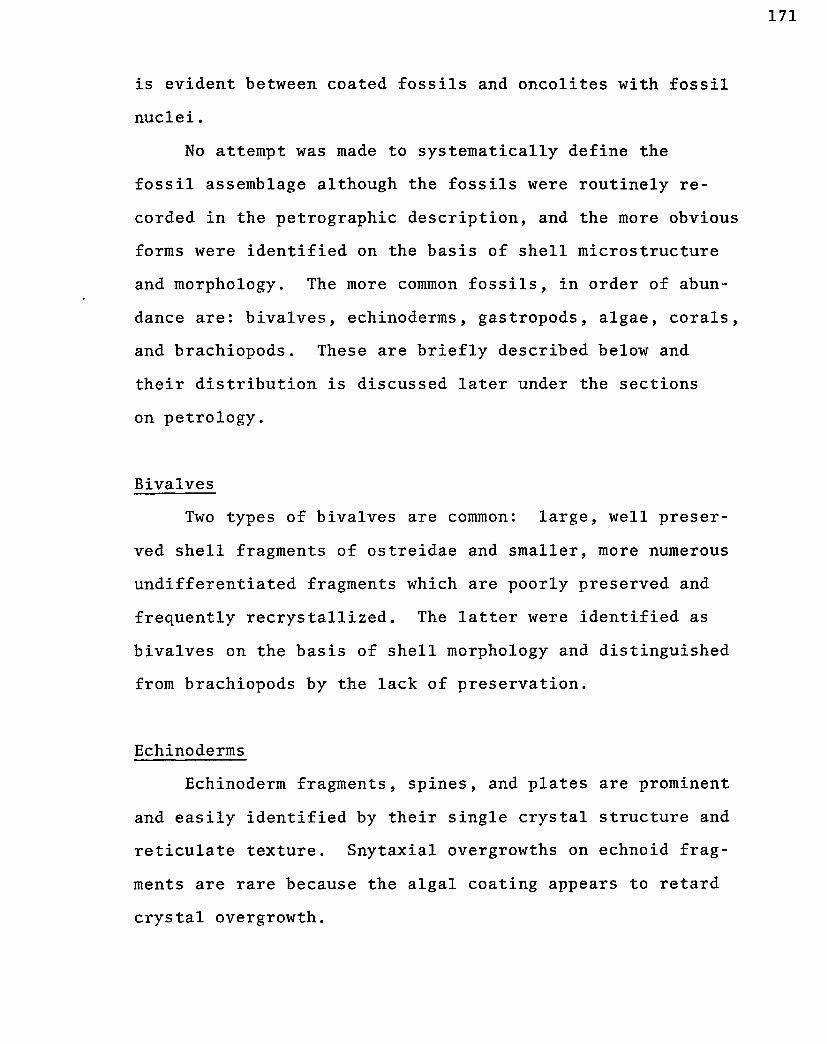
is evident between coated fossils and oncolites with fossil
nuclei.
No attempt was made to systematically define the
fossil assemblage although the fossils were routinely re
corded in the petrographic description, and the more obvious
forms were identified on the basis of shell microstructure
and morphology. The more common fossils, in order of abun
dance are: bivalves, echinoderms, gastropods, algae, corals,
and brachiopods. These are briefly described below and
their distribution is discussed later under the sections
on petrology.
Bivalves
Two types of bivalves are common: large, well preser
ved shell fragments of ostreidae and smaller, more numerous
undifferentiated fragments which are poorly preserved and
frequently recrystallized. The latter were identified as
bivalves on the basis of shell morphology and distinguished
from brachiopods by the lack of preservation.
Echinoderms
Echinoderm fragments, spines, and plates are prominent
and easily identified by their single crystal structure and
reticulate texture. Snytaxial overgrowths on echnoid frag
ments are rare because the algal coating appears to retard
crystal overgrowth.

Gastropods
High spired gastropods are completely recrystallized
to a calcite mosiac and the wall structure is never pre
served. These were identified by shell morphology and are
frequently found forming the nucleus of oncolites.
Calcareous Algae
Both red algae and calcareous green algae are rela
tively abundant in the upper member of the Smackover For
mation. The red algae are represented by solenoporaceae
which usually form small nodular masses. In thin section,
the solenoporaceae appear as long radiating cells separated
by transverse poorly defined partitions. Other algae,
tentatively identified as belonging to the family Codiaceae
(green algae) are poorly preserved and are present as thin
plates in which the structure is completely recrystallized.
In isolated specimens, features suggestive of cells arrange
perpendicular to the walls were noted, but the principle
criteria for identification is the plate-like shape and
irregular surface. Another type, although minor, has a
spherical shape and consists of irregularly spaced tubes
with microcrystalline carbonate material separating the
tubes. This form was also tentatively identified as
codiacean algae.
Corals
The corals occur as free-lying fragments and are

exclusively colonial. Only the peripheral edge of the
coral is preserved and the central mass is completely re-
crystallized to a calcite mosaic. In some of the larger
fragments, the central mass is replaced by anhydrite. In
rare occurrences where the coralites are preserved, a six
fold symmetry of septa is evident and the corals are con
sidered to be scleractinian corals.
Brachiopods
Two kinds of brachiopods were identified: a small
well preserved thin-shell form with punctate wall structure,
identified as terabratulids, and a larger unidentified form
which has an impunctate shell. The latter form was iden
tified as a brachiopod on the basis of the fine, inclined
prismatic microstructure (Majewski, 1969).

APPENDIX A
METHODS OF PETROGRAPHIC ANALYSIS
A5. Description and Origin of Anhydrite
Anhydrite is a common constituent throughout the
Smackover and Buckner Formations, and to a lesser extent
in the Norphlet Formation. Individual anhydrite crystals
occur in a variety of fabrics, the three most significant
being: 1) lenticular anhydrite, 2) elongated anhydrite
laths, and 3) felty anhydrite crystals in polycrystalline
nodules. The lenticular anhydrite and felty anhydrite
fabrics are thought to be formed under conditions which
were controlled by the initial depositional environment
(early diagenetic), whereas the lath-shaped anhydrite is
thought to be formed during a later stage of diagenesis.
Lenticular Anhydrite
This variety of anhydrite is lens-shaped and usually
occurs as small single crystals, 0.5 to 1.0mm in length
(Figure H E ) . In cross-section, the anhydrite crystals
have a characteristic "spindle" shape with no preferred
orientation relative to bedding. The crystals are generally
devoid of inclusions, and commonly appear as clear crystals
with sharp smooth boundaries. Lenticular anhydrite is
174

essentially restricted to the laminated micrite facies of
the lower member of the Smackover Formation and only rare
possible occurrences of lenticular anhydrite were noted
elsewhere in the section. The distribution of lenticular
anhydrite in the laminated micrite is variable with some
zones having a higher concentration than others. However
within any one zone, the crystals are uniformly spaced and
do not appear to form distinct clusters of crystals.
The lenticular anhydrite in the Smackover Formation
is thought to be anhydrite pseudomorphic after gypsum.
The lens-shaped habit is typical of primary gypsum, and
lenticular gypsum has been reported from modern intertidal
and supratidal environments by numerous authors (Masson,
1955; Kinsman, 1969; Davies, 1970). In the intertidal and
supratidal environments, evaporation of surface waters
causes interstitial pore-fluid concentration and direct
precipitation of evaporite minerals. According to Kinsman,
1969, the "lensoid" gypsum crystals are precipitated within
the host sediments and are emplaced by physical displacement
of the host grains. In ancient rocks, crystal habits var
iously described as "bladed" (Kerr and Thompson, 1963) ,
"lens-shaped" (West, 1964), and "lenticular" (Carozzi and
Textoris, 1967) have been inferred to be pseudomorphic
after primary gypsum. This interpretation appears to be
reasonable as the lenticular shape is described as one of
the common shapes of primary gypsum (Dana's Textbook of
Mineralogy, 4th edition, 1966) which crystalizes in the

monoclinic system. By contrast, anhydrite which crystal
lizes in the orthothombic system has a rectangular shape,
without curved crystal faces. It should be noted that in
the case of the Smackover lenticular anhydrite, it could
not be definitely established whether the anhydrite directly
"replaced" gypsum, or that the primary gypsum was dissolved
leaving lenticular molds which were later filled by anhy
drite .
Elongated Anhydrite Laths
This variety of anhydrite has an elongated lath-like
habit (Figure 21F) with crystal faces which are parallel
to well developed rectangular cleavage planes. The anhy
drite laths are typically larger than the lenticular anhy
drite, and frequently measure several milimeters in length.
Also, the anhydrite laths rarely occur as single crystals
and the usual form is a random, parallel, or radiating
cluster of crystals. Commonly, the crystals contain in
clusions (poikiloblastic) of dolomite and other host-rock
impurities. Unlike the other varieties of anhydrite (len
ticular and felty nodules), the lath-shaped anhydrite does
not appear to be closely related to specific lithofacies
units and occurs throughout much of the Smackover and
Buckner sections.
The lath-shaped anhydrite is thought to be a primary
mineral, that is, not derived by replacement of a pre
existing gypsum crystal. Two modes of origin are evident:

1) anhydrite laths replacing calcite, and 2) anhydrite
laths precipitated in open spaces. However, where the
anhydrite crystals are free of inclusions, the exact mode
of origin is frequently indeterminant. The replacement
anhydrite apparently replaces only calcite because in
rocks with both calcite and dolomite, the calcite can be
seen in various stages of being replaced whereas the dolo
mite is unaffected. As a result of this preferential re
placement, dolomite inclusions are typical of the anhy
drite laths (poikiloblastic). Where the anhydrite has
replaced calcite that is relatively free of impurities
(such as calcspar cement), the resulting crystals cannot
be distinguished from pore filling anhydrite cement.
Similarly where anhydrite laths occupy a former allochem
site that is enclosed in a dolomite matrix, it cannot be
determined with certainty if the allochem was replaced by
anhydrite or that the allochem was first dissolved and the
resulting mold was later filled with precipitated anhydrite
With both replacement anhydrite and precipitated anhydrite,
it is probable that the occurrence of lath-shaped anhy
drite was not related to conditions at the time of de
position of the host-rock material, but rather was formed
during a later diagenetic stage.
Felty Anhydrite in Polycrystalline Nodules
Small irregular lamellae of anhydrite which are inter-
grown into a felted network of crystals has come to be

178
known as felty anhydrite (Carozzi, 1960). Individual
crystals are rarely greater than 0.2mm in length, and have
a length to width ratio of approximately five to one. The
felty crystals occur as crystal aggregates which are orga
nized into roughly spherical nodules ("Marocells" of West,
1965) . The crystals show a tendency toward parallelism
of the long axis and frequently occur as swirls of sub-
parallel crystals near the center of the nodule. Near the
outer boundary, the crystals are uniformly oriented with
the long axis parallel to the outer surface. Larger crys
tals probably representing recrystallized anhydrite are
occasionally present and these usually contain relic tex
ture of the smaller felty crystals. The anhydrite nodules
are noticeably free of any impurities such as dolomite or
detrital grains.
The nodules are of irregular tuberous shape and range
from 1mm to several cm in size. They may occur closely
packed forming an anhydrite mosaic (Figure 26A), or as
sparse nodules "floating" in a carbonate matrix. In the
anhydrite mosaics, the boundaries between nodules are out
lined by darker seams of interstitial material, usually
dolomite. Where the host-rock is stratified, the bedding
planes are deflected by the nodule, indicating that the
nodule grew by accretion in soft sediment and mechani
cally displaced the primary sediment.
The felty anhydrite nodules occur in the Norphlet,
Smackover, and Buckner Formations. In the Buckner

Formation, the anhydrites are a major constituent where they
occur in a matrix of aphanocrystalline to very finely crys
talline dolomite. In the upper member of the Smackover
Formation, small beds of nodular anhydrite in dolomite are
occasionally interbedded with oolite rocks. In the Norphlet
Formation, a few scattered small nodules were found em
bedded in red mudstones, siltstones, and sandstones.
The anhydrite nodules are thought to be formed under
supratidal conditions, by evaporative concentration of pore
fluids. The nodules appear to have grown by accretion in
soft sediment near the sediment/air interface under condi
tions similar to those forming today in the Trucial Coast
(Shearman, 1966; Kinsman, 1969). Evidence for this inter
pretation is cited in the section "Depositional Environ
ments of the Lower Member of the Buckner Formation." In
the recent literature, controversy has focused on the
question of whether the anhydrite is primary or formed as
a replacement of primary gypsum. Holliday (1968) working
on the Spitsbergen deposits suggested that the lath-shaped
anhydrite crystals in nodular anhydrite represents primary
anhydrite. West (see discussion of Holliday's article in
Holliday, 1968) expressed the opposing view that the anhy
drite laths are a replacement of primary gypsum based on
evidence from the Purbeck Beds in Sussex. No new informa
tion is offered on the problem of diagenesis of the felty
anhydrite nodules in this study. However, by visual com
parison with published photomicrographs, the felty anhydrite

180
nodules of the Buckner and Smackover Formations appear to
be more like the epigenetic felty anhydrite of Carozzi
(1960), and least like the "lath-shaped" anhydrite nodules
of Holliday, 1968. Regardless of the explicit diagenetic
history of the felty anhydrite (primary vs. secondary-),
it is evident that the nodules formed in soft sediment
prior to lithification and are therefore important to the
analysis of paleodepositional environments.

APPENDIX B
LITHOFACIES - WELL CONTROL
Bl Norphlet Formation, Lower Member
Black Shale Facies
Drill Cuttings
Chevron #1 - Hand (Watts Creek)
Getty #1 - Masonite 17-13 (E. Nancy)
Getty #1 - Masonite 14-4 (Nancy)
Harris #1 - Evans 4-4 (WC/Sec. 4, 1N-15E)
Red Siltstone Facies
Conventional Cores
Shell #1 - Johnston (Goodwater)
Drill Cuttings
Shell #1 - Johnston (Goodwater)
Shell #1 - Ulmer (Goodwater)
Getty #1 - Masonite 17-13 (East Nancy)
Getty #1 - Masonite 14-4 (Nancy)
Exchange #1 - Evans 35-1 (North Shubuta)
Chevron #1 - Hand (Watts Creek)
Getty #1 - Creek (Pachuta Creek)
Harris #1 - Evans 4-4 (WC/Sec. 4, 1N-15E)
Exchange #1 - Bufkin 6-7 (WC/Sec. 6, 2N-15E)
Harris #1 - Moore 10-12 (WC/Sec. 10, 3N-14E)
181

APPENDIX B
LITHOFACIES - WELL CONTROL
B2 Norphlet Formation, Upper Member
Quartz Sandstone Facies
Conventional Cores
Shell #1 - Johnston (Goodwater)
Exchange #1 - Evans 35-1 (North Shubuta)
Chevron #1 - Hand (Watts Creek)
Getty #1 - Masonite 18-8 (East Nancy)
Getty #1 - Allen 20-7 (East Nancy)
Drill Cuttings
Shell #1 - Johnston (Goodwater)
Shell #1 - Ulmer (Goodwater)
Getty #1 - Masonite 17-13 (East Nancy)
Getty #1 - Masonite 14-4 (Nancy)
Exchange #1 - Evans 35-1 (North Shubuta)
Chevron #1 - Hand (Watts Creek)
Getty #1 - Creek (Pachuta Creek Field)
Harris #1 - Evans 4-4 (WC/Sec. 4, 1N-15E)
Exchange #1 - Bufkin 6-7 (WC/Sec. 6, 2N-15E)
Harris #1 - Moore 10-12 (WC/Sec. 10, 3N-14E)
182

APPENDIX B
LITHOFACIES - WELL CONTROL
B3 Smackover Formation, Lower Member
Laminated Dolomite Facies
Conventional Cores
Getty #1 - Allen 20-7 (East Nancy)
Getty #1 - Masonite 18-8 (East Nancy)
Drill Cuttings
Getty #1 - Masonite 17-13 (East Nancy)
Getty #1 - Masonite 14-4 (Nancy)
Chevron #1 - Hand (Watts Creek)
Harris #1 - Evans 4-4 (WC/Sec. 4, 1N-15E)
Exchange #1 - Bufkin 6-7 (WC/Sec. 6, 2N-15E)
Mottled Dolomite Facies
Conventional Cores
Getty #1 - R. Williams 18-9 (East Nancy)
Getty #1 - Collins Coleman 18-15 (East Nancy)
Getty #1 - Allen 20-3 (East Nancy)
Drill Cuttings
Not identified in drill cuttings
183
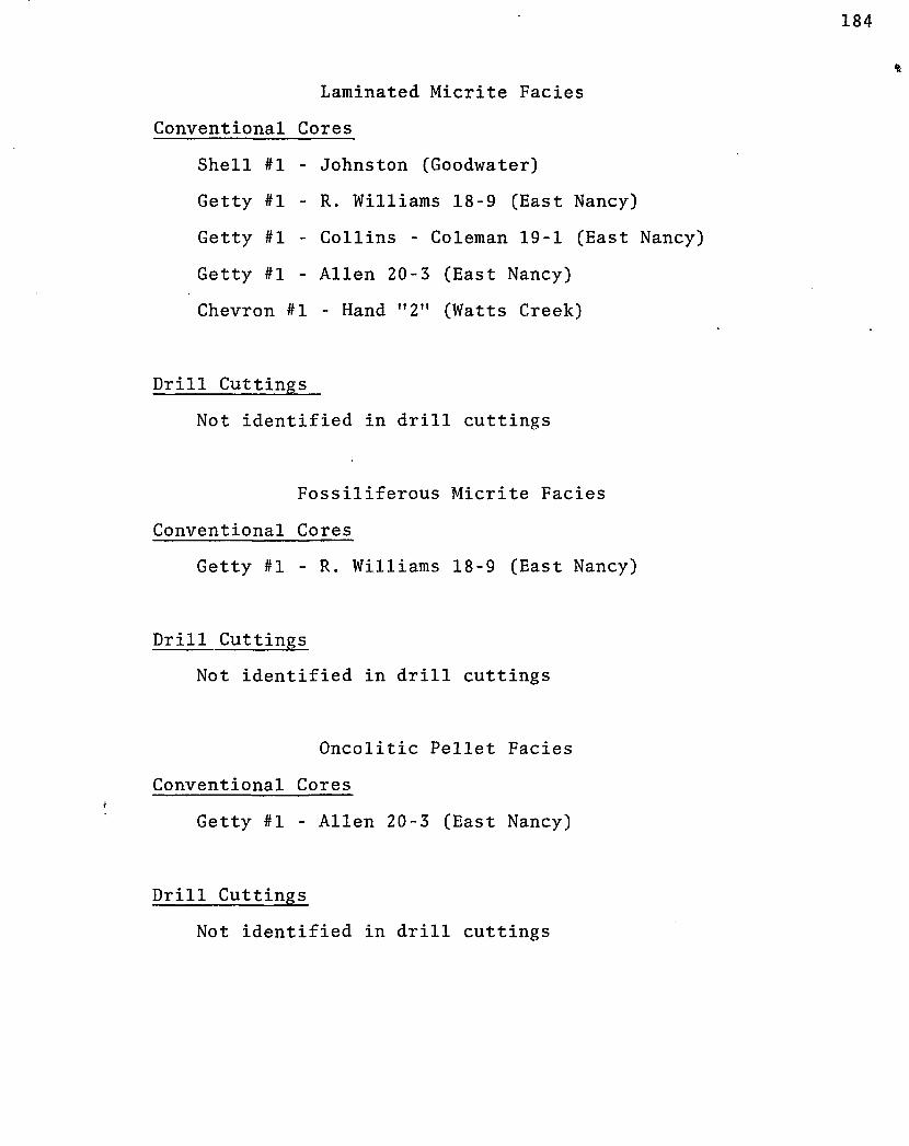
184
Laminated Micrite Facies
Conventional Cores
Shell #1 - Johnston (Goodwater)
Getty #1 - R. Williams 18-9 (East Nancy)
Getty #1 - Collins - Coleman 19-1 (East Nancy)
Getty #1 - Allen 20-3 (East Nancy)
Chevron #1 - Hand "2" (Watts Creek)
Drill Cuttings
Not identified in drill cuttings
Fossiliferous Micrite Facies
Conventional Cores
Getty #1 - R. Williams 18-9 (East Nancy)
Drill Cuttings
Not identified in drill cuttings
Oncolitic Pellet Facies
Conventional Cores
Getty #1 - Allen 20-3 (East Nancy)
Drill Cuttings
Not identified in drill cuttings

APPENDIX B
LITHOFACIES - WELL CONTROL
B4 Smackover Formation, Upper Member
Pelletoidal Micrite Facies
Drill Cuttings
Shell #1 - Johnston (Goodwater)
Shell #1 - Ulmer (Goodwater)
Shell #2 - Johnston (Goodwater)
Shell #1 - Masonite (Goodwater)
Shell #1 - McCarty (Goodwater)
Getty #1 - Masonite 17-13 (East Nancy)
Getty #1 - Masonite 14-4 (Nancy)
Exchange #1 - Evans 35-1 (Nancy)
Chevron #1 - Hand "2" (Watts Creek)
Harris #1 - Evans 4-4 (WC/Sec. 4, IN 1-15E)
Exchange #1 - Bufkin 6-7 (WC/Sec. 6, 2N-15E)
Harris #1 - Moore 10-12 (WC/Sec. 10, 3N-14E)
Superficial Oomicrite Facies
Conventional Cores
Shell #1 - Thomas (Goodwater)
Drill Cuttings
Shell #1 - Johnston (Goodwater)
Shell #2 - Johnston (Goodwater)
Shell #1 - Masonite (Goodwater)
185

Shell #1 - Ulmer (Goodwater)
Shell #1 - Ruter (Goodwater)
Shell #1 - McCarty (Goodwater)
Getty #1 - Masonite 17-13 (East Nancy)
Getty #1 - Masonite 14-4 (Nancy)
Chevron #1 - Hand "2" (Watts Creek)
Exchange #1 - Evans 35-1 (North Shubuta)
Harris #1 - Evans 4-4 (WC/Sec. 4, 1N-15E)
Pelmicrite Facies
Conventional Cores
Shell #1 - Johnston (Goodwater)
Shell #1 - Thomas (Goodwater)
Drill Cuttings
Shell #1 - Johnston (Goodwater)
Shell #2 - Johnston
Shell #3 - Johnston
Shell #1 - Masonite
Shell #1 - Ulmer
Shell #1 - Ruter
Shell #1 - McCarty
Oolite Facies (Goodwater Field)
Conventional Cores
Shell #1 - Ruter
Shell #1 - Ulmer

Shell #1 - Johnston
Drill Cuttings
Shell
Shell
Shell
Shell
Shell
Shell
Shell
Shell
#1 -
#2 -
#1 -
#2 -
#1 -
#2 -
#2 -
#3 -
Johnston
Johnston
Masonite
Masonite
Ulmer
Ulmer
Thomas
Thomas
Oolite Facies (East Nancy Field)
Conventional Cores
Getty #1 - Coleman 18-15
Betty #1 - Masonite 18-8
Getty #1 - Masonite 17-13
Getty #1 - Allen 20-4
Getty #1 - Allen 20-7
Getty #1 - Masonite 20-10
Drill Cuttings
Getty #1 Masonite 17-13
06"lite Facies (Harmony Field)
Conventional Cores
Dunbar #1 - M. A. Kirkland 29-1

188
Masonite #1 - Kirkland 20-6
Mosbacher #1 - Board of Supervisors 16-13
Oolite Facies (Nancy Field)
Conventional Cores
Getty #1 - Masonite 14-4
Drill Cuttings
Getty #1 - Masonite 14-4
Oolite Facies (Pachuta Creek Field)
Conventional Cores
Shell #1 - Evans 26-6
Oolite Facies (Wildcat Wells)
Conventional Cores
Exchange #1 - Evans 35-1
Drill Cuttings
Harris #1 - Evans 4-4
Oncolitic Superficial Oolite Facies
Conventional Cores
Getty #1 - Coleman 18-15 (East Nancy)
Getty #1 - Masonite 18-18 (East Nancy)
Getty #1 - Masonite 17-13 (East Nancy)
Getty #1 - Allen 20-7 (East Nancy)

189
Getty #1 - Allen 20-10 (East Nancy)
Shell #1 - Evans 26-6 (Pachuta Creek)
Mosbacher #1 - Board of Supervisors 16-13 (Harmony)
Drill Cuttings
Harris #1 - Evans 4-4 (WC/Sec. 4, 1N-15E)
Getty #1 - Masonite 14-4 (Nancy)
06lite-Quartz Dolomite Facies
Conventional Cores
Getty #1 Coleman 18-15 (East Nancy)
Getty #1 - Masonite 18-8 (East Nancy)
Getty #1 - Masonite 17-13 (East Nancy)
Getty #1 - Allen 20-4 (East Nancy)
Getty #1 - Allen 20-7 (East Nancy)
Getty #1 - Masonite 17-13 (East Nancy)
Getty #1 - Masonite 14-4 (Nancy)
Dunbar #1-A - Masonite 29-1 (Harmony)
Masonite #1 - Kirkland 20-6 (Harmony)
Mosbacher #1 - Board of Supervisors 16-13 (Harmony)
Harris #1 - Moore 10-12 (WC/Sec. 10 3N-14E)
Drill Cuttings
Harris #1 - Evans 4-4 (WC/Sec. 4, 1N-15E)
Exchange #1 - Bufkin 6-7 (WC/Sec. 6, 2N-15E)

APPENDIX B
LITHOFACIES - WELL CONTROL
B5 Buckner Formation, Lower Member
Conventional Cores
Shell #1 - Johnston (Goodwater)
Getty #1 - Masonite 14-4 (Nancy)
Getty #1 - Coleman 18-15 (East Nancy)
Dunbar #1-A - M. Kirkland (Harmony)
Mosbacher #1 - Board of Supervisors 16-13 (Harmony)
Drill Cuttings
Shell #1 - Johnston (Goodwater)
Getty #1 - Masonite 14-4 (Nancy)
Getty #1 - Masonite 17-13 (East Nancy)
Harris #1 - Evans 4-4 (WC/Sec. 4, 1N-15E)
Exchange #1 - Bufkin 6-7 (WC/Sec. 6, 2N-15E)
Harris #1 - Moore 10-12 (WC/Sec. 10, 3N-14E)
190

APPENDIX C
DETAILED PETROLOGY OF QUARTZ SANDSTONE FACIES,
NORPHLET FORMATION
Quartz is the most abundant grain type and consists
principally of quartz crystals with nonundulabory extinc
tion. The grains are roughly equant in shape and range in
size from fine to medium sand. Grain boundaries at points
of contact usually show only slight penetration, and conse
quently the grains are rather loosely packed. Chert grains
of the micro-crystalline quartz variety are always present
to some degree and are typically better rounded than the
associated quartz grains.
The next most abundant grain type is feldspar and in
cludes both potassium feldspar and plagioclase feldspar.
Many of the feldspar crystals are highly altered, but others
appear fresh and commonly exhibit overgrowths of cement in
optical continuity with the detrital grain. The highly
altered grains are deformed and in some cases they are
difficult to distinguish from detrital matrix material.
Detrital dolomite (Figure 4D) is present throughout
the Upper Member and occasionally make up as much as ten
percent of the grain content. The dolomite occurs as large
single crystals and less commonly as polycrystalline aggre
gates. The single crystals are frequently zoned, but it is
usually difficult to determine if the zoning is inherited
or represents an authigenic overgrowth.
191

Rock fragments seldom account for more than ten percent
of the grain content of the sandstones and are the least
abundant of the major grain types. These are usually com
posed of finely crystalline micaceous material which is simi
lar to some of the phyllitic shale fragments observed at the
bottom of the Sun #1 Board of Supervisors (WC/Sec. 16, 3N-15E) .
These rock fragments may represent low grade metamorphic frag
ments eroded from the adjacent highland.
The most common types of accessory minerals are micas
and opaques. The micas are essentially restricted to the
red sandstone subfacies where they occur as relatively large
crystals (0.100 - 0.150mm) oriented parallel to bedding. The
opaque minerals are found throughout the sequence and are al
ways more rounded than the associated quartz. In incident
light, some of the opaque grains appear to be altered to
hematite (probable magnetite) and others appear to be altered
to leucoxene (probable ilmenite).
Matrix
The matrix material of the grey sandstone consists of
sericite, probable clay minerals, minute quartz grains, and
possibly feldspar grains. The present composition of the
matrix is thought to be the result of diagenetic alterations
of an original silt-clay detritus and is herein referred to
as detrital matrix. In the red sandstone, the origin of the
hematitic interstitial material is more problematic. The
matrix appears to consist of hematite, sericite, very small

dolomite crystals, and possibly clay minerals. As T. B.
Walker (1967) has pointed out, hematite is possibly a dia-
genetic alteration product of Fe-bearing minerals including
both framework grains and detrital matrix. In the red sand
stone subfacies, hematite alteration typically precludes any
distinction between rock fragments, opaque grains, and detrir
tal matrix. Also primary hematite cement in the form of
translucent or opaque minerals would also be difficult to
distinguish from the hematite alteration products.
Cement
Cements are relatively rare in the Upper Norphlet beds
and only small amounts of hematite, anhydrite, and dolomite
were noted. The interstitial hematite in the red sandstone
subfacies may represent either a primary precipitate or a
replacement product. It occurs as stain coating both frame
work grains and detrital matrix, but may also be present as
void-filling cement. Anhydrite cement occurs throughout
the sequence, but is most abundant at the top of the upper
unit (Figure 4E). The crystals are large and appear to show
a preference for growing from one side of the interstitial
void, as each void space is usually filled by a single crys
tal. Anhydrite crystals are not equally distributed through
out a thin section but occur as local patches of cement each
consisting of several crystals. Dolomite is less common and
occurs as overgrowths in optical continuity with the detri
tal dolomite nucleus and as small bladed crystals sparcely

decimiated throughout the thin section.
Hartman (1968) reported halite cement from the Norphlet
Formation in Pelahatchie Field, Rankin County, Mississippi.
In an effort to detect halite cement, several thin sections
were made using oil instead of water in the preparation pro
cess. Although none was observed, it is recognized that
halite could possibly be dissolved in the coring process
because of the high porosity and permeability of these rocks.

APPENDIX D
TSOPACH VALUES
Field/Well Name
Goodwater Shell Shell Shell Shell Shell
IT #1 #2 #1 #1
East Nancy Getty #1-Getty #1-Getty #1 Getty #1-Getty #1-Getty #1-Getty #1-Getty #1-Getty #1-
Field McCarty Johnston Johnston-Thomas Ulmer
Fie ld •Masonite 17-13 •Harper 17-5 •Masonite 17-12 Allen 17-14 •Masonite 18-8 Allen 20-3 Allen 20-7 Masonite 20-10 C.Coleman 19-1
Nancy Field Justiss-Mears #l-Masonite
11-8 Placid #1-Arledge 11-10 Getty #l-Masonite 14-4
Prairie Branch Field
Norphl Lower
NR 64 NR NR NR
125 •NR NR NR NR NR NR NR NR
NR NR 86
* NC -NR -
no correlation not reached
Fault - probable
et Upper
+ 100 75
NR + 200 NR
285 NR NR NR NR NR NR NR NR
NR NR 320
faulted
[ i
section
Smackover Lower
560 545 537 593 403
374 303 369 357 362 405 370 393 391Est.
466 477 463
Upper
400 420 372 347 448
404 426 410 445 442 388 430 389 454
479 436 483
Pan Am #C-1 Masonite
Watts Creek Field Chevron #1-McCoy Chevron #1-Hand
North Shubuta Field Harris #1 Blair 34-1 Exchange #1-Evans 35-1
Harmony Field Mosbacher #1 Bd. of Supv.
16-13 Mosbacher #l-McRae 21-12 Dunbar #A-1 Kirkland 29-1
60
NR 160
130 180
50 60
30
+ 160 340
Fault 260
0 10
450
224 273
Fault 315
NR NC 335
412
676 Fault?
Fault 356
353 NC 368
195

Field/Well Name
Pachuta Shell
Creek Field #l-Britton 22-1
Mosbacher #l-Moore 22-7 Shell #l-McCarty 26-10 Getty #1 Crook 15-16 Mosbacher #1-Gibbs
Wilcat Wells 9-5
6-7
Pruet #l-Goodwin (Sec 5/1N-14E)
Shell #1-Shanks 10-7 (Sec 10/1N-15E)
Shell #l-Newton 15-1 (Sec 15/1N-15E)
Harris #1-Evans 4-4 (Sec 4/1N-15E)
Vanghey #l-McClendon (Sec 30/2N-15E)
Exchange #1-Evans (Sec 6/2N-15E)
Brandon #l-Taylor 4-14 (Sec 4/2N-15E)
Shell #1-Freeman 10-10 (Sec 10/2N-14E)
Pan Am #l-Masonite B-l (Sec 33/3N-15E)
Sun #1-Bd. o£ Supv. (Sec 16/3N-15E)
Harris #l-Moore 10-12 (Sec 10/3N-14E)
Cox
Norphlet Lower Upper
55 49 65 55
+ 100
30
88
100
110
60
+ 25
+ 50
70
NR
?
50
0 0 0 0 0
0
35
170
180
65
45
0
0
NR
?
30
Smackover Lower Upper
Fault 471 418 416 NC
440
350
348
401
300
288
292
427
NR
NC
370
411 431 420
Fault NC
390
630
613
425
381
427
404
Fault?
NR
NC
250

VITA
Calvin Lee Badon was graduated from the University of
Southwestern Louisiana with a B.S. in Geology in 1958. For
three years, he worked for Geophysical Service, Inc. as an
exploration geophysicist. From 1961 to 1963, he attended
the University of Kansas, receiving the M.S. degree in
Geology. During the period 1963 to 1967, he was employed
as a petroleum geologist by the Kerr-McGee Corporation in
Amarillo, Texas, and New Orleans, Louisiana. In 1967, he
enrolled at Louisiana State University as a Ph.D candidate.
197

EXAMINATION AND THESIS REPORT
Candidate: C a l v i n Lee Badon
Major Field: G e o l o g y
Title of Thesis: P e t r o l o g y o f t h e N o r p h l e t a n d Smackover F o r m a t i o n s ( J u r a s s i c ) ; C l a r k e C o u n t y , M i s s i s s i p p i .
Approved:
Dean of the Graduate School
EXAMINING COMMITTEE:
\J>{w &• J^uAXy^
C- o. X-/.
Date of Examination:
March 2 8 , 1973
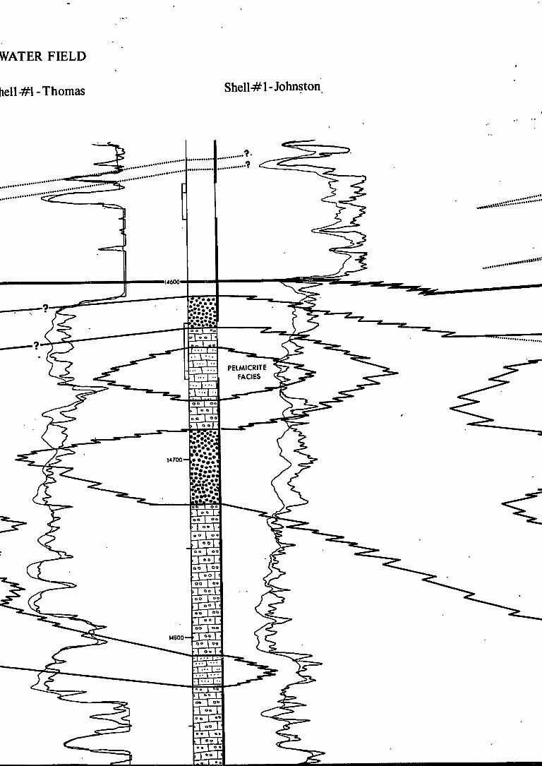
WATER FIELD
dell-#1-Thomas Shell-#1 -Johnston

EAST NANCY FIELD
Getty#l - Masonite 17-13 Getty #1 - Masonite 18|
- » • « « '

y#l-Masonite 18-8
Blaine Dunbar •; Marguerite Kirkla

HARMONY FIELD
Blaine Dunbar#1-A larguerite Kirkland 29-1
Mosbacher#l -Board of Supervisors 16-13
•••rattJo-H
S3-
12400
ma wmimit"
12S00H
12600H
T '"J." . • • • • • I V " * •••• '
Nodular Anl
Dolomite
OOLITE7QUARTZ DOLOMITE FACIES

Exchange#l - Bufkin 6 -7 Section 6, 2N-15E
Nodular Anhydrite in
Dolomite Matrix
Jga E g
12300
""•"«... XJ~*A
fTT4 £^
"•«.,
12400-
12SO0+H
»tf
PEUETOtDAl MfCRITE

Harris#l-Moore 10-12 Section 10,3N-14E
DEEP INDUCTION
CURVC
LATEROLOG
CURVE
T 2 N
PACHUTA CRE
NANCY
PRAIRIE
BRANCH

Stratigraphic Cross-Section UPPER; MEMBER,
SMACKOVER FORMATION
Keyjo
Dual Induction Log
(Data sources, curves, and scale) , 0 1.0
14050
Conventional Core—-•-
EXPLANATION
Resistivity ohms m'/m
100 2000
M100
\ Depth from derrick floor
LITHOFACIES
"ZX^~i
m OOLITE-QUARTZ
DOLOMITE FACIES
OOLITE FACIES
ONCOLITIC SUPERFICIAL OOLITE FACIES
o 1 o o j c o o | o «
- 1 — 1 . 1 — J •i
I - - - H
SUPERFICIAL OOMICRITE FACIES
PELMICRITE FACIES'
PELLETOIDAL MICRITE FACIES
LITHOLOGY
E9
m uzzn
Micrite
Pelmicrite
Pelletoidal Micrite
Dolomite
| § | | j Quartz Sand
Composite Grains
3 a a Intraclasts
m Dense Oneolites

14700-
14900—
,
.
.
ISOOO—
T7T . . . , . . . • 1 - 1 . . . 1 . . .
. • 1 ••• 1
-£-L^-• 1 • -T ... | .. • I - * ! .!. 1 .. • - !-T
| -1 0 0 | c .0 1 o 0 1 1 0 . \o 00 1 00 1 1 0 . | o > • I - O |
| 0 0 | o
• 1 •? 1 J_OO_j0
,0 |"T1 | 0 0 | 0
'• 1 •• 1 1 OO | . »o | ao 1 J c ^ J e >o| «o ] | 0 0 1 0 >e | 0 * \
| 0 0 | 0
>•> ( OO |
L?°To >o 1 o« [
H^r • 1 • 1
• 1 • • I I ] • 1 • . 1 - 1 r- l ; • 1 • 1
• 1 • • 1 • 1 1 • 1 . • 1 . 1 1 • 1 • • 1 • 1 r • 1 • • 1 • r 1 • 1 ; • 1 • r 1 • 1 •
rM ^r^T U-U-; 1 •• 1; ', 1 • 1
; -, . •.
1 ', , • ",
••
; •,
# . 1 •
^ ' r
*^m
^*-^

>\ • • <h
I380O-H
,13900J
ffl—
OO I 00
" > I Q«
•v"r^-
••'f<«i
LUL EZ3
r "n !r5
E I
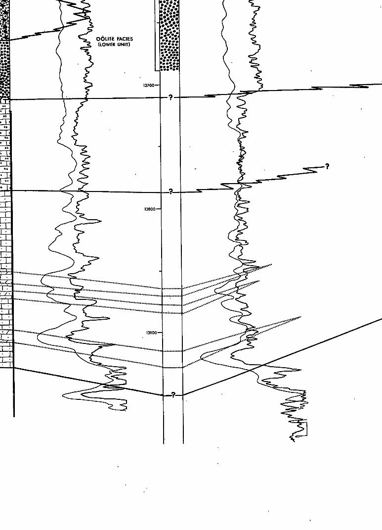
•••I
a
E &
T '
t*7Z75ZM*,
OOLITE FACIES (LOWER UNIT)
13700—H
• • • < » • • • ••• .WW
13B00H
13900 H
h *•'
••' »•'
W +
..,!•-•
*.••••


12400 —i
125004
3 f&oo

..,1-
PELIETOIDAI MICRITE FACIES •

1
*
T
N
PACHUTA CREEK
» • •
• • • • • • • • •
• * • • • • • • • •
. • • •
.• • •
NANCY
» • * • • •
• . . • • .
• * .
PRAIRIE
BRANCH
/
V \
HARMONY \ \ noiMciuir n\ r
Bd. of SUDV. 16-1) 1
•f. • / •
yi * • * **JiDunb4t «1-A „ I N . XirkUnd
/ ""'
/ '
/ / §
! / i
. / EAST NANCY / / c a t t y «1
*£Ah. .oni t« 18-8
• V\ c t t y .1 l ^ H a . o n i t . 17-1)
' ' / • ' •
/ • •
/
/
• * " ' • •
• • / GOODWATER
• A***^— Johmton £ Sh.ll iZjS • . J Thau. "*>^. A 7
• Phell ». \ Ulnwr • w
0 3000 dl!
RBW
INDEX MAP
I
i£ Po"o'2ic
p
0
, c
T - H -
•I •••! ... |..
• 1 • 1 • 1
#
M 0 " o o o« o ° o o o o,? o ° f t°-, o o„oo

14)00 J I \ Depth from
derrick f loor LITHOFACIES
z^C~i OOLITE QUARTZ DOLOMITE FACIES
OOLITE FACIES
ONCOLITIC SUPERFICIAL OdLITE FACIES
LITHOLOGY
x=c
s ' oo o° ' o o o ' ° °o°o
Micrito
Felmicrite
Pelleloidal Micrite
Dolomite
Oolites
Superficial Oolites
SUPERFICIAL OOMICRITE FACIES
PELMICRITE FACES'
PELLETOIDAL MICRITE FACIES
Quartz Sand
l?e»£5£ Composite Grains
a ci3 a Intraclasts
| »
a S» CL © ffl
i
Dense Oncolites
Spongy Oncolites
Fossils
• ^ Nodular Anhydrite
BOUNDARY LINE EXPLANATION
i ^ ^ " " " " ^ Formation Boundary
^ — — — Facies Boundary
•' Lithologic Boundary
Local Erosion Surface
PLATE m

ib*r
NANCY
PRAIRIE
BRANCH
EAST NANCY I otty »1
monit* 16-6 G«tty HI
^Masonlt* 17-13
Shell \t Ttiamas
• . / GOODWATER • JXShmU »1
AjP*—* jnhn«ton
• Shall •« Ul*«r •
INDEX MAP
„ I
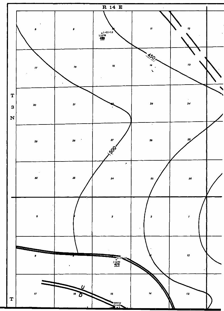
R 14 E

R 15 E
7
IB
h 30
3t
1 +1-6-7 I1300S
bMt
7
16
6
IT
Bd
]
V ^ 20
^ * ^ — -
29 ^ * ^
^ r 32
5 /
""R862
12S0B 1\
a
16
Sun of Supv. • 1
1196 •MC
21
Pan Am 33 ^^ Masonite ^ ^
• B - l ^ 12304 ^ ^
4 1
1-4-14 ^ S " * i
12678 M4
9 ^
-1 \
A l - l / -13
10
16
22
21
34
3
V 10 \
/ /
11
14
All lad Prod
11412
NC
23
26
35
2
11
\
1 •
12
13
24
25
36
1
12
13
T
3
N
T


R 9 W

/
CLARKE COUNTY, MISS. Isopachous Map
LOWER MEMBER BUCKNER FORMATION
Map includes uuly wells t»hjch penetrated Smachovcr interval
Isopach Interval 5 0 Date January 1,1971
Interpretation by Calvin L Badon
12
WELL SYMBOLS
• Oil Well
• Dry Hole
© Discovery Well
1 -20-7 Well Nime
Total Depth
Isopach Value
NoCouelation
Log Not Available
FAULT SYMBOLS
12S/-12600 Fault Throw
14360
ttc
Fault Cut Point
Normal Fault
--•^— Inferred Normal Fault " Xi
FEET 5000 •se)
R 8 W
PLATE IV


R 15 E


R 9 W

R 8 W
RATE V

SHELL#1-JOHNSTON 5-!ftN-8W
GETTY#l-MASONI 17-1N-15E
14200-H
14300-
14300 H
[
13100
I3200H
13300'
13400-1
13500-H
?y«M v " "X. . . .
X
. . -«:••• h'.
; / ; •
, .w '• 13600 -I . . • " • • « " . .
A -.if.
•••.v.
'•••»• fl
V * " ,.1*""
K:'... •f.:v..... 13700
Pelmicrite Faciei
14900—f
15000—1
IZI
POO oooo]
*
Superficial Ofimicrile Faciei oo I
13800-
Pelletoidal Mierite Faciei 13900-
JO.R
>o / Oo
132 IHI
1 3
e -P=l
• I - ' -
..••*"

VIASONITE 17-13 -1N-15E '" " .
HARRIS#1-EVANS 14-4 4-1N-15E
DUNBAR* 1-A-29-21

#1-A-M.KIRKLAND 29-2N-15E
EXCHANGE #1^BUFKIN 6-7 6-2N-15E

HARRIS #1-MOORE 10-12 10-3N-14E
LATER0L0G CURVE

Reg Stratigraphic
NORPHLET-SMA* FORN
EXPl Key to
Dual Induction Log
(Data sources, curves, and scale) i.o
uo?o
Conventional Core——
Drill cuttings
uioo -I \ Depth from
derrick floor LI
I -i~-^Z. Nodular Anhydrite in
c
1
Dolomite Matrix
c o a E
• 1 • 1 • 1 • 1 ' T
1 « 1 OO | o *
1 " I
o
Pellatoidal Micrite Facies
Suparficial Oomfcrite Facias
Pelmicrite Facies
^ l5J52?a _

Regional Stratigraphic Cross-Section
NORPHLET -SMACKOVER-BUCKNER FORMATION
EXPLANATION Key to
Dual Induction Log
(Data sources, curves, and scale) Resistivity ohms m'/m
Conventional Core •
Drill cuttings
U100 -
\ Depth from derrick floor
2000
LATEROLOG CURVE
LITHOFACIES
er F
orm
e Bu
ckn
i 'Y 1 a oo | 00
u.
over
Pelleloidal Micrite Facies
Superficial Oom'rcrite Facies
Pelmicrite Faciei
Nodular Anhydrite in
Dolomite Matrix I* • > > o O -X
—J u a E
I 1 /
I I
' s s / /
Dolomitic Micrite
Laminated Dolomite
Faciei
Black Shale Faciei
S. =•=-- - - Red Siltitone Faciei

WBOO
Pelmicrite Faciei
I4900H
TD


UiU*.:

tL. , '•rrVfc'rttVlT ,J7.;.-:,T-,-.p^-.:....-vAji-.^ . > , . I L . I » Y « - ^ - . - • . • • . . • » . - -
Oolite Quarli Oolomila
Facial
'•«*:.,
• rme* MJCKNF.R FORMATION
> - . . J SMACKOVtK r O R M A I l O N
..•A"*
™:::..;t,.~-• > 11700
. . : « • • • •
rir--
Pelletordal M ic r i t * Facial
11900
fcF
IT' U — I — T - J U p p p f Mambar"
lowar Member
IJOOOH
mooH
\ SMACKOVER FORMATION?
:^^J;MTrORPHUTFORMATION
••:M\fy:\\ Upper Mambar ^J^
| c ^ = - ' - | Lowar Mambar
5 = ^ 3 NORPHIET FORMATION
"rtT * -I O U A N N SALT

Drill c
UNO •
\ Dtplh Irom derrick Hoar
\m i
I fTyTI O
8
E
a
Nodular AnhyrJrila M
Dolomil* Matrix
Matoidal Micrira <
Suparliciol Oomwrit* I
P»lmieril» Facias
Oncolilic Superficial
Oolite--Quartz Dole Facia.
INDEX M A P

14)00 •
\ Dapth from darnel floor
UTHOFACIES
E
3
- ^ 7 ^ Z - | Nodutor Anhydrila in
r " " " . ^ l Dolomita M a l m
o o E
fT t i • r
1 •• !
f±T
m 2 |. . . . \
Pallatoidal Micrita Facial
Suoarliool Oomtcnta Fociai
Palmicrila Fociai
Colila Facial
Oncolihc Suparhciol Oolita Facial
Oolita-Quartz Oolomila Foaai
• 1 5 P
n " T /
/ s / /
Dolomilic Micrila
lominolad Oolomila Fociat
Block Shala Facial
Rad Siltitona Facial
Quortx Sondttona Fociai
BOUNDARV LINE EXPLANATION
• — « — — Formation Boundary
—_> — — Mambar Boundary
Fociat Boundary
PLATE VI