Embed Size (px)
Citation preview

© ISO 2014
Petroleum products — Determination of knock characteristics of motor fuels — Research methodProduits pétroliers — Détermination des caractéristiques antidétonantes des carburants pour moteurs — Méthode de recherche
INTERNATIONAL STANDARD
ISO5164
Fourth edition2014-06-01
Reference numberISO 5164:2014(E)
ISO 5164:2014(E)
ii © ISO 2014 – All rights reserved
COPYRIGHT PROTECTED DOCUMENT
© ISO 2014All rights reserved. Unless otherwise specified, no part of this publication may be reproduced or utilized otherwise in any form or by any means, electronic or mechanical, including photocopying, or posting on the internet or an intranet, without prior written permission. Permission can be requested from either ISO at the address below or ISO’s member body in the country of the requester.
ISO copyright officeCase postale 56 • CH-1211 Geneva 20Tel. + 41 22 749 01 11Fax + 41 22 749 09 47E-mail [email protected] www.iso.org
Published in Switzerland

ISO 5164:2014(E)
© ISO 2014 – All rights reserved iii
Contents Page
Foreword ..........................................................................................................................................................................................................................................vIntroduction ................................................................................................................................................................................................................................vi1 Scope ................................................................................................................................................................................................................................. 12 Normative references ...................................................................................................................................................................................... 13 Termsanddefinitions ..................................................................................................................................................................................... 14 Principle ........................................................................................................................................................................................................................ 35 Reagents and reference materials ..................................................................................................................................................... 36 Apparatus ..................................................................................................................................................................................................................... 57 Sampling and sample preparation .................................................................................................................................................... 68 Basic engine and instrument settings and standard operating conditions ............................................ 6
8.1 Installation of engine equipment and instrumentation ...................................................................................... 68.2 Engine speed ............................................................................................................................................................................................. 68.3 Valve timing ............................................................................................................................................................................................... 78.4 Valve lift ......................................................................................................................................................................................................... 78.5 Intake valve shroud ............................................................................................................................................................................. 78.6 Carburettor venturi ............................................................................................................................................................................. 78.7 Direction of engine rotation ........................................................................................................................................................ 78.8 Valve clearances ..................................................................................................................................................................................... 78.9 Oil pressure ................................................................................................................................................................................................ 78.10 Oil temperature ...................................................................................................................................................................................... 88.11 Cylinder jacket coolant temperature ................................................................................................................................... 88.12 Intake air temperature ..................................................................................................................................................................... 88.13 Intake air humidity .............................................................................................................................................................................. 88.14 Cylinder jacket coolant level........................................................................................................................................................ 88.15 Engine crankcase lubricating oil level................................................................................................................................. 98.16 Crankcase internal pressure ........................................................................................................................................................ 98.17 Exhaust back-pressure ..................................................................................................................................................................... 98.18 Exhaust and crankcase breather system resonance ............................................................................................... 98.19 Belt tension ................................................................................................................................................................................................ 98.20 Rocker arm carrier support basic setting ........................................................................................................................ 98.21 Rocker arm carrier basic setting ............................................................................................................................................. 98.22 Rocker arm and push rod length basic settings ......................................................................................................... 98.23 Basic spark setting ............................................................................................................................................................................ 108.24 Basic ignition timer control arm setting ........................................................................................................................ 108.25 Basic ignition timer transducer to rotor vane gap setting .............................................................................108.26 Spark-plug gap ...................................................................................................................................................................................... 108.27 Basic cylinder height setting .................................................................................................................................................... 108.28 Fuel-air ratio .......................................................................................................................................................................................... 118.29 Carburettor cooling .......................................................................................................................................................................... 128.30 Knockmeter reading limits ........................................................................................................................................................ 128.31 Detonation meter spread and time constant settings ........................................................................................12
9 Enginecalibrationandqualification ............................................................................................................................................129.1 General ........................................................................................................................................................................................................ 129.2 Engine fit-for-use qualification .............................................................................................................................................. 129.3 Fit-for-use procedure in the 87,1 RON to 100,0 RON range .........................................................................139.4 Fit-for-use procedure below 87,1 RON and above 100,0 RON ...................................................................149.5 Checking performance on check fuels ............................................................................................................................. 14
10 Procedure..................................................................................................................................................................................................................1510.1 General ........................................................................................................................................................................................................ 1510.2 Start-up ....................................................................................................................................................................................................... 15

ISO 5164:2014(E)
iv © ISO 2014 – All rights reserved
10.3 Calibration ............................................................................................................................................................................................... 1510.4 Sample fuel .............................................................................................................................................................................................. 1610.5 Primary reference fuel No. 1 .................................................................................................................................................... 1610.6 Primary reference fuel No. 2 .................................................................................................................................................... 1710.7 Additional measurement readings ..................................................................................................................................... 1710.8 Special instructions for ratings above 100,0 RON .................................................................................................17
11 Calculation ...............................................................................................................................................................................................................1812 Expression of results .....................................................................................................................................................................................1813 Precision ....................................................................................................................................................................................................................19
13.1 General ........................................................................................................................................................................................................ 1913.2 Repeatability, r ..................................................................................................................................................................................... 1913.3 Reproducibility, R ............................................................................................................................................................................... 1913.4 Precision for ratings at barometric pressures below 94,6 kPa ..................................................................1913.5 Precision for fuels containing 15% to 25% (V/V) ethanol ............................................................................20
14 Test report ................................................................................................................................................................................................................20Annex A (informative) Test variable characteristics ........................................................................................................................21Bibliography .............................................................................................................................................................................................................................24

ISO 5164:2014(E)
Foreword
ISO (the International Organization for Standardization) is a worldwide federation of national standards bodies (ISO member bodies). The work of preparing International Standards is normally carried out through ISO technical committees. Each member body interested in a subject for which a technical committee has been established has the right to be represented on that committee. International organizations, governmental and non-governmental, in liaison with ISO, also take part in the work. ISO collaborates closely with the International Electrotechnical Commission (IEC) on all matters of electrotechnical standardization.
The procedures used to develop this document and those intended for its further maintenance are described in the ISO/IEC Directives, Part 1. In particular the different approval criteria needed for the different types of ISO documents should be noted. This document was drafted in accordance with the editorial rules of the ISO/IEC Directives, Part 2. www.iso.org/directives
Attention is drawn to the possibility that some of the elements of this document may be the subject of patent rights. ISO shall not be held responsible for identifying any or all such patent rights. Details of any patent rights identified during the development of the document will be in the Introduction and/or on the ISO list of patent declarations received. www.iso.org/patents
Any trade name used in this document is information given for the convenience of users and does not constitute an endorsement.
For an explanation on the meaning of ISO specific terms and expressions related to conformity assessment, as well as information about ISO’s adherence to the WTO principles in the Technical Barriers to Trade (TBT), see the following URL: Foreword - Supplementary information
The committee responsible for this document is ISO/TC 28, Petroleum products and lubricants.
This fourth edition cancels and replaces the third edition (ISO 5164:2005). Besides improving the understanding of some of the procedures, the main revision lays in the introduction of the so-called digital detonation meter. The revision includes allowances both measurement systems:
a) the knock measurement system based on analogue technology, and
b) the XCP digital technology used in the digital detonation meter.
© ISO 2014 – All rights reserved v
ISO 5164:2014(E)
Introduction
The purpose of this International Standard is to accord ISO status to a test procedure that is already used in a standardized form all over the world. The procedure in question is published by ASTM International as Standard Test Method D 2699-12.
By publishing this International Standard, ISO recognizes that this method is used in its original text in many member countries and that the standard equipment and many of the accessories and materials required for the method are obtainable only from specific manufacturers or suppliers. To carry out the procedure in every detail requires reference to annexes and appendices of ASTM D 2699-12. The annexes detail the specific equipment and instrumentation required, the critical component settings and adjustments, and include the working tables of referenced settings. The appendices provide background and additional insight about auxiliary equipment, operational techniques and the concepts relative to proper maintenance of the engine and instrumentation items.
The accumulated motor fuel data relating to knock characteristics determined in many countries has, for many years, been based on the use of the CFR engine and the ASTM octane test methods. Accepted worldwide, petroleum industry octane number requirements for motor fuels are defined by the research method and associated CFR F-1 Octane Rating Unit1), which emphasizes the need for this method and test equipment to be standardized. The initiation of studies to use a different engine for ISO purposes has therefore been considered an unnecessary duplication of effort.
For these reasons, it has been considered desirable by ISO Technical Committee 28, Petroleum products and lubricants, to adopt the ASTM D 2699 standard procedures. However, this International Standard refers to annexes and appendices of ASTM D 2699 without change because of their extensive detail. These annexes and appendices are not included in this International Standard because they are available from ASTM International.
Due to identified component obsolescence issues, the original, analogue control panel has been replaced by the manufacturer by new digital panel as of 2011. Service parts availability for the analogue system will be phased out in the future. Research work was executed by ASTM International[5] to check whether there was statistically observable systemic bias between the 501C and the new digital knock measurement system.
With respect to precision ISO and ASTM technical committees concluded that there was numerically comparable precision for repeatability between the 501C and new panel knock measurement systems, and no statistically observable difference for reproducibility between the 501C and new panel knock measurement systems. This means that the new CFR octane panel could be included in the test method.
1) The sole manufacturer of the Model CFR F-1 Octane Rating Unit is Waukesha Engine, Dresser Waukesha, Inc., 1000 West St. Paul Avenue, Waukesha, WI 53188, USA.
vi © ISO 2014 – All rights reserved

Petroleum products — Determination of knock characteristics of motor fuels — Research methodWARNING — The use of this International Standard may involve hazardous materials, operations and equipment. This International Standard does not purport to address of the safety problems associated with its use. It is the responsibility of the user of this International Standard to establish appropriate safety and health practices and determine the applicability of regulatory limitations prior to use.
1 Scope
This International Standard establishes the rating of liquid spark-ignition engine fuel in terms of an arbitrary scale of octane numbers using a standard single-cylinder, four-stroke cycle, variable compression ratio, carburetted, CFR engine operated at constant speed. Research octane number (RON) provides a measure of the knock characteristics of motor fuels in automotive engines under mild conditions of operation.
This International Standard is applicable for the entire scale range from 0 RON to 120 RON, but the working range is 40 RON to 120 RON. Typical motor fuel testing is in the range of 88 RON to 101 RON.
This International Standard is applicable for oxygenate-containing fuels containing up to 4,0 % (m/m) oxygen and for gasoline containing up to 25 %(V/V) ethanol.
NOTE 1 Although 25 % (V/V) of ethanol corresponds to approximately 9 % (m/m) oxygen, full applicability of this test method for that oxygen range has only been checked for gasoline type of fuels.
NOTE 2 Work is under way to check the possibility to use the method up to and including 85 %(V/V) ethanol.
NOTE 3 This International Standard specifies operating conditions in SI units but engine measurements may be specified in inch-pound units because these were the units used in the manufacture of the equipment, and thus some references in this International Standard include these units in parenthesis.
NOTE 4 For the purposes of this standard, the terms “% (m/m)” and “% (V/V)” are used to represent the mass fraction, µ, and the volume fraction, φ, of a material respectively.
2 Normative references
The following documents, in whole or in part, are normatively referenced in this document and are indispensable for its application. For dated references, only the edition cited applies. For undated references, the latest edition of the referenced document (including any amendments) applies.
ISO 3170, Petroleum liquids — Manual sampling
ISO 3171, Petroleum liquids — Automatic pipeline sampling
ISO 3696, Water for analytical laboratory use — Specification and test methods
ISO 4787, Laboratory glassware — Volumetric instruments — Methods for testing of capacity and for use
ASTM D2699-12, Standard Test Method for Research Octane Number of Spark-Ignition Engine Fuel
3 Termsanddefinitions
For the purposes of this document, the following terms and definitions apply.
INTERNATIONAL STANDARD ISO 5164:2014(E)
© ISO 2014 – All rights reserved 1

ISO 5164:2014(E)
3.1accepted reference valueARVvalue that serves as an agreed-upon reference for comparison, and which is derived as: a theoretical or established value, based on scientific principles, an assigned or certified value, based on experimental work of some national or international organization, or a consensus or certified value, based on collaborative experimental work under the auspices of a scientific or engineering group
3.2check fuelfuel of selected characteristics that has a RON accepted reference value determined by round-robin testing by multiple engines in different locations
3.3cylinder heightrelative vertical position of the CFR engine cylinder with respect to the piston at top dead center (t.d.c.) or the top machined surface of the crankcase
3.4dial indicator readingnumerical indication of cylinder height, indexed to a basic setting when the engine is motored with the compression ratio set to produce a specified compression pressure
Note 1 to entry: The dial indicator reading is expressed in thousandths of an inch.
3.5digital counter readingnumerical indication of cylinder height, indexed to a basic setting when the engine is motored with the compression ratio set to produce a specified compression pressure
3.6detonation meterknock signal conditioning instrumentation that accepts the electrical signal from the detonation pickup and produces an output signal for display
Note 1 to entry: The meter is either analogue or digital.
3.7detonation pickupmagnetostrictive-type transducer that threads into the engine cylinder to sense combustion-chamber pressure and provide an electrical signal proportional to the rate-of-change of that cylinder pressure
3.8firingengine operation with fuel and ignition
3.9fuel-air ratio for maximum knock intensityproportion of fuel to air that produces the highest knock intensity for each fuel
3.10guide tabletabulation of the specific relationship between cylinder height and octane number for the CFR engine operated at standard knock intensity and a specified barometric pressure
3.11knockabnormal combustion, often producing an audible sound, caused by auto-ignition of the air-fuel mixture
2 © ISO 2014 – All rights reserved

ISO 5164:2014(E)
3.12knock intensitymeasure of engine knock
3.13knockmeterindicating meter with a division scale that displays the knock intensity signal from the detonation meter
Note 1 to entry: The meter is either analogue or digital.
3.14motoringengine operation without fuel and with the ignition shut off
3.15research octane numberRONnumerical rating of knock resistance for a fuel obtained by comparing its knock intensity with that of primary reference fuels of known research octane number when tested in a standardized CFR engine operating under conditions specified in this document
3.16oxygenateoxygen-containing organic compound, such as various alcohols or ethers, used as a fuel or fuel supplement
3.17primary reference fuelPRF2,2,4-trimethylpentane (iso-octane), n-heptane, volumetrically proportioned mixtures of iso-octane with n-heptane, or blends of tetraethyl lead in iso-octane, which define the octane number scale
3.18spreadsensitivity of the detonation meter expressed in knockmeter divisions per octane number
3.19toluene standardization fuelTSFvolumetrically proportioned blend that has RON accepted reference value and specified rating tolerances
4 Principle
A sample fuel, operating in a CFR engine at the fuel-air ratio that maximizes its knock, is compared to primary reference fuel blends to determine that blend which, when operated at the fuel-air ratio that maximizes its knock, would result in both fuels producing the same standard knock intensity when tested at the same engine compression ratio. The volumetric composition of the primary reference fuel blend defines both its octane number and that of the sample fuel.
5 Reagents and reference materials
5.1 Cylinder-jacket coolant, consisting of water conforming to grade 3 of ISO 3696. Water shall be used in the cylinder jacket for laboratory locations where the resultant boiling temperature is 100 °C ± 1,5 °C (212 °F ± 3 °F). Water with commercial glycol-based antifreeze added in sufficient quantity to meet the boiling temperature requirement shall be used when laboratory altitude dictates.
A commercial multi-functional water treatment material should be used in the coolant to minimize corrosion and mineral scale that can alter heat transfer and rating results.
© ISO 2014 – All rights reserved 3

ISO 5164:2014(E)
5.2 Carburettor coolant, if required (see 8.29), consisting of water or a water-antifreeze mixture, chilled sufficiently to prevent fuel bubbling and excessive vaporization, but neither colder than 0,6 °C nor warmer than 10 °C.
5.3 Engine crankcase-lubricating oil, comprising an SAE 30 viscosity grade oil meeting service classification API SF/CE or better.
It shall contain a detergent additive and have a kinematic viscosity of 9,3 mm2/s to 12,5 mm2/s at 100 °C (212 °F) and a viscosity index of not less than 85. Oils containing viscosity index improvers shall not be used. Multi-grade lubricating oils shall not be used.
5.4 2,2,4-trimethylpentane (iso-octane) primary reference fuel, of minimum purity 99,75 % (V/V), containing no more than 0,10 % (V/V) heptane and no more than 0,5 mg/l lead. This material shall be designated as 100 RON1).
WARNING—iso-Octaneisflammableanditsvapoursareharmful.Vapoursmaycauseflashfire.
5.5 n-Heptane primary reference fuel, of minimum purity 99,75 % (V/V), containing no more than 0,10 % (V/V) isooctane and no more than 0,5 mg/l lead. This material shall be designated as 0 RON2).
WARNING — n-heptaneisflammableanditsvapoursareharmful.Vapoursmaycauseflashfire.
5.6 80-octane primary reference fuel blend, prepared using reference fuel grade iso-octane (5.4) and n-heptane (5.5); this blend shall contain 80 % (V/V) ± 0,1 % (V/V) iso-octane.
NOTE ASTM D 2699–12, Annex A3 (Reference Fuel Blending Tables), provides information for preparation of primary reference fuel blends to specific RON values.
5.7 Tetraethyl lead, dilute, (TEL dilute volume basis), consisting of a solution of aviation mix tetraethyl lead antiknock compound in a hydrocarbon diluent of 70 % (V/V) xylene and 30 % (V/V) n-heptane.
WARNING—Tetraethylleadispoisonousandflammable.Itmaybeharmfulorfatalifinhaled,swallowed,orabsorbedthroughtheskin.Maycauseflashfire.
The anti-knock compound shall contain 18,23 % (m/m) ± 0,05 % (m/m) tetraethyl lead and have a relative density at 15,6 °C/15,6 °C (60 °F/60 °F) of 0,957 to 0,967.
NOTE 1 The typical composition of the compound, excluding the tetraethyl lead, is as follows:
Ethylene dibromide (scavenger): 10,6 % (m/m)
Diluent:
xylene 52,5 % (m/m)
heptane 17,8 % (m/m)
Dye, antioxidant and inerts 0,87 % (m/m)
NOTE 2 Developments within ISO are under way in order to make less use of lead-containing PRFs.
5.8 Primary reference fuel blends for ratings over 100 RON, prepared by adding dilute tetraethyl lead (5.7), in millilitre quantities, to a 400 ml volume of iso-octane (5.4). These blends define the RON scale above 100.
1) PRFSs are commercially available, currently from Chevron Phillips Chemical Company LP., 1301 McKinney, Suite 2130, Houston, TX 77010–3030, USA or Haltermann Products—Werk Hamburg, Zweigniederlassung der DOW Olefinverbund GmbH, Schlengendeich 17, 21107 Hamburg, Germany.
4 © ISO 2014 – All rights reserved

ISO 5164:2014(E)
NOTE ASTM D 2699–12, Annex A3 (Reference Fuel Blending Tables), provides information on the RON values for blends of tetraethyl lead in isooctane.
5.9 Methylbenzene (toluene), reference fuel grade, with a minimum purity of 99,5 % (V/V) as determined by chromatographic analysis, a peroxide number not exceeding 5 mg/kg and a water content not exceeding 200 mg/kg.
Antioxidant treatment should be added by the supplier at a rate suitable for long term stability as empirically determined with the assistance of the antioxidant supplier.
5.10 Check fuels, consisting of in-house typical spark-ignition engine fuels having RON accepted reference values, low volatility and good long-term stability.
6 Apparatus
6.1 Test engine assembly, a CFR octane rating unit consisting of a single-cylinder engine consisting of a standard crankcase, a cylinder/clamping sleeve assembly to provide continuously variable compression ratio adjustable with the engine operating, thermal-siphon recirculating jacket cooling system, a multiple fuel tank system with selector valving to deliver fuel through a single jet passage and carburettor venturi, an intake air system with controlled temperature and humidity equipment, electrical controls, and a suitable exhaust pipe.
The engine flywheel shall be connected by a belt to a special electric power-absorption motor that acts as a motor driver to start the engine and as a means to absorb power at constant speed when combustion is occurring (engine firing).
NOTE Test engine assembly is available from the single source manufacturer, GE Waukesha gas engine, Dresser, Inc., 1000 West St. Paul Avenue, Waukesha, WI 53188, USA. This information is given for the convenience of users of this International Standard but does not constitute an endorsement by ISO of this product.
6.2 Instrumentation, consisting of electronic detonation metering instrumentation, including a detonation pickup and knockmeter to measure and display the intensity of combustion knock, as well as conventional hardware, tubing, fasteners, electrical and electronic items.
NOTE Instrumentation is available from multiple sources. In some cases, selection of specific dimensions or specification criteria are important to achieve proper conditions for the knock testing unit, and these are included in ASTM D2699–12, Appendix X1 when applicable.
6.3 Reference and standardization fuel dispensing equipment, consisting of calibrated burettes or volumetric ware having a capacity of 200 ml to 500 ml and a maximum volumetric tolerance of ±0,2 %.
Calibration shall be verified in accordance with ISO 4787. Burettes shall be outfitted with a delivery valve and delivery tip to accurately control dispensed volumes. The delivery tip shall be of such size and design that shut-off tip discharge does not exceed 0,5 ml. The rate of delivery from the dispensing system shall not exceed 400 ml/min. The installation shall be in such a manner and be supplied with fluids such that all components of each batch or blend are dispensed at the same temperature.
6.4 Gravimetric blending of reference fuels, use of blending systems that allow preparation of the volumetrically-defined blends by gravimetric (mass) measurements based on the density of the individual components is also permitted, provided the system meets the requirement for maximum 0.2 % blending tolerance limits.
Calculate the mass equivalents of the volumetrically-defined blend components from the densities of the individual components at 15,56°C (60°F).
© ISO 2014 – All rights reserved 5

ISO 5164:2014(E)
6.5 Tetraethyl lead (TEL) dispensing equipment, consisting of a calibrated burette, pipette assembly, or other liquid-dispensing apparatus, having a capacity not exceeding 4,0 ml, and a critically controlled tolerance for dispensing dilute TEL into 400 ml batches of iso-octane.
Calibration shall be verified in accordance with ISO 4787.
NOTE ASTM D 2699–12, Appendix X2 (Volumetric Reference Fuel Blending Apparatus and Procedures), provides additional information for application.
6.6 Special maintenance tools, consisting of a number of speciality tools and measuring instruments available for easy, convenient and effective maintenance of the engine and testing equipment.
NOTE Lists and descriptions of these tools and instruments are available from the manufacturers of the engine equipment and those organizations offering engineering and service support for this International Standard.
7 Sampling and sample preparation
7.1 Unless otherwise specified in the commodity specification, samples shall be taken as described in ISO 3170 or ISO 3171 and/or in accordance with the requirements of national regulations for the sampling of the product under test, or an equivalent national standard.
7.2 Cool samples to 2 °C to 10 °C(35 °F to 50 °F) in the container in which they are received and before the container is opened.
7.3 Minimize the sample’s exposure to light before pouring it into the engine carburettor fuel bowl, because of possible sensitivity to light that can affect fuel characteristics. Collect and store samples in an opaque container.
8 Basic engine and instrument settings and standard operating conditions
8.1 Installation of engine equipment and instrumentation
Locate the octane test engine in an area where it will not be affected by certain gases and fumes that may have a measurable effect on the RON test result (see Clause 1).
Installation of the engine and instrumentation requires placement of the engine on a suitable foundation and hook-up of all utilities. Engineering and technical support for this function is required, and the user shall be responsible for complying with all local and national codes and installation requirements. Proper operation of the CFR engine requires assembly of a number of engine components and adjustment of a series of engine variables to prescribed specifications. Some of these settings are established by component specifications, others are established at the time of engine assembly or after overhaul, and still others are engine running conditions that must be observed or determined by the operator during the testing process. Annex A gives further information on the test variable characteristics.
8.2 Engine speed
Engine speed shall be 600 r/min ± 6 r/min when the engine is operating with combustion with a maximum variation of 6 r/min occurring during a rating.
Engine speed when combustion is occurring shall not be more than 3 r/min greater than for motoring without combustion.
6 © ISO 2014 – All rights reserved

ISO 5164:2014(E)
8.3 Valve timing
With the piston at the highest point of travel in the cylinder, set the flywheel pointer mark in alignment with the 0° mark on the flywheel in accordance with the instructions of the manufacturer.
The four-stroke cycle engine uses two crankshaft revolutions for each complete combustion cycle. The two critical valve events are those that occur near top-dead-centre (t.d.c.), i.e. intake valve opening and exhaust valve closing. Intake valve opening shall occur 10,0° ± 2,5° after t.d.c. with closing at 34° after-bottom-dead-centre (a.b.d.c.) on one revolution of the crankshaft and flywheel. Exhaust valve opening shall occur 40° before-bottom-dead-centre (b.b.d.c.) on the second revolution of the crankshaft and flywheel with closing at 15,0° ± 2,5° after t.d.c. on the next revolution of the crankshaft and flywheel.
8.4 Valve lift
Intake and exhaust cam lobe contours, while different in shape, shall have a contour rise of 6,248 mm to 6,350 mm (0,246 in to 0,250 in) from the base circle to the top of the lobe so that the resulting valve lift shall be 6,045 mm ± 0,050 mm (0,238 in ± 0,002 in). See ASTM D 2699-12, Annex A2 (Apparatus Assembly and Setting Instructions), for procedures for measuring valve lift which shall apply for this International Standard.
8.5 Intake valve shroud
The 180° shroud or protrusion directs the incoming fuel-air mixture and increases its turbulence in the combustion chamber. This valve stem is drilled for a pin, which is restrained in a valve guide slot, to prevent the valve from rotating and thus maintain the direction of swirl. The valve shall be assembled in the cylinder, with the pin aligned in the valve guide, so that the shroud is toward the spark plug side of the combustion chamber and the swirl is directed in a counter-clockwise direction if it could be observed from the top of the cylinder.
8.6 Carburettor venturi
The venturi throat size, regardless of ambient barometric pressure, shall be 1,43 cm (9/16 in).
8.7 Direction of engine rotation
The crankshaft, when observed from the front of the engine, rotates in a clockwise direction.
8.8 Valve clearances
With the engine cold prior to being operated, set the clearance between each valve stem and valve rocker half-ball to the following approximate measurements upon assembly, which will typically provide the controlling engine running and hot clearance:
— intake valve: 0,10 mm (0,004 in);
— exhaust valve: 0,36 mm (0,014 in).
These clearances should ensure that both valves have sufficient clearance to cause valve seating during engine warm-up. The adjustable-length valve push rods shall be set so that the valve rocker adjusting screws have adequate travel to permit the final clearance setting. Engine running and hot clearance for both intake and exhaust valves shall be set to 0,200 mm ± 0,025 mm (0,008 in ± 0,001 in) measured under standard operating conditions with the engine running at equilibrium conditions on a 90 RON primary reference fuel.
8.9 Oil pressure
Oil pressure shall be 172 kPa to 207 kPa (25 psi to 30 psi).
© ISO 2014 – All rights reserved 7

ISO 5164:2014(E)
8.10 Oil temperature
Oil temperature shall be 57 °C ± 8 °C (135 °F ± 15 °F), accuracy recommended as with the ASTM 83 °C (83 °F) thermometer.
8.11 Cylinder jacket coolant temperature
Cylinder jacket coolant temperature shall be 100,0 °C ± 1,5 °C (212 °F ± 3 °F), but shall not vary by more than ± 0,5 °C (1 °F) during a rating of either certified reference material or knock intensity.
8.12 Intake air temperature
8.12.1 Set the temperature to 52 °C ± 1 °C during a rating made at a standard barometric pressure of 101,3 kPa (29,92 in Hg). At other barometric pressures, set the temperature to the value listed in Table 1 for that prevailing pressure. If intake air temperature tuning is utilized to qualify the engine as fit-for-use based on the RON value of the appropriate toluene standardization fuel (TSF) blend, the selected temperature shall be within ± 22 °C (40 °F) of the temperature listed in Table 1 for the prevailing barometric pressure. When the intake air temperature is tuned, the temperature selected to provide the RON of the appropriate TSF blend shall be used during that operating period for all ratings in the applicable RON range for that TSF blend. The intake air temperature variation during a rating (tuned or untuned) while KI reading are being taken shall not exceed 1 °C (2 °F).
Table 1 — Intake air temperatures for prevailing barometric pressures
Prevailing barometric pressure kPa (in Hg)
Standard intake air temperature °C (in °F)
104,6 (30,9) 59,4 (139)101,3 (29,92) 52,0 (125,6)
98,2 (29,0) 43,9 (111)94,8 (28,0) 36,1 (97)91,4 (27,0) 27,8 (82)88,0 (26,0) 19,4 (67)
86,3 (25,5) and lower 15,6 (60)
8.12.2 Temperature measurement systems used to establish the Intake Air Temperature in this test method shall exhibit the same temperature indicating characteristics and accuracy as the ASTM 83°C (83°F) thermometer installed at the orifice provided using the manufacturers prescribed fitting.
8.12.3 To ensure the correct temperature is indicated the temperature measurement system shall be installed in accordance with the instructions provided for this specific application.
8.13 Intake air humidity
The water content of the air shall be between 0,003 56 kg per kilogram of dry air and 0,007 12 kg per kilogram of dry air.
8.14 Cylinder jacket coolant level
The coolant level when the engine is running and hot shall be within ± 10 mm of the “LEVEL HOT” mark on the coolant condenser.
NOTE With the engine cold prior to being operated, treated coolant added to the cooling condenser/cylinder jacket to a level just observable in the bottom of the condenser sight glass, will typically provide the controlling engine running and hot operating level.
8 © ISO 2014 – All rights reserved

ISO 5164:2014(E)
8.15 Engine crankcase lubricating oil level
The controlling engine running and hot operating level of the oil in the crankcase shall be approximately mid-position in the crankcase sight glass.
NOTE With the engine cold prior to being operated, oil added to the crankcase so that the level is near the top of the sight glass, will typically provide this condition.
8.16 Crankcase internal pressure
The pressure shall be less than zero (a vacuum) and typically from 25 mm to 150 mm of water less than atmospheric pressure, as measured by a gauge, a pressure sensor or manometer connected to an opening to the inside of the crankcase through a snubber orifice to minimize pulsations. Vacuum shall not exceed 255 mm of water.
8.17 Exhaust back-pressure
The static pressure shall be as low as possible, but shall not create a vacuum nor exceed 255 mm of water differential in excess of atmospheric pressure, as measured by a gauge or manometer connected to an opening in the exhaust surge tank or main exhaust stack through a snubber orifice to minimize pulsations.
8.18 Exhaust and crankcase breather system resonance
The exhaust and crankcase breather piping systems shall have internal volumes and be of such length that gas resonance does not occur.
NOTE ASTM D 2699–12, Appendix X3 (Operating Techniques — Adjustment of Variables), provides a suitable procedure to determine if resonance exists.
8.19 Belt tension
The belts connecting the flywheel to the absorption motor shall be tightened, after initial break-in, so that with the engine stopped, a 2,25 kg mass suspended from one belt half way between the flywheel and the motor pulley, depresses the belt approximately 12,5 mm.
8.20 Rocker arm carrier support basic setting
For exposed valve train applications, each rocker arm carrier support shall be threaded into the cylinder so that the distance between the underside of its fork and the machined top surface of the cylinder is 31 mm (17/32 in). For enclosed valve train applications, each rocker arm carrier support shall be threaded into the cylinder so that the distance between the top machined surface of the valve tray and the underside of the fork is 19 mm (3/4 in).
8.21 Rocker arm carrier basic setting
With the distance between the cylinder and the clamping sleeve at approximately 16 mm (5/8 in), the rocker arm carrier shall be horizontal before tightening the bolts that fasten the long carrier support to the clamping sleeve.
8.22 Rocker arm and push rod length basic settings
With the engine crankshaft and flywheel on t.d.c. on the compression stroke and the rocker arm carriers properly levelled, set the rocker arm adjusting screws at mid-travel and adjust the length of the push rods so the rocker arms are horizontal.
© ISO 2014 – All rights reserved 9

ISO 5164:2014(E)
8.23 Basic spark setting
The basic spark setting shall be 13° before t.d.c., regardless of cylinder height setting.
NOTE The digital timing indicator currently supplied with CFR engine units, or the graduated spark quadrant formerly supplied, should be in proper working order and calibrated so that the time of ignition is correctly displayed with reference to the engine crankshaft.
8.24 Basic ignition timer control arm setting
If present on the engine, disengage the mechanism by loosening the knurled clamping screw on the control arm so that the linkage is ineffective.
8.25 Basic ignition timer transducer to rotor vane gap setting
The basic ignition timer transducer to rotor vane gap setting shall be 0,08 mm to 0,13 mm (0,003 in to 0,005 in).
8.26 Spark-plug gap
The spark-plug (Champion D16, or equivalent) gap shall be 0,51 mm ± 0,13 mm (0,020 in ± 0,005 in).
8.27 Basic cylinder height setting
Operate the engine at typical knocking conditions to ensure it is thoroughly warmed up. Shut down the engine. Check that the ignition is off and that fuel cannot enter the combustion chamber. Install a calibrated compression pressure gauge in the detonation pickup hole of the cylinder. Start and operate the engine under motoring conditions. Adjust the cylinder height to produce the basic compression pressure for the prevailing barometric pressure in accordance with the information shown in Figure 1.
Set the cylinder height indicating devices as follows:
— digital counter reading (uncompensated for barometric pressure) to 930;
— dial indicator reading to 0,352 in.
NOTE It is inappropriate to convert the dial indicator reading into SI units; see Introduction.
See ASTM D 2699-12, Annex A2 (Apparatus Assembly and Setting Instructions), for the detailed procedure for indexing the cylinder height that shall apply for this International Standard.
10 © ISO 2014 – All rights reserved

ISO 5164:2014(E)
KeyX1 barometric pressure, in HgX2 barometric pressure, mm HgY compression pressure, psig
NOTE Basic cylinder height setting:
— digital counter: 930;
— dial indicator: 0,352.
Figure 1 — Actual compression pressure for setting cylinder height2)
8.28 Fuel-air ratio
For all sample fuels and primary reference fuels, the fuel-air ratio (a function of the effective fuel level in the vertical jet of the standard carburettor assembly) shall be adjusted to maximize knock intensity. When the carburettor sight glasses are used as the indication of mixture strength, the maximum knock condition shall occur when the fuel level in the sight glass is between 17,8 mm (0,7 in) and 45,2 mm (1,7 in), a condition that is dependent on selecting the proper carburettor horizontal jet.
The bracketing–dynamic equilibrium procedure requires a falling level reservoir assembly to vary fuel-air ratio at a constant rate from a rich to lean mixture. The cross sectional area of the reservoir determines the rate at which the fuel level falls. Within the range that establishes a fuel level for maximum knock intensity, in the carburettor vertical jet between 17,8 mm (0,7 in) and 45,2 mm (1,7 in) referenced to the
2) Extracted, with permission, from ASTM D 2699.
© ISO 2014 – All rights reserved 11

ISO 5164:2014(E)
centreline of the carburettor venturi, the cross sectional area of the reservoir shall be constant and not less than 3 830 mm2 (5,9 in2).
8.29 Carburettor cooling
Circulate carburettor coolant (5.2) through the coolant exchangers of the carburettor assembly if there is premature vaporization or bubbling in the sight glasses or transparent fuel lines.
NOTE Release of hydrocarbon vapours from the sample fuel can result in uneven engine operation or erratic knock intensity reading and is usually indicated by bubble formation or abnormal fluctuation of the fuel level in the sight glass.
8.30 Knockmeter reading limits
The permissible analogue knockmeter range shall be 20 divisions to 80 divisions to prevent potential nonlinear characteristics that may affect octane ratings.
NOTE Knock intensity is a nonlinear characteristic below 20 and the analogue knockmeter has the potential to be nonlinear above 80.
The operational range on the digital knockmeter shall be from 0 to 999 knock intensity readings and is linear throughout this range
8.31 Detonation meter spread and time constant settings
Optimize spread and time constant settings of the detonation meter commensurate with reasonable knockmeter reading stability.
Experience has shown for digital detonation meters that these variables may be left constant, and default values may be used. The default value for spread on the digital detonation meter may be left at 0, and the default value for the time constant on the digital detonation meter may be left at 25.
In case of using an analogue detonation meter, use the procedure given in ASTM D 2699-12, Annex A2 (Apparatus Assembly and Setting Instructions), to set the analogue detonation meter.
9 Enginecalibrationandqualification
9.1 General
The engine shall be commissioned in a manner such that all settings and operating conditions are at equilibrium and in compliance with basic engine and instrument specifications.
CAUTION — Certain gases and fumes, such as halogenated refrigerants used in air-conditioning equipment, that can be present in the area where the CFR engine is located, can have a measurable effect on the RON rating. Electrical power transient voltage or frequency surges or distortion can affect RON ratings.
Engine warm-up typically requires 1 h to ensure all critical variables are stable. During the final 10 min of this warm-up period the engine should operate at a typical knock intensity level on liquid fuel.
9.2 Enginefit-for-usequalification
9.2.1 The engine shall be qualified as fit-for-use by rating a toluene standardization fuel (TSF) blend for every RON range in which sample fuels are to be rated in accordance with the following:
a) at least once during a 12 h operating period;
b) after an engine has been shut down for more than 2 h;
12 © ISO 2014 – All rights reserved

ISO 5164:2014(E)
c) after an engine has been allowed to operate at non-knocking conditions for more than 2 h;
d) after a change in barometric pressure of more than 0,68 kPa (0,2 in Hg) from that which prevailed at the time of the previous TSF blend rating for a RON range to be used for rating sample fuels.
9.2.2 The bracketing procedure for rating TSF blends shall be carried out using the cylinder height (compensated for barometric pressure) in accordance with the guide table for standard knock intensity for the RON accepted reference value of the TSF blend.
9.2.3 Standard knock intensity shall be determined using the PRF blend whose whole RON is closest to the RON accepted reference value of the TSF blend.
9.2.4 Carburettor cooling shall not be used.
9.3 Fit-for-use procedure in the 87,1 RON to 100,0 RON range
9.3.1 Select the TSF blend(s) listed in Table 2 for the RON range(s) in which sample fuel ratings are to be made during the operating period.
Table 2 — TSF blend RON, untuned rating tolerances, and sample fuel RON range of use
RON of calibrated TSF
blendUntuned rat-ing tolerance
TSF blend composition % (V/V) Use for sample fuel
RON rangeToluene iso-Octane n-Heptane
89,3a ± 0,3 70 0 30 87,1 to 91,593,4a,b ± 0,3 74 0 26 91,2 to 95,396,9a,b ± 0,3 74 5 21 95,0 to 98,599,8b ± 0,3 74 10 16 98,2 to 100,0
a Blends calibrated by the ASTM National Exchange Group in 1986.[[2]]
b Blends calibrated by the TCD93 worldwide programme.[[1]]
9.3.2 Using the standard intake air temperature based on the prevailing barometric pressure, determine the RON of an untuned TSF blend. The engine shall be qualified as fit-for-use if this TSF blend rating is within the untuned rating tolerance specified in Table 2 and intake temperature tuning is not required, although it is permissible if the rating is more than 0,1 RON from the RON accepted reference value of the TSF blend.
It is permissible to start fit-for-use testing for a new operating period using approximately the same intake air temperature tuning adjustment applied for the previous operating period, recognizing that the barometric pressure for the two periods may be slightly different, if both the following conditions are met.
a) The engine standardization during the last operating period required intake air temperature tuning for the last fit-for-use test.
b) Maintenance has not taken place in the period between fit-for-use tests.
9.3.3 An untuned engine that rates a TSF blend outside the untuned RON rating tolerance specified in Table 2 may be temperature-tuned using an intake air temperature that is within ± 22 °C (40 °F) of the standard temperature specified for the prevailing barometric pressure.
NOTE 1 Increasing the temperature decreases the RON. The RON change per intake air temperature degree varies slightly with RON level and is typically larger at higher values.
© ISO 2014 – All rights reserved 13
ISO 5164:2014(E)
NOTE 2 When using an analogue detonation meter, a TSF blend rating change from 0,1 RON to 0,2 RON requires an intake air temperature adjustment of approximately 5,5°C (10°F).
NOTE 3 When using a digital detonation meter, a TSF blend rating change from 0,3 RON to 0,4 RON requires an intake air temperature adjustment of approximately 4,5°C (8°F).
The engine shall be qualified as fit-for-use if the TSF blend rating is within ± 0,1 RON of the RON accepted reference value of the TSF blend as in Table 2. It shall not be used to rate sample fuels, in the applicable RON range for that TSF blend, if it cannot be so qualified. The cause of the inability to rate the TSF blend shall be determined and corrected.
9.4 Fit-for-use procedure below 87,1 RON and above 100,0 RON
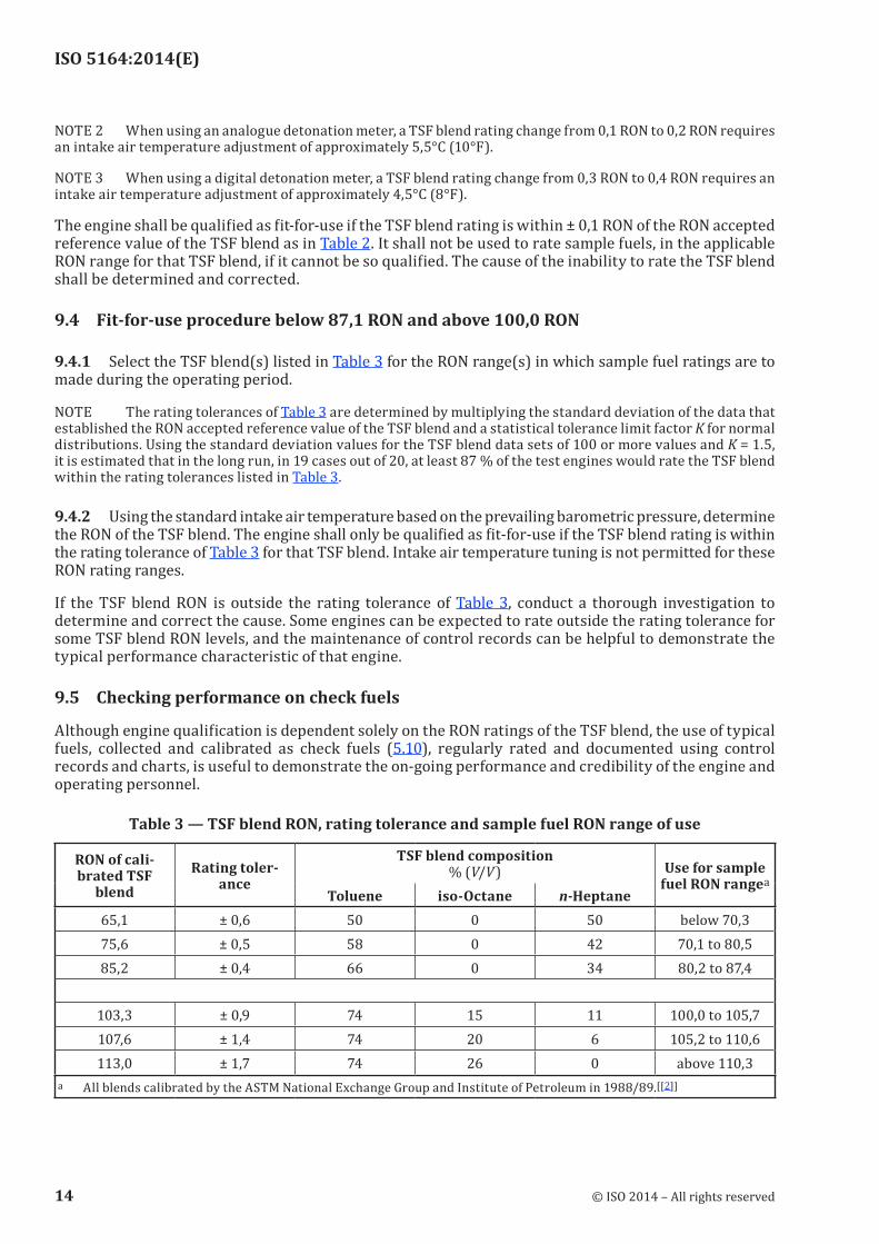
9.4.1 Select the TSF blend(s) listed in Table 3 for the RON range(s) in which sample fuel ratings are to made during the operating period.
NOTE The rating tolerances of Table 3 are determined by multiplying the standard deviation of the data that established the RON accepted reference value of the TSF blend and a statistical tolerance limit factor K for normal distributions. Using the standard deviation values for the TSF blend data sets of 100 or more values and K = 1.5, it is estimated that in the long run, in 19 cases out of 20, at least 87 % of the test engines would rate the TSF blend within the rating tolerances listed in Table 3.
9.4.2 Using the standard intake air temperature based on the prevailing barometric pressure, determine the RON of the TSF blend. The engine shall only be qualified as fit-for-use if the TSF blend rating is within the rating tolerance of Table 3 for that TSF blend. Intake air temperature tuning is not permitted for these RON rating ranges.
If the TSF blend RON is outside the rating tolerance of Table 3, conduct a thorough investigation to determine and correct the cause. Some engines can be expected to rate outside the rating tolerance for some TSF blend RON levels, and the maintenance of control records can be helpful to demonstrate the typical performance characteristic of that engine.
9.5 Checking performance on check fuels
Although engine qualification is dependent solely on the RON ratings of the TSF blend, the use of typical fuels, collected and calibrated as check fuels (5.10), regularly rated and documented using control records and charts, is useful to demonstrate the on-going performance and credibility of the engine and operating personnel.
Table 3 — TSF blend RON, rating tolerance and sample fuel RON range of use
RON of cali-brated TSF
blendRating toler-
ance
TSF blend composition % (V/V) Use for sample
fuel RON rangeaToluene iso-Octane n-Heptane
65,1 ± 0,6 50 0 50 below 70,375,6 ± 0,5 58 0 42 70,1 to 80,585,2 ± 0,4 66 0 34 80,2 to 87,4
103,3 ± 0,9 74 15 11 100,0 to 105,7107,6 ± 1,4 74 20 6 105,2 to 110,6113,0 ± 1,7 74 26 0 above 110,3
a All blends calibrated by the ASTM National Exchange Group and Institute of Petroleum in 1988/89.[[2]]
14 © ISO 2014 – All rights reserved

ISO 5164:2014(E)
10 Procedure
10.1 General
Four specific procedural variations can be used for the determination of RON:
a) Bracketing-equilibrium fuel level;
b) Bracketing-dynamic fuel level;
c) Compression ratio;
d) Bracketing OA.
Only the original procedure A is described in this International Standard. However, all four procedures have equivalent precision in the RON range of typical commercial motor fuel and can be used for ratings in specific RON ranges.
Check that all engine operating conditions are in compliance and equilibrated with the engine running on a typical fuel.
10.2 Start-up
Determine that the engine is fit-for-use. If tuning of the intake air temperature is utilized to qualify the engine, the selected intake air temperature for the RON of the appropriate TSF blend shall be used, during the operating period, to rate every sample fuel in the applicable RON range of use for that TSF blend.
10.3 Calibration
10.3.1 Calibrate the engine and instrumentation to establish standard knock intensity using a PRF blend whose RON is close to that of the sample fuels to be tested.
10.3.2 Set the cylinder height (compensated for barometric pressure) in accordance with the RON value for the PRF selected (given in Annex A4 of ASTM D 2699-12).
10.3.3 Operate the engine utilizing the PRF and vary the fuel-air ratio to establish the setting that maximizes the knockmeter reading.
10.3.4 Adjust the detonation meter controls to produce a knockmeter reading of 50 divisions ± 2 divisions with an optimized spread commensurate with knockmeter stability.
When using the analog knockmeter, check that detonation meter SPREAD is maximized commensurate with satisfactory knockmeter stability.
NOTE Adjustment of the digital detonation meter is not necessary. For analogue detonation meters, guide tables for standard knock intensity at standard barometric pressure listing the cylinder heights for each RON (in tenths) over the range from 40 RON to 120 RON are given in ASTM D 2699–12, Annex A4.4 (Guide Tables of Constant Knock Intensity). To complement these tables, Annex A4.4 also includes a table for compensation of guide table cylinder heights when the barometric pressure is either below or above standard barometric pressure.
10.3.5 If the sample fuel RON is indicated to be higher than 100, standard knock intensity shall be established using one of the isooctane and TEL PRF blends that will bracket the sample fuel. Several trials may be required in order to select the appropriate PRF. In addition, use the PRF blends specific to the RON rating range as specified in Table 4. Adjust the detonation meter settings such that the detonation meter spread is maintained as large as possible, despite knockmeter reading instability.
© ISO 2014 – All rights reserved 15

ISO 5164:2014(E)
10.4 Sample fuel
10.4.1 Introduce the sample fuel to the carburettor, purge the fuel system and, if applicable, the sight glass and float reservoir by opening then closing the sight glass drain valve several times and observe that there are no bubbles in the clear plastic tubing between the float reservoir and the sight glass.
10.4.2 Operate the engine on the sample fuel and check that the fuel system is free of vapour bubbles.
10.4.3 Adjust the cylinder height to result in a mid-scale knockmeter reading.
NOTE For the digital detonation meter, it is not necessary to establish a mid-scale knockmeter reading.
10.4.4 Determine the fuel level for maximum knock intensity. One approach is to first lower the fuel level (float reservoir assembly) and then to raise it in small increments (0,1 sight glass divisions or less) until the knockmeter reading peaks and begins to fall off. Reset the float reservoir to the fuel level that produces the maximum knockmeter reading.
10.4.5 Adjust the fuel-air ratio and determine the maximum knockmeter reading attainable. If necessary, readjust the cylinder height such that the maximum knockmeter reading occurs at 50 divisions ± 2 divisions. No adjustment of the digital detonation meter is necessary.
10.4.6 Record the sample fuel knockmeter reading.
Table 4 — Maximum permissible bracketing PRF RON differences
RON range of sample fuel Permissible PRF blends40 to 72 Maximum permissible RON difference of 4,072 to 80 Maximum permissible RON difference of 2,4
80 to 100 Maximum permissible RON difference of 2,0100,0 to 100,7 Use only 100,0 and 100,7 RON PRF blends.100,7 to 101,3 Use only 100,7 and 101,3 RON PRF blends.101,3 to 102,5 Use only 101,3 and 102,5 RON PRF blends.102,5 to 103,5 Use only 102,5 and 103,5 RON PRF blends.103,5 to 108,6 Use PRF blends with TEL contents 0,053 ml/l (0,2 ml/U.S. gal) apart.108,6 to 115,5 Use PRF blends with TEL contents 0,132 ml/l (0,5 ml/U.S. gal) apart.115,5 to 120,3 Use PRF blends with TEL contents 0,264 ml/l (1,0 ml/U.S. gal) apart.
10.5 Primary reference fuel No. 1
10.5.1 Based on the cylinder height used for the sample fuel, refer to the appropriate guide table (see 10.3.2) and select a PRF that can be expected to have a RON close to that of the sample fuel.
10.5.2 Prepare a fresh batch of the PRF. Operate the engine using this PRF, and check that the fuel system is free of vapour bubbles, if applicable, purge the fuel lines in the same manner as noted for the sample fuel..
10.5.3 Without changing the cylinder height from that used for the sample fuel, adjust the fuel-air ratio and determine the maximum knockmeter reading for the PRF.
10.5.4 Record the PRF knockmeter reading.
16 © ISO 2014 – All rights reserved

ISO 5164:2014(E)
10.6 Primary reference fuel No. 2
10.6.1 Select a second PRF that will meet the maximum permissible bracketing difference requirements specified in Table 4, and that can be expected to cause the knockmeter readings for the two PRF blends to bracket that of the sample fuel.
10.6.2 Prepare a fresh batch of the second PRF. Operate the engine using this PRF, and check that the fuel system is free of vapour bubbles, if applicable, purge the fuel lines in the same manner as noted for the sample fuel.
10.6.3 Without changing the cylinder height from that used for the sample fuel, adjust the fuel-air ratio and determine the maximum knockmeter reading for the PRF.
10.6.4 Record the PRF knockmeter reading.
10.6.5 If the knockmeter reading for the sample fuel is bracketed by those of the PRF blends, continue the test. Otherwise, try additional PRF blends until this requirement is satisfied.
10.7 Additional measurement readings
10.7.1 Without changing the cylinder height, operate the engine on the sample fuel followed by PRF No. 2 (see 10.6), and then PRF No. 1 (see 10.5) to obtain a second series of knockmeter readings. For each fuel, ensure that the fuel-air ratio for maximum knockmeter reading is used and allow operation to reach equilibrium before recording the knockmeter readings.
10.7.2 If in the process of calculating the RON of the sample fuel the first two series of knockmeter readings do not meet the criteria specified in 11.3, obtain a third series of readings on the three fuels.
10.8 Special instructions for ratings above 100,0 RON
10.8.1 Knock characteristics become more erratic and unstable at octane levels above 100 for several reasons. Careful attention to the setting and adjustment of all variables is required to ensure that the rating is representative of the sample fuel quality.
Refer to Table 4 when selecting the PRF blends for sample fuels that rate above 100 RON. Use only the specified PRF pairs for sample fuels that rate in the ranges (100,0 to 100,7), (100,7 to 101,3), (101,3 to 102,5) and (102,5 to 103,5).
10.8.2 If the sample fuel rating will be above 100 RON, it is necessary to establish standard knock intensity using an iso-octane plus TEL PRF blend before sample fuel testing continues. This may require more than one trial to select the appropriate leaded PRF (one of the two that bracket the sample fuel) and proper cylinder height. If the rating is between (100,0 and 100,7) RON, use the iso-octane plus 0,05 ml TEL PRF to establish standard knock intensity. At the higher RON levels, either of the specified leaded PRF blends for the particular RON range may be used for this purpose.
When using the analogue knockmeter, adjust the detonation meter METER READING dial to obtain a knockmeter reading of approximately 50 divisions.
When using the analogue detonation meter, check that detonation meter spread is maintained as large as possible despite the fact that knockmeter readings will vary considerably and make selection of an average reading tedious. No adjustment of the digital detonation meter is necessary.
© ISO 2014 – All rights reserved 17

ISO 5164:2014(E)
11 Calculation
11.1 Calculate the RON of the first series of knockmeter readings by interpolation of their values proportioned to the octane number of the bracketing reference fuels in accordance with Formula (1):
Y YX XX X
YRON,S RON,LRFKI,LRF KI,S
KI,LRF KI,HRFRON,H= +
−−
RRF RON,LRF−( )Y (1)
where
YRON,S is the RON of the sample fuel;
YRON,LRF is the RON of the low reference fuel;
YRON,HRF is the RON of the high reference fuel;
XKI,S is the knockmeter reading of the sample fuel;
XKI,LRF is the knockmeter reading of the low reference fuel;
XKI,HRF is the knockmeter reading of the high reference fuel.
11.2 Calculate the RON of the second series of knockmeter readings.
11.3 The RON based on the averages of the two series of knockmeter readings constitutes a rating if:
a) the difference in the calculated RON values for each of the individual series of knockmeter readings is no greater than 0,3 RON, and
b) the average of the first and the second sample fuel knockmeter readings is between 45 and 55, and
c) the cylinder height (compensated for barometric pressure) used for the rating is within the specified limits from the applicable guide table (digital counter reading = ±20, or a dial indicator reading = ±0,014 in).
Condition b) is not applicable for the digital knockmeter
NOTE It is inappropriate to convert the dial indicator reading into SI units, see Introduction, paragraph 4.
11.4 If either the calculated RON difference or the average knockmeter reading criteria is not met, a third series of knockmeter readings on the sample fuel and reference fuels No. 1, and No. 2, shall be obtained. The second and third series of readings can then constitute a rating if they meet the criteria specified in 11.3.
11.5 If the cylinder height, compensated for barometric pressure, used for the rating is outside the guide table limit, conduct a new rating after readjusting the detonation meter settings to establish the appropriate standard knock intensity using a PRF blend whose RON is close to that of the sample fuel..
12 Expression of results
Report the calculated research octane number in accordance with the requirements of Table 5. When the calculated RON value ends in exactly 5 in the place just beyond that to which it is to be reported, round to the nearest even digit.
EXAMPLE 67,50 and 68,50 would be rounded to 68 as the nearest integer; 93,55 and 93,65 would be rounded to 93,6 as the nearest tenth.
18 © ISO 2014 – All rights reserved

ISO 5164:2014(E)
Table5—Significantdigitsforreportingresearchoctanenumber
Research octane number range
Report to
Below 72,0 nearest integer72,0 to 103,5 nearest tenthAbove 103,5 nearest integer
13 Precision
13.1 General
Both the bracketing-equilibrium fuel level and compression ratio procedures have been widely used for a number of years and the precision data reflect their equivalent performance. The compression ratio procedure [see 10.1 c)] is allowed for ratings between 80 RON and 100 RON for the purposes of this International Standard. The bracketing-dynamic fuel level procedure [see 10.1 b)] was examined for equivalency between 90 RON and 100 RON using four commercial fuels, three TSF blends and eight oxygenate-containing fuels, as detailed in ASTM Research Report RR:D02-1343.[3] The auto-Octane procedure [see 10.1 d)] was found to have the same precision and range as the bracketing equilibrium procedure
Repeatability precision limits for the 90 RON to 100 RON range are based on the ASTM Motor National Exchange Group (NEG) program data from 1983 through 1987 and 1994, during which periods the monthly samples were rated twice on the same day by the same operator on one engine in each of the member laboratories.[4]
Reproducibility precision limits for the 90 RON to 100 RON range are based on the data from the NEG and the Institute of Petroleum monthly exchange programs from 1988 through 1994, as well as those of the Institut Français du Pétrole monthly exchange program from 1991 through 1994.[4] Sample fuels containing oxygenates (alcohols or ethers), in concentrations typical of commercial fuel, were included in these data.
Reproducibility precision limit values above 100 RON are based on ASTM Aviation NEG data as well as a limited amount of data from the Institute of Petroleum and Institut Français du Pétrole exchange programs.[4]
NOTE Precision for medium and high ethanol blend products is under development within ASTM and CEN.
13.2 Repeatability, r
For ratings at barometric pressures of 94,6 kPa (28,0 in of Hg) and higher, the difference between two test results obtained by the same operator with the same apparatus under constant operating conditions on identical test material would in the long run, in the normal and correct operation of the test method, exceed the values given in Table 6 in only one case in 20.
13.3 Reproducibility, R
For ratings at barometric pressures of 94,6 kPa (28,0 in of Hg) and higher, the difference between two single and independent test results obtained by different operators working in different laboratories on identical test material would in the long run, in the normal and correct operation of the test method, exceed the values given in Table 6 in only one case in 20.
13.4 Precision for ratings at barometric pressures below 94,6 kPa
The precision of this test method when performed at barometric pressures of less than 94,6 kPa (28,0 in of Hg) has not been adequately determined. However, reproducibility for the 88,0 RON to 98,0 RON range
© ISO 2014 – All rights reserved 19

ISO 5164:2014(E)
at altitude locations, based on the ASTM Rocky Mountain Regional Group interlaboratory results3), would, in the long run, in the normal operation of the test method, exceed approximately 1,0 RON in only one case in 20.
13.5 Precision for fuels containing 15% to 25% (V/V) ethanol
The repeatability and reproducibility, as defined in clauses 13.2 and 13.3, for fuels containing 15 % (V/V) up to 25 % (V/V) ethanol are as follows:
Repeatability, r = 0,3
Reproducibility, R = 0,8
Table 6 — Research octane number repeatability and reproducibility limits
Average research octane number level
Repeatabilityr
ReproducibilityR
Below 90,0 no current data no current data90,0 to 100,0 0,2 0,7
101,0 no current data 1,0102,0 no current data 1,4103,0 no current data 1,7104 no current data 2,0
> 104 to 108 no current data 3,5
14 Test report
The test report shall contain at least the following information:
a) a reference to this International Standard;
b) the type and complete identification of the product tested;
c) the method used for sampling (see Clause 7)
d) the results of the test (see Clause 12);
e) any deviation, by agreement or otherwise, from the procedures specified;
f) the date of the test.
3) Supporting data (a listing of the data and the analyses used to establish the precision statements) have been filed at ASTM International, PO Box C700, 100 Barr Harbor Drive, West Conshohocken, PA, USA
20 © ISO 2014 – All rights reserved

ISO 5164:2014(E)
Annex A (informative)
Test variable characteristics
A.1 Cylinder height relationship to octane number
Cylinder height, an indication of compression ratio, has a significant effect on fuels and their knocking characteristics. Every fuel has a critical compression ratio at which knock begins to occur. As compression ratio is increased above this critical threshold, the degree of knock, or severity of knock, increases. The Research method of test compares sample fuels to PRF blends at a selected knock level termed standard knock intensity. Guide tables of cylinder height versus RON have been empirically determined using PRF blends. They are based on the concept that the knock intensity at all RON values is constant as detected by the knock measuring instrumentation. Specific guide tables in terms of both digital counter reading and dial indicator reading f are in Annex A4 of ASTM D2699.
A.2 Barometric pressure compensation of cylinder height
RON values determined by this test method are referenced to standard barometric pressure of 760 mmHg (29,92 in Hg). Changes in barometric pressure affect the level of knock because the density of the air consumed by the engine is altered. To compensate for a prevailing barometric pressure that is different from standard, the cylinder height is offset so that the knock intensity will match that of an engine at standard barometric pressure. For lower than standard barometric pressure conditions, the cylinder height is changed to increase the engine compression ratio and thus the knocking level. For higher than standard barometric pressure conditions, the cylinder height is changed to lower compression ratio The changes in either digital counter reading or dial indicator reading to compensate for barometric pressure are listed in Annex A4 of ASTM D2699.
A.3 Digital counter applications
The digital counter has two indicating counters. The top counter is directly connected to the worm shaft, which rotates the worm wheel that raises or lowers the cylinder in the clamping sleeve. It is the uncompensated digital counter reading. The lower counter can be disengaged from the upper counter for the purpose of off-setting its reading and thus establish the differential or compensation for prevailing barometric pressure. With the differential set, the two counters can be engaged to move together with the lower counter indicating the measure of cylinder height compensated to standard barometric pressure.
Digital counter readings decrease as cylinder height is raised and increase as cylinder height is lowered.
To index the digital counter unit, position the selector knob to any setting other than 1, change the cylinder height in the proper direction to compensate for the prevailing barometric pressure as given in Annex A4 of ASTM D2699, so that the lower indicating counter is offset from the upper indicating counter by the amount of the compensation.
For barometric pressures lower than 760 mmHg (29,92 in Hg), the lower indicating counter shall be less than the upper counter. For barometric pressures higher than 760 mmHg (29,92 in Hg), the lower indicating counter should be higher than the upper counter.
After adjusting to the correct counter readings, reposition the selector knob to 1 so that both indicating counters change when cylinder height changes are made. Check that the proper differential prevails as changes in cylinder height are made.
© ISO 2014 – All rights reserved 21

ISO 5164:2014(E)
The lower indicating counter represents the measure of cylinder height at standard barometric pressure and is utilized for all comparisons with the values in the guide tables.
A.4 Dial indicator applications
The dial indicator is installed in a bracket on the side of the cylinder clamping sleeve so that the movable spindle contacts an anvil screw, positioned in a bracket mounted on the cylinder. As the cylinder is raised or lowered, the dial indicator reading measures the cylinder height in thousandths of an inch of travel. When indexed, the dial indicator reading is a measure of cylinder height for engines operating at standard barometric pressure. If the prevailing barometric pressure is other than 760 mmHg (29,92 in Hg), correct the actual dial indicator reading so that it is compensated to standard barometric pressure. Compensated dial indicator readings apply whenever the reading is pertinent during the rating of sample fuels or when calibrating the engine using PRF blends.
Dial indicator readings decrease as cylinder height is lowered and increase as cylinder height is raised.
A.5 Engine calibration at the guide table cylinder height
Calibrate the engine to produce standard knock intensity at a RON level where sample fuels are expected to rate.
Prepare a PRF blend of the selected RON and introduce it to the engine.
Set the cylinder height to the appropriate guide table value (compensated for barometric pressure) for the RON of the PRF blend.
Determine the fuel level for maximum knock intensity
Adjust the meter reading dial of the analogue detonation meter so that the knockmeter reading is 50 ± 2 divisions. Adjustment of the digital detonation meter is not necessary.
A.6 Fuel-air ratio characteristic
With the engine operating at a cylinder height that causes knock, variation of the fuel-air mixture has a characteristic effect, typical for all fuels. Each sample fuel and PRF should be operated at the mixture condition that produces the maximum knock intensity The CFR engine carburettor, utilizing a single vertical jet, provides a simple means to monitor a measure of fuel-air ratio using a sight glass that indicates the fuel level in the vertical jet. Low fuel levels relate to lean mixtures and higher levels to rich mixtures. Fuel level changes are made to determine the level that produces the maximum knocking condition. To maintain good fuel vaporization, a restrictive orifice or horizontal jet is utilized so that the maximum knock condition occurs for fuel levels between 0,7 and 1,7 in referenced to the centreline of the carburettor venturi. The mechanics for varying the fuel mixture can be accomplished using various approaches.
A.7 Fixed horizontal jet – variable fuel level system
Fuel level adjustments are made by raising or lowering the float reservoir in incremental steps. Selection of a horizontal jet having the appropriate hole size establishes the fuel level at which a typical sample fuel achieves maximum knock.
A.8 Fixedfuellevel–variableorificesystem
A fuel reservoir, in which the fuel can be maintained at a prescribed constant level, supplies an adjustable orifice (special long-tapered needle valve) used in place of the horizontal jet. Fuel mixture is changed by adjustment of the needle valve. Typically, the constant fuel level selected is near the 1,0 level, which satisfies the fuel level specification and also provides good fuel vaporization.
22 © ISO 2014 – All rights reserved
ISO 5164:2014(E)
A.9 Dynamic or falling level system
A fuel reservoir, filled to a higher level than that required for maximum knock intensity, delivers fuel through either a fixed bore or adjustable horizontal jet. With the engine firing, the fuel level falls as fuel is consumed. Fuel level changes automatically at a specifically selected constant rate that is established by the cross-sectional area of the fuel reservoir and associated sight glass assembly. Maximum knock intensity is recorded as the fuel level passes through the critical level.
A.10Octaneanalyserfixedhorizontaljet-variablefuelvolume
Fuel-air ratio adjustments are made by changing the amount of fuel delivered to the vertical jet. This is accomplished by varying the fuel delivery at a rate which ensures the knock intensity reaches equilibrium with each change. Maximum knock intensity is recorded as the fuel-air ratio passes through the critical region, either from a lean to rich, or a rich to lean condition.
© ISO 2014 – All rights reserved 23

ISO 5164:2014(E)
Bibliography
[1] Research Report:D02-1354, Program TCD93 Toluene Calibration Data −1993
[2] Research Report:D02-1208, Toluene Standardization Fuel Blend Octane Number Calibration Research and Motor Tests ASTM D2699 and ASTM D2700
[3] Research Report: D02-1343, Validation Study of the Falling Level Technique for Research and Motor Octane Determination
[4] Research Report: D02-1383, Research Report for ASTM D2699, Test for Knock Characteristics of Motor Fuels by the Research Method
[5] Research Report: D02-1731, Interlaboratory Study to Establish Precision Statements for ASTM D2699, Standard Test Method for Research Octane Number of Spark Ignition Engine Fuels and D2700, Standard Test Method for Motor Octane Number of Spark Ignition Engine Fuels
24 © ISO 2014 – All rights reserved


ISO 5164:2014(E)
© ISO 2014 – All rights reserved
ICS 75.160.20Price based on 24 pages