Embed Size (px)
Citation preview

Petroleum Development Oman LLC
Revision: 3.0 Effective: September-17
Page 1 SP-2062 Specification for HSE Cases Printed 28/09/17
The controlled version of this CMS Document resides online in Livelink®. Printed copies are UNCONTROLLED.
Petroleum Development Oman L.L.C.
Document Title: Specification for HSE Cases
Document ID SP-2062
Document Type Specification
Security Unrestricted
Discipline Technical Safety Engineering
Owner MSE/4 – Head of Technical Safety Engineering
Issue Date 26th
September 2017
Version 3.0
Keywords: This document is the property of Petroleum Development Oman, LLC. Neither the whole nor any part of this document may be disclosed to others or reproduced, stored in a retrieval system, or transmitted in any form by any means (electronic, mechanical, reprographic recording or otherwise) without prior written consent of the owner.

Petroleum Development Oman LLC
Revision: 3.0 Effective: September-17
Page 2 SP-2062 Specification for HSE Cases Printed 28/09/17
The controlled version of this CMS Document resides online in Livelink®. Printed copies are UNCONTROLLED.
This page was intentionally left blank

Petroleum Development Oman LLC
Revision: 3.0 Effective: September-17
Page 3 SP-2062 Specification for HSE Cases Printed 28/09/17
The controlled version of this CMS Document resides online in Livelink®. Printed copies are UNCONTROLLED.
i Document Authorisation

Petroleum Development Oman LLC
Revision: 3.0 Effective: September-17
Page 4 SP-2062 Specification for HSE Cases Printed 28/09/17
The controlled version of this CMS Document resides online in Livelink®. Printed copies are UNCONTROLLED.
ii Revision History
The following is a brief summary of the 4 most recent revisions to this document. Details of all revisions prior to these are held on file by the issuing department.
Version No.
Date Author Scope / Remarks
Draft 22/02/2011 Karen McConnachie New document
1.0 31/03/2011 Gundersen, Chris UEP1H Revision 1.0
2.0 19/04/2017 Vijaya Kumar Hassan Lanke MSE42
Document simplified. Added clarity on HSE case requirement, HAZID checklist, H&ER, Bow-Tie, SCE identification, HSE critical activities/tasks/processes and implementation, ALARP demonstration requirement during ORP, ageing assets, Statement of fitness process & certificate.
3.0 26/09/2017 Vijaya Kumar Hassan Lanke MSE42
UOD approved SoF certificate incorporated, FRD-2 team comments incorporated. Risk related decision making framework included in chapter 3.13.GU-655 and GU-648 incorporated (Lean). Reference made to PR-2234.
iii Related Business Processes
Code Business Process (EPBM 4.0)
iv Related Corporate Management System (CMS) Documents
The related documents can be retrieved from the Corporate Management System.
Standard Title
CP-122 Health, Safety and Environment Management system Code of Practice
CP-117 Project Engineering Code of Practice
CP-206 Management of Change code of Practice
SP-1258 Quantitative Risk Assessment & Physical Effects Modelling
SP-1190 H2S and SO2 management
SP-2194 Specification for Environmental Management
PR-1992 Boundary Conditions for SCE Identification & Performance Standard Implementation
PR-2066 Managing Variance from Technical Standards
GU- 612 Incident Notification and Investigation Guideline
PR-1418 Incident Notification and Investigation
PR-1721 Shutdown Management
GU-803 Guidance for Applying Technical Integrity Verification in Projects
PR-2160 Pre-Start Up Audit
PR-1247 Project Management of Change
PR-1153 Field Trouble Reporting
PR-1001a Facility Change Proposal procedure
Petroleum Development Oman LLC
Revision: 3.0 Effective: September-17
Page 5 SP-2062 Specification for HSE Cases Printed 28/09/17
The controlled version of this CMS Document resides online in Livelink®. Printed copies are UNCONTROLLED.
TABLE OF CONTENTS
i Document Authorisation ......................................................................................................... 3
ii Revision History ..................................................................................................................... 4
iii Related Business Processes ................................................................................................. 4
iv Related Corporate Management System (CMS) Documents ................................................ 4
1 Introduction ............................................................................................................................ 7
1.1 Purpose ................................................................................................................. 7
1.2 General Definitions ............................................................................................... 7
1.3 Review and Improvement of SP 2062 .................................................................. 7
1.4 Deviation from Standard ....................................................................................... 7
2 Why and when are HSE Cases required? ............................................................................. 8
2.1 HSE Cases and Opportunity Realisation Process (ORP) .................................... 9
2.2 Green field development project ......................................................................... 10
2.3 Brownfield development/modification project ..................................................... 11
2.4 Roles and Responsibilities for the HSE Case .................................................... 11
2.5 Review, update requirement and performance monitoring ................................ 11
3 Hazard & Effects Management Process & AI-PSM ............................................................. 16
3.1 Asset Integrity and Process Safety Management (AI-PSM) ............................... 17
3.2 Hazard Identification (HAZID) ............................................................................. 17
3.3 Hazard and Effects Register ............................................................................... 18
3.4 Quantitative Risk Assessment (QRA) ................................................................. 18
3.5 Sour and critical sour projects/facilities .............................................................. 18
3.6 Bow-Ties ............................................................................................................. 18
3.6.1 Guidance on preparation of Bow-Tie .................................................................. 19
3.7 Safety Critical Element (SCE) ............................................................................. 20
3.7.1 Overview of the SCE management process ....................................................... 20
3.7.2 Hardware Barriers (SCE) and SCE groups ........................................................ 21
3.7.3 SCE identification process .................................................................................. 22
3.8 Safety (HSE) critical activities/ tasks .................................................................. 25
3.8.1 Implementation of Hardware and Human Barriers ............................................. 25
3.8.2 HSE critical task Implementation Table .............................................................. 26
3.9 Performance Standards ...................................................................................... 26
3.10 Environmental Management ............................................................................... 27
3.11 Occupational Health Risk Management ............................................................. 27
3.12 Ageing Plants/Facilities of PDO .......................................................................... 28
3.13 ALARP demonstration ........................................................................................ 29
3.13.1 Principles of Hazard Management...................................................................... 29
4 Statement of Fitness (SoF) .................................................................................................. 33
4.1 Purpose of SoF – Projects (Green field and Brown field/modification) .............. 33
Petroleum Development Oman LLC
Revision: 3.0 Effective: September-17
Page 6 SP-2062 Specification for HSE Cases Printed 28/09/17
The controlled version of this CMS Document resides online in Livelink®. Printed copies are UNCONTROLLED.
4.2 Process to obtain statement of fitness certificate – Projects .............................. 34
4.3 Statement of fitness elements ............................................................................ 34
5 Manual of Permitted Operations (MOPO) ............................................................................ 39
5.1 Using the MOPO ................................................................................................. 39
5.2 Deviations from the MOPO ................................................................................. 39
6 Design and Operation HSE Case content requirement ....................................................... 40
6.1 Remedial Actions ................................................................................................ 40
Appendix 1 Glossary of Definitions, Terms and Abbreviations ....................................... 42
Appendix 2 References ................................................................................................... 44
Appendix 3 Hazard Identification (HAZID) Checklist ....................................................... 45
Appendix 4 Hazard Identification (HAZID) worksheet format .......................................... 50
Appendix 5 Hazard and Effects Register (H&ER) format ................................................ 51
Appendix 6 Remedial Action Plan (RAP) format ............................................................. 52
Appendix 7 Statement of fitness (SoF) certificate - Projects ........................................... 53
Appendix 8 Example of HSE critical task implementation Table ..................................... 54
Appendix 9 Manual of Permitted Operations (MOPO) .................................................... 55
Appendix 10 User comment form ...................................................................................... 61

Petroleum Development Oman LLC
Revision: 3.0 Effective: September-17
Page 7 SP-2062 Specification for HSE Cases Printed 28/09/17
The controlled version of this CMS Document resides online in Livelink®. Printed copies are UNCONTROLLED.
1 Introduction
Assuring the safety of people, assets, the environment and reputation is a core value and providing assurance is a critical aspect of PDO corporate governance.
An HSE Case provides a documented demonstration that risk reduction philosophies and measures have been developed and implemented at each phase of the Opportunity Realisation Process (ORP) to ensure that the risks from Major Accident Hazards (MAH) are tolerable and As Low as Reasonably Practicable (ALARP) through the systematic application of the Hazards and Effects Management Process (HEMP) as set out in the PDO HSE Management System (HSE-MS).
1.1 Purpose
This SP-2062 specifies requirements and gives recommendations to establish content of HSE cases. This SP-2062 shall be used for the development of HSE input to concept select reports, Design HSE cases and Operations HSE cases. This SP-2062 is applicable for new projects, existing or leased assets/facilities and Brownfield/ modification projects.
SP-2062 SHALL [PS] be used for demonstration of the following requirements;
To identify and manage hazards with severity five or red risk on PDO Risk Assessment Matrix (RAM).
To develop a Statement of Fitness (SoF) for the Projects/Assets
1.2 General Definitions
The capitalised term SHALL [PS] indicates a process safety requirement.
The lower case word shall indicates a requirement.
The word should indicates a recommendation.
The word may indicates a permitted option
1.3 Review and Improvement of SP 2062
Responsibility for the upkeep of this Specification shall be with the CFDH Technical Safety Engineering (Owner of this Specification). Changes to this document shall only be authorised and approved by the Owner. This document should be reviewed as necessary by the Owner, but not less than every four years.
Any user of this document who encounters a mistake or confusing entry is requested to immediately notify the document custodian using the form provided in Appendix 10.
1.4 Deviation from Standard
Deviation to this Specification shall follow the requirements set in PR-2066 (Managing Variations from Technical Standards) and should be processed through Variance Tracking Tool (VTT).

Petroleum Development Oman LLC
Revision: 3.0 Effective: September-17
Page 8 SP-2062 Specification for HSE Cases Printed 28/09/17
The controlled version of this CMS Document resides online in Livelink®. Printed copies are UNCONTROLLED.
2 Why and when are HSE Cases required?
HSE case is a document that demonstrates the practical implementation of PDO’s Corporate HSE Management System for PDO projects, assets/facilities. HSE Case provides a documented demonstration that the risks from Major Accident Hazards (MAH) are tolerable and As Low As Reasonably Practicable (ALARP) through the systematic application of the Hazards and Effects Management Process (HEMP) as set out in the PDO HSE Management System (HSE-MS).
HSE cases are required for the following reasons;
To demonstrate the practical implementation of PDO’s Corporate HSE Management System for PDO projects, assets/facilities.
To provide assurance to stakeholders that hazards are identified assessed to appropriate levels and residual risks are being managed to As Low As Reasonably Practicable (ALARP) levels.
To regularly update changes to specific PDO asset/facility risk profiles due to continued PDO projects and activities.
To identify HSE Critical activities/ tasks, HSE Critical processes and HSE Critical positions relevant for specific PDO asset/facilities and thereby enabling them to effectively and safely manage day to day operations/activities and associated hazards.
To quickly find information about Major Accident Hazard and controls that exists for a specific asset or facility during an emergency.
To serve as a reference document for modification projects (to help understand interface, integration issues), Hardware Barrier Assessment (HBA), Level 1 and Level 2 AIPSM audits, Incident investigation, Annual Letter of Assurance (LOA).
PDO activities and operated facilities fall into different categories and the different types of HSE Cases are used to cover these and are listed Table 2-1.
Table 2-1 PDO operations, activities & HSE case requirement
PDO operations, activities & HSE case requirement
Project/ Asset: Projects and assets related to hydrocarbon exploration, production and gathering facilities, hydrocarbon transportation infrastructure including marine operations, Hydrocarbon storage facilities, Enhanced Oil Recovery systems, steam generation and power plants. Projects and facilities which are of Design Build Own Operate Maintain (DBOOM) and Design Build Own Operate Transfer (DBOOT) type;
Development and maintenance of HSE Cases shall meet the requirements specified in SP 2062.
Contractor drilling rigs and hoists: HSE case content shall meet the requirements of International Association of Drilling Contractors (IADC) [Ref: 1]. Applicable sections of SP-2062 may be referred.
Land transportation: Road Safety Standards (SP-2000) complies with Oman society for Petroleum Services (OPAL) upstream operators road safety standards. SP-2000 describes PDO's minimum requirements for managing road transport safety.
Load safety and restraining (SP-2001), SP-2001 describes PDO's minimum requirements for load restraint in road transport.
PDO Road Transport HSE Case (GU 432). The applicable HSE Case for overall Road Transport safety compliance is GU432 which all people involved in road transport safety should be aware of, understand and utilise to ensure compliance with Company road safety standards.
Air Operations: The Air operation HSE case content shall meet the requirements of EP 2005-0263 Air Transportation Standard, requirements of International Civil Aviation Organisation (ICAO) & Civil Aviation Regulation (CAR). Applicable sections of SP-2062 may be referred.

Petroleum Development Oman LLC
Revision: 3.0 Effective: September-17
Page 9 SP-2062 Specification for HSE Cases Printed 28/09/17
The controlled version of this CMS Document resides online in Livelink®. Printed copies are UNCONTROLLED.
2.1 HSE Cases and Opportunity Realisation Process (ORP)
Opportunity Realization Process and applicable HSE case and update requirement are shown in Figure 2-1.
Figure 2-1: Opportunity Realisation Process (ORP) and applicable HSE Cases
Project/ Asset HSE Cases described in Table 2-1 are further separated into the following types of HSE Cases and are shown in Table 2-2.
Table 2-2 PDO Project/Asset HSE case types and main objectives
HSE case types Description and HSE objectives
Concept Select Report or Combined CSR& BfD report.
Ensure suitable design measures, safeguards are designed for the proposed project and responsible for appropriate concept selection.
The Basis for Design (BfD) forms the basis for the engineering activities in the Define phase. It is required to make sure selected concept option is robust and can be further developed safely. To identify any uncertainties associated with selected concept option and to identify mitigation plan.
To incorporate “lesson learnt” in early design by documenting in CSR/BfD report by screening project relevant PDO AI-PSM incidents available in PDO incident database.
Design HSE Case
To demonstrate that there has been a further systematic application of HEMP during the Define and Execute phases, demonstrates that the hazards with severity 5 or red risk on PDO Risk Assessment Matrix are both tolerable and ALARP. All Safety Critical Elements (SCE) have been identified and performance standards are developed.
To complete the detailed design, procurement, fabrication, construction, installation and commissioning of the facility safely.
Design HSE case shall be developed in Define Phase and approved prior to
Addendum to Ops HSE
case
Periodic Update of Ops HSE
case
Operation HSE case may be new (green field development) or addendum/update of an existing operation HSE case. Design HSE cases are always project specific and during execute phase design HSE case is updated for changes & to include HSE risk associated with construction, commissioning activity

Petroleum Development Oman LLC
Revision: 3.0 Effective: September-17
Page 10 SP-2062 Specification for HSE Cases Printed 28/09/17
The controlled version of this CMS Document resides online in Livelink®. Printed copies are UNCONTROLLED.
HSE case types Description and HSE objectives
VAR4.Design HSE case is updated for changes during execute phase and to include construction/commissioning hazards, assessment and to be communicated to construction/commissioning staff.
If required (if the decision is to generate new operation HSE case for Green field development project) Design HSE case will be transformed to generate operation HSE case and such operation HSE case shall be approved prior to Pre-Start Up Audit (PSUA).
Design HSE cases are always project specific. The Design HSE case content requirement is provided in Table 6-2.
Operations HSE Case
To operate and maintain the facility as per design code and performance standards to ensure barriers remain valid. The main objective in the operational phase is to demonstrate that the risk level during operations is maintained at ALARP. In this phase of the life cycle of an asset the ability to further reduce HSE risks is limited, however, close monitoring of HSE and Asset Integrity/ Process Safety Management is critical to ensure risks remain ALARP. Operation HSE cases may be new (green field facilities) or an update of existing operation HSE case.
To ensure HSE Critical activities/ tasks, HSE Critical processes and HSE Critical positions relevant for specific PDO asset/facilities are identified and thereby enabling them to effectively and safely manage day to day operations/activities and associated hazards.
To regularly update changes to specific PDO asset/facility risk profiles due to continued PDO projects and activity.
To quickly find information about Major Accident Hazard and controls that exists for a specific asset or facility during an emergency.
This acts as confirmation that the HSE Case Owner (Director) is satisfied that the arrangements are in place for the facility to operate safely.
The operation HSE case content requirement is provided in Table 6-2.
2.2 Green field development project
HSE case decision tree for green field development project is presented in Figure 2-2. Major Accident Hazards (MAH) are identified for the green field oil and gas development project through Hazard Identification (HAZID) workshop. PDO Risk Assessment Matrix provided in CP-122 shall be used for HAZID. Design HSE case activities should start during early Define Phase as soon as applicable Major Accident Hazards (MAH) list is ready.
For Greenfield oil and gas development projects, project engineer/manager is responsible to initiate discussion with operation leadership team to make decision on whether to generate new operation HSE case or to update relevant existing facility or cluster operation HSE case to include project scope. The decision to be made before end of FEED/Define Phase or VAR4 for Greenfield oil and gas development project.
Even though Greenfield projects related to Power plant, solar steam production facilities have Major Accident Hazard (MAH), for such projects project manager / project TSE may approach respective directorate MSE4 team (TA-2) during early in FEED /Define phase to evaluate the possibility of having alternate measures such as ALARP demonstration report instead of design HSE case and operation HSE case. MSE4 can approve DCAF deviation form for not developing design HSE case after fit for purpose ALARP demonstration report is generated and approved before PSUA. During 5 yearly update of relevant facility or cluster operation HSE case, care should be taken to include such project scope (power plant, solar steam).

Petroleum Development Oman LLC
Revision: 3.0 Effective: September-17
Page 11 SP-2062 Specification for HSE Cases Printed 28/09/17
The controlled version of this CMS Document resides online in Livelink®. Printed copies are UNCONTROLLED.
2.3 Brownfield development/modification project
HSE case decision tree for Brownfield/modification project is presented in Figure 2-3. Projects where identified Major Accident Hazard (MAH) is not new or not additional to existing MAH documented in the facility or cluster operation HSE case and the proposed modification project does not bring significant change (Refer to Table 2-4 for more information on “significant change”) to existing facility risk profiles, then the projects need to prepare Project ALARP demonstration report. Addendum/update of operation HSE case is not required for such projects and Project ALARP demonstration report is sufficient. All off plot delivery contract projects and most of the combined FEED/DD projects falls under this category. Any impacts to existing facility or cluster operation HSE case (example: impacts to SCE, HSE critical activities/tasks) due to modification project shall be captured in Project ALARP demonstration report. During 5 yearly update of relevant facility or cluster operation HSE case care should be taken to include such project scope.
Design HSE case is required for Brownfield modification project when the following two conditions are satisfied.
Project has identified new or additional MAH to existing facility/cluster operation HSE
case and
Proposed modification project brings significant change (Refer to Table 2-4) to existing
facility risk profiles.
Addendum (immediate update of relevant sections of existing operation HSE case) to existing operation HSE case is also required when the proposed brownfield modification project is bringing additional MAH to existing facility and significant change to existing facility risk profiles. Example include but not limited to projects which introduce sour and critical sour streams to existing sweet facility, projects which introduce critical sour streams to existing sour facilities.
If the proposed Brownfield project is not bringing any new or additional MAH to existing facility/cluster operation HSE case but introduces significant change to existing facility risk profiles, Design HSE case is still required. Addendum (immediate update of relevant sections of existing operation HSE case) to existing operation HSE case is also required. However, for such projects, the project engineer / project TSE should approach respective directorate MSE4 team (TA-2) during early in FEED /Define phase to evaluate the possibility of having alternate measures such as Project ALARP demonstration report instead of design HSE case and addendum to operation HSE case. Decision can be made based on case by case by project team and MSE4 team (TA-2). MSE4 can approve DCAF deviation form for not developing design HSE case after fit for purpose ALARP demonstration report is generated and approved before PSUA. During 5 yearly update of relevant facility or cluster operation HSE case care should be taken to include such project scope.
For ALARP demonstration requirement for decommission phase or activities refer to item 7 of Table 3-7.
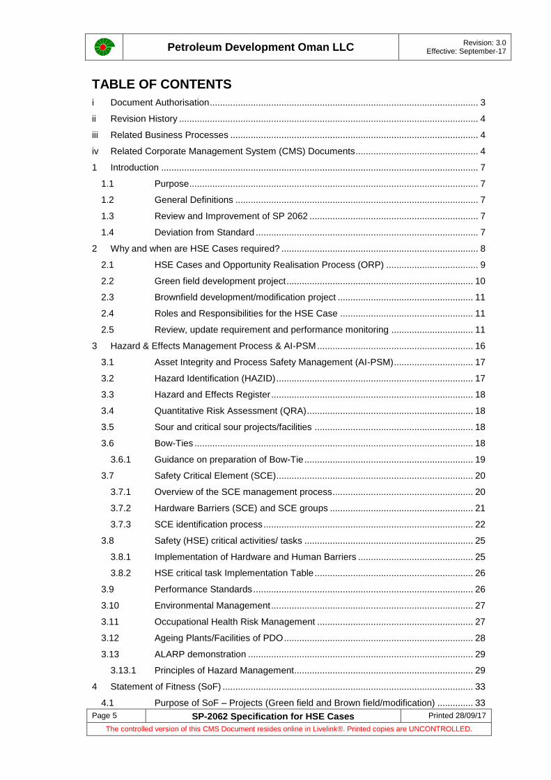
2.4 Roles and Responsibilities for the HSE Case
There are three main roles for developing, implementing and maintaining an HSE Case; the HSE Case Owner, HSE Case Custodian and the HSE Case Administrator. Roles and responsibilities for HSE Cases are presented in Table 2-3.
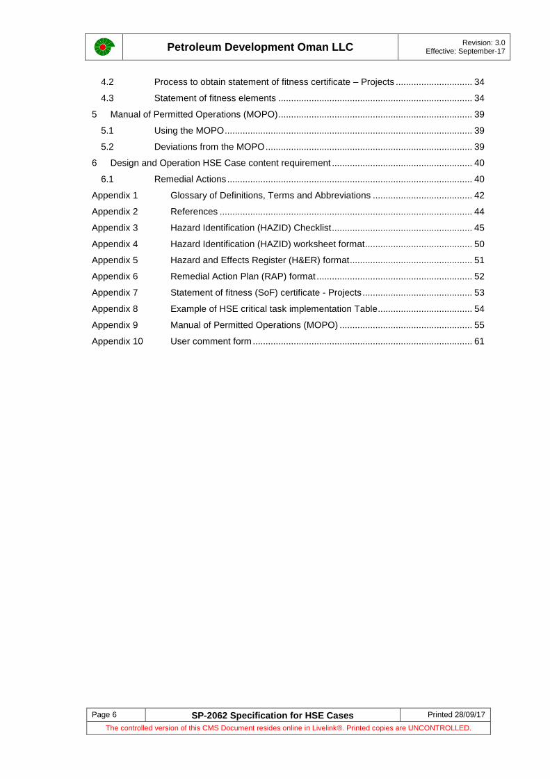
2.5 Review, update requirement and performance monitoring
Review, update requirement, performance monitoring for HSE case are presented in Table 2-4.

Petroleum Development Oman LLC
Revision: 3.0 Effective: September-17
Page 12 SP-2062 Specification for HSE Cases Printed 28/09/17
The controlled version of this CMS Document resides online in Livelink®. Printed copies are UNCONTROLLED.
Figure 2-2: HSE case decision tree for green field development project
Major Accident Hazard (MAH) –risk ranking of
3E,4D,4E,5A, 5B ,5C,5D,5E as per
PDO RAM?
Greenfield development project
Develop Design HSE case during Define (FEED) Phase and Update for changes during execute phase.
Generate operation HSE case during execute phase and signoff
before PSUA
Risk ranking of 4A,4B,4C,3A,3B,3
C, 3D, 2B, 2C,2D,2E as per
PDO RAM?
Project ALARP demonstration report in execute phase and sign-off before PSUA
5 yearly update of Operation HSE case. During such 5 yearly operation HSE case update, scope should also include projects that
are not covered in previous revision of operation HSE case.
Risk ranking of 1A,1B,1C,1D,1E,2A as per PDO RAM - manage hazards by continuous improvement and PDO HSE management system
Yes
No
Yes
No
Decision to generate new operation HSE case by operation leadership team
(Decision to be made before end of FEED)
Update relevant existing facility or cluster operation HSE case to include project facility scope and signoff before PSUA
Yes
No

Petroleum Development Oman LLC
Revision: 3.0 Effective: September-17
Page 13 SP-2062 Specification for HSE Cases Printed 28/09/17
The controlled version of this CMS Document resides online in Livelink®. Printed copies are UNCONTROLLED.
Figure 2-3: HSE case decision tree for Brownfield development/Modification project
Major Accident
Hazard (MAH) – risk ranking of
3E,4D,4E,5A, 5B
,5C,5D,5E as per PDO RAM?
Brownfield /modification project
Develop Design HSE case during Define (FEED) Phase and Update for changes during execute phase.
Is the identified MAH is new/additional to
existing MAH documented in the
facility or cluster operation HSE case?
Does the proposed
modification project brings significant
change to existing
facility risk profiles?
Update of relevant sections of existing operation HSE case (addendum)
during execute phase to manage impacts due to proposed project and signoff updated operation HSE case before PSUA.
Risk ranking of 4A,4B,4C,3A,3B,3C, 3D, 2B, 2C,2D,2E as
per PDO RAM?
Project ALARP demonstration report in execute phase and sign-off before PSUA. Note: Addendum/update of operation HSE case is not required. ALARP demonstration report is sufficient. Include project scope in 5 yearly operation HSE case update.
5 yearly update of Operation HSE case.
During such 5 yearly operation HSE case update, scope should also include projects that are not covered in previous revision of operation HSE case.
Risk ranking of 1A,1B,1C,1D,1E,2A as per
PDO RAM - manage hazards by continuous improvement and PDO HSE management system
Yes
No
Yes
Yes
No
No
Yes
No
Petroleum Development Oman LLC
Revision: 3.0 Effective: September-17
Page 14 SP-2062 Specification for HSE Cases Printed 28/09/17
The controlled version of this CMS Document resides online in Livelink®. Printed copies are UNCONTROLLED.
Table 2-3: Roles and Responsibilities for HSE Cases
Concept Select Report /Basis for Design report (CSR/BFD) Design HSE Case Operation HSE Case
HSE Case Owner Concept Engineer/ Project Manager
Ensure HSE Section in the CSR/BFD report.
Utilises services of asset TSE, Function TSE, MSE, MCOH staff to perform/QA of agreed deliverables.
Ensure multidiscipline review and approval of the Concept Select Report/BFD as per DCAF.
Capture “lesson learnt” in CSR/BFD by documenting lessons learnt from project relevant PDO AI-PSM incidents available in PDO incident database.
Ensure suitable design measures, safeguards are designed/ built for the proposed project and responsible for appropriate concept selection.
Responsible to close action items from all disciplines and to ensure project risks are managed to ALARP.
Project Manager
Identifies the requirement for Design HSE case in consultation with asset TSE/function during early Define/FEED stage.
Utilises project resources to develop Design HSE case during Define/ FEED.
Ensure update of design HSE case during Execute phase for changes and to include construction/commissioning hazards, assessment and to be communicated to construction/commissioning staff. Review design HSE case and to ensure multidiscipline review and approval of the Design HSE case as per DCAF/PCAP.
Responsible to close action items from all disciplines and to ensure project risks are managed to ALARP.
Ensure development of statement of fitness with the support of project team.
To keep orderly all relevant native files, HEMP models, HEMP study reports, Design HSE case reports & updates and to transfer all necessary documentation to operation HSE team leader.
For Greenfield development projects, responsible to initiate discussion with operation leadership team to make decision on whether to generate new operation HSE case or to update relevant existing facility or cluster operation HSE case to include project scope. This decision to be made before end of FEED for Greenfield development project. Multidiscipline review & approval of operation HSE case as per DCAF before PSUA.
Asset Director
Yearly discussion with respective operation leadership team to check the validity of existing operation HSE case and to ensure all PDO owned/leased operating facilities in the directorate are covered in Operation HSE Case.
Establish and review communication program to ensure content and intent of operation HSE case is communicated to relevant staff.
Ensure Letter of Assurance process is completed – Asset Annual Declaration
Review and final signature on operation HSE case document whenever updated or generated for green filed development projects.
HSE Case Custodian
N/A Project Lead Technical Safety Engineer (PDO)
Ensure HEMP studies are suitably carried out to identify and assess the Major Accident hazards and risks associated with project.
Ensure development of design HSE case as per the requirement of this document or any additional instruction from MSE4. Ensure update of design HSE case during Execute phase for changes and to include construction/commissioning hazards and assessment.
Responsible to ensure Identification of safety critical elements (SCE) and associated Performance Standards (design, procurement, fabrication, construction, commissioning, operation phase) together with other discipline Technical Authorities (TA).
Coordinate project manager during SCE SAP registration.
Co-ordinates with project manager to develop Statement of Fitness for the project.
Co-ordinate with project manager to close action items from all disciplines and ensure project risks are ALARP.
Responsible to plan and deliver operation HSE case report for green field development projects and to ensure multidiscipline review and approval of the operation HSE case as per DCAF before PSUA. Refer to flowchart on HSE case requirement for green field development project.
Delivery Team Leader
Ensure operation HSE case is maintained for their assets in accordance with latest requirements.
Responsible to allocate relevant operation/maintenance staff during the development/update of design and operation HSE case.
Ensure SCEs are operated, maintained and inspected as per operation Performance Standards.
Responsible to ensure appropriate level of competence for HSE critical roles by regular monitoring and training programmes.
Review operation HSE case content and sign-off as custodian
Responsible for Letter of Assurance – Asset Annual Declaration
Supports asset director/ operation leadership team to establish and review communication program to ensure content and intent of operation HSE case is communicated to relevant staff.
Ensure closure of relevant L1/L2 audit, HBA and incident investigation findings by coordinating with asset team.
Responsible for monitoring and closure of recommendations from Remedial Action Plan (RAP) of operation HSE case.
Ensure fit for purpose facility emergency response plans.
HSE Case Administrator
N/A
N/A
Note: Operation HSE case shall be generated for green field development projects during execute phase and multidiscipline review & approval of operation HSE case as per DCAF before PSUA is required. Refer to flowchart on HSE case requirement for green field development project. Project manager to keep orderly all relevant native files, HEMP models, HEMP study reports, Design/Operation HSE case reports and to transfer all necessary documentation, native files to operation HSE team leader.
Operation HSE team leader (OSS,ONS,GGS)
Initiates and drives Operations HSE Case update and assigns responsibilities.
Compiles/co-ordinates the operation HSE Case and subsequent reviews and updates.
Seeks necessary support from asset Technical Safety Engineer, function and other discipline during development and update of operation HSE case.
Participates in review of design HSE case/update during define and execute phase.
Participates in review of operation HSE case during execute phase for Greenfield development project.
Responsible to keep orderly all relevant native files, operation HSE case reports.
Responsible to obtain all relevant native files, HEMP study reports, Design/Operation HSE case reports and all necessary documentation from project manager for green field development project.
Supports asset director to establish and review communication Program to ensure content and intent of operation HSE case is communicated to relevant staff.
Assist Letter of Assurance – Asset Annual Declaration activities
Ensure multidiscipline review and assurance of operation HSE case as per DCAF.
Supports operation HSE Case Custodian and Owner in closing L1/L2 audit, HBA and incident investigation findings and helps closure of recommendations from Remedial Action Plan (RAP) of operation HSE case.
Support DTL/Operation team during review/update of facility emergency response plans.
Petroleum Development Oman LLC
Revision: 3.0 Effective: September-17
Page 15 SP-2062 Specification for HSE Cases Printed 28/09/17
The controlled version of this CMS Document resides online in Livelink®. Printed copies are UNCONTROLLED.
Table 2-4 Review, update requirement and performance monitoring for HSE cases
Project life cycle – HSE cases
HSE case review, update requirement and performance monitoring
Concept Select report/ Basis for Design Report - Select Phase
Multidiscipline review and approval of the CSR/BFD as per DCAF prior to VAR 3a/3b respectively.
Design HSE case - Define Phase/Execute Phase
The Design HSE Case need to go through several revisions during the Define and Execute phases depending on the nature of the project and changes.
Multidiscipline review and approval of the define phase Design HSE case as per DCAF/PCAP prior to VAR4/FID. Update of define phase Design HSE case during execute phase for changes. Refer Note 1. If define phase design HSE case has not covered construction/commissioning hazards, these hazards and assessment shall be included during the update of design HSE case during execute Phase and prior to construction and commissioning activities and to be communicated to relevant construction/commissioning staff. Multidiscipline review and approval of the execute phase design HSE case update as per DCAF/PCAP. Generate operation HSE case for green field development project and multidiscipline review and approval prior to PSUA.
Operate Phase HSE case
The Operations HSE Case shall be reviewed and updated at a maximum interval of 5 years. During such 5 year operation HSE case update, include projects which were not covered in previous revision of operation HSE case.
Immediate update (Not to wait for 5 yearly update) of operation HSE case is required during following circumstances:
Due to significant change to the facility, operation envelope or surrounding environment that impacts the existing risk profile adversely.
Decision by PDO to accept new international standards/regulation/Omani legislation that can impact assumption, conclusion on risk tolerability in existing operation HSE case.
Significant change during operation phase is any change that affects the basis or impacts the existing risk profile documented in operation HSE case adversely. MSE4 team should be consulted for further guidance/discussion on significant changes during operation phase Examples for significant change during operation phase include but not limited to the following:
Increase in hydrocarbon and toxic inventory streams, composition changes, increased manning levels, increased operational complexity, compromised layout, Introduction of sour/critical sour streams to existing sweet facilities.
Modifications or repairs to the plant/facilities, either as single large modification or multiple smaller modifications resulting in increased risk profile/SIMOPs risk.
Transfer of assets from one cluster to another or from one directorate to another. In case of identification of significant change during operation phase, Operation HSE team leader shall initiate operation HSE case update and need not wait for maximum interval of 5 years.
Update of operation HSE case is not required in case of changes to operation HSE case Owner/custodian/administrator. HSE case Owner/custodian/administrator should familiarize with existing up to date operation HSE case whenever such changes occur.
Multidiscipline review and approval of the Operation HSE case as per DCAF/ACAL and sign-off by Operation HSE case administrator, custodian and owner.
Note1: Changes during design phase is any change that affects the basis or risk profiles documented in define phase design HSE Case. Examples for design change include but not limited to the following:
Changes in process parameter, fluid composition, increased hydrocarbon and toxic inventory, change in type of equipment, layout changes, increased congestion/confinement, changes to design& safeguarding basis, introduction of additional risks (SIMOPs), changes in manning level/ occupancy.
Change during design phase may also arise due to decision by PDO to accept new international standards/regulation & Omani legislation that can impact assumption, conclusion on risk tolerability/acceptability. MSE4 should be consulted for further guidance /discussion on changes during design phase.

Petroleum Development Oman LLC
Revision: 3.0 Effective: September-17
Page 16 SP-2062 Specification for HSE Cases Printed 28/09/17
The controlled version of this CMS Document resides online in Livelink®. Printed copies are UNCONTROLLED.
3 Hazard & Effects Management Process & AI-PSM
PDO incident database based on analysis of AI-PSM tier-1 incidents between 2007 and 2016 indicates that roughly 56% of the Tier-1 incidents are due to “Design issues/faults”. 56% of the Tier-1 incidents between 2007 and 2016 equates to 72 Tier-1 incidents.[Ref: 2]. Effective design and specifications are important to avoid Tier-1/2 incidents.
The objective of Hazard and Effects Management Process (HEMP) is to identify HSE hazards, to asses HSE hazards and to implement control and recovery measures. Integral part of HEMP is to have documents to demonstrate that major HSE risks have been reduced to a level that is considered As Low As Reasonably Practicable (ALARP).
HEMP shall be applied to cover the entire lifecycle of the asset; from concept through to decommissioning and disposal.
The HEMP process comprises four basic steps:
Systematic identification of hazards, threats/causes and their effects
Assessment of the risks against screening criteria, taking into account the likelihood of unwanted events and the potential severity of the consequences in terms of effects to people, assets, the environment and reputation of PDO
Implementation of suitable risk reduction measures to control or mitigate the hazard and its effects
Planning for recovery in the event of a loss of control
Effective documentation of HEMP studies and continual improvement of HEMP by incorporating lessons learnt in to PDO projects/operations and/or by improving the steps involved in HEMP model is an integral part of HEMP.
Asset Integrity – Process Safety Management (AI-PSM) describes the way in which PDO assets are managed so that the process safety risk is ALARP and Design Integrity, Technical Integrity and Operation Integrity are assured and intact.
The HEMP model and AI-PSM in PDO is presented in Figure 3-1.
Figure 3-1: HEMP Model and AI-PSM in PDO
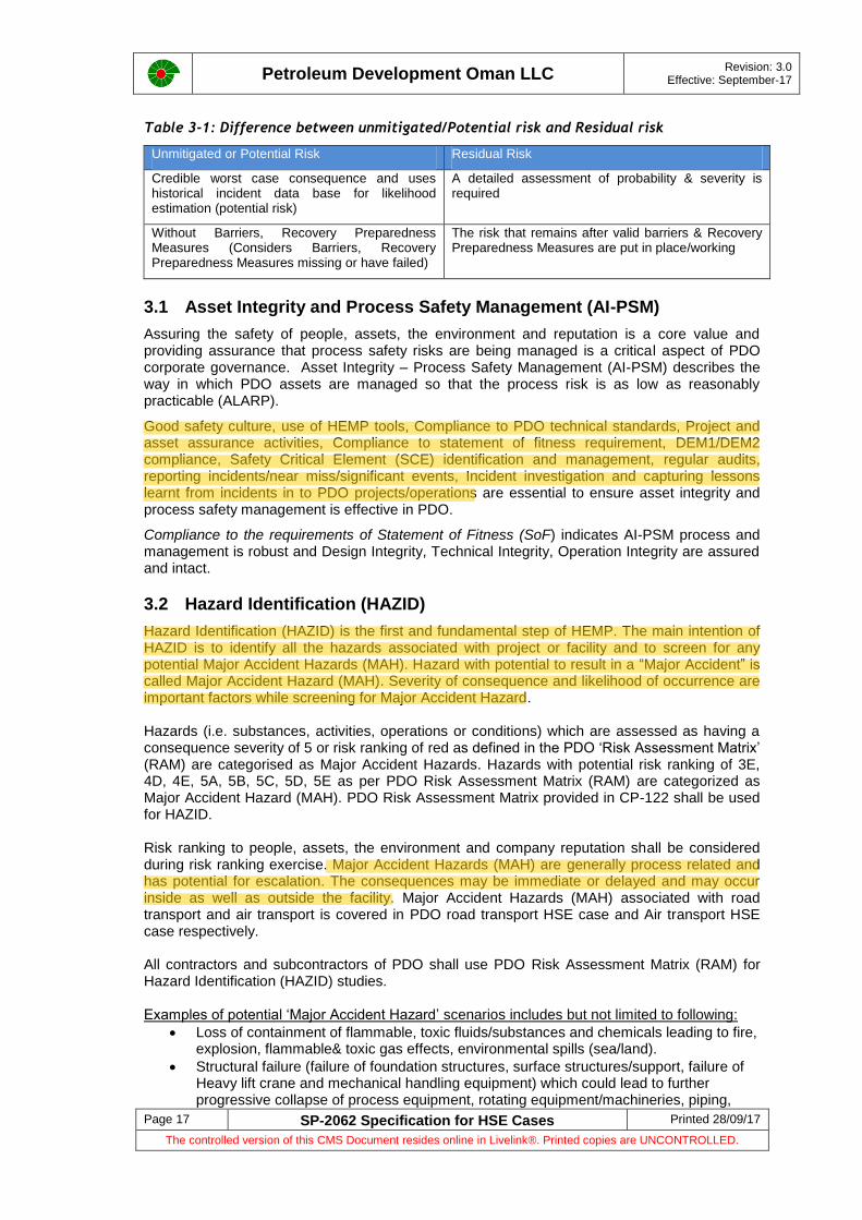
HEMP studies shall be performed by staff who are knowledgeable about the facility and operations and who are competent in the HEMP tools/techniques. The HEMP studies to be planned and implemented in a timely manner to enable the results to be incorporated without incurring avoidable rework and costs. Recommendations arising from HEMP studies shall be recorded in an appropriate action tracking system. The basic difference between unmitigated/potential risk and residual risk is provided in the Table 3-1.
Assess
ControlRecover
Identify Integrity
DesignTechnical
Integrity
Technical
Integrity
Operating
Integrity
People
&
Systems
We construct and maintain the
hardware barriers
We design so that risks are As
Low As Reasonably Practicable
We operate our facilities within
defined limits and with up to
date procedures and effective
communications
We have competent people,
with the right behaviours
working with fit for purpose
systems
Petroleum Development Oman LLC
Revision: 3.0 Effective: September-17
Page 17 SP-2062 Specification for HSE Cases Printed 28/09/17
The controlled version of this CMS Document resides online in Livelink®. Printed copies are UNCONTROLLED.
Table 3-1: Difference between unmitigated/Potential risk and Residual risk
Unmitigated or Potential Risk Residual Risk
Credible worst case consequence and uses historical incident data base for likelihood estimation (potential risk)
A detailed assessment of probability & severity is required
Without Barriers, Recovery Preparedness Measures (Considers Barriers, Recovery Preparedness Measures missing or have failed)
The risk that remains after valid barriers & Recovery Preparedness Measures are put in place/working
3.1 Asset Integrity and Process Safety Management (AI-PSM)
Assuring the safety of people, assets, the environment and reputation is a core value and providing assurance that process safety risks are being managed is a critical aspect of PDO corporate governance. Asset Integrity – Process Safety Management (AI-PSM) describes the way in which PDO assets are managed so that the process risk is as low as reasonably practicable (ALARP).
Good safety culture, use of HEMP tools, Compliance to PDO technical standards, Project and asset assurance activities, Compliance to statement of fitness requirement, DEM1/DEM2 compliance, Safety Critical Element (SCE) identification and management, regular audits, reporting incidents/near miss/significant events, Incident investigation and capturing lessons learnt from incidents in to PDO projects/operations are essential to ensure asset integrity and process safety management is effective in PDO.
Compliance to the requirements of Statement of Fitness (SoF) indicates AI-PSM process and management is robust and Design Integrity, Technical Integrity, Operation Integrity are assured and intact.
3.2 Hazard Identification (HAZID)
Hazard Identification (HAZID) is the first and fundamental step of HEMP. The main intention of HAZID is to identify all the hazards associated with project or facility and to screen for any potential Major Accident Hazards (MAH). Hazard with potential to result in a “Major Accident” is called Major Accident Hazard (MAH). Severity of consequence and likelihood of occurrence are important factors while screening for Major Accident Hazard. Hazards (i.e. substances, activities, operations or conditions) which are assessed as having a consequence severity of 5 or risk ranking of red as defined in the PDO ‘Risk Assessment Matrix’ (RAM) are categorised as Major Accident Hazards. Hazards with potential risk ranking of 3E, 4D, 4E, 5A, 5B, 5C, 5D, 5E as per PDO Risk Assessment Matrix (RAM) are categorized as Major Accident Hazard (MAH). PDO Risk Assessment Matrix provided in CP-122 shall be used for HAZID. Risk ranking to people, assets, the environment and company reputation shall be considered during risk ranking exercise. Major Accident Hazards (MAH) are generally process related and has potential for escalation. The consequences may be immediate or delayed and may occur inside as well as outside the facility. Major Accident Hazards (MAH) associated with road transport and air transport is covered in PDO road transport HSE case and Air transport HSE case respectively. All contractors and subcontractors of PDO shall use PDO Risk Assessment Matrix (RAM) for Hazard Identification (HAZID) studies. Examples of potential ‘Major Accident Hazard’ scenarios includes but not limited to following:
Loss of containment of flammable, toxic fluids/substances and chemicals leading to fire, explosion, flammable& toxic gas effects, environmental spills (sea/land).
Structural failure (failure of foundation structures, surface structures/support, failure of Heavy lift crane and mechanical handling equipment) which could lead to further progressive collapse of process equipment, rotating equipment/machineries, piping,

Petroleum Development Oman LLC
Revision: 3.0 Effective: September-17
Page 18 SP-2062 Specification for HSE Cases Printed 28/09/17
The controlled version of this CMS Document resides online in Livelink®. Printed copies are UNCONTROLLED.
tanks, flow lines / trunk lines/ pipelines resulting in fire, explosion, flammable& toxic gas effects, environmental spills (sea/land).
Well blowout resulting in fire, explosion, flammable& toxic gas effects, environmental spills (sea/land).
Loss of containment of steam system, Boiler explosion, Transformer fire/explosion.
Flare flameout (Depending on fluid composition, proximity to people etc).
Uncontrolled runaway polymerization reaction
Catastrophic failure of liquefied nitrogen storage tank
Accident related to road/marine transport of flammable, explosive and toxic substances, Includes but not limited to - Chemicals, Intermediates, Well fluids (Gross), Crude oil, HC Condensate, HC gas/liquids, NGL, LNG, LPG, DME.
Ships colliding with offshore installations or onshore jetties used for bulk loading of flammable, explosive or toxic substances resulting in fire, explosion, flammable& toxic gas effects, environmental spills.
Warehouse Fire, explosion (Fire, explosion at Universal Freight warehouse, Yorkshire. 13th February 1982, BASF, Wilton, Teeside. 9th October 1995, Warehouse fire, explosion, China)
Detail HAZID checklist and HAZID worksheet format available in Appendix 3 and 4 respectively helps to effectively capture information associated with hazards and to analyse and subsequent management of hazards. HAZID checklist of Rev1 SP-2062 was improved/rationalised using ISO17776 checklist [Ref: 3, 4].
3.3 Hazard and Effects Register
Green field development projects which qualify to generate Design HSE case and Operation HSE case are required to generate Hazard and Effect Register (H&ER) as an integral part of HSE case. For Greenfield development projects, if the decision by project and operation team is to update relevant existing facility or cluster operation HSE case to include project scope, then existing facility or cluster H&ER is updated to include the project scope.
All other projects (example: Off-plot Delivery Contract , Combined FEED/DD) need not generate Hazard and Effect Register (HAZID is sufficient) and upon commissioning such project scope to be included in 5 yearly update of operation HSE case and facility or asset Hazard and Effect Register shall be updated.
Every PDO facility/cluster is expected to have updated Hazard and effect register. As part of 5 yearly or immediate update of operation HSE case, H&ER for facility/cluster shall be updated.
H&ER covers Major Accident Hazards (MAH) and other hazards which are not rated as MAH.Hazard and Effects Register format is provided in Appendix 5.
3.4 Quantitative Risk Assessment (QRA)
QRA requirements for projects/facilities are specified in SP-1258 and available in Corporate Management System (CMS).
3.5 Sour and critical sour projects/facilities
Design and operation requirements for sour and critical sour projects/facilities are specified in SP-1190 and available in Corporate Management System (CMS).
3.6 Bow-Ties
Process hazards that have been assessed as being a severity 5 or risk ranking of red on the PDO Risk Assessment Matrix (RAM) are modelled further using Bow-tie methodology.
The Bow-Tie analysis identifies threats, consequences and escalation factors associated with a specific hazard and determine the necessary barriers, recovery preparedness measures and escalation factor controls to manage the risk. ‘Bow-Tie XP’ is the PDO preferred software tool.

Petroleum Development Oman LLC
Revision: 3.0 Effective: September-17
Page 19 SP-2062 Specification for HSE Cases Printed 28/09/17
The controlled version of this CMS Document resides online in Livelink®. Printed copies are UNCONTROLLED.
Typical Bow-Tie model is presented Figure 3-2. SP-2062 provides guidance on acceptance criteria for Barriers, Recovery Preparedness Measures (RPM), and Escalation Factor Controls (EFC) for Major Accident Hazards (MAH). Setting acceptance criteria helps project to analyze equipment safeguarding and during ALARP demonstration.
Figure 3-2: Typical bow-tie model
Bow-ties should to be generated and validated as per new Shell Global Bow-tie guidance [Ref: 5]. Expectation is to generate equipment specific bow-ties during Define (and update during execute phase) as per the guidance provided below
Guidance on Acceptance criteria for Barriers, Recovery Preparedness Measures (RPM), and Escalation Factor Controls (EFC) for Major Accident Hazards (MAH) is presented in Table 3-2.
Table 3-2: Acceptance criteria for Barriers, RPM and EFC
3.6.1 Guidance on preparation of Bow-Tie
Step wise guidance for preparation of Bow-Tie is presented in Table3-3.
Table 3-3: Guidance on preparation of Bow-Tie
Steps Description
Step 1 Preliminary Bow-Ties: Preliminary Bow-Ties should be developed by facilitator as a desktop study
to a detailed, tag level using project HAZID, HAZOP Report, Process Design Basis and Process Engineering Flow Scheme - PEFS. The objective of this desktop study is to create Bow-Ties with specific detail on threats, barriers, consequence and recovery preparedness measures and ensure
Risk as per PDO risk assessment matrix Item Acceptance criteria
Major Accident Hazard (MAH) area (Hazards with potential risk ranking of 3E, 4D, 4E, 5A, 5B, 5C, 5D, 5E as per PDO risk assessment matrix are categorized as Major Accident Hazard - MAH)
Barriers (Preventive) Minimum of 3 independent, effective and auditable barriers for each identified threat/cause line
Recovery Preparedness Measures (RPM)
Minimum of 2 independent, effective and auditable Recovery Preparedness Measures (RPM) for each identified consequence
Escalation Factor Controls (EFC)
Minimum of 2 Escalation Factor Controls (EFC) for each identified Escalation Factor
Petroleum Development Oman LLC
Revision: 3.0 Effective: September-17
Page 20 SP-2062 Specification for HSE Cases Printed 28/09/17
The controlled version of this CMS Document resides online in Livelink®. Printed copies are UNCONTROLLED.
Steps Description
availability of basic bow-tie structure for post HAZOP bow-tie workshop. This will improve efficiency and saves time during step 2.
Step 2 Post HAZOP bow-tie workshop: Bow-tie validity exercise should be carried out to ensure barriers and recovery preparedness measures are independent, effective and auditable in line with shell global bow-tie guidance in a workshop environment attended by project team, operation& maintenance representative. Relevant escalation factor and escalation factor controls should be identified for barriers and recovery preparedness measures in line with shell global bow-tie guidance. Guidance on acceptance criteria for Barriers, RPM and EFC for Major Accident Hazards (MAH) provided in SP-2062 should be applied.
Post-HAZOP Bow-Ties should be further updated using the information gathered from the IPF report, i.e. to update the SIL ratings of any IPF used as a barrier or recovery preparedness measures in the Bow-Ties. This update exercise can be desktop exercise from Bow-tie facilitator.
Step 3 Final Bow-Tie review: Final Bow-Tie review by project team, operation& maintenance
representative and Bow-tie facilitator is required once IPF report information is incorporated in to Bow-tie. Final Bow-tie review should confirm sufficient project and equipment specific details on Threats, Barriers, Escalation Factors and Escalation Factor Controls. Efficient work in step 1 and step 2 reduces the number of hours required for review in step3 significantly.
Information: Deficiency in meeting the acceptance criteria for barriers, recovery measures and escalation factor controls should be captured and discussed with project TSE and TSE TA-2 and the way forward to be sought.
3.7 Safety Critical Element (SCE)
A Safety Critical Element (SCE) is any item of hardware, structure, system or logic software the failure of which could cause a Major Accident Hazard (MAH) or whose purpose is to prevent or control, mitigate the effects of a MAH. Safety Critical Element (SCE) has the same meaning of HSE Critical Element.
3.7.1 Overview of the SCE management process
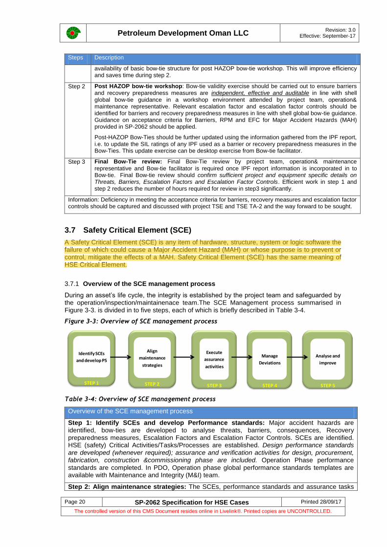
During an asset’s life cycle, the integrity is established by the project team and safeguarded by the operation/inspection/maintainenace team.The SCE Management process summarised in Figure 3-3. is divided in to five steps, each of which is briefly described in Table 3-4.
Figure 3-3: Overview of SCE management process
Table 3-4: Overview of SCE management process
Overview of the SCE management process
Step 1: Identify SCEs and develop Performance standards: Major accident hazards are identified, bow-ties are developed to analyse threats, barriers, consequences, Recovery preparedness measures, Escalation Factors and Escalation Factor Controls. SCEs are identified. HSE (safety) Critical Activities/Tasks/Processes are established. Design performance standards are developed (whenever required); assurance and verification activities for design, procurement, fabrication, construction &commissioning phase are included. Operation Phase performance standards are completed. In PDO, Operation phase global performance standards templates are available with Maintenance and Integrity (M&I) team.
Step 2: Align maintenance strategies: The SCEs, performance standards and assurance tasks
Identify SCEs
and develop PS
STEP 1
Align
maintenance
strategies
STEP 2
Execute
assurance
activities
STEP 3
Manage
Deviations
STEP 4
Analyse and
improve
STEP 5

Petroleum Development Oman LLC
Revision: 3.0 Effective: September-17
Page 21 SP-2062 Specification for HSE Cases Printed 28/09/17
The controlled version of this CMS Document resides online in Livelink®. Printed copies are UNCONTROLLED.
Overview of the SCE management process
are brought together to determine the tasks, their frequencies and to embed them into the planned maintenance routines within the Computerised Maintenance Management System (CMMS).
Step 3: Execute performance assurance tasks: The SCEs performance assurance tasks are carried out to check whether the SCEs are functioning correctly and to identify corrective actions (where required). The outcomes are completed performance assurance tasks, recorded results, follow-on work initiated for failed performance checks and performance assurance tasks that have not been completed on time
Step 4: Manage deviations: The risk associated with a backlog of assurance and safety critical work orders are properly assessed, authorised and appropriate mitigating actions taken to control the risks.
Step 5: Analyse and improve: The status of the hardware barriers and performance assurance tasks are made readily available to operating staff to enable management of the ongoing conformance of SCEs with their performance standards. This stage provides the visible demonstration that the SCEs are functioning correctly or that non-conformances are managed through deviations. Helps to improve steps 1, 2, 3, 4 & 5 as part of continuous improvement.
Facility Status Reporting (FSR) Facility Status Reporting is the global standard tool to support the management of SCEs and it has three main functions.
Visualisation (consolidated picture) of the status of the CMMS work orders, notifications and related deviations by barrier/SCE group at any level with in the FSR asset hierarchy.
Communication – FSR monitors those items that require actions, and notifies the relevant parties.
A formal and auditable deviation management system.
3.7.2 Hardware Barriers (SCE) and SCE groups
Hardware barriers for Major Accident Hazard (MAH) are high level groupings of SCEs used for reporting and management purposes. There are eight hardware barriers as shown in Figure 3-4, which represent the two sides of the Bow-tie. Only those barriers identified from bow-tie model are relevant for an asset/facility. Table 3-5 lists the hardware barriers.
Table 3-5: Hardware barriers
Hardware barriers Code
Structural Integrity SI
Process Containment PC
Ignition Control IC
Detection Systems DS
Protection Systems PS
Shutdown Systems SD
Emergency Response ER
Life Saving Equipment LS
Each hardware barrier is sub-divided in to SCE groups for reporting and management purposes. SCE groups are only relevant to an asset if corresponding Safety Critical Elements are identified from Bow-Tie model. The SCE groups are listed against their respective barrier in Figure 3-4. The SCE management manual SR.14.11269 [Ref: 6] describes the activities and processes for managing the Safety Critical Elements (SCEs).
Figure 3-4: Hardware barriers and SCE groups

Petroleum Development Oman LLC
Revision: 3.0 Effective: September-17
Page 22 SP-2062 Specification for HSE Cases Printed 28/09/17
The controlled version of this CMS Document resides online in Livelink®. Printed copies are UNCONTROLLED.
3.7.3 SCE identification process
Flowchart for SCE identification process is presented in Figure 3-5 and applicable for all PDO projects. Identification of Major Accident Hazard (MAH) as part of Hazard Identification exercise is the first step. Bow-ties are developed as per the guidance provided in section 3.6.1 – Guidance on preparation of Bow-Tie. Hardware barriers (SCEs) shall be identified from fully developed Bow-Tie. Only those barriers identified from bow-tie model are relevant for an asset/facility. Safety (HSE) Critical Activities, tasks and processes are established for identified Barriers, Recovery Preparedness Measures and Escalation Factor Controls in line with section 3.8 of SP-2062. During development of the Bow-Tie diagrams, Inherent safety barriers, Safety Critical Elements, HSE Critical Activities & processes and Actions raised should be colour coded as per Table 3-6.

Petroleum Development Oman LLC
Revision: 3.0 Effective: September-17
Page 23 SP-2062 Specification for HSE Cases Printed 28/09/17
The controlled version of this CMS Document resides online in Livelink®. Printed copies are UNCONTROLLED.
Whenever, project team fails to identify Major Accident Hazards (MAH) and SCE, additional checks as shown in Figure 3-5 are essential to confirm, project team has not missed an opportunity to identify SCE associated with project.
Asset/ Project Technical Safety Engineer are responsible for identification of SCEs. Asset or project TSE should to follow-up with project engineer, Maintenance & Integrity team during SCE SAP registration to ensure appropriate Functional location criticality classification.
The SCE Identification document should provide clear rationale for SCE identification (reason for SCE award) by linking it to identified MAH, good quality Bow-tie. Functional location criticality classification of either A, B or C is required to establish suitable maintenance, inspection and deviation management strategy.
Design performance standards (Whenever required) should identify and list assurance and verification activities for design, procurement, fabrication, construction &commissioning phase.
Operation phase performance standards help organisation to align maintenance and inspection strategies, execute assurance activities and to manage deviations. In PDO, Operation phase global performance standards templates are available with Maintenance &Integrity (M&I) team. When required, project team should contact M&I team for latest revision of operation phase global performance standard template.
Table 3-6: Bow-Tie development – Colour coding
Item Description
Inherent Safety
Inherent facility/process design feature. Example includes but not limited to: Elimination of hazards, Substitution – use of processes or methods with lower risk potential, adequate separation distance.
Safety Critical Element
Hardware barriers (SCE) can be preventive barrier or control & Recovery Preparedness Measures for which performance standards have/will be developed. There are 8 hardware barriers and each hardware barrier is sub-divided in to SCE groups for reporting and management purposes.
Example includes but not limited to : Pressure vessels, Heat exchangers, Rotating equipment, tank, piping systems, pipelines, relief system, certified electrical equipment, fire and gas detection, deluge systems, fire water pumps, passive fire protection, Emergency shutdown system, depressurisation system, high integrity pressure protection system, Process emergency shutdown valves, pipeline isolation valves, Escape and evacuation routes, personal survival equipment, emergency power, drain system.
HSE Critical Activity &Processes
Includes human barriers/intervention, established procedures and critical processes.
Example includes but not limited to: Operating in accordance with procedures, response to process alarm and upset conditions, lockout/tag out, Management of Change, PTW system, Emergency Response, Competency management, Contractor management, DCAF, Wells integrity management, HSE management system, Facility Status Report (FSR), Corrosion management, surveillance, operator rounds and routine inspections, Authorization of temporary and mobile equipment.
Inspection and maintenance are typically not barriers but serve as tasks to maintain the integrity of barriers. They are incorporated in the Bow-Tie as Safety Critical Activities (SCA) or HSE critical activity.
Action
Action items and items requiring further clarification.

Petroleum Development Oman LLC
Revision: 3.0 Effective: September-17
Page 24 SP-2062 Specification for HSE Cases Printed 28/09/17
The controlled version of this CMS Document resides online in Livelink®. Printed copies are UNCONTROLLED.
Figure 3-5: Flow chart for SCE identification process
Information 1: In case of MAH identification for projects (ODC, EMC, Combined FEED/DD), respective cluster or facility operation HSE case Bow-tie can be directly utilised (if ready to use) to identify SCE or Bow-tie can be updated or prepared to identify SCE.
Information 2: To all projects below US$50 million (i.e. total Capex excl. infill drilling) with a risk rating of Low or medium as defined in CP-223; A project-specific TIV Plan shall not be produced, Project-specific design performance standards shall not be produced, Independent verification body shall not be engaged, A project-specific TIV Report shall not be Produced.Information 2 is based on FRD-2 communication and minimum assurance tasks which needs to be done for such projects are mentioned in FRD-2 communication.
No
Yes
Yes
Yes to any one of the question?
No to all
questions?
Yes
No
Yes
Business critical [B]
or Non-critical [C]
No
Yes
NoMAH identified?
Hardware Barriers
from Bow-tie model identified?
Q1. Could the failure of this
element cause Major Accident Hazard (MAH)?Q2. Is the purpose of this element
is to prevent the top event of an MAH?Q3. Is the purpose of this element is to limit/mitigate the consequences of an MAH?Q4. Is the purpose of this element is to support during escape,
evacuation, emergency response?
Construct Bow-Tie as per Shell global bow-tie
guidance and criteria set in SP-2062. (See information 01)
Safety Critical Elements (SCE) – [A]
identification
Develop design phase performance standards. Identify verification and
assurance activities for Design, Procurement, Fabrication, Construction and Commissioning phase and perform phase wise TIV activities as per TIV plan. (See Information 02)
Complete global operation phase performance standards available with M&I team& Complete SAP registration with rationale for Safety Critical Elements [A], Business Critical [B], Non-critical [C]. To be completed before PSUA
Does the project equipment or
element belongs to any of the SCE
groups shown in existing cluster or
facility operation HSE Case?
Does the project
equipment or element belongs to any of the SCE
groups shown in PR-1992/SR.14.11269?
New element,
equipment?
Business critical [B] or Non-critical [C]
HAZID
No

Petroleum Development Oman LLC
Revision: 3.0 Effective: September-17
Page 25 SP-2062 Specification for HSE Cases Printed 28/09/17
The controlled version of this CMS Document resides online in Livelink®. Printed copies are UNCONTROLLED.
3.8 Safety (HSE) critical activities/ tasks
PDO incident database based on analysis of AI-PSM tier-1 incidents between 2007 and 2016 indicates that roughly 18% of the Tier-1 incidents are due to “Operator/Manintenance errors”. 18% of the Tier-1 incidents between 2007 and 2016 equates to 23 Tier-1 incidents. [Ref: 2]. PDO continuosly strives to eliminate operator/maintenance error by identifying safety (HSE) critical actvities/ tasks, up to date clear procedures and Safety(HSE) Critical processes.
A group or set of safety critical tasks necessary for the development, implementation, operation and or maintenance of a barrier or recovery preparedness measures or escalation factor control established for managing hazards with red risk on PDO RAM or Yellow 5A/5B risks (Major Accident Hazards) are defined as Safety critical activities/ HSE critical activities.
Personnel positions having the responsibility to design, implement, operate/maintain a barrier or recovery preparedness measures or escalation factor control established for managing hazards with red risk on PDO RAM or Yellow 5A/5B risks (Major Accident Hazards) are defined as Safety Critical (HSE critical) positions. In simple words, safety critical /HSE critical position personnel are those who execute or perform HSE critical activities/tasks.
A management process established to design, implement, operate/maintain a barrier or recovery preparedness measures or escalation factor control for managing hazards with red risk on PDO RAM or Yellow 5A/5B risks (Major Accident Hazards) are defined as Safety Critical (HSE critical) processes. Examples include but not limited to; Management of Change, PTW system, Emergency Response, Competency management, Contractor management, DCAF, Wells integrity management, Incident investigations, HSE management system, Facility Status Report (FSR), Corrosion management.
Safety Critical (HSE critical) processes are essential for the health of all hardware and human barriers as they support the effective design, construction, operation/execution, maintenance, testing and or inspection of barrier.
3.8.1 Implementation of Hardware and Human Barriers
A barrier may be hardware or human interventions (also called human barriers) or a combination of both. Hardware barriers are equipment, hardware or safety systems also called as a “Safety Critical Element”. These barriers are act to prevent top events or mitigate the consequences of a top event.
Human barriers rely on a human being as part of the barrier by initiating or taking actions in response to information to prevent the top event or mitigate the consequences. Human barriers in practice are often used in combination with hardware to perform an action (e.g., an operator response to alarm, initiating emergency response)
Hardware barriers must be developed, implemented and maintained to make sure that the barrier functions properly. Human barriers need human interventions (actions/tasks) to function and prevent the top event or mitigate the consequences. The identification of the safety critical elements and safety critical activities support the implementation of valid hardware and human barriers.
Safety Critical Activities (SCA) may be linked to procedures or processes which are identified to ensure that the Safety Critical Activities (SCA) are carried out when and as required. Each activity/task should be assigned to a responsible HSE critical position. Personnel in these positions should be competent in executing the activity/task allocated to them. SCAs should have defined inputs and outputs i.e. (Performance standards and inspection records)
Inspection and maintenance are typically not barriers but serve as HSE (safety) critical activity/tasks to maintain the integrity of barriers. They are incorporated in the Bow-Tie as SCAs.
Bow-tie XP software enables the HSE critical tasks to be linked to the relevant barriers.
Implementation of hardware and human barriers and relationship with HSE critical activity/Safety Critical Activities, Safety Critical (HSE critical) positions Safety Critical (HSE critical) processes is explained in Figure 3-6.

Petroleum Development Oman LLC
Revision: 3.0 Effective: September-17
Page 26 SP-2062 Specification for HSE Cases Printed 28/09/17
The controlled version of this CMS Document resides online in Livelink®. Printed copies are UNCONTROLLED.
Figure 3-6: Implementation of Hardware and Human Barriers
3.8.2 HSE critical task Implementation Table
The minimum information required for a HSE critical task shall be:
The description and purpose of the HSE critical task required
The person (position and reference indicator) responsible for performing each task
Reference to supporting documentation, e.g. work instructions, SAP, procedure
The method and criteria to verify that the task is performed as required to maintain barrier effectiveness.
HSE critical task implementation tables should be developed for each HSE Critical Position. Letter of Appointment will be signed by the individual undertaking the safety critical roles. Refer to PR-2234 for more information.
See Appendix 8 for an example and format for HSE critical task implementation table.
3.9 Performance Standards
A Performance Standard (PS) describes the performance criteria for a SCE and used as the basis for design, technical and operational integrity verification. Performance standards are expressed in terms of functionality, availability, reliability, survivability and dependencies/ interactions with other SCEs. SCEs and Performance Standards follow a one-to-one relationship where each SCE has its own Performance Standard.
Functionality
Functionality is an expression used to define what the system or equipment is required to achieve in order to ensure design integrity.
Identify
Hardware
barriers (SCEs )
associated
with MAH
Establish Hardware Barrier
Identify Human
barriers
associated with
MAH
Establish Human Barrier
Identify Safety Critical
Activities (SCA) or HSE
critical activities
What activities/tasks are required to develop, implement, operate and
maintain hardware & human barrier (Refer to SCA definition for clarity)
Assign to HSE critical
positions
Who is responsible for performing/executing
SCA
Assign to HSE critical
procedures/processes
When and how to carryout SCA

Petroleum Development Oman LLC
Revision: 3.0 Effective: September-17
Page 27 SP-2062 Specification for HSE Cases Printed 28/09/17
The controlled version of this CMS Document resides online in Livelink®. Printed copies are UNCONTROLLED.
Reliability and Availability
Reliability is defined as the required probability that the system or equipment will operate on demand, when required.
Availability is defined as the extent to which the system or equipment is required in order to retain its functional integrity.
Survivability
Survivability defines the external loading events such as fires, explosions or extreme weather, associated with the various MAHs against which the system or equipment is required to retain its functional integrity.
Dependencies and Interactions
This is used to identify other systems or equipment which are critical to the functionality of the primary system or equipment. By identifying these dependencies and interactions it is ensured that all interfaces have been covered.
There are two types of Performance standards;
Design Performance Standards. Design Performance Standards (Whenever required) must be developed during the Define phase. They shall provide a list of key functional criteria to which the SCE must comply with during the design. Design performance standards should also identify and list assurance and verification activities for design, procurement, fabrication, construction &commissioning phase. In practice the content of the performance standards will be largely taken from the design and engineering standards that apply to the item or SCE. However, information may be also taken from the basis for design, the design philosophies, HEMP Studies such as HAZID/HAZOP, Design Review, Layout Reviews, Fire & Explosion Analysis, QRA, IPF, SAFOP, etc.
The Design Performance Standards will mature further during the execute phase and will check that the SCEs have been procured, fabricated and constructed as designed. The existing QA/QC procedures and practices should be used to support the Design Performance Standards. The design must take into account operational demands so that suitability can be ensured into the operate phase.
Design performance standards document should be issued to Project Manager for approval along with relevant discipline TA-2 to provide comments/agreement as reviewer (IFR) during define and execute phase.
Operations Performance Standards.
Operation Performance Standard is a statement, which can be expressed in qualitative or quantitative terms of the functional performance required of a SCE and which is used as the basis for managing the risk from the Major Accident Hazards (MAH). Defining and ensuring compliance with suitable Performance Standards provides assurance that the SCE is and will remain a barrier to the identified MAH.
Operation phase performance standards helps organisation to align maintenance and inspection strategies, execute assurance activities and to manage deviations. In PDO, Operation phase global performance standards templates are available with Maintenance &Integrity (M&I) team. When required, project team should contact M&I team for latest revision of operation phase global performance standard template.
3.10 Environmental Management
Environmental management requirement for project & facilities should be dealt as per SP-2194.
3.11 Occupational Health Risk Management
Occupational health risks associated with the activities of PDO and its contractors should be dealt as per SP-1231.

Petroleum Development Oman LLC
Revision: 3.0 Effective: September-17
Page 28 SP-2062 Specification for HSE Cases Printed 28/09/17
The controlled version of this CMS Document resides online in Livelink®. Printed copies are UNCONTROLLED.
3.12 Ageing Plants/Facilities of PDO
PDO incident database based on analysis of AI-PSM tier-1 incidents between 2007 and 2016 indicates that roughly 20% of the Tier-1 incidents are due to “Ageing assets”. 20% of the Tier-1 incidents between 2007 and 2016 equates to 25 Tier-1 incidents. [Ref: 2].Manageing aging plants/facility is very critcal to avoid Tier1/2 incidents in PDO.
Aging plant is a plant which is or may be no longer considered fully fit for purpose due to deterioration or obsolescence in its integrity or functional performance. Aging is not about how old (calendar year) the equipment is; it is about its condition and how condition is changing overtime. There are many examples of very old plant remaining fully fit and of newer plant showing evidence of accelerated or early aging due to corrosion, fatigue, erosion failures.[Ref:8,9]
Asset types susceptible to ageing include but not limited to following:
Primary containment
All supporting structures and foundations
Prevention, control and mitigation measures (SCE)
Electrical, Control& Instrumentation equipment and systems (EC&I)
Non- metallic materials (non- metallic materials like composites, polymers etc). Non-metallic materials can degrade and loose strength with time.
Cables
Ageing mechanism is presented in the Figure 3-7.
Figure 3-7: Plant/Facility ageing mechanism
Operators who utilise plant and equipment subject to ageing should adopt a risk based approach that entails:
Recognition of ageing and where this is or may be occurring
Increased coverage, frequency and depth of inspection and maintenance
Re-rating and replacement In PDO, the scope of risk based approach to utilise plant and equipment subject to ageing should include asset types described above (6 bullet points).

Petroleum Development Oman LLC
Revision: 3.0 Effective: September-17
Page 29 SP-2062 Specification for HSE Cases Printed 28/09/17
The controlled version of this CMS Document resides online in Livelink®. Printed copies are UNCONTROLLED.
3.13 ALARP demonstration
PDO’s Health, Safety and Environmental Management System (HSE-MS) requires all projects, assets/activities to include a systematic Hazards and Effects Management Process (HEMP) to ensure that HSE risks are indentified, assessed, controlled and mitigated to a level that is “As Low As Reasonably Practicable” (ALARP). The ALARP demonstration process begins during the early project phases (Identify/Assess/Select Phase) and continues through front end design, detailed design, execution and throughout the operational life of the asset. ALARP demonstration is also required during de-commissioning or abandonment phase.
The use of the ALARP principle requires judgement to determine whether or not risk levels are as low as reasonably practicable. ALARP can be demonstrated when the sacrifice (cost, time, effort) required to reduce the risk any further would be disproportionate to the risk reduction potentially achieved (the benefit). The term ‘sacrifice’ relates to the time, effort and/or cost of the complete implementation and future maintenance and operation of the particular risk reduction measure in question. ‘Benefit’ relates to the level of risk reduction offered by a risk reduction measure. ‘Reasonably practicable’ is the balance between the sacrifice and benefit of implementing the risk reduction measure.
Where risks are quantifiable, As Low As Reasonably Practicable (ALARP) principle is used to determine whether residual risks are broadly acceptable, tolerable or intolerable via comparison against established company risk acceptance criteria. PDO risk and acceptance criteria are documented in SP-1258 - Quantitative Risk Assessment & Physical Effects Modelling.
3.13.1 Principles of Hazard Management
The hazard management hierarchy as shown in Figure 3-8 is used to manage HSE risks and should be referenced when demonstrating ALARP. Nevertheless, all hazard management controls should be considered at each stage of the development.
Figure 3-8: Hazard Management Hierarchy
The strategy selected for managing a hazard will differ depending on the project phase and this principle should form part of the evaluation when making ALARP demonstrations.
As the opportunity for influencing the facility design is greatest during early design phases, the focus should be on elimination or substitution of the hazards. This typically applies to Identify& Assess and Select phases of the ORP process. As the project matures into Define and Execute,
PPE
Isolate
Engineer
Admin
Isolate/Separate
PPE
Engineer
Organisation
Procedures
MOST
EFFECTIVE
LEAST
EFFECTIVE
EliminateSubstitute
Eliminate –Eliminate sources of f lammable gas release
Substitute –Substitute Compressor House for open arrangement
Separation –Separate compressors from each other
Separate compressors from rest of plant
Separate gas cloud from ignition sources
Engineered Safeguards –PREVENTION Design f or process containment integrity
MITIGATION Gas detection, shutdown, blowdown
Isolation of ignition sources
Forced ventilation
Organisational Controls –Operator training f or Compressor upset conditions
Communication for emergency response
Procedural Controls -Operating procedures
Emergency response procedures
Personal Protective Equipment –N/A – there is no PPE effective against explosion
Not
assessed in
quantitative
termsPPE
Isolate
Engineer
Admin
Isolate/Separate
PPE
Engineer
Organisation
Procedures
MOST
EFFECTIVE
LEAST
EFFECTIVE
EliminateSubstitute
Eliminate –Eliminate sources of f lammable gas release
Substitute –Substitute Compressor House for open arrangement
Separation –Separate compressors from each other
Separate compressors from rest of plant
Separate gas cloud from ignition sources
Engineered Safeguards –PREVENTION Design f or process containment integrity
MITIGATION Gas detection, shutdown, blowdown
Isolation of ignition sources
Forced ventilation
Organisational Controls –Operator training f or Compressor upset conditions
Communication for emergency response
Procedural Controls -Operating procedures
Emergency response procedures
Personal Protective Equipment –N/A – there is no PPE effective against explosion
Not
assessed in
quantitative
terms
Eliminate –Eliminate the hazard
Substitute -Use processes or methods with lower risk impact
Isolation / Separation –Segregate hazards and/or targets
Engineered Safeguards –PREVENTION Design to prevent an unwanted event
RECOVERY Design to mitigate harmful consequences
Organisational Controls –Training, Competency, Communication
Procedural Controls -Operating procedures, Work instructions, Permits
Maintenance regimes
Emergency Response procedures
Personal Protective EquipmentProtect the person
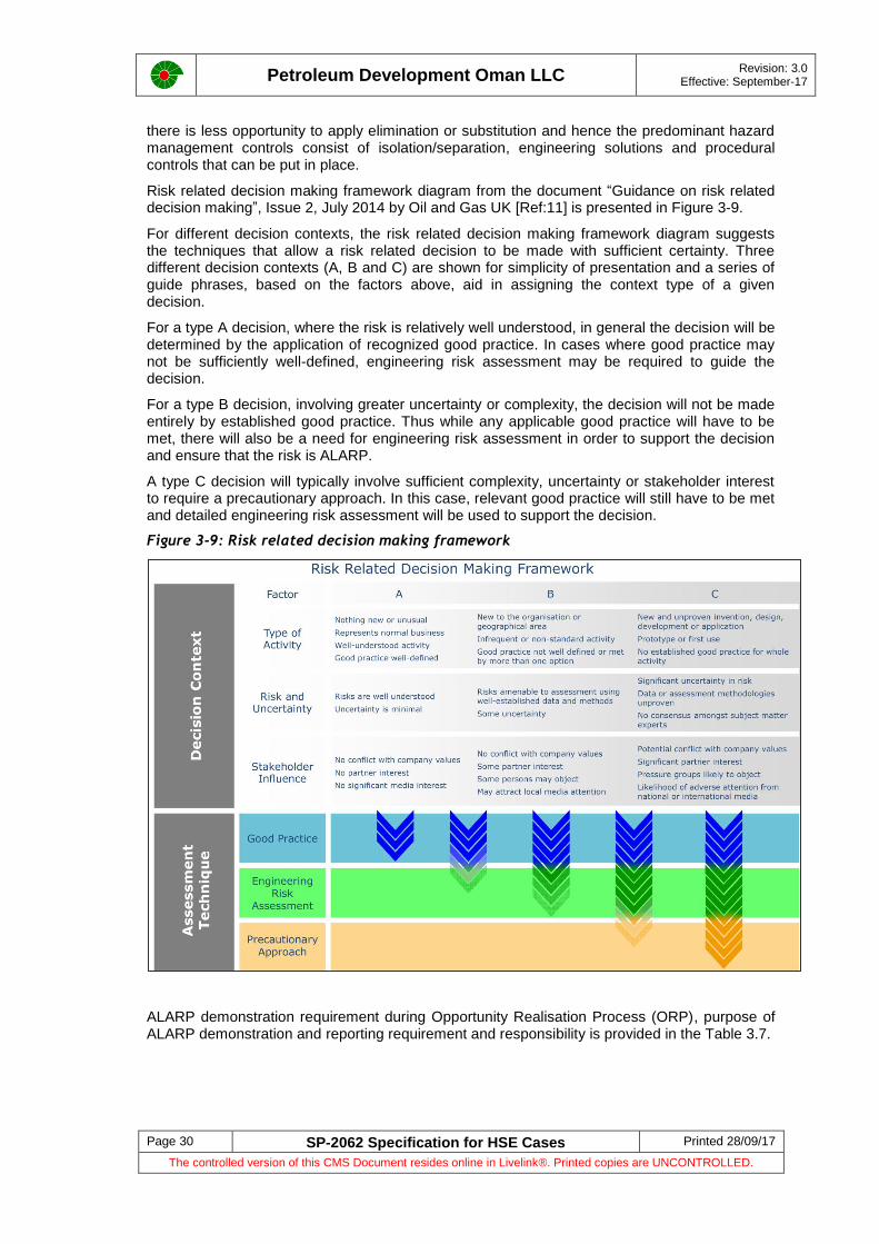
Petroleum Development Oman LLC
Revision: 3.0 Effective: September-17
Page 30 SP-2062 Specification for HSE Cases Printed 28/09/17
The controlled version of this CMS Document resides online in Livelink®. Printed copies are UNCONTROLLED.
there is less opportunity to apply elimination or substitution and hence the predominant hazard management controls consist of isolation/separation, engineering solutions and procedural controls that can be put in place.
Risk related decision making framework diagram from the document “Guidance on risk related decision making”, Issue 2, July 2014 by Oil and Gas UK [Ref:11] is presented in Figure 3-9.
For different decision contexts, the risk related decision making framework diagram suggests the techniques that allow a risk related decision to be made with sufficient certainty. Three different decision contexts (A, B and C) are shown for simplicity of presentation and a series of guide phrases, based on the factors above, aid in assigning the context type of a given decision.
For a type A decision, where the risk is relatively well understood, in general the decision will be determined by the application of recognized good practice. In cases where good practice may not be sufficiently well-defined, engineering risk assessment may be required to guide the decision.
For a type B decision, involving greater uncertainty or complexity, the decision will not be made entirely by established good practice. Thus while any applicable good practice will have to be met, there will also be a need for engineering risk assessment in order to support the decision and ensure that the risk is ALARP.
A type C decision will typically involve sufficient complexity, uncertainty or stakeholder interest to require a precautionary approach. In this case, relevant good practice will still have to be met and detailed engineering risk assessment will be used to support the decision.
Figure 3-9: Risk related decision making framework
ALARP demonstration requirement during Opportunity Realisation Process (ORP), purpose of ALARP demonstration and reporting requirement and responsibility is provided in the Table 3.7.

Petroleum Development Oman LLC
Revision: 3.0 Effective: September-17
Page 31 SP-2062 Specification for HSE Cases Printed 28/09/17
The controlled version of this CMS Document resides online in Livelink®. Printed copies are UNCONTROLLED.
Table 3-7: ALARP Demonstration requirement during opportunity realisation process
Item ALARP demonstration requirement during Opportunity Realisation Process (ORP)
Purpose of ALARP demonstration and reporting requirement Responsibility
1 ALARP demonstration during Identify and Assess Phase
To initiate opportunities and demonstrate the feasibility of those opportunities. To demonstrate that each development concept meets societal, company and technical expectations.
Early in the Opportunity Realisation Process (ORP), ALARP demonstration is focused on identification of the key risk contributors that make up the overall risk profile for each development option under consideration.
This phase also asks the question as to whether the project has looked sufficiently at all the risks, different development options, realisations and all possible outcomes. No separate ALARP demonstration report is required during Identify and Assess phase project. ALARP discussions can be captured in feasibility report.
To ensure, lessons learnt from PDO Tier 1 and Tier 2 incidents specific to project scope under consideration and lessons learnt from other completed projects are included.
Project Manager/FEDM
2 ALARP demonstration during concept select activities (During concept select activities - DG3a phase)
ALARP demonstration for selected concept during BfD stage (Basis of Design phase – DG3b phase )
Select the best option among available different options based on ALARP principle/HSE perspective. Ensure suitable design measures, safeguards are designed for the proposed project. To understand the relative risks of all remaining concepts and select the best concept solution for further development.
Where the best concept is not the lowest risk, documentation on the reasoning behind the chosen concept is a critical aspect of an ALARP demonstration. It clarifies the context in which the selection decision has been made, the data that has been used, the alternatives that have been studied, and the values and trade- offs between alternatives.
Concept select ALARP worksheet which is used to select the best concept among the available concepts can be attached as an appendix in CSR or BFD (Incase of combined CSR/BFD type of project).
The BfD forms the basis for the engineering activities in the Define phase. It is required to make sure selected concept option is robust and can be further developed safely during define stage with certainty and clarity. To identify any uncertainties associated with selected concept option and to identify mitigation plan and to check the preparedness of project for next phase.
To ensure identification of applicable DEM1 DEPs and DEM2 for project by end of select phase.
All the safety studies/deliverables generated for select phase such as HAZID, HFE, and FEA/QRA (If required) should be available for reference for ALARP demonstration workshop during BfD stage.
To ensure, lessons learnt from PDO Tier 1 and Tier 2 incidents (specific to project scope under consideration) are included in the BfD report.
Worksheet used for the ALARP demonstration for selected concept during BfD stage should be attached as an appendix in BFD report.
Concept Engineer/Project Manager
Concept Engineer/Project Manager
3 ALARP demonstration for Define phase
To take the selected concept and further define the configuration& equipment specifications and to ensure the risks are tolerable and continue to be reduced to ALARP. Project Manager is responsible to ensure activities described below are completed.
The project team should demonstrate compliance to SoF elements for projects (a, b, c, d, e, f) presented in SP-2062. SoF elements a, b, c, d, e, f are applicable for projects (Greenfield and Brownfield modification). During define stage, project may not be able to comply with all the SoF - some items in SoF element “c” “d” “e” and “f” may be still pending or ongoing).The intent of asking project to ensure compliance with SoF elements is to identify where the project stands by end of Define stage and what tasks/activities/deliverables are yet to produced to ensure safe execution of activities in next phase. If the project identifies some gap during this process, suitable action (SMART) and mitigation plan shall be developed and integrated in to project activities.
For Greenfield oil and gas projects, ALARP demonstration is an integral part of Design HSE case and shall be approved prior to VAR4.
For complex Brownfield modification project which calls for the requirement of Design HSE case, ALARP demonstration report is integral part of Design HSE case.
Approval of document (Design HSE case or Project ALARP demonstration report) shall be as per DCAF/PCAP.
Project Manager
4 ALARP demonstration for Execute Phase or Combined Define/Execute Phase (combined FEED/DD)
To complete the detailed design, procurement, fabrication, construction, installation and commission of the facility safely. Project Manager is responsible to ensure activities described below are completed.
SoF elements for projects (a, b, c, d, e, f) presented in SP-2062 shall be complied. During execute phase, project is expected to comply with all the SoF- Project elements.
For Greenfield oil and gas projects, ALARP demonstration is an integral part of Design HSE case and operation HSE case. Design HSE case done during Define Phase to be updated during execute phase for changes and to include hazards and assessment of construction/commissioning activities. Greenfield oil and gas development projects need to generate new operation HSE case or to update existing cluster/facility operation HSE case based on operation leadership decision.
For complex Brownfield modification project which calls for the requirement of Design HSE case and immediate update of operation HSE case, ALARP demonstration report is integral part of Design HSE case and operation HSE case update. However, the project team shall demonstrate compliance to SoF elements for projects (a, b, c, d, e, f) presented in SP-2062.
For off-plot delivery projects and combined FEED/DD projects, Project ALARP demonstration report shall be prepared to demonstrate compliance to SoF elements for projects (a, b, c, d, e, f) presented in SP-2062. Any impact to existing cluster or facility operation HSE case shall be documented in the project ALARP report. Project ALARP demonstration report may be a word format report or excel sheet as desired by the project team. Approval of document (Design HSE case or Project ALARP demonstration report) shall be as per DCAF/PCAP and shall be approved before PSUA.
Project Manager

Petroleum Development Oman LLC
Revision: 3.0 Effective: September-17
Page 32 SP-2062 Specification for HSE Cases Printed 28/09/17
The controlled version of this CMS Document resides online in Livelink®. Printed copies are UNCONTROLLED.
Item ALARP demonstration requirement during Opportunity Realisation Process (ORP)
Purpose of ALARP demonstration and reporting requirement Responsibility
Brief description on the preparedness and arrangements to manage emergency response during construction, commissioning and Operation Phase is an integral part of HSE cases or Project ALARP demonstration. Project should aim to complete ALARP demonstration workshop 8 to 10 months prior to potential PSUA date.
Projects to undergo Pre Start-up Audit (PSUA) and closeout all PSUA actions in line with PR-2160.
5 ALARP demonstration for Operate Phase To operate and maintain the facility in accordance with design codes and performance standards to ensure barriers remain valid. The main objective in the operational phase is to demonstrate that the risk level during operations is maintained at ALARP. In this phase of the life cycle of an asset the ability to further reduce HSSE risks is limited, however, close monitoring of HSE and Asset Integrity/ Process Safety performance is critical to ensure risks remain ALARP.
When it cannot be verified that the performance of safety critical elements (SCEs) meet the performance standards and/or when mitigation measures have been employed for extended periods to compensate for this shortfall – Statement of fitness of operation HSE case should be revalidated.
In the operate phase the documented demonstration of ALARP is often contained in the operation HSE case.
While updating 5 yearly or immediate update of operation HSE case, SoF requirement available in SP-2062 shall be completed. All SoF element (a, b, c, d, e, f, g and h) are applicable. A brief summary of scheduled and completed Level 1, Level 2 and Level 3 audit and Hardware Barrier Assessment (HBA) to be provided. Relevant findings, recommendations from Level 1, Level 2 and HBA and action closeout status shall be captured during operation HSE case update.
Lessons learnt from Tier 1 and Tier 2 incidents specific to assets included in the scope of operation HSE case shall be included while updating operation HSE case.
Asset annual Letter of Assurance (LoA) declaration to be carried out as per guidelines and templates available in GU-826 – Process Safety Letter of Assurance (LoA) Guideline [Ref.10], October 2016, Revision 1.0 or any subsequent revisions thereafter.
Statement of fitness – Asset restart following overhauls or turnaround or after any major intervention: To be dealt and complied as per PR-1721 - Shutdown Management.
Statement of fitness – Asset restart after an incident/significant event: To be dealt and complied as per PR-1418 –Incident Notification and Investigation. Requirement to complete SoF template (Different situations which calls for completing SoF) is available in Appendix 16 of GU-612 and SoF certificate is available in Appendix 4 of GU -612 Incident Notification and Investigation Guideline.
Plant modifications shall be handled as per Management of Change (MOC) process.
Process Safety Review requirements to be met as per PR-1232.
Operation Manager, DTL, Operation Safety Team Leader (OSS,GSS,ONS)
6 ALARP demonstration for specific problem resolution.
Whenever there is a requirement to make decision to choose fit for purpose control/mitigation measures among available options. To make decision to choose fit for purpose type of equipment among available types of equipment or any similar specific problem.
Applicable during Identify, Assess, Select, Define, Execute and Operation phase
Standard ALARP demonstration template to be used for documentation. Standard template should contain following elements.
Problem statement,
HSSE issues and potential risk
HSSE standards & Tolerability criteria
Options considered
Justification for chosen option
Justification for rejected option
Residual HSSE risks
Recommendation for next project phase
Recommendation for operation phase
Signature (Relevant PDO RTA and ATA based on the scope and content of ALARP demonstration)
Concept Engineer during Identify, Assess and Select phase.
Project Engineer during Define and Execute Phase
Operation Manager or representative during Operate Phase
7 ALARP demonstration for decommissioning phase or activities
As part of ALARP demonstration during decommissioning phase or projects which have decommissioning activities as part of scope of work, Hazards associated with decommissioning activities, construction activities and impacts to existing facility shall be identified and assessed. Decommissioning method statements shall be prepared by contractor and approved by PDO. Plant modifications shall be handled as per Management of Change (MOC) process. Impacts to existing POM/SOP/Drawings/Philosophy/Documents shall be identified and updated. SIMOPS MOPO, Adverse Weather MOPO, SCE Impairment and critical manpower unavailability MOPO to be carried out as part of ALARP demonstration.
Project Engineer, DTL, Operation Manager or representative
Information1: Review and approval of Project ALARP demonstration report is as per DCAF/PCAP.

Petroleum Development Oman LLC
Revision: 3.0 Effective: September-17
Page 33 SP-2062 Specification for HSE Cases Printed 28/09/17
The controlled version of this CMS Document resides online in Livelink®. Printed copies are UNCONTROLLED.
4 Statement of Fitness (SoF)
A Statement of Fitness (SoF) is required by CP-122, CP-117 and PR-2160.
Statement of fitness (SoF) types applicable for PDO with additional instructions are provided in Table 4-1. Statement of fitness – Asset restart following overhauls or turnaround or after any major intervention shall be dealt as per the requirement presented in most recent version of PR-1721. Statement of fitness – Asset restart after an incident/significant event and covering other situations requiring statement of fitness shall be dealt as per the requirement presented in most recent version of PR-1418 and GU-612 available in PDO CMF.
4.1 Purpose of SoF – Projects (Green field and Brown field/modification)
To ensure; Process safety risks have been identified, documented and are managed to As Low As Reasonably Practicable (ALARP). Employees and contractors executing HSE critical activities are competent and fit to work. Safety Critical Elements (SCEs) have been identified & SCE meets technical integrity requirements. DEM1 and DEM2 requirements are met. Procedures are in place to operate Safety Critical Element within its Operational Limits. Construction, commissioning, start-up and handover requirements are completed and ready to operate. Integrity operating envelopes have been prepared and are available. Procedures are in place to operate the safety critical elements within their operational limits. A management system is in place for the operation of the facility, operational controls, competency, maintenance and management of change. Hydrocarbons, process fluids can be safely introduced and effectively managed.
Statement of Fitness –Projects, enables operation manager and project manager in confirming that suitable control measures are indeed in place.
A Statement of Fitness - Project shall be developed for green field and brown field/modification projects prior to the Pre Start Up Audit and sets the minimum requirement. Statement of fitness element description, purpose and demonstration requirements are presented in Table 4-3.
Table 4-1: Statement of fitness types applicable for PDO
Statement of Fitness (SoF) Type Statement of Fitness (SoF) source and additional instructions
Statement of fitness – Projects
Green field development Brownfield/Modification project.
5 yearly or immediate update of operation HSE case (See Note 1)
SoF element a, b, c, d, e, f presented in Table 4-3
of SP-2062 is applicable for Green field development or Brownfield/Modification project.
While updating 5 yearly or immediate update of operation HSE case, All SoF element (a, b, c, d, e, f, g and h) presented in SP-2062 are applicable.
Statement of fitness – Asset restart following
overhauls or turnaround or after any major intervention
To be dealt and complied with PR-1721 - Shutdown Management. SoF requirements and additional
requirements are provided in PR-1721.
Statement of fitness – Asset restart after an incident/significant event
Restarting after an incident/significant event Restarting an Asset after an incident involving uncontrolled shutdown.
Restarting when the Asset has been subjected to conditions outside the operational limits
Restarting when environmental conditions experienced beyond the original design parameters.
To be dealt and complied as per PR-1418 – Incident Notification and Investigation.
Requirement to complete SoF (Different situations which calls for completing SoF) is available in Appendix 16 and SoF certificate in Appendix 4 of GU-612 Incident Notification and Investigation Guideline.
Note 1: For additional requirement, refer to Table 3-7, Item 5 – ALARP demonstration for operate phase.

Petroleum Development Oman LLC
Revision: 3.0 Effective: September-17
Page 34 SP-2062 Specification for HSE Cases Printed 28/09/17
The controlled version of this CMS Document resides online in Livelink®. Printed copies are UNCONTROLLED.
4.2 Process to obtain statement of fitness certificate – Projects
Process for obtaining statement of fitness certificate for projects (Green field and Brown field development) is established in discussion with relevant stakeholders and presented in table 4-2. The intent was to standardise the process (steps) to obtain statement of fitness certificate across PDO and to have standardised certificate. SoF Certificate for Projects is attached in Appendix 7.
Table 4-2: Process to obtain Statement of fitness certificate - Projects
Steps Description
Step 1 Generate operation HSE case (Green field development) or Project ALARP demonstration report (small projects or combined FEED/DD).
Compliance to SoF elements requirement (a, b, c, d, e, f) presented in SP-2062 is integral part of operation HSE case or Project ALARP demonstration report.
Step 2 Review and approval of operation HSE case or Project ALARP demonstration report as per DCAF/PCAP by relevant discipline Technical Authority of PDO. (See Note 1)
Step 3 Conduct Pre-start-up Audit (PSUA) and closeout of PSUA actions as per PR-2160
Step 4 Signature by Project Manager and Operations Manager on single page SoF certificate based on evidence of approved operation HSE case or Project ALARP demonstration report and closure of PSUA actions as per PR-2160 by project team.
Note 1: PDO Project engineer and ATA for operation HSE case or Project ALARP demonstration report shall ensure that reports are reviewed and approved by relevant PDO technical authorities as per DCAF/PCAP. Refer to Table 3-7, Item 3 and 4, ALARP demonstration guidance for Define, Execute Phase for additional information.
4.3 Statement of fitness elements
Statement of fitness element description, purpose, demonstration requirements are presented in Table 4-3.
Table 4-3: Statement of Fitness elements
SoF Element
SoF element description and purpose
Demonstration requirements
a Process safety risks have been identified documented and are managed to ALARP: For each phase of the Opportunity Realization Process, hazards with the potential to cause major harm to people, environment, assets (Major Accident Hazard) have been systematically identified, assessed and controlled, and plans are in place for recovery in the event control is lost. The risks associated with these hazards are tolerable and As Low As Reasonably Practicable (ALARP).
The Project must ensure that the following have been completed:
a.1. HAZID report and action closeout
a.2. Design Review and action closeout
a.3. HAZOP study and action closeout
a.4. IPF study and action closeout
a.5. Alarm rationalisation study and action closeout
a.6. FEA/FGDEA/QRA and action closeout
a.7. Bow-tie study report and action closeout
a.8. Identification of Safety Critical Element (SCE)
a.9. SIMOPs/MOPO workshop report and action closeout
a.10. Project ALARP demonstration report and action closeout
a.11. Design HSE case and Operation HSE case (If applicable)
a.12. Environmental permit requirements are analysed and necessary assessments are done and all required permits/consent are in place
a.13. Human Factor Engineering (HFE) issues identification and management

Petroleum Development Oman LLC
Revision: 3.0 Effective: September-17
Page 35 SP-2062 Specification for HSE Cases Printed 28/09/17
The controlled version of this CMS Document resides online in Livelink®. Printed copies are UNCONTROLLED.
SoF Element
SoF element description and purpose
Demonstration requirements
a.14. Occupational health risk assessment (OHRA) including noise level study (if applicable) and action closeout
a.15. Material Selection Report is prepared and approved.
a.16. Relief, Flare and Vent study and action closeout
a.17. Hazardous Area Classification drawings/Schedule prepared. Ignition source control are in place
a.18. Fit for purpose Safeguarding system is designed (F&G detection, ESD systems, Pressure relief device, Blow down and Flare system)
a.19. Flow Assurance studies and action closeout
a.20. Fire safety, fire protection and fire fighting requirements are analysed and necessary measures are incorporated in to design
a.21. Fit for purpose (safe) plant layout is designed and necessary escape route, safety equipment layout drawings are completed
a.21.1 Escape evacuation and rescue analysis and action closeout (if applicable)
a.21.2 Additional design requirements for sour and critical sour facilities are analysed and addressed as per PDO standards -SP-1190 (If applicable)
a.22. Facility Emergency Response Plan in place
a.22.1. Potential incidents related to road/marine transport of flammable, explosive and toxic substances is analysed and fit for purpose emergency response plan is in place (If applicable)
a.23. Fit for purpose (safe) Isolation requirement are designed/incorporated.
a.23.1 LO/LC register is completed by contractor and approved by PDO team.
b Employees and contractors executing safety critical activities are competent and fit to work: All assessments, studies, designs, inspections and other activities required ensuring that the facility comply with the asset integrity and process safety requirements have been completed and assured by qualified and competent people.
The Project must ensure that the following have been completed:
b.1. Contractors and Subcontractors are evaluated and approved to work for PDO projects
b.2. Employees or contractors executing Safety Critical Activities are competent and fit to work
b.3. Project has applied DCAF and PCAP is signed and followed
b.4. All deliverables (Control points) identified in PCAP are generated by project team and approved by relevant discipline Technical Authority (TA)
b.5. Project Management of Change (PMoC) is applied and process followed (If applicable)
b.6. Critical Documents and drawings are prepared and approved
b.7. DCAF deviations, Variances through Variance Tracking Tool (VTT) are applied where required
b.8. Manage changes proposed during the construction and installation phases of Projects as per PR-1153 - Field Trouble Reporting. Ensures changes are screened, reviewed and authorised to maintain the Safety and Design Integrity of the plant / facility.
c Safety Critical Equipment meets its Technical Integrity requirements: Asset register
The Project must ensure that the following have been completed:
c.1. Safety Critical Element (SCE) have been identified and

Petroleum Development Oman LLC
Revision: 3.0 Effective: September-17
Page 36 SP-2062 Specification for HSE Cases Printed 28/09/17
The controlled version of this CMS Document resides online in Livelink®. Printed copies are UNCONTROLLED.
SoF Element
SoF element description and purpose
Demonstration requirements
has been developed, the Safety Critical Elements and Design Performance Standards have been developed and integrity verified through design, procurement, construction and commissioning
registered in SAP system. Asset register has been developed.
c.1.1. Safety critical activities and safety critical roles/position are established
c.2. Performance Standards (PS) for design phase is developed and assurance , verification activities are identified for procurement, fabrication, construction and commissioning phase and approved by relevant discipline Technical Authorities (see Note under c.3)
c.3. TIV plan is prepared, TIV Report is generated and approved. [Note: To all projects below US$50 million (i.e. total Capex excl. infill
drilling) with a risk rating of Low or medium as defined in CP-223; A project-specific TIV Plan shall not be produced, Project-specific design performance standards shall not be produced, Independent verification body shall not be engaged, A project-specific TIV Report shall not be Produced.Information 2 is based on FRD-2 communication and minimum assurance tasks which needs to be done for such projects are mentioned in FRD-2 communication].
c.4. Technical integrity of SCEs are verified through assurance and verification activities for design, procurement, fabrication & construction and commissioning phase. All punch lists are closed out (for SCE related elements)
c.5. Operation phase performance standards template available with M&I are completed and Maintenance & inspection plan is set
d Design and construction of the asset (including modifications) meet the design and engineering requirements: The relevant design and fabrication standards have been identified and implemented in accordance with the Design and Engineering Manual DEM 1 and derogations authorised by the appropriate technical authority.
The Project must ensure that the following have been incorporated into the facility design or an approved derogation is in place:
d.1. Applicable DEM1 DEP are identified by end of select phase and DEM1 DEP requirements are applied/incorporated/implemented in design during FEED/DD (Define/Execute) Phase. Derogation are dealt as per DEM1 manual (if any)
d.2. As built documentation has been prepared and is available. This includes critical key documents, data and drawings that are critical to managing asset integrity and process safety
d.3. Well Handover document are completed.
e The Process Safety Basic Requirements are met: The Process Safety Basic Requirements have been addressed in accordance with the Design and Engineering Manual DEM 2.
The Project must ensure that the following have been completed:
e.1. All applicable DEM2 PSBRs (Process Safety Basic Requirements) are identified, compliance demonstrated and signed by relevant discipline TA
e.2. Approved Project to asset transfer (P2A) plan is available.
f Procedures are in place to operate Safety Critical Element within its Operational Limits:
(i) Construction, commissioning, start-up and handover requirements are completed and ready to operate.
(ii) Integrity Operating Envelopes have been prepared and are available - Procedures are in place to operate
The Project must ensure that the following have been completed:
f.1. Construction& Mechanical completion requirements are completed
f.2. Commissioning and Start-up requirements are completed
f.3. Start-up procedure prepared and approved
f.4. Handover and acceptance requirements are completed
f.5. Integrity Operating Envelopes / Variable Table / Alarm Catalogue completed and reflected in DCS
f.6. Procedures are in place to operate Safety Critical Equipment within its Operational Limits
f.7. Plant Operating Manual (or addendum to POM) are in place and are approved. As built drawings/documents are submitted by projects

Petroleum Development Oman LLC
Revision: 3.0 Effective: September-17
Page 37 SP-2062 Specification for HSE Cases Printed 28/09/17
The controlled version of this CMS Document resides online in Livelink®. Printed copies are UNCONTROLLED.
SoF Element
SoF element description and purpose
Demonstration requirements
the safety critical elements within their operational limits.
(iii) A management system is in place for the operation of the facility, operational controls, competency, maintenance and management of change. An audit and review program for that management system is in place.
to operations.
f.8. Asset Register with SCEs clearly identified, grouped as defined in the Safety Critical Element Management Manual and loaded into the Computerised Maintenance Management System. Maintenance and SCE management system populated and available. Corrosion management framework & Inspection plan in place for SCEs.
f.9 Facility Status Report (FSR) in place and updated with project status to manage Technical Integrity.
f.10. Operations Management System (OMS ) in place that covers operating procedures, alarm management, permit to work system, shift handover protocols, operator logs, overrides, temporary changes during commissioning, temporary equipment during commissioning.
f.11. The Project / Operations Readiness must ensure that the following have been completed:
f.11.1 Protection Device (Trip) settings in place for operational control of process equipment including wells.
f.11.2 Manual of Permitted Operations (MOPO)
f.12. Procedure for Emergency escape, evacuation and drills are available and relevant people are trained
f.13. Medical and first aid facilities are available
f.14. Appropriate Personal Protective Equipment (PPE)/Life saving Equipment are available and relevant staff are trained
f.15. Operations must ensure the following:
f.15.1 Competency Management framework
f.15.2 Safety Critical roles included in job description and accepted by incumbent
f.15.3 Personnel in Safety Critical roles have passed fit for work
f.16. Well Engineering must confirm the following:
f.16.1 Wells Operating Envelopes are defined
f.16.2 Wells Operational Status known and documented through Well & Reservoir Management plan
f.16.3 Wells Integrity Management defined and documented; technical well specification and technical well diagram (differences highlighted)
f.16.4 Well program and change management documentation.
f.16.5 Updated well risk register
f.16.6 Wells As-built validated
f.16.7 Wells operating envelops defined
f.16.8 Wells operational status known and documented
g Modifications are complete and have been managed via the Management of Change process.
Not applicable and not required to be filled for
g.1. Management Of Change Process is documented and Owner is identified.
g.2. Management of Change procedures are in place and are approved (Example: CP-206, PR-1001a,c,e etc)
g.3. The Management Of Change Process Owner is Responsible for
Petroleum Development Oman LLC
Revision: 3.0 Effective: September-17
Page 38 SP-2062 Specification for HSE Cases Printed 28/09/17
The controlled version of this CMS Document resides online in Livelink®. Printed copies are UNCONTROLLED.
SoF Element
SoF element description and purpose
Demonstration requirements
green field and Brownfield modification projects.
Applicable for asset modifications (e.g. Facility Change Proposals, Management of Change projects) and for the following cases.
(i) Statement of fitness – Asset restart. Following overhauls or turnaround or after any major intervention - To be dealt as per PR-1721 - Shutdown Management
(ii) Statement of fitness – Asset restart after an incident/significant event, Restarting an Asset after an incident involving uncontrolled shutdown, Restarting when the Asset has been subjected to conditions outside the operational limits, Restarting when environmental conditions experienced beyond the original design parameters – To be dealt and complied as per PR-1418 – Incident Notification and Investigation and GU-612
the following:
g.3.1. Verify that staff in Safety Critical Positions knows how to recognise the changes covered by MOC and know how to initiate the Management Of Change process and ensure appropriate training.
g.3.2. Establish and maintain documented Management Of Change Procedures to cover permanent, temporary and emergency changes, which defines Change Approval Authorities and communicates who they are. Describes the stages in the Management Of Change process and approval steps, viz:
• review and approval of the concept or proposal;
• review and approval of the design or plan, including Hazard screening and Risk analysis;
• review and approval of any scope or design changes arising during the work;
• readiness review, handover, and acceptance for use; and
• Close-out and learning capture.
g.3.3. Informs and trains the people affected by the change.
g.3.4. Manages Temporary Changes, including expiry dates and approval for extensions.
g.3.5 Manages Emergency Changes, including authorisation to postpone the Management Of Change process until control is regained.
g.4. Track the development and progress of change proposals from initiation to closeout.
g.5. Verification of effectiveness of MOC through tiered verification system and MOC included in all HSSE MS audits.
h HSE audit and inspection program test compliance with the AI-PSM and HSE Case Standards
Applicable for 5 yearly or immediate update of operation HSE case only.
Not applicable for projects and not required to be filled for green field and Brownfield modification projects.
While updating (5 yearly or immediate update) of operation HSE case, All SoF element (a, b, c, d, e, f, g and h) are applicable.
h.1. Level 1, 2 and 3 audits are scheduled and completed as per company policy. A brief summary of scheduled and completed Level 1, Level 2 and Level 3 audit to be provided.
h.2. HBA to be performed as per company policy. A brief summary of scheduled and completed Hardware Barrier Assessment (HBA) to be provided.
h.3. Relevant findings, recommendations from Level 1, Level 2 and HBA and action closeout status shall be captured during operation HSE case update.
h.4. Lessons learnt from Tier 1 and Tier 2 incidents (specific to assets included in the scope of operation HSE case) shall be included while updating operation HSE case.
h.5. Process Safety Review requirements are met as per PR-1232.

Petroleum Development Oman LLC
Revision: 3.0 Effective: September-17
Page 39 SP-2062 Specification for HSE Cases Printed 28/09/17
The controlled version of this CMS Document resides online in Livelink®. Printed copies are UNCONTROLLED.
5 Manual of Permitted Operations (MOPO)
A Manual of permitted operations (MOPO) is an information tool to assist supervisors during the planning and coordination of operations and activities by providing useful information on:
The operation or activity operating envelope and safe operating limits.
Action(s) to take if/when certain situations arise that could compromise safe operations.
The MOPO is a set of matrices that maps operational activities against foreseeable situations that if or when they arise could compromise safe operating limits – these situations are identified from:
The Threats and Escalation Factors identified as part of the Bow-tie assessments for severity 5 and red risk hazards (MAH).
An assessment of other operations and activities that could contribute to the escalation of an incident, e.g. continuing with hot work when fire pumps (a safety critical element - SCE) is/ are unavailable.
Circumstances that could compromise safe operations are grouped into three categories:
SIMOPs (Simultaneous Operations) are described as potential clash of activities which could result in undesired event having adverse effect on safety, environment, asset, schedule and reputation. SIMOPs refer to two or more potentially clashing activities /operations occurring at the same time in same place .e.g. removal or overhaul of equipment and/or production and/or construction and/or drilling in the same area (MOPO entitled SIMOPs MOPO). Project Level 4 schedule may be used to screen for potential SIMOPs and further discussed in a formal SIMOPs MOPO workshop. Team composition should include TSE, construction, commissioning, operation, maintenance representative along with project team. SIMOPs related to sour and critical sour projects/facilities require additional preparation when compared to sweet facilities and requirements as per SP-1190, SP-1258 shall be met. The complexity is further increased when there are potential clash of activities between different contractors/projects and care shall be taken to include all the stakeholders in the SIMOPs MOPO workshop.
External influences, e.g. extreme weather, visibility, security issues (MOPO entitled Adverse Weather MOPO)
Inactive safeguards and unavailability of critical manpower; i.e. SCE unavailability or impairment, e.g. ESD systems, fire fighting systems and unavailability of critical manpower, e.g. HSE critical positions, ER – team members (MOPO entitled SCE Impairment and critical manpower unavailability MOPO).
The MOPOs shall identify and differentiate between ‘stop’ (red) conditions, i.e. operation NOT permitted and what are ‘proceed with caution’ (amber) conditions, i.e. continue following appropriate risk assessment and provide additional controls where necessary. All other activities in the MOPO that do not require further assessment or controls are denoted ‘safe to proceed’ (green). For developing a new MOPO or reviewing and updating an existing MOPO, refer to Appendix 9.
5.1 Using the MOPO
Copies of the MOPO shall be readily available in a suitable format, size, laminated and displayed in the control room and other operational and job planning /coordination areas. The MOPO shall be referred to during both routine work planning and coordination and in responding to unforeseen conditions.
5.2 Deviations from the MOPO
In event of a situation arising where the preferred option is contrary to that given in the MOPO, this shall be assessed and approved by the Delivery Team Leader and relevant discipline authority. In the event of a SCE being impacted, relevant discipline authorities shall also be consulted using the FSR process.

Petroleum Development Oman LLC
Revision: 3.0 Effective: September-17
Page 40 SP-2062 Specification for HSE Cases Printed 28/09/17
The controlled version of this CMS Document resides online in Livelink®. Printed copies are UNCONTROLLED.
6 Design and Operation HSE Case content requirement
The Design and Operation HSE case content requirements are specified in Table 6-2 and these minimum requirements shall be met during the preparation and update of Design and Operation HSE case reports.
For Projects, applicable environmental permit/consent requirements and status shall be made available in part 2 of Design HSE case. Environmental management requirement for project & facilities should be dealt as per SP-2194.
The purpose of the HSE content of the Concept Selection report is to demonstrate that there has been a systematic application of HEMP during the Identify & Assess and Select Concept phases of the Opportunity Realisation Process (ORP) for each option being considered.
Brief description on the preparedness and arrangements to manage emergency response during construction, commissioning and operation phase is an integral part of HSE cases or Project ALARP demonstration.
6.1 Remedial Actions
Action items are raised during compilation of a new HSE Case or review and update of an existing HSE Case.
All action items raised should be reviewed and agreed by the action party and the HSE Case Custodian prior to entering into the HSE Case and PDO incident Management (PIM) for action tracking and close out. The HSE Case custodian and HSE case Administrator is responsible for ensuring that actions are closed out in a timely manner without value erosion. The HSE Case Custodian has overall responsibility for ensuring all technical information within the action close out is correct and complete.
Target dates are dictated by the most reasonably practicable timescale within which the actions can be completed. Table 6-1 provides guidance on Remedial Action Plan. Example Remedial Action Plan template for design and operation HSE case is provided in Appendix 6.
Table 6-1 Remedial Action Plan Guidance
Title Scope / Comments
Action No Provide action number
PIM Action Item No. Action item number as assigned once entered into the PIM database
Bow-Tie Ref Reference number of Bow-Tie diagram
Action Description Description of action
Strategy to Achieve an Action
Strategy to achieve action
Measure / Indicator Measures and indicators to assess progress and completion of the action
Comments / Status Comments / Status

Petroleum Development Oman LLC
Revision: 3.0 Effective: September-17
Page 41 SP-2062 Specification for HSE Cases Printed 28/09/17
The controlled version of this CMS Document resides online in Livelink®. Printed copies are UNCONTROLLED.
Table 6-2 Design and Operation HSE Case content requirements
Design HSE case – Content requirement Operation HSE case – Content requirement
Part 1 Introduction
Part 1 shall:
Describe the scope and purpose of the Design HSE Case
Include brief project summary
Summarise review and update requirements.
Statement of fitness requirement and compliance
Part 1 Introduction
Part 1 shall:
Describe the scope and purpose of the operation HSE Case
Summarise review and update requirements.
Statement of fitness requirement and compliance
Part 2 Concept Select ALARP demonstration Summary
Part 2 shall contain:
A summary of the ALARP demonstration in the Concept Select Report which describes the process from the Identify & Assess phase to the Select phase and the selection of the chosen concept. This includes a list of supporting safety studies undertaken.
Environmental permit/consent requirements applicable for project and status
Part 2 Facility Description
Part 2 shall contain:
A detailed description of the facility, including plant layout, material selection, safety system, process systems, utilities, including manning levels, interfaces to show boundaries of the operation HSE Case
A list of the MAHs associated with the facilities, A list of all safety critical elements (SCE) – defined as hardware barriers on the bow-ties
A list of projects which were commissioned recently and list of ongoing projects (Applicable in case of a 5 year or immediate operation HSE case update)
Part 3 Design Basis & Project Description
Part 3 shall contain:
A detailed description of the chosen concept, including site selection, plant layout, material selection, manning philosophy, project overview to show boundaries of the design HSE Case
A list of all DEPs, codes, standards and specifications used in the design
A Variance Tracking Register or reference to it, briefly providing justification why the engineering standards or specifications for the project deviate from applicable Design Engineering practices (DEP) and status.
A list of the Major Accident Hazard (MAH) associated with the project facilities
A list of all safety critical elements (SCE) – Identified as hardware barriers on the bow-ties
Part 3 People& HSE Critical activities/Tasks
Part 3 shall contain:
Normal operation facility manning levels and listing of key positions
Organisational structure and highlighting all personnel within the Operations HSE Case who hold an HSE Critical Position/Role, i.e. they have HSE critical activities/ tasks assigned to them.
A brief description of the HSE Critical Task and link to the specifications and procedures, documenting how the HSE Critical Task is implemented. The means by which the HSE Critical Task is assured. Refer to section 3.8 and Appendix 8.
Part 4 Hazard and Effects Management Process
Part 4 shall contain:
Preferably in a tabular format (studies, scope, recommendation, references, action closeout status) Summary of HEMP studies undertaken e.g. Hazard Identification studies (HAZID), Hazard and Operability studies (HAZOP), Instrumented Protective Function (IPF), plant layout study, Quantified Risk Assessment (QRA), Health Risk Assessment (HRA) Human Factors Engineering (HFE), consequence modelling, Escape evacuation and rescue analysis (EERA), SAFOP, Fire protection design. DEM1 and DEM2 compliance.
Bow-Tie diagrams for severity 5 and red risk on PDO RAM in line with Shell global bow-tie guidance and criteria set in SP-2062 and remedial action/shortfall.
Details of utilised HSE Risk Tolerability, Acceptance Criteria and ALARP Framework.
A Hazard and Effects Register containing details of all hazards (assessed using the PDO risk assessment matrix) and using the format specified in SP-2062. This can be attachment.
A summary of practical risk reduction measures and their implementation status.
Any issues that may have an impact on the risk profile and so need to be addressed during detail engineering, construction, commissioning and the Operate phase.
Emergency Response Management – Briefly explaining the preparedness and arrangements to manage emergency response during construction, commissioning and Operation Phase.
Suitable references to be provided.
Part 4 Hazard and Effects Management Process
Part 4 shall contain:
Preferably in a tabular format (studies, scope, date conducted, recommendation, action closeout status, remarks) Summary of HEMP studies undertaken and e.g. Hazard Identification studies (HAZID), Hazard and Operability studies (HAZOP), Instrumented Protective Function (IPF), plant layout study, Quantified Risk Assessment (QRA), Health Risk Assessment (HRA) Human Factors Engineering (HFE), consequence modelling, Escape evacuation and rescue analysis (EERA), SAFOP, Fire protection design. DEM1 and DEM2 compliance.
A Hazards and Effects Register containing all hazards identified for the facility/operations are to be listed and assessed using the PDO risk assessment matrix. The severity 5 and red risk hazards contain references to the relevant Bow-Tie diagrams
Bow-Tie diagrams for severity 5 and red risk on PDO RAM in line with Shell global bow-tie guidance and criteria set in SP-2062 and remedial action/shortfall. Details of utilised HSE Risk Tolerability, Acceptance Criteria and ALARP Framework.
A matrix of permitted operations (MOPO) to define the operating envelope and safe operating limits for the facility and provide guidance on action required in event of abnormal situations. Situations mapped shall cover:
Adverse weather conditions MOPO
Simultaneous operations (SIMOPs) MOPO
Safety critical element (SCE) and critical manpower unavailability MOPO
Emergency Response Management – Briefly explaining the preparedness and arrangements to manage emergency response.
Suitable references to be provided.
Part 5 Remedial Action Plan
Part 5 shall contain
An action plan that is SMART (specific, measurable, agreed, realistic and time bound) which lists all the actions to be carried forward to next project phase.
Following approval of HSE case custodian, the open action items shall then be entered into the PDO action tracking system to be formally tracked and closed out. PDO Incident Management (PIM) system is used for tracking actions from HSE Cases.
Part 5 Remedial Action Plan
Part 5 shall contain:
An action plan that is SMART (specific, measurable, agreed, realistic and timely) which lists all the actions raised during the development of the Operations HSE Case or update of operation HSE case.
All action items shall be entered into the PDO action tracking system to be formally tracked and closed out once they have been fully approved by the HSE Case Custodian. PDO Incident Management (PIM) is used for tracking actions from PDO HSE Cases.
Update of Design HSE case during executes Phase: Design HSE case is updated to changes during execute phase and shall include construction/commissioning hazards and assessment in Par t4: Hazard and Effect Management Process.
Immediate or 5 yearly update of operation HSE case during execute phase/operate phase will not call for additional content requirement. HSE case content requirement specified for operation HSE case is sufficient.

Petroleum Development Oman LLC
Revision: 3.0
Effective: September -17
Page 42 SP-2062 Specification for HSE Cases Printed 28/09/17
The controlled version of this CMS Document resides online in Livelink®. Printed copies are UNCONTROLLED.
Appendix 1 Glossary of Definitions, Terms and Abbreviations
Acronym Definition
AI-PSM Asset Integrity - Process Safety Management
ALARP As Low As Reasonably Practicable
ATA Accountable Technical Authority
BfD Basis for Design
CFDH Corporate Functional Discipline Head
CSR Concept Selection Report
DBOOM Design Build Own Operate Maintain
DBOOT Design Build Own Operate Transfer
DCAF Discipline Controls and Assurance Framework
DD Detail Design
DEP Design Engineering Practise
DG Decision Gate
DTL Delivery Team Lead
FEDM Front End Development Manager
FEED Front End Engineering and Design
FERM Fire and Explosion Risk Management study
FID Final Investment Decision
FSR Facility Status Report
GHG Green House Gas
HAZID Hazard Identification
HAZOP Hazard and Operability study
HBA Hardware Barrier Assessment
HEMP Hazards and Effects Management Process
HFE Human Factors Engineering
HSE Health, Safety and Environment
HSE-MS Health, Safety and Environment Management System
HSSE Health, Safety, Security and Environment
IADC International Association of Drilling Contractors
IPF Instrumented Protective Function
LOA Letter of Assurance
MAH Major Accident Hazard
MIE Maintenance Integrity Execution
MOPO Manual of Permitted Operations
ORP Opportunity Realisation Process
PCAP Project Control Assurance Plan
PEFS Process Engineering Flow Schematics
PSBR Process Safety Basic Requirements
PSUA Pre-Start Up Audit
PTW Permit to Work
QRA Quantitative Risk Assessment

Petroleum Development Oman LLC
Revision: 3.0
Effective: September -17
Page 43 SP-2062 Specification for HSE Cases Printed 28/09/17
The controlled version of this CMS Document resides online in Livelink®. Printed copies are UNCONTROLLED.
Acronym Definition
RAM Risk Assessment Matrix
SCE Safety Critical Element
SMART Specific, Measurable, Agreed, Realistic and Time bound
SoF Statement of Fitness
TA Technical Authority
VAR Value Assurance Review
Barrier Barriers prevent or reduce the probability of Threat (left hand side of the bow-tie), limit the extent of, of provide immediate recovery from the Consequences (right hand side of the bow-tie).
A barrier may be hardware, or human interventions also called human barriers or a combination of both. Hardware barriers are equipment, hardware or safety systems also called as a “Safety Critical Element” (see SCE). These barriers are act to prevent top events or mitigate the consequences of a top event.
Human barriers rely on a human being as part of the barrier, initiating or taking actions in response to information to prevent the top event or mitigate the consequences. Human barriers in practice are often used in combination with hardware to perform an action ( e.g., an operator response to alarm, initiating emergency response)
Consequence A consequence is an effect on People, Assets, Environment or reputation as result of hazard being released. A consequence is the ultimate credible harm that may occur as a result of the release of a hazard.
Escalation Factor Escalation Factors are situations, conditions or circumstances that defeat, degrade, impair or reduce the effectiveness of a Barrier or Recovery Preparedness Measures.
Escalation Factor Control Measures put into place to prevent or mitigate the effects of Escalation Factors from adversely affecting a Barrier or Recovery Preparedness Measures
Safety Critical Element (SCE) A Safety Critical Element (SCE) is any item of hardware, structure, system or logic software the failure of which could cause a Major Accident Hazard (MAH) or whose purpose is to prevent or control, mitigate the effects of a MAH. Safety Critical Element (SCE) has the same meaning of HSE Critical Element.
Safety critical activities/ HSSE critical activities
A group or set safety critical tasks necessary for the development, implementation, operation and or maintenance of a barrier or recovery preparedness measures or escalation factor control established for managing hazards with red risk on PDO RAM or Yellow 5A/5B risks (Major Accident Hazards).
Safety Critical (HSE critical) position
Personnel positions having the responsibility to design, implement, operate/maintain a barrier or recovery preparedness measures or escalation factor control established for managing hazards with red risk on PDO RAM or Yellow 5A/5B risks (Major Accident Hazards). In simple words, HSE critical position personnel are those who execute or perform HSE critical activities/tasks.
Safety Critical (HSE critical) processes:
A management process established to design, implement, operate/maintain a barrier or recovery preparedness measures or escalation factor control established for managing hazards with red risk on PDO RAM or Yellow 5A/5B risks (Major Accident Hazards). Examples are Management of Change, PTW system, Emergency Response, Competency management, Contractor management, DCAF, Wells integrity management, Incident investigations, HSE management system, Facility Status Report (FSR) Corrosion management, etc.
Recovery Preparedness Measure Any measure put in place to limit or mitigate consequences and assist recovery from a Top Event. Located on the right hand side of a Bow-Tie
Threat A threat is the occurrence (condition, situation, phenomenon or event) which will release the hazard and cause a Top event.
Tolerable risk Tolerable Risks are those that have been reduced to a level where they comply with the applicable laws and regulations, standards, strategic objectives and other agreed Tolerability Criteria.
Top event First event that occurs when a hazard is releases, such as release of hydrocarbons, toxic substances or energy. Typically, top events are loss of containment, loss of control or release of energy.

Petroleum Development Oman LLC
Revision: 3.0
Effective: September -17
Page 44 SP-2062 Specification for HSE Cases Printed 28/09/17
The controlled version of this CMS Document resides online in Livelink®. Printed copies are UNCONTROLLED.
Appendix 2 References
1. International Association of Drilling Contractors (IADC) Drilling Contractors, Health, Safety and Environment Case Guidelines for Land Drilling Contractors, Issue 1.0.1, 27 July 2009. http://www.iadc.org/iadc-hse-case-guidelines/
2. PDO AIPSM Incident data book.
http://portal.corp.pdo.om/solutions/LKB/MSE/AIPSM/Pages/HomePage.aspx
3. ISO 17776, First edition 2000, Guideline on tools and techniques for hazard identification and risk assessment.
4. ISO 17776, draft, 2015, Major Accident Hazard (MAH) management during the design of new installations.
5. Shell Global Bow-Tie Guidance, Issue date: December 11, 2015, Document revision: 0
6. Safety Critical Element Management Manual, SR.14.11269
7. SP-1231, Occupational Health Specification
8. Ageing Plant Operational Delivery Guide, Control of Major Accident Hazards (COMAH), Version 1, June 2010.
9. Managing ageing plant – A summary guide. HSE, UK.
10. GU-826 – Process Safety Letter of Assurance (LoA) Guideline
11. Guidance on risk related decision making, Issue 2, July 2014 by Oil and Gas UK

Petroleum Development Oman LLC
Revision: 3.0
Effective: September -17
Page 45 SP-2062 Specification for HSE Cases Printed 28/09/17
The controlled version of this CMS Document resides online in Livelink®. Printed copies are UNCONTROLLED.
Appendix 3 Hazard Identification (HAZID) Checklist
Hazard Ref. No. Hazard category and description Potential source, issues
H-01 Hydrocarbons
H-01.01 Oil under pressure Flowlines, pipelines, pressure vessels and piping
H-01.02 Hydrocarbons in formation Oil wells especially during well drilling and entry/work over operations
H-01.03 LPGs (e.g. propane, butane) Process fractionating equipment, storage tanks, transport trucks and rail cars
H-01.04 LNGs Cryogenic plants, tankers
H-01.05 Condensate, NGL Gas wells, gas pipelines, gas separation vessels
H-01.06 Hydrocarbon gas Oil/gas separators, gas processing plants, compressors, gas pipelines
H-01.07 Oil at low pressure Oil storage tanks
H-01.08 Wax Filter separators, well tubulars, pipelines.
H-01.09 Coal Fuel source, mining activities
H-02 Refined Hydrocarbons
H.02.01 Lube oil and seal oil Engines and rotating equipment
H.02.02 Hydraulic oil Hydraulic pistons, hydraulic reservoirs and pumps
H.02.03 Diesel fuel Fuel, vehicles fuelling stations, vehicle maintenance, storage at process plant and construction site
H.02.04 Petroleum spirit/gasoline Vehicles fuelling stations, vehicle maintenance
H-02.05 Kerosene's / Jet Fuels Aircraft, portable stoves, portable lanterns, heating systems, storage tanks.
H-02.06 Heavy Fuel Oils Shipping fuel, bunkers, heating systems, storage tanks.
H-02.07 Bitumen's and Bitumen Derivatives Road construction.
H-03 Other flammable materials
H.03.01 Cellulosic materials Packing materials, wood planks, paper rubbish
H.03.02 Pyrophoric materials Metal scale from vessels in sour service, scale on filters in sour service, iron sponge sweetening units
H-04 Explosives
H-04.01 Detonators Seismic operations, pipeline construction.
H-04.02 Conventional Explosive Material Seismic operations, pipeline construction, blasting, platform decommissioning
H-04.03 Perforating gun charges Well completion activities associated with drilling rigs and work over operations
H-04.04 Military Ordnance Spent ammunitions, land mines, depleted uranium rounds, improvised explosive devices.
H-05 Pressure hazards
H-05.01 Bottled gases under pressure Welding and metal cutting operations, laboratory gas sources, diving operations (air bottle)
H-05.02 Water under pressure in pipe works Water disposal, water floods and injection operations, strength testing of pipe works, well fracturing and treatments.
H-05.03 Non-hydrocarbon gas under pressure in pipe works
Purging and leak testing of facilities
H-05.04 Air under high pressure Seismic air guns and related piping
H-05.05 Hyperbaric Operations (Diving) Diving - Under sea operations
H-05.06 Vacuum Tanks, accumulators.
H-05.07 Hypobaric Operations Working at high altitude (generally >2000m).
H-06 Hazards associated with differences in Height
H-06.01 Personnel at Height >2m Working on scaffolding, suspended access, ladders, platforms, excavations, towers, stacks, roofing, working overboard, working on monkey board.
H-06.02 Personnel at Height <2m Slippery/uneven surfaces, climbing/descending stairs, obstructions, loose grating.
H-06.03 Overhead equipment Objects falling while being lifted/handled or working at a height over people, equipment or process systems, elevated work platforms, slung loads, hoists.
H-06.04 Personnel under water Objects falling onto divers from operations overhead
H-06.05 Personnel below grade Pipeline trenches, excavations, repairing buried facilities.
H-07 Objects under Induced Stress
H-07.01 Objects under Tension Guy and support cables, anchor chains, tow & barge tie-off ropes, slings.
H-07.02 Objects under Compression Spring-loaded devices such as relief valves and actuators and hydraulically operated devices.
H-08 Dynamic Situations hazards
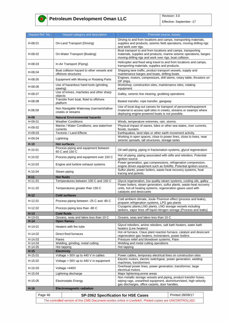
Petroleum Development Oman LLC
Revision: 3.0
Effective: September -17
Page 46 SP-2062 Specification for HSE Cases Printed 28/09/17
The controlled version of this CMS Document resides online in Livelink®. Printed copies are UNCONTROLLED.
Hazard Ref. No. Hazard category and description Potential source, issues
H-08.01 On-Land Transport (Driving) Driving to and from locations and camps, transporting materials, supplies and products, seismic field operations, moving drilling rigs and work over rigs.
H-08.02 On-Water Transport (Boating) Boat transport to and from locations and camps, transporting materials, supplies and products, marine seismic operations, barges moving drilling rigs and work over rigs, boat collision.
H-08.03 In-Air Transport (Flying) Helicopter and fixed wing travel to and from locations and camps, transporting materials, supplies and products.
H-08.04 Boat collision hazard to other vessels and offshore structures
Shipping lane traffic, product transport vessels, supply and maintenance barges and boats, drifting boats.
H-08.05 Equipment with Moving or Rotating Parts Engines, motors, compressors, drill stems, rotary table, thrusters on DP ships.
H-08.06 Use of hazardous hand tools (grinding, sawing)
Workshop, construction sites, maintenance sites, rotating equipment
H-08.07 Use of knives, machetes and other sharp objects
Galley, seismic line clearing, grubbing operations
H-08.08 Transfer from boat, flotel to offshore platform
Basket transfer, rope transfer, gangway
H.08.09 Non Navigable Waterway (narrow/shallow creeks or streams
Use of local dug-out canoes for transport of personnel/equipment /material to access spill sites in creeks, streams or swamps where deploying engine-powered boats is not possible.
H-09 Natural Environmental hazards
H-09.01 Weather Conditions Winds, temperature extremes, rain, storms.
H-09.02 Marine / Water Conditions, sea state/river currents
Physical impact of waves, tides or other sea states, river currents, floods, tsunami.
H-09.03 Tectonic / Land Effects Earthquakes, land slips or other earth movement activity.
H-09.04 Lightning Working in open spaces, close to power lines, close to trees, near seismic spreads, tall structures, storage tanks
H-10 Hot surfaces
H.10.01 Process piping and equipment between 60 C and 150 C
Oil well piping, piping in fractionation systems, glycol regeneration
H.10.02 Process piping and equipment over 150 C Hot oil piping, piping associated with stills and reboilers. Potential ignition source.
H.10.03 Engine and turbine exhaust systems Power generation, gas compressions, refrigeration compression, engine driven equipment such as forklifts. Potential ignition source.
H.10.04 Steam piping Sulfur plants, power boilers, waste heat recovery systems, heat tracing and jackets.
H.11 Hot fluids
H-11.01 Temperatures between 100 C and 150 C Glycol regeneration, low quality steam systems, cooling oils, galley
H-11.02 Temperatures greater than 150 C Power boilers, steam generators, sulfur plants, waste-heat recovery units, hot-oil heating systems, regeneration gases used with catalysts and desiccants
H-12 Cold surfaces
H-12.01 Process piping between -25 C and -80 C Cold ambient climate, Joule-Thomson effect (process and leaks), propane refrigeration systems, LPG gas plants
H-12.02 Process piping less than -80 C Cryogenic plants,LNG plants, LNG storage vessels including tankers, vapor lines off liquid nitrogen storage (Process and leaks)
H-13 Cold fluids
H-13-01 Oceans, seas and lakes less than 10 C Oceans, seas and lakes less than 10 C
H-14 Open flames
H-14.01 Heaters with fire tube Glycol reboilers, amine reboilers, salt bath heaters, water bath heaters (Line heaters)
H-14.02 Direct fired furnaces Hot oil furnace, Claus plant reaction furnace, catalyst and desiccant regeneration gas heaters, incinerators, power boilers
H-14.03 Flares Pressure relief and blowdown systems, Flare
H-14.04 Welding, grinding, metal cutting Welding and metal cutting operations
H-14.05 Hot tapping Hot tapping
H-15 Electricity
H-15.01 Voltage > 50V up to 440 V in cables Power cables, temporary electrical lines on construction sites
H-15.02 Voltage > 50V up to 440 V in equipment Electric motors, electric switchgear, power generation, welding machines, transformers
H-15.03 Voltage >440V Overhead power lines, power generation, transformer, large electrical motors
H-15.04 Lightning discharge Major lightening-prone areas
H-15.05 Electrostatic Energy Non metallic storage vessels and piping, product transfer hoses, wiping rags, unearthed equipment, aluminium/steel, high velocity gas discharges, office carpets, door handles.
H-16 Electromagnetic radiation

Petroleum Development Oman LLC
Revision: 3.0
Effective: September -17
Page 47 SP-2062 Specification for HSE Cases Printed 28/09/17
The controlled version of this CMS Document resides online in Livelink®. Printed copies are UNCONTROLLED.
Hazard Ref. No. Hazard category and description Potential source, issues
H-16.01 Ultraviolet radiation Arc welding, sunshine
H-16.02 Infrared radiation Flares
H-16.03 Microwaves Galley
H-16.04 Lasers Instrumentation, surveying
H-16.05 E/M radiation: High voltage AC cables Transformers, power cables.
H-17 Ionising radiation, open source
H-17.01 Alpha, Beta, open source Well logging, radiography, densitometers, interface instruments.
H-17.02 Gamma Rays, open source Well logging, radiography.
H-17.03 Neutron, open source Nuclear reactors, well logging.
H-17.04 Naturally Occurring Ionising Radiation (NORM)
Scales in tubulars, vessels and process plant fluids (especially in C3 reflux streams), mining activity oil/gas/coal/mineral sands, phosphates, recycled scrap steel.
H-18 Ionising radiation, closed source
H-18.01 Alpha, Beta, closed source Well logging, radiography, densitometers, interface instruments.
H-18.02 Gamma Rays, closed source Well logging, radiography.
H-18.03 Neutron, closed source Well logging.
H-19 Asphyxiates
H-19.01 Insufficient oxygen atmosphere Confined spaces, tanks
H-19-02 Excessive CO2 Areas with CO2 fire fighting systems, turbine enclosures
H-19-03 Drowning Water transport, marine seismic operations, diving
H-19-04 Excessive N2 N2 purges vessels
H-19-05 Halon Areas with halon fire fighting systems, turbine enclosures, electrical switchgear and battery rooms
H-19-06 Smoke Welding/burning operations, fires
H-20 Toxic gas
H-20.01 H2S (Hydrogen sulphide, sour gas) Sour gas production, confined spaces I sour operations, bacterial activity in stagnant water
H-20.02 Exhaust fumes Sleeping in cars with running engines, heating devices, car garage
H-20.03 SO2 Flaring H2S gas and incinerator flue gas
H-20.04 Benzene Component of crude oil, concentrated in glycol vent emissions
H-20.05 Chlorine Water treatment facilities
H-20.06 Welding fumes Construction and metal fabrication/repair, welding toxic metals (galvanised steel, cadmium-coated steel), metal cutting, grinding
H-20.07 Tobacco smoke Accommodation, office buildings, inside cars
H-20.08 CFCs Air conditioning, refrigeration, aerosol sprays
H-21 Toxic liquid
H-21.01 Mercury Electrical switches, Gas filters, Processing units, mercury removal units, waste
H-21.02 PCBs Transformer cooling oils
H-21.03 Biocide Water treatment facilities
H-21.04 Methanol Gas drying and hydrate control
H-21.05 Brines Hydrocarbon production, well kill fluid, packer fluids.
H-21.06 Glycols Gas drying and hydrate control
H-21.07 Degreasers (tarpenes) Maintenance shops
H-21.08 Isocyanates Two-pack paint systems
H-21.09 Sulfanol Gas sweetening.
H-21.10 Amines Gas sweetening.
H-21.11 Corrosion Inhibitors Additive to pipelines and oil/gas wells; chromates, phosphates.
H-21.12 Scale inhibitors Cooling and injection water additive
H-21.13 Liquid mud additives Drilling fluid additive
H-21.14 Odorant Additives (mercaptans) Custody transfer facilities for gas, LPG and LNG.
H-21.15 Used engine Oils (polycyclic aromatic hydrocarbons)
Used engine oils
H-21.16 Carbon Tetrachloride Laboratory
H-21.17 Grey and or black water septic systems, camps, detergents
H-22 Toxic solids
H-22.01 Asbestos Thermal insulation and construction materials, old roofing (encountered during removal)
H-22.02 Man-made mineral fibre Thermal insulation and construction materials
H-22.03 Cement dust Oil well and gas well cementing, civil construction
H-22.04 Sodium hypochlorite Drilling fluid additive
H-22.05 Powdered mud additives Drilling fluid additive
H-22.06 Sulfur dust Sulfur recovery plants
H-22.07 Pig trash Pipeline cleaning operations
H-22.08 Oil based muds Oil and gas well drilling
H-22.09 Water based muds Oil and gas well drilling

Petroleum Development Oman LLC
Revision: 3.0
Effective: September -17
Page 48 SP-2062 Specification for HSE Cases Printed 28/09/17
The controlled version of this CMS Document resides online in Livelink®. Printed copies are UNCONTROLLED.
Hazard Ref. No. Hazard category and description Potential source, issues
H-22.10 Cement slurries Oil and gas well drilling, construction
H-22.11 Dusts Cutting brickwork and concrete, driving on unpaved roads, carpenter shops, grit blasting, sand blasting, catalyst (dumping, removal)
H-22.12 Cadmium compounds and other heavy metals
Welding fumes, handling coated bolts
H-22.13 Oil based sludges Oil storage tank cleaning
H-23 Corrosive substances
H-23.01 Hydrofluoric acid Well stimulation
H-23.02 Hydrochloric acid Well stimulation
H-23.03 Sulfuric acid Wet batteries, laboratory
H-23.04 Caustic soda (Sodium hydroxide) Drilling fluid additive
H-24 Biological Hazards
H-24.01 Poisonous plants(e.g. poison ivy and oak, stinging nettles, nightshade)
Natural environment
H-24.02 Large animals (e.g. dogs, cats, rats, wild animals)
Natural environment
H-24.03 Small animals (snakes, scorpions, lizards) Natural environment
H-24.04 Food-borne bacteria (e.g. e-coli) Contaminated food
H-24.05 Water-borne bacteria (e.g. legionella) Cooling systems, domestic water systems
H-24.06 Parasitic insects (e.g. pin worms, bed bugs, Lice, fleas)
Improperly cleaned food, hands, clothing, living sites, camps
H-24.07 Disease - transmitting insects (mosquitoes, malaria and yellow fever; ticks: lime diseases;fleas:plague)
Natural environment
H-24.08 Cold and flu viruses Infected people
H-24.09 Human immune deficiency virus (HIV) Contaminated blood, body fluids
H-24.10 Other communicable diseases Infected people
H-25 Ergonomic hazards
H-25.01 Manual materials handling Pipe handling on drill floor, sack handling in sack store, maneuevring equipment in awkward locations
H-25.02 Damaging noice Releases from relief valves, pressure control valves
H-25.03 Loud steady noice>85 dBA Engine rooms, compressor rooms, drilling brake, air tools
H-25.04 Heat stress (High ambient temperatures) Near flare, on the monkey board under certain conditions, in open exposed areas in certain regions of world during summer.
H-25.05 Cold stress (Low ambient temperatures) Open areas in winter in cold climates, refrigerated storage areas
H-25.06 High humidity Climates where sweat evaporation rates are too low to cool the human body, wearing personal protective clothing
H-25.07 Vibration Hand tool vibration, maintenance and construction work, boating
H-25.08 Workstations Poorly designed office furniture and poorly laid out workstations
H-25.09 Lighting Work areas requiring intense light, glare, insufficient light
H-25.10 Incompatible hand controls Controls poorly positioned in workplace requiring workers to exert excessive force, lacking proper labels, hand operated control valves
H-25.11 Awkward location of workplaces and machinery
Machinery difficult to maintain regularly due to their awkward positioning. E.g. valves in an usually high or low positions
H-25.12 Mismatch of work to physical abilities Requiring older workers to maintain a high physical level of activity over the course of an 8-12 hour work day, heavy construction work performed by slight individuals
H-25.13 Mismatch of work to cognitive abilities Requiring individuals to monitor a process without trying to reduce their boredom by giving them a higher task load, asking a worker to supervise something he/she is not qualified to do
H-25.14 Long and irregular working hours/shifts Utilizing long shift cycles, overtime, night shifts
H-25.15 Poor organization and job design Ambiguity of job requirements, unclear reporting relationships, over/under supervision, poor operator/contractor interfaces
H-25.16 Work planning issues Work overload, unrealistic targets, lack of clear planning, poor communications
H-25.17 Indoor climate (too hot, cold, dry, humid) Uncomfortable climate for permanently manned areas
H-26 Psychological hazards
H-26.01 Living on the job/away from family, fatigue Home sickness, missing family and social events, feeling of isolation
H-26.02 Working and living on a live plant Awareness that mistakes can be catastrophic, vulnerable to the mistakes of others, responsible for safety of others, emergency situations
H-26.03 Post- traumatic stress Serious incidents, injuries to self and others
H-26.04 Psychological stress/fatigue Poorly managed workers camps and welfare activities/program
H-27 Security related hazards
H-27.01 Piracy Sea pirates

Petroleum Development Oman LLC
Revision: 3.0
Effective: September -17
Page 49 SP-2062 Specification for HSE Cases Printed 28/09/17
The controlled version of this CMS Document resides online in Livelink®. Printed copies are UNCONTROLLED.
Hazard Ref. No. Hazard category and description Potential source, issues
H-27.02 Assault Assault, violence against an individual.
H-27.03 Sabotage Disgruntled employee, sabotage
H-27.04 Crisis Military action, civil disturbances, terrorism
H-27.05 Theft of Sensitive Information and materials
Deliberate, targeted espionage and loss of commercially sensitive information, documents, plans, financials, telephone conversations, email loss, materials in yards
H-28 Use of natural resources and discharge
H-28.01 Land Installation sites, drilling locations, seismic clearing, pipeline rights of way
H-28.02 Water Cooling water
H-28.03 Air Turbines, combustion engines (cars, trucks, pump and compressor drivers)
H-28.04 Trees, vegetation Installation sites, drilling locations, seismic clearing, pipeline rights of way
H-28.05 Gravel Borrow pits, road construction
H-28.06 Discharge to water Produced water, sewage systems, seepage of liquids to ground water
H-28.07 Discharge to land Waste disposal including domestic, industrial (pig trash, oil based tank sludges, medical and hazardous waste)
H-28.08 Discharge to air/air emissions Discharge of chemicals to air, venting, fugitive emissions, exhaust, flare stack, dusts, particulate and smoke
H-29 Social Performance
H-29.01 Procurement Philosophy Supply chain management, local purchasing, employment and labour.
H-29.02 Revenue Streams Revenue transparency and revenue streams, equity, socio-economic changes, corruption.
H-29.03 Land Take Land right entitlement, resettlement, loss/change of livelihood.
H-29.04 Temporary Project (e.g. construction) Change in makeup of population, boom-bust, social services, large workforces, disturbance impacts, archaeological sites, cultural and sacred sites, flourishing of shanty towns and mammy markets.
H-29.05 (Lack of) Engagement Changes in power relations, community decision making structures and skills, high expectations, vulnerable groups, conflict, human rights, perceived health and environmental impacts.
H-29.06 Conflicting Use for Resources High prices paid for local commodities, use of local labour and talent, use of local accommodation, transportation, infrastructure.
H-30 Medical
H-30-01 Medical unfitness Staff medically unfit for the task
H-31 Noise
H-31.01 High level noise Plant areas, e.g. turbines, compressors, generators, pumps, blowdown, etc
H-31.02 Intrusive noise Intrusive noise in sleeping areas, offices and recreational areas
H-32 Entrapment
H-32.01 Fire, explosion, flammable and toxic release
Blockage of routes to muster location or contamination of muster areas. Unable to perform emergency response activities.
H-32.02 Mechanical damage Objects blocking access to escape routes, person in locked rooms
H-33 Human Factor Engineering hazards
H-33.01 Control room design Poorly designed control rooms
H-33.02 Manual Valve Operation Manual Valves/critical valves in awkward position, difficult to access, operate/maintain
H-33.03 Human Machine Interface Poor design of Human Machine Interface, difficult to operate/maintain
H-33.04 Skid packages Poor design, access issues, difficult to operate and maintain
H-33.05 HFE for Safety Critical Tasks Poor design, access issues, difficult to operate and maintain, Safety critical tasks are not identified.
H-33.06 Workspace design Poor workspace design
H-33.07 Equipment and Facilities labelling No Equipment and Facilities labelling, difficult to operate and maintain equipment, facility.

Petroleum Development Oman LLC
Revision: 3.0
Effective: September -17
Page 50 SP-2062 Specification for HSE Cases Printed 28/09/17
The controlled version of this CMS Document resides online in Livelink®. Printed copies are UNCONTROLLED.
Appendix 4 Hazard Identification (HAZID) worksheet format
Sr.no Hazard Hazard sources and quantities
Threat/Causes Threat barriers Top Event Worse credible consequence Potential Risk Recovery Preparedness Measures (RPM)
Recommendations Responsibility
People Env. Reputation Asset
Hazard Description S P RR S P RR S P RR S P RR
1 H-01 Hydrocarbons
H-01.01: Oil under pressure
Establish hazard sources and quantities based on project scope or asset or facility scope
Cause 1 1st Barrier for Cause 1
Loss of Containment Consequence 1 1
st RPM for Consequence 1
Cause 2 2nd
Barrier for Cause 1 Consequence 2 2nd
RPM for Consequence 1
Cause 3 3rd
Barrier for Cause 1 Note 2: Register worse credible consequence and while risk ranking use worse credible consequence and not Top event.
3rd RPM for Consequence 1
1st Barrier for Cause 2 1
st RPM for Consequence 2
2nd
Barrier for Cause 2 2nd
RPM for Consequence 2
3rd
Barrier for Cause 2 3rd RPM for Consequence 2
1st Barrier for Cause 3
2nd
Barrier for Cause 3 Note 3: Register consequence specific RPM based on project/asset design documents & drawings.
Number of RPM is provided for illustration only.
3rd
Barrier for Cause 3
Note 1: Register Threat/cause specific barriers based on project design/asset documents & drawings.
Number of barriers is provided for illustration only.
H-01 Hydrocarbons
H-01.02: Hydrocarbons in formation
H-01 Hydrocarbons
H-01.03 LPGs (e.g. propane, butane)
2
33

Petroleum Development Oman LLC
Revision: 3.0
Effective: September -17
Page 51 SP-2062 Specification for HSE Cases Printed 28/09/17
The controlled version of this CMS Document resides online in Livelink®. Printed copies are UNCONTROLLED.
Appendix 5 Hazard and Effects Register (H&ER) format
Sr.no Hazard
Hazard sources and quantities
Threat/Causes Threat barriers
EF and EFC for Threat barriers
Barrier effectiveness
Top Event Worse credible consequence
Potential Risk
Recovery Preparedness Measures (RPM)
EF and EFC for RPM
RPM effectiveness
Recommendations Responsibility People Env. Reputation Asset
Hazard Description S P RR S P RR S P RR S P RR
1 H-01
Hydrocarbons
H-01.01: Oil under
pressure
Establish hazard sources and quantities based on project scope or asset or facility scope
Cause 1 1st Barrier for Cause 1
Loss of Containment
Consequence 1 1st RPM for Consequence 1
Cause 2 2nd
Barrier for Cause 1 Consequence 2 2nd
RPM for Consequence 1
Cause 3 3rd
Barrier for Cause 1
Note 2: Register worse credible consequence and while risk ranking use worse credible consequence and not Top event.
3rd RPM for Consequence 1
1st Barrier for Cause 2 1
st RPM for Consequence 2
2nd
Barrier for Cause 2 2nd
RPM for Consequence 2
3rd
Barrier for Cause 2
Note 1: Register Threat/cause specific barriers based on project design/asset documents & drawings.
Number of barriers is provided for illustration only.
3rd RPM for Consequence 2
Note 3: Register consequence specific RPM based on project/asset design documents & drawings.
Number of RPM is provided for illustration only.
H-01 Hydrocarbo
ns
H-01.02: Hydrocarbons in formation
H-01
Hydrocarbons
H-01.03 LPGs (e.g. propane, butane)
2
3
33
Information 1: Refer to section 3.3 – Hazard and Effect Register for more details. H&ER covers Major Accident Hazards (MAH) and other hazards which are not rated as MAH.
Information 2: Native excel file of Hazard and Effect Register will be made available to users.

Petroleum Development Oman LLC
Revision: 3.0
Effective: September -17
Page 52 SP-2062 Specification for HSE Cases Printed 28/09/17
The controlled version of this CMS Document resides online in Livelink®. Printed copies are UNCONTROLLED.
Appendix 6 Remedial Action Plan (RAP) format
Item no.
PIM Action Item No.
Bow-
Tie ref. Action Description Resp
Strategy to Achieve the Action
Measure / Indicator
Comments / Status
Bir-01
686067 Stakeholders to agree a way forward to ensure critical document/drawing control is managed appropriately taking into account the significant shortcomings identified during the bow-tie analysis.
OSO Convene Stakeholder forum and implement effective policy for drawing / document control.
Include update of POM in scope of work for engineering projects.
Include as built PEFS are in POM update.
Ensure that LO/LC register is updated as part of engineering projects
Provide resources to update POM involving both engineering and experienced Birba operations/maintenance in a joint project (refer to individual specific actions identified below.
Updated critical documentation / drawings
Specific points for POM Update identified during bow-tie analysis workshop:
1) Gas dew pointing at Al Noor by mixing with sales gas (Status –Closed)
2) Injection of Glycol into pipeline of Al Noor in the event of Gas dew pointing failure and shutdown of gas export to Birba (Status –Closed)
3) Shutdown of export of gas to Birba in the event of failure of gas dew pointing system (Status –Closed)

Petroleum Development Oman LLC
Revision: 3.0
Effective: September -17
Page 53 SP-2062 Specification for HSE Cases Printed 28/09/17
The controlled version of this CMS Document resides online in Livelink®. Printed copies are UNCONTROLLED.
Appendix 7 Statement of fitness (SoF) certificate - Projects
Statement of fitness (SoF) certificate for projects - Green field development or Brownfield/modification
Project name/Identification: Date:
Directorate:
Facility/Cluster:
Purpose of statement of fitness - Projects: To ensure compliance to the following Statement of fitness (SoF) elements (a, b, c, d, e, f) of SP-2062;
a. Process safety risks have been identified, documented and are managed to As Low As Reasonably Practicable (ALARP) and signed as per PCAP. (Refer to section 4.2 of SP-2062).
b. Employees and contractors executing HSE critical activities are competent and fit to work.
c. Safety Critical Elements (SCEs) have been identified & SCE meets technical integrity requirements.
d. Design and construction of asset, modifications meet the design and engineering (DEM1) requirements
e. The process safety basic requirements are met (DEM2)
f. Procedures are in place to operate Safety Critical Element within its Operational Limits (i) Construction, commissioning, start-up and handover requirements are completed and ready to operate. (ii) Integrity operating envelopes have been prepared and are available - Procedures are in place to operate the safety critical elements within their operational limits. (iii) A management system is in place for the operation of the facility, operational controls, competency, maintenance and management of change.
Project has demonstrated compliance to the requirement specified in SoF elements (a, b, c, d, e, f) of SP-2062 and project team has closed all PSUA recommendations as per PR-2160. Hydrocarbons and/or process fluids can be safely introduced and effectively managed. Signature by authorities:
---------------------------------------- ----------------------------------------
Project manager Date
---------------------------------------- ----------------------------------------
Engineering manager Date
---------------------------------------- ----------------------------------------
Operation manager Date

Petroleum Development Oman LLC
Revision: 3.0
Effective: September-17
Page 54 SP-2062 Specification for HSE Cases Printed 28/09/17
The controlled version of this CMS Document resides online in Livelink®. Printed copies are UNCONTROLLED.
Appendix 8 Example of HSE critical task implementation Table
The table below provides guidance on interpreting the HSE Critical Task implementation tables.
TITLE DESCRIPTION
Task ref. HSE Critical Task reference number as developed in BowTieXP software in accordance with PDO activity model:
Project Engineering (e.g. 1.01)
Technical Integrity Management (e.g. 2.01)
Occupational Health (e.g. 3.01)
Operate Surface Assets (e.g. 4.01)
Communication (e.g. 5.01)
Organisation (e.g. 6.01)
Competence Assurance (e.g. 7.01)
Bow-Ties Bow-Tie diagram/s on which activity appears e.g. H-01.001.
Threats/Consequences Threat or consequence line/s on which HSE Critical Task appears e.g. internal corrosion, overpressure, ignited release
Bow-Tie barrier, RPM and EFC reference Barrier, RPM or EFC for which HSE critical activities are carried out
Example: PRV (PC 007), Fire and Gas detection (DS 001), Fire water Pumps (PS 004)
HSE Critical Activities/Task description HSE Critical Activity (yellow barriers) for which HSE Critical Task is carried out to ensure barrier is in place and functional. Brief description of HSE Critical Task
Documentation Supporting documentation for HSE Critical Task
Verification Document/audit control to provide assurance HSE Critical Task has been carried out.
Table: Example HSE critical task implementation Table
Instrument Supervisor (Reference Indicator)
Task ref. Bow-Tie reference Threats/consequences Bow-Tie Barriers,RPM,EFC HSE critical activity/Task description Documentation Verification
2.03 Over pressure of V-XXX due to ------
High Pressure Alarm (PAH XXXX and Operator Response)
Perform routine inspection, testing and maintenance of pressure sensors, alarms and switches to ensure system functions as per design intent
C&A Instrument maintenance management procedure, PR-1607, Rev1.0
SAP
Maintenance & Inspection reports
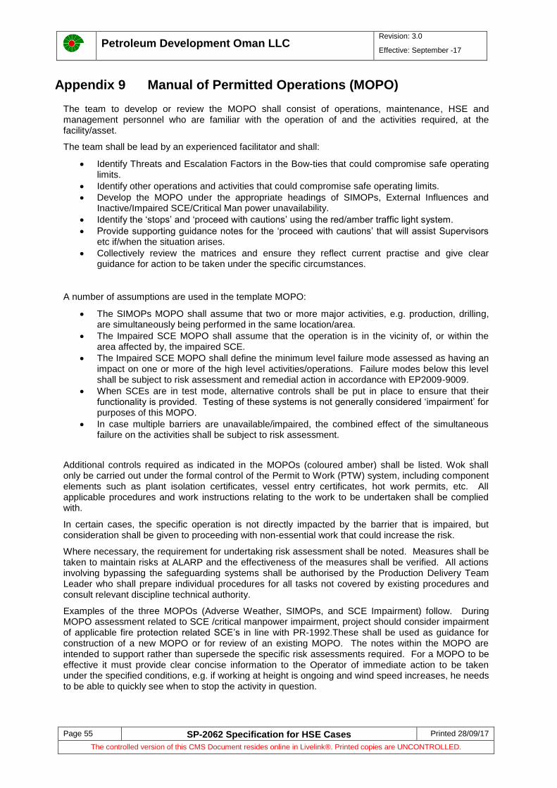
Petroleum Development Oman LLC
Revision: 3.0
Effective: September -17
Page 55 SP-2062 Specification for HSE Cases Printed 28/09/17
The controlled version of this CMS Document resides online in Livelink®. Printed copies are UNCONTROLLED.
Appendix 9 Manual of Permitted Operations (MOPO)
The team to develop or review the MOPO shall consist of operations, maintenance, HSE and management personnel who are familiar with the operation of and the activities required, at the facility/asset.
The team shall be lead by an experienced facilitator and shall:
Identify Threats and Escalation Factors in the Bow-ties that could compromise safe operating limits.
Identify other operations and activities that could compromise safe operating limits.
Develop the MOPO under the appropriate headings of SIMOPs, External Influences and Inactive/Impaired SCE/Critical Man power unavailability.
Identify the ‘stops’ and ‘proceed with cautions’ using the red/amber traffic light system.
Provide supporting guidance notes for the ‘proceed with cautions’ that will assist Supervisors etc if/when the situation arises.
Collectively review the matrices and ensure they reflect current practise and give clear guidance for action to be taken under the specific circumstances.
A number of assumptions are used in the template MOPO:
The SIMOPs MOPO shall assume that two or more major activities, e.g. production, drilling, are simultaneously being performed in the same location/area.
The Impaired SCE MOPO shall assume that the operation is in the vicinity of, or within the area affected by, the impaired SCE.
The Impaired SCE MOPO shall define the minimum level failure mode assessed as having an impact on one or more of the high level activities/operations. Failure modes below this level shall be subject to risk assessment and remedial action in accordance with EP2009-9009.
When SCEs are in test mode, alternative controls shall be put in place to ensure that their functionality is provided. Testing of these systems is not generally considered ‘impairment’ for purposes of this MOPO.
In case multiple barriers are unavailable/impaired, the combined effect of the simultaneous failure on the activities shall be subject to risk assessment.
Additional controls required as indicated in the MOPOs (coloured amber) shall be listed. Wok shall only be carried out under the formal control of the Permit to Work (PTW) system, including component elements such as plant isolation certificates, vessel entry certificates, hot work permits, etc. All applicable procedures and work instructions relating to the work to be undertaken shall be complied with.
In certain cases, the specific operation is not directly impacted by the barrier that is impaired, but consideration shall be given to proceeding with non-essential work that could increase the risk.
Where necessary, the requirement for undertaking risk assessment shall be noted. Measures shall be taken to maintain risks at ALARP and the effectiveness of the measures shall be verified. All actions involving bypassing the safeguarding systems shall be authorised by the Production Delivery Team Leader who shall prepare individual procedures for all tasks not covered by existing procedures and consult relevant discipline technical authority.
Examples of the three MOPOs (Adverse Weather, SIMOPs, and SCE Impairment) follow. During MOPO assessment related to SCE /critical manpower impairment, project should consider impairment of applicable fire protection related SCE’s in line with PR-1992.These shall be used as guidance for construction of a new MOPO or for review of an existing MOPO. The notes within the MOPO are intended to support rather than supersede the specific risk assessments required. For a MOPO to be effective it must provide clear concise information to the Operator of immediate action to be taken under the specified conditions, e.g. if working at height is ongoing and wind speed increases, he needs to be able to quickly see when to stop the activity in question.

Petroleum Development Oman LLC
Revision: 3.0
Effective: September -17
Page 56 SP-2062 Specification for HSE Cases Printed 28/09/17
The controlled version of this CMS Document resides online in Livelink®. Printed copies are UNCONTROLLED.
MOPO – NOTES TO ACCOMPANY THE EXAMPLE MOPOs [EXAMPLE]
NO. REQUIREMENT
1 Operation specific. Subject to well engineering procedures; refer to WECO HSE case.
2 Loading and unloading pigs not permitted in adverse weather conditions.
3 Subject to task-based risk assessment.
4 Subject to appropriate risk assessment and PDO Journey Management Procedures.
5 Continued work subject to heat stress evaluation. Schedule work during cooler part of day. Provide forced ventilation, shaded areas and cold water (not iced). Summer working hours and extended lunch breaks apply.
6 Simultaneous drilling and production operations permitted subject to compliance with minimum separation distances between live wells and flowlines and drilling operations in accordance with HSE Case. Simultaneous drilling and production operations not permitted inside separation distances.
7 Permitted subject to pigging procedures (maximum flow rate for pigging operations).
8 Grit blasting/jet washing not permitted on live systems.
9 Venting permitted outside the sterile area only.
10 Permitted subject to risk assessment with specified controls or mitigation in place.
MOPO – ADVERSE WEATHER CONDITIONS [EXAMPLE]
ACTIVITY/OPERATION
ADVERSE WEATHER CONDITION
WIN
D >
20 K
TS
HE
AV
Y S
HA
MA
L
NIG
HT
TIM
E
WO
RK
ING
HE
AV
Y M
IST
-
SE
VE
RE
LY
R
ED
UC
ED
VIS
IBIL
ITY
HE
AV
Y R
AIN
-
SE
VE
RE
LY
RE
DU
CE
D
VIS
IBIL
ITY
&
WA
DI
FL
OO
DIN
G
LIG
HT
NIN
G
HIG
H A
MB
IEN
T
TE
MP
>50 C
Drilling 1 1 1 1 1 1 1 Well Services 1 1 1 1 1 1 1 Operate Wells/Flowlines Y Y Y Y Y Y Y Operate Pipelines Y Y Y Y Y Y Y Pigging (future) 2 N N 2 2 2 5 QA MPS Operation Y Y Y Y Y Y Y GT operation Y Y Y Y Y Y Y BFW Heater Start-up (Plant Start-up) Y N Y N N N 5 HRSG Start-up (Plant Start-up) Y N Y N N N 5 Steam Distribution Plant Start-up Y N Y N N N 5 Oil & Gas Plant Start-up Y N Y N N N 5 PGC/Plant unit Start-up Y N Y N N N 5 Operate Steam Plant Y Y Y Y Y Y Y Operate Oil & Gas Plant Y Y Y Y Y Y Y APO Operation Y Y Y Y Y Y Y N2/He Leak Testing Y N Y N N N 5 Working Outdoors 3 N Y 3 N N 5 Sampling 3 N Y N N N 5 Radiography Y N Y N N N 5 Vehicle Movement on-plot 3 N Y N N N Y Vehicle Movement off-plot 3 N 4 N N N Y Road Maintenance/ Grading 3 N N N N N 5 Grit Blasting / HP Water Jet 3 N N N N N 5 Lifting/Crane Operations N N N N N N 5 Fork Lift Truck Operations 3 N N N N N 5 High Noise Generating Activities Y N Y N N N 5 Excavation Activities 3 N N N N N 5 Work at Height (outside permanent structures) N N N N N N 5 Working on Tall Structures 3 N N N N N 5 Zone 1 Area Work Y N 3 N N N 5 Zone 2 Area Work Y N Y N N N 5 Breaching Maintenance 3 N Y N N N 5 Non-Breaching Maintenance Y N Y N N N 5 Class A Permit Work Y N Y N N N 5 Class B Permit Work Y N Y N N N 5 HRSG entry Y N Y N N N 5 Confined Space Entry Y N Y N N N 5 Flaring Y Y Y Y Y Y Y Local Venting 3 N Y N N N 5 Draining to open systems Y N Y N N N 5 Chemical unloading 3 N N N N N 5 Chemical Disposal by Vac Truck 3 N N N N N 5 Construction Activities 3 N 3 N N N 5

Petroleum Development Oman LLC
Revision: 3.0
Effective: September -17
Page 57 SP-2062 Specification for HSE Cases Printed 28/09/17
The controlled version of this CMS Document resides online in Livelink®. Printed copies are UNCONTROLLED.
MOPO – SIMOPs [EXAMPLE]
ACTIVITY/OPERATION
DR
ILL
ING
WE
LL
SE
RV
ICE
S
OP
ER
AT
E W
EL
LS
/FL
OW
LIN
ES
OP
ER
AT
E P
IPE
LIN
ES
PIG
GIN
G (
FU
TU
RE
)
QA
MP
S O
PE
RA
TIO
N
GT
OP
ER
AT
ION
BF
W
HE
AT
ER
S
TA
RT
UP
(PL
AN
T S
TA
RT
UP
)
HR
SG
S
TA
RT
UP
(P
LA
NT
ST
AR
TU
P)
ST
EA
M
DIS
TR
IBU
TIO
N
PL
AN
T
ST
AR
T-U
P
OIL
& G
AS
PL
AN
T S
TA
RT
-UP
PG
C/P
LA
NT
UN
IT S
TA
RT
-UP
OP
ER
AT
E S
TE
AM
PL
AN
T
OP
ER
AT
E O
IL &
GA
S P
LA
NT
AP
O O
PE
RA
TIO
N
N2/H
E L
EA
K T
ES
TIN
G
WO
RK
ING
OU
TD
OO
RS
SA
MP
LIN
G
RA
DIO
GR
AP
HY
VE
HIC
LE
MO
VE
ME
NT
ON
-PL
OT
VE
HIC
LE
M
OV
EM
EN
T
OF
F-
PL
OT
RO
AD
M
AIN
TE
NA
NC
E/
GR
AD
ING
GR
IT
BL
AS
TIN
G
/ H
P
WA
TE
R
JE
T
LIF
TIN
G/C
RA
NE
OP
ER
AT
ION
S
FO
RK
L
IFT
T
RU
CK
O
PE
RA
TIO
NS
HIG
H
NO
ISE
G
EN
ER
AT
ING
AC
TIV
ITIE
S
EX
CA
VA
TIO
N A
CT
IVIT
IES
WO
RK
AT
HE
IGH
T
WO
RK
ING
O
N
TA
LL
ST
RU
CT
UR
ES
ZO
NE
1 A
RE
A W
OR
K
ZO
NE
2 A
RE
A W
OR
K
BR
EA
CH
ING
MA
INT
EN
AN
CE
NO
N-B
RE
AC
HIN
G
MA
INT
EN
AN
CE
CL
AS
S A
PE
RM
IT W
OR
K
CL
AS
S B
PE
RM
IT W
OR
K
HR
SG
EN
TR
Y
CO
NF
INE
D S
PA
CE
EN
TR
Y
FL
AR
ING
LO
CA
L V
EN
TIN
G
DR
AIN
ING
TO
OP
EN
SY
ST
EM
S
CH
EM
ICA
L U
NL
OA
DIN
G
CH
EM
ICA
L D
ISP
OS
AL
B
Y V
AC
TR
UC
K
CO
NS
TR
UC
TIO
N A
CT
IVIT
IES
Drilling
Well Services 6
Operate Wells/Flowlines 6 6
Operate Pipelines Y Y Y
Pigging (future) Y Y Y 7
QA MPS Operation Y Y Y Y Y
GT operation Y Y Y Y Y Y
BFW Heater Startup (plant startup)
Y Y Y Y Y Y Y
HRSG Startup (plant startup)
Y Y Y Y Y Y Y Y
Steam Distribution Plant start-up
Y Y Y Y Y Y Y Y Y
Oil & Gas Plant start-up Y Y Y Y Y Y Y Y Y Y
PGC/Plant unit Startup Y Y Y Y Y Y Y Y Y Y Y
Operate Steam Plant Y Y Y Y Y Y Y Y Y Y Y Y
Operate Oil & Gas Plant Y Y Y Y Y Y Y Y Y Y Y Y Y
APO Operation Y Y Y Y Y Y Y Y Y Y Y Y Y Y
N2/He Leak Testing Y Y Y N N Y Y N N N N N N N N
Working Outdoors Y Y Y Y Y Y Y Y Y Y Y Y Y Y Y N
Sampling Y Y Y Y Y Y Y Y Y Y Y Y Y Y Y N Y
Radiography Y Y Y Y Y Y Y N N N N N Y Y Y N N N
Vehicle Movement on-plot Y Y Y Y Y Y Y Y Y Y Y Y Y Y Y N Y N N
Vehicle Movement off-plot Y Y Y Y Y Y Y Y Y Y Y Y Y Y Y Y Y N Y Y
Road Maintenance/ Grading Y Y Y Y Y Y Y Y Y Y Y Y Y Y Y Y Y Y Y Y Y
Grit Blasting / HP Water Jet Y Y 8 8 8 Y Y N N N N N 8 8 8 N N N N N N Y
Lifting/Crane Operations Y Y N N Y Y Y N N N N N Y Y Y N N N N N N Y N
Fork Lift Truck Operations Y Y Y Y Y Y Y N N N N N Y Y Y N Y Y N Y Y Y N N
High Noise Generating Activities
Y Y Y Y Y Y Y Y Y Y Y Y Y Y Y N Y Y Y Y Y Y Y Y Y
Excavation Activities Y Y Y Y Y Y Y N N N N N Y Y Y N Y Y N Y Y Y N N N Y
Work at Height (outside permanent structures)
Y Y Y Y Y Y Y N N N N N Y Y Y N Y Y N Y Y Y N N Y Y Y
Working on Tall Structures Y Y Y Y Y Y Y N N N N N Y Y Y N Y Y N Y Y Y N N Y Y Y Y
Zone 1 Area Work Y Y 3 3 3 Y Y N N N N N 3 3 3 N Y Y N N N N N N N Y N N N
Zone 2 Area Work Y Y Y Y Y Y Y N N N N N Y Y Y N Y Y N Y Y Y N N Y Y Y Y Y N
Breaching Maintenance Y Y N N N Y Y N N N N N Y Y Y N Y Y N N N N N N N Y N N N N N
Non-Breaching Maintenance
Y Y Y Y Y Y Y N N N N N Y Y Y N Y Y N Y Y Y N N Y Y Y Y Y N Y N
Class A Permit Work Y Y 3 3 3 Y Y N N N N N 3 3 3 N Y 3 N Y Y Y N N Y Y Y Y Y N Y N N
Class B Permit Work Y Y Y Y 3 Y Y N N N N N Y Y Y N Y Y N Y Y Y N N Y Y Y Y Y N Y N Y Y
HRSG entry Y Y Y Y Y Y N N N N N N Y Y Y N Y Y N Y Y Y N N Y N Y Y Y N Y N Y Y Y
Confined Space Entry Y Y Y Y Y Y Y N N N N N Y Y Y N Y Y N Y Y Y N N Y N Y Y Y N Y N Y Y Y Y
Flaring Y Y Y Y Y Y Y Y Y Y Y Y Y Y Y Y Y Y Y Y Y Y Y Y Y Y Y N N N Y Y Y Y Y Y Y
Local Venting Y Y Y Y Y Y Y Y Y Y Y Y Y Y Y N N Y N N N N N N N Y N N N N N N N N N N N 9
Draining to open systems Y Y Y Y Y Y Y Y Y Y Y Y Y Y Y N N Y N N N N N N N Y N N N N N N N N N N N Y Y
Chemical unloading Y Y Y Y Y Y Y N N N N Y Y Y Y N Y Y N Y Y Y N N Y Y N N N N N N N N N Y N Y N N
Chemical Disposal by Vac Truck
Y Y Y Y Y Y Y N N N N Y Y Y Y N Y Y N Y Y Y N N Y Y N Y Y N N N N N N Y N Y N N N
Construction Activities Y Y Y Y Y Y Y N N N N Y Y Y Y N Y Y N Y Y Y N N Y Y Y Y Y N Y N Y N Y Y Y Y N N N N

Petroleum Development Oman LLC
Revision: 3.0
Effective: September-17
Page 58 SP-2062 Specification for HSE Cases Printed 28/09/17
The controlled version of this CMS Document resides online in Livelink®. Printed copies are UNCONTROLLED.
MOPO – SCE & CRITICAL MANPOWER IMPAIRMENT/UNAVAILABILITY [EXAMPLE]
ACTIVITY/OPERATION
ST
AR
T-U
P
EQ
UIP
ME
NT
/
SY
ST
EM
ST
AR
T-U
P P
LA
NT
OP
ER
AT
E
EQ
UIP
ME
NT
/
SY
ST
EM
OP
ER
AT
E P
LA
NT
OP
ER
AT
E F
AC
ILT
Y
LIF
TIN
G A
ND
HO
IST
ING
OV
ER
HC
EQ
UIP
ME
NT
GE
NE
RA
L
AC
TIV
ITIE
S
(MA
INT
EN
AN
CE
, IN
SP
EC
TIO
N,
PA
INT
ING
, C
OL
D W
OR
K)
PR
ES
SU
RE
/LE
AK
TE
ST
ING
BR
EA
KIN
G H
C-C
ON
TA
INM
EN
T
(SA
MP
LIN
G,V
EN
TIN
G,D
RA
ININ
G)
HO
T W
OR
K
RO
AD
T
RA
NS
PO
RT
, R
OA
D
TA
NK
ER
S,
LO
AD
ING
/
UN
LO
AD
ING
CO
NF
INE
D
SA
PC
E
EN
TR
Y
(IN
CL
UD
ING
HR
SG
)
IMPAIRED/UNAVAILABLE SCE
SCE GROUP SCE FAILURE MODE
SI002 Civil Structures / Structural Support
Observed or detected structural defect resulting in increased risk of MAH
N 10 N 10 10 10 10 10 10 10 10 10
SI003 Heavy lift cranes and mechanical handling
Observed or detected structural/mechanical defect resulting in increased risk of MAH due to dropped load
Y Y Y Y Y N Y Y Y Y Y Y
PC001 - PC006 Process Containment
Uncontrolled release of process fluids resulting in increased risk of MAH
N N N 10 10 N N N N N N N
PC007 Relief System
Unavailability of relief at design flow rate resulting in increased risk of MAH due to overpressure
N 10 N 10 Y 10 10 10 10 10 10 10
PC008 Operational Well Containment
Uncontrolled release of well fluid resulting in increased risk of MAH
N Y N Y Y 10 10 10 10 10 10 10
PC009 Fired Heaters (Burner Management System)
Unavailability of BMS/IPS resulting in increased risk of MAH
N Y N Y Y Y Y Y Y Y Y Y
IC003 Certified Electrical Equipment
Certified electrical equipment fails to meet PS requirement resulting in increased risk of ignition
N 10 N 10 Y Y Y Y 10 Y 10 Y
IC005 Earth Bonding
Earth bonding fails to meet PS requirement resulting in increased risk of ignition
N Y 10 Y Y Y Y Y 10 Y N Y
IC006 Fuel Gas Purge
Inability to provide required fuel gas purge flow to flare header resulting in air ingress to flare
N N N 10 Y Y Y Y Y Y Y Y
IC007 Gas Blanket System - Total loss
Total loss of gas blanket system resulting in increased risk of ignition
N N N N Y Y Y Y Y 10 Y Y
IC007 Gas Blanket System - Loss to individual equipment
Inability to provide required gas blanket flow individual equipment resulting in increased risk of ignition
N 10 N 10 Y Y Y Y Y 10 Y Y
IC009 Flare Ignition Control System
Loss of primary & secondary flare ignition systems resulting in flare out
N N 10 10 10 10 10 10 10 10 10 10
DS001 Fire and Gas - Total loss
Total loss of F&G detection system
N N N N 10 10 10 10 N N 10 10

Petroleum Development Oman LLC
Revision: 3.0
Effective: September-17
Page 59 SP-2062 Specification for HSE Cases Printed 28/09/17
The controlled version of this CMS Document resides online in Livelink®. Printed copies are UNCONTROLLED.
ACTIVITY/OPERATION
ST
AR
T-U
P
EQ
UIP
ME
NT
/
SY
ST
EM
ST
AR
T-U
P P
LA
NT
OP
ER
AT
E
EQ
UIP
ME
NT
/
SY
ST
EM
OP
ER
AT
E P
LA
NT
OP
ER
AT
E F
AC
ILT
Y
LIF
TIN
G A
ND
HO
IST
ING
OV
ER
HC
EQ
UIP
ME
NT
GE
NE
RA
L
AC
TIV
ITIE
S
(MA
INT
EN
AN
CE
, IN
SP
EC
TIO
N,
PA
INT
ING
, C
OL
D W
OR
K)
PR
ES
SU
RE
/LE
AK
TE
ST
ING
BR
EA
KIN
G H
C-C
ON
TA
INM
EN
T
(SA
MP
LIN
G,V
EN
TIN
G,D
RA
ININ
G)
HO
T W
OR
K
RO
AD
T
RA
NS
PO
RT
, R
OA
D
TA
NK
ER
S,
LO
AD
ING
/
UN
LO
AD
ING
CO
NF
INE
D
SA
PC
E
EN
TR
Y
(IN
CL
UD
ING
HR
SG
)
DS001 Fire and Gas - Local or partial loss
Loss of F&G detection end element resulting in impaired local functionality e.g. 2ooN in voted system & 1ooN in non-voted systems
N 10 10 10 Y 10 10 10 10 10 10 10
DS002 Security Systems
Loss of access control to facilities
10 Y 10 Y Y Y Y Y Y Y Y Y
PS013 Chemical Injection System
Inability to provide required chemical injection flow
10 Y 10 Y Y Y Y Y Y Y Y Y
SD001 ESD System - Total loss
Total loss of ESD system N N N N N 10 10 10 10 10 10 10
SD001 ESD System - Local or partial loss
Local or partial loss of ESD system
N 10 10 10 10 10 10 10 10 10 10 10
SD002 Depressurisation System - Total loss
Total loss of EDP system N N N N N 10 10 10 10 10 10 10
SD002 Depressurisation System - Local or partial loss
Local or partial loss of EDP system
N 10 N 10 10 10 10 10 10 10 10 10
SD004 Operational Well Isolation
Inability to isolate steam injection well or annulus resulting in potential back flow of HC
N Y N Y Y 10 10 10 10 10 10 10
SD006 Process ESDV
Inability of ESD end element valve to adequately isolate processes resulting in potential escalation of MAH
N 10 10 10 10 10 10 10 10 10 10 10
ER001 Temp Refuge/ Muster Areas
Primary muster area impaired
10 10 10 10 10 10 10 10 10 10 10 10
ER002 Escape/ Evacuation Routes
Escape/ evacuation routes impaired
10 10 10 10 10 10 10 10 10 10 10 10
ER003 Emergency/ Escape Lighting
Emergency/ escape Lighting impaired
10 10 10 10 10 10 10 10 10 10 10 10
ER004 Communication Systems - Loss of GA
Loss of GA communication system
N N 10 10 10 10 10 10 10 10 10 10
ER004 Communication Systems - Loss of ER communications
Loss of ER communication system including radios and landlines
N N 10 10 10 10 10 10 10 10 10 10
ER005 Uninterrupted Power Supply (UPS)
Inability to provide emergency power supply to essential systems
N N 10 10 10 Y Y Y Y Y Y Y

Petroleum Development Oman LLC
Revision: 3.0
Effective: September-17
Page 60 SP-2062 Specification for HSE Cases Printed 28/09/17
The controlled version of this CMS Document resides online in Livelink®. Printed copies are UNCONTROLLED.
ACTIVITY/OPERATION
ST
AR
T-U
P
EQ
UIP
ME
NT
/
SY
ST
EM
ST
AR
T-U
P P
LA
NT
OP
ER
AT
E
EQ
UIP
ME
NT
/
SY
ST
EM
OP
ER
AT
E P
LA
NT
OP
ER
AT
E F
AC
ILT
Y
LIF
TIN
G A
ND
HO
IST
ING
OV
ER
HC
EQ
UIP
ME
NT
GE
NE
RA
L
AC
TIV
ITIE
S
(MA
INT
EN
AN
CE
, IN
SP
EC
TIO
N,
PA
INT
ING
, C
OL
D W
OR
K)
PR
ES
SU
RE
/LE
AK
TE
ST
ING
BR
EA
KIN
G H
C-C
ON
TA
INM
EN
T
(SA
MP
LIN
G,V
EN
TIN
G,D
RA
ININ
G)
HO
T W
OR
K
RO
AD
T
RA
NS
PO
RT
, R
OA
D
TA
NK
ER
S,
LO
AD
ING
/
UN
LO
AD
ING
CO
NF
INE
D
SA
PC
E
EN
TR
Y
(IN
CL
UD
ING
HR
SG
)
ER010 Drains System
Inability to provide secondary containment for HC/chemicals spills resulting in potential escalation of MAH
N 10 10 10 Y Y Y Y Y Y 10 Y
LS001 Personal Survival Equipment - Personal monitors
Personal H2S monitors below minimum level or faulty
N N 10 10 10 N N N N N N N
LS001 Personal Survival Equipment - Escape sets
Portable BA Sets below minimum level or faulty (Escape Sets)
N N 10 10 10 N N N N N N N
LS001 Personal Survival Equipment - Rescue BA sets
Portable BA Sets below minimum level (SCBA & Rescue Sets)
N N 10 10 10 N N N N N N N
LS001 Personal Survival Equipment - Chemical PPE
Insufficient number or inadequate type of Chemical PPE available
10 Y 10 Y Y Y Y Y Y Y N Y
LS001 Personal Survival Equipment - Safety showers/eye wash stations
Safety showers/eye wash stations not available or inoperable
10 Y 10 Y Y Y Y Y Y Y N Y
CRITICAL MANPOWER
UNAVAILABILITY[EXAMPLE]
HSE Critical Position
Competent persons not available to fill HSE Critical Position
N N 10 10 10 N N N N N N N
ER - Team Members
Competent persons not available to fill ER team member position
N N 10 10 10 N N N N N N N
ER - QA Fire Brigade
QA fire brigade not available for extended period
10 10 Y Y Y 10 10 10 10 10 10 10
ER - First Aider Insufficient number of first aiders available on-site
10 10 Y Y Y 10 10 10 10 10 10 10
LECC Competent persons not available to fill LECC positions or LECC not available
N N 10 10 10 N N N N N N N

Petroleum Development Oman LLC
Revision: 3.0
Effective: September-17
Page 61 SP-2062 Specification for HSE Cases Printed 28/09/17
The controlled version of this CMS Document resides online in Livelink®. Printed copies are UNCONTROLLED.
Appendix 10 User comment form
SP-2062 – Specification for HSE Cases
Any user who identifies an inaccuracy, error or ambiguity is requested to notify the custodian so that appropriate action can be taken. The user is requested to return this page fully completed, indicating precisely the amendment(s) recommended.
Name:
Ref Indicator Date:
Page Ref: Brief Description of Change Required and Reasons


![PETROLEUM DEVELOPMENT OMAN (PDO) [Elmech] Development Oman - PDO [Elmec… · Petroleum Development Oman L.L.C. ... Postal Address : P.O.BOX 505- PC 114- SULTANATE OF OMAN Is registered](https://img.dokumen.tips/doc/110x75/5ac633c57f8b9a5c558dcb76/petroleum-development-oman-pdo-elmech-development-oman-pdo-elmecpetroleum.jpg)