Embed Size (px)
Citation preview
Alexandria Engineering Journal (2016) 55, 2729–2740
HO ST E D BY
Alexandria University
Alexandria Engineering Journal
www.elsevier.com/locate/aejwww.sciencedirect.com
ORIGINAL ARTICLE
Performance of R.C. slabs with lap splices using
headed bars
* Corresponding author.
E-mail address: [email protected] (A.M. Tarabia).1 Former graduate student.
Peer review under responsibility of Faculty of Engineering, Alexandria
University.
http://dx.doi.org/10.1016/j.aej.2016.05.0181110-0168 � 2016 Faculty of Engineering, Alexandria University. Production and hosting by Elsevier B.V.This is an open access article under the CC BY-NC-ND license (http://creativecommons.org/licenses/by-nc-nd/4.0/).
Ahmed M. Tarabia *, Zaki I. Mahmoud, Mohie S. Shoukry, Amhmed A. Abudina 1
Department of Structural Engineering, Alexandria University, Alexandria, Egypt
Received 1 May 2016; revised 15 May 2016; accepted 17 May 2016
Available online 6 June 2016
KEYWORDS
Concrete slab;
Headed bars;
Lap splice;
Ductility
Abstract This paper presents an experimental investigation on the behavior and strength of
reinforced concrete slabs with lap splice of tension reinforcement using headed bars. Nine simply
supported reinforced concrete one-way slabs were tested to study the effect of lap splices length,
confinement at the splice zone, debonding of bars in the splice zone, and applying repeated gradu-
ally increasing cyclic loading. It was concluded that implementation of lap splice length as stated by
ACI 318-14 for headed bars, but without adding confinement in the splice zone, and using cut-off
ratio equal to 100%, led to brittle failure of the slab and the ductility was reduced. When the tested
slabs were provided with confinement in the splice zone, the strength of slabs was improved and
ductility of these slabs was remarkably increased. Additionally, the integrity of the lap joint was
preserved when subjected to repeated gradually increasing cyclic loading.� 2016 Faculty of Engineering, Alexandria University. Production and hosting by Elsevier B.V. This is an
open access article under the CC BY-NC-ND license (http://creativecommons.org/licenses/by-nc-nd/4.0/).
1. Introduction
The use of bar splices in reinforced concrete members is inevi-
table in many cases because of the limited available length ofthe steel bars and the existence of construction joints. Steelreinforcement can be spliced by several means such as weld-
ing, mechanical couplers or by achieving overlap splices witha minimum length specified by design codes. Bars with headsat their ends are a recent shape of steel reinforcement that are
not commercially available in Egypt till now. The use ofheaded bars shortens the lap splice length when comparedwith straight or hooked bars because of the mechanism of
the load transfer in this case. For lap splice joints usingheaded bars, the force in the bar is transmitted to surrounding
concrete by bearing at the head and bond stresses along thebar surface area in the splice zone. The use of headed barsin lap splice joints is promising because they can enhance
the structural performance including anchorage strength andductility. Also, they can save bar length and reduce congestionof steel reinforcement.
There is no provision in the Egyptian code ECP 203-2007
[1], Eurocode 2-2004 [2], and BS 8110-1997 [3] for the splicerequirements of this type of bars with heads. However, ACI318-14 [4] and Canadian Standards CSA A23.3-04 [5] have
provided some specifications for using headed bars.According to ACI 318-14 [4], the minimum tension
development length for headed deformed bars, ldt, shall be
calculated by Eq. (1) as follows:
2730 A.M. Tarabia et al.
ldt ¼0:19Wefyffiffiffiffi
f 0c
p" #
db P Max of ð8 db; 150 mmÞ ð1Þ
where fc0 is concrete compressive cylinder strength, fy is the
yield strength of reinforcement, We is a modification factor
to account for the coated reinforcement and shall be takenas 1.0 for uncoated bars, and db is the bar diameter. Also,the ACI code, permits to use heads to develop deformed barsin tension depending on fulfilling several conditions concern-
ing bottom and side concrete cover, spacing between bars,yield strength of bars, the area of the head (not to be less thanfour times the nominal bar area) and the nominal diameter of
the bar.Canadian code CSA A23.3-04, allows to use headed bars if
the head area is not less than ten times the bar area and they
shall be deemed capable of developing the tensile strength ofthe headed bar if some conditions concerning strength of con-crete as well as yield stress of steel are existing.
Several researchers [6–8] investigated the use of headed bars
for reinforcing concrete structural members. They concludedthat the anchorage capacity of headed bars can be enhancedby the increase of side concrete cover, and that using confining
reinforcement in the head zone improved the behavior of thesemembers.
Thompson et al. [9] tested 27 slab specimens with lap splices
in the mid-span to study the anchorage of headed barsarranged in one row. The studied parameters were the lengthof lap joint, the shape and dimensions of the head, the spacing
between bars, contact and non-contact lap arrangements, andthe use of confinement in the lap area. These experiments ledto the conclusion that, a minimum lap splice length of 6 dbwas required to properly develop the bearing capacity of the
head. On the other hand, head dimensions and shape had aminor influence on the efficiency of the lap joint. Furthermore,adding transverse confining bars in the same direction of the
plane of the lap splice proved to be the best confinementarrangement for the headed bars with lap splice joints.
Li et al. [10] tested eight reinforced concrete specimens to
study the performance of continuous longitudinal joint detailsfor decked precast prestressed concrete girder bridge systems.Two types of lap splice joints were assessed. 16 mm diameter
epoxy coated Lapped headed bars and lapped welded wirereinforcement were tested to find a better detail of the lap joint.The primary variable was the lap length and the spacing of thereinforcement of the headed bar detail. From the obtained test
results, it was concluded that lapped headed bars can transferforce through the lap joint of the tested specimens. It was rec-ommended that the minimum lap length for the headed bars
detail was 152 mm (about 9.5 bar diameter). This lap lengthwas able to develop the full anchorage strength of the barsand significantly improved ductility. Also, it was observed that
the use of smaller spacing increased the ultimate strength ofthe specimen but reduced its ductility because of the increaseof the area of main steel in the section.
Chun et al. [11] tested 12 beams reinforced with lap-spliced
headed bars to study the behavior of high-strength headedbars. The main studied parameters were lap splice length,bar spacing, and transverse reinforcement details. It was con-
cluded that the existing codes provisions were not conservativefor the lap splice joints of high-strength headed bars, particu-larly, if confinement was not provided. It was observed that in
this case, the bearing at the head could not be fully obtainedbecause of the prying movement of headed bars at the lapjoint. However, when the lap splice joint was confined with
transverse reinforcement throughout the splice length, theend bearing contributions to the force transfer were remark-ably enhanced.
Yassin [12] tested eight reinforced concrete wide beams toinvestigate the behavior and strength of these beams when pro-vided with tension reinforcement using headed bars with lap
splice joints in the mid-span of the beams. The study focusedon studying the effect of lap splices length, spacing of the con-fining vertical stirrups in the splice zone, and the cut-off ratioof the spliced bars on the strength and ductility of the tested
beams. From the results of these experiments, it was concludedthat the use of the lap splice length as specified by ACI 318-08,but without the use of transverse reinforcement in the splice
zone, and with 100% cut-off resulted in a brittle failure. Also,it was reported that when vertical stirrups were provided in thelap zone to confine the lap joint, the strength of beams was
maintained and there was a significant gain in ductility andstrain energy of these beams.
Li et al. [13] recently reported the results of testing precast
concrete panels connection using lap splice of headed bars. Thespecimens were subjected to bending and a combination ofbending and shear loading. The length of lap joint and spacingbetween headed bars were the main studied parameters and no
confinement was used. A strut and tie model was proposed andvalidated for the lap splice of headed bars and the ultimatecapacity of the joint could be reasonably estimated.
In general, most of these studies concentrated on the studyof lap splice of headed bars in beams and confinement wasapplied using stirrups and hoops. This type of confinement is
not practical for slabs and there is a need to try other appro-priate means and details of confinement arrangement for thelap splice joint.
2. Research significance and objectives
As mentioned above in the introduction section, the available
code provisions for the design and detailing of lap splice jointsof headed bars in concrete members are limited. The main goalof this paper was to study the behavior of reinforced concretesimply supported one-way slabs reinforced by lapped-spliced
headed bar provided with different confinement arrangementsin the lap zone. These confinement details were selected to bepractical and easy to implement in slabs. Also, the current
study aimed at obtaining a slab with lap spliced headed barsthat has a strength and ductility not less than those of the sameslab without splice joints. Moreover, the integrity of the lap
splice with two alternative practical confining arrangements,was monitored when subjected to repeated gradually increas-ing cyclic loading.
3. Experimental study
3.1. Preparing headed bars
Headed bars were fabricated using the method suggested byYassin [12]. This suggested bar head detail was obtained by fix-
ing a square steel plate with size (25 � 25 � 10 mm) with a hole

Figure 1 Shape of the prepared headed bar after welding.
Figure 2 Test setup.
Performance of R.C. slabs 2731
in the middle to the main reinforcement bar by passing the bar
through the hole and welding the bar from the two sides of theplate as shown in Fig. 1. Three specimens were tested by directtension to ensure that the welded connection between the bar
and the head did not fail before the ultimate strength. Resultsof these trials are given in Table 1. Failure occurred in the barafter reaching yielding of the bar outside the welded connection.
3.2. Details of the test specimens
Nine simply supported one-way reinforced concrete slabs withdimensions 2400 mm � 1000 mm � 120 mm were tested in the
reinforced concrete laboratory, Alexandria University [14].For all specimens, five 10 mm-diameter (grade 400/600)deformed bars were used as tension bottom reinforcement
and plain bars of 8 mm diameter (grade 280/450) were usedfor the transverse bottom reinforcement. Plain bars of 6 mmdiameter (grade 280/450) were used in the case of confining
the splice zone. The test setup is demonstrated in Fig. 2. Also,the studied variables are given in Table 2 and discussed in thenext sections. Fig. 3 shows reinforcement details for some ofthe tested slabs. It should be noted that Slab AS-1 with no
spliced bars was considered as the reference slab.
3.3. Test groups
The tested slabs were divided into four groups. The main stud-ied variables were as follows.
3.3.1. Group 1: lap splice length
In this study, three different values of lap splice length wereexamined: 45 db without headed bars (Slab AS-2), 15 db withheaded bars (Slab AS-3), and 27 db with headed bars (Slab
AS-7). All slabs in Group 1 were not provided with confine-ment details in the lap splice zone and all bars were spliced(cut-off ratio = 100%).
Table 1 Direct tension test results of headed bars specimens.
Specimen Failure load (kN) Yield stress (fy) (N/mm2) Tensile stren
TR1 54.00 437.12 683.54
TR2 53.50 436.21 677.22
TR3 54.50 439.38 689.87
3.3.2. Group 2: confinement arrangement in the lap zone
Two confinement arrangements were used. The first arrange-ment was of a set of two transverse embedded beams placedat each end of the lap joint perpendicular to the lap splice
direction (Slab AS-5). Each embedded beam consisted of four10 mm longitudinal bars and 6 mm square stirrups(70 mm � 70 mm) spaced at 50 mm apart. The second confine-
ment arrangement was circular spiral 6 mm stirrups with apitch equal to about 50 mm and diameter of 50 mm placedaround each spliced joint (Slab AS-6) in the splice zone and
extended 50 mm behind each head. The lap splice length inGroup 2 was 15 db and the cut-off ratio was 100%. The detailsof the reinforcement of these slabs are also given in Fig. 3.
3.3.3. Group 3: debonding of headed bars in the lap zone
Only one slab was tested to evaluate the efficiency of the headto transfer the load through the lap joint (Slab AS-4) without
the existence of bond between the bar and concrete in lap joint.Bond between concrete and bars in the splice zone was elimi-nated by wrapping a plastic tape around the bars in this zone.
The lap splice length was 15 db and the cut-off ratio was 100%.
3.3.4. Group 4: applying repeated cyclic increasing loading
Two slabs with different stirrups arrangement in the lap splice
zone were tested to evaluate the integrity of the lap joint: Slab(AS-8) with the same details of Slab (AS-5), and Slab (AS-9)similar to Slab (AS-6) in all confinement details. The lap splicelength in Group 4 was 15 db and the cut-off ratio was 100%.
The load was increased in small steps then, this load wasreleased until zero loading. After monitoring cracks, anotherload cycle was applied with an increase in the load step value.
This procedure continued till the failure of the slab.
gth (fu) (N/mm2) (fu/fy) Mode of failure
1.56 Failure occurred in the bar near welding
1.55 Failure occurred in the bar near welding
1.57 Failure occurred in the bar near welding

Table 2 Details of the tested slabs (Cut off ratio in slabs with spliced bars was 100%.).
Slab Group Average concrete
compressive cube
strength, fcu (N/mm2)
Splice length, Lo* Special reinforcement
in the lap zone
Loading Debonding of
lapped bars
AS-1 Reference slab 34.7 No splice – Monotonic Bonded
AS-2 Group 1 36.7 45 db (without
headed bars)
– Monotonic Bonded
AS-3+ Group 1 37.0 15 db – Monotonic Bonded
AS-4+ Group 3 34.9 15 db – Monotonic Debonded
AS-5+ Group 2 35.9 15 db 2 Embedded beams Monotonic Bonded
AS-6+ Group 2 31.7 15 db Spiral stirrups Monotonic Bonded
AS-7+ Group 1 42.1 27 db – Monotonic Bonded
AS-8+ Group 4 30.7 15 db 2 Embedded beams Repeated cyclic loading Bonded
AS-9+ Group 4 31.0 15 db Spiral stirrups Repeated cyclic loading Bonded
* db: bar diameter.+ Slabs with headed bars.
2732 A.M. Tarabia et al.
3.4. Test setup and measurements
The details of the setup of the experiment and loading systemare shown in Fig. 2. The load was applied using a hydraulicjack of 200 kN capacity and the load value was monitored
using a calibrated load cell. A stiff spreader beam was usedto transfer the vertical load to the tested slab at two transverselines 800 mm apart. Three Linear Variable Displacement
Transducers (LVDTs) of 0.01 mm accuracy were utilized to
a- Slab AS-7 (Group 1; Lap
b- Slab AS-6 (Group 2; Confi
c- Slab AS-5 (Group 2; confined us
Figure 3 Reinforcement detai
measure vertical deformations at the center of the slabs andunder the positions of the two applied line loads. For each
slab, two electrical strain gauges of 10 mm length were usedto measure the strain of the bottom steel reinforcement. Straingauges were fixed at the end (near the head of the bar if exist-
ing) and at the start of the splice joint for all slabs. The verticalload was applied in 2.5 kN increments in a low rate. Allmeasurements of loads, deflections and strains were recorded
automatically using data acquisition system.
splice length = 27 db).
ned with spiral stirrups).
ing two embedded beams).
ls of some tested specimens.

Table 3 Main test results.
Slab Group Ultimate load,
Pu (kN)
Deflection at ultimate
load, Du (mm)
Calculated strain energy at
ultimate load (kN m)
Strain Energy at
ultimate load (%)
of reference specimen
AS-1 Reference slab 55.0 38.25 1.748 100%
AS-2 Group 1 55.0 30.91 1.423 81%
AS-3 Group 1 42.5 23.05 0.696 40%
AS-4 Group 3 40.0 13.48 0.412 24%
AS-5 Group 2 62.5 138.56 7.229 414%
AS-6 Group 2 65.0 92.0 4.956 284%
AS-7 Group 1 60.0 83.06 4.255 243%
AS-8 Group 4 60.0 121.45 7.394 423%
AS-9 Group 4 68.0 144.19 8.173 468%
Performance of R.C. slabs 2733
4. Test results and discussion
For each slab, ultimate loads, deflection at failure and the area
under the load–deflection curve for each tested slab (strainenergy), are presented in Table 3. Figs. 4–10 show cracks atfailure of some of the tested slabs. It should be noted thatthe load values shown on cracks in these figures are given in
tons.
4.1. Test results and general behavior of the tested slabs
All slabs in Group 1 were with no confinement arrangement inthe lap zone and 100% cut-off ratio. For slab AS-1 (referenceslab), flexural cracks appeared between the two line loads in
the constant bending moment zone at a load of 30.0 kN. Withthe load increase, flexural cracks propagated to the compres-sion zone and became wider. Bottom main steel yielded at a
load of 50.0 kN. Flexural failure of the slab took place at aload of 55.0 kN. For slab AS-2 with lap splice length equalto 45 db and without headed bars, flexural cracks appearedat the constant moment zone at a load of 25.0 kN. With the
load increase, flexural cracks propagated to the top of the slab,and cracks became wider. Yielding of bottom longitudinal ten-sion steel occurred at a load of 52.5 kN. Failure of the slab
occurred by crushing of concrete in top of the slab at a loadof 55.0 kN. For slab AS-3, with 15 db lap splice length pro-vided with headed bars but without any confinement at the
splice zone, flexural cracks initiated at the constant momentzone at a load of 15.0 kN. As the applied load was increased,flexural cracks formed and appeared along the position of the
Figure 4 Brittle fail
heads at each end of the spliced bars at a load of 20 kN. Withload increase, flexural cracks propagated to the compression
zone at the top of the slab and became wider. No yield of steelreinforcement was recorded in the bottom longitudinal steelbars up to failure. Failure of this slab was sudden with the loss
of bond between concrete and steel which resulted in pushingdown the bottom cover. Pullout of bars occurred at a load of42.5 kN and the failure was brittle as shown in Fig. 4. SlabAS-7 with 27 db lap splice length provided with headed bars
without confinement, flexural cracks initiated at the constantmoment zone at a load of 25.0 kN. With the load increase,cracks appeared at the lap-splice zone at a load of 27.5 kN
and started to propagate to the compression zone and thewidth of cracks became wider. Yielding of main steel occurredat a load of 48.0 kN. At a load of 60.0 kN, flexural ductile col-
lapse of the slab took place.In Group 2, all slabs in this group had a lap splice
length = 15 db and 100% cut-off ratio. In slab AS-5, confined
with two transverse embedded beams perpendicular to thesplice zone, first flexural crack appeared at the constantmoment zone outside the edge of the embedded beams, andextended to the head of the spliced bar at a load of 32.5 kN.
With the load increase, cracks initiated outside of the lap zoneat a location close to transverse embedded beams, and thesecracks started to extend toward the compression zone at the
top of the slab. The first crack inside the lap zone initiated nearthe heads and at the bottom of the transverse embedded beamsat a load of 47.5 kN. During applying the load increase, longi-
tudinal cracks formed outside the end of the lap zone. Thistype of cracks did not propagate between transverses embed-ded beams in the lap zone, but cracks propagated and formed
ure of slab AS-3.
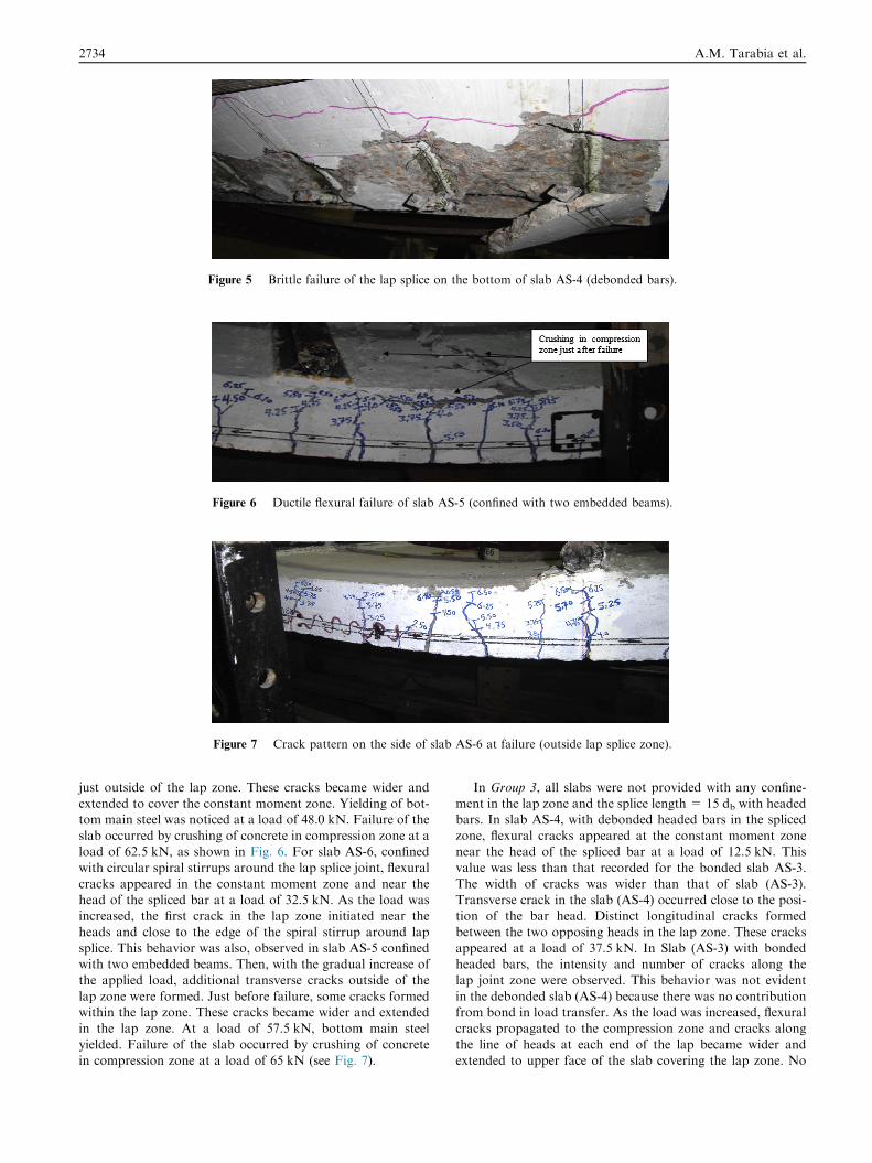
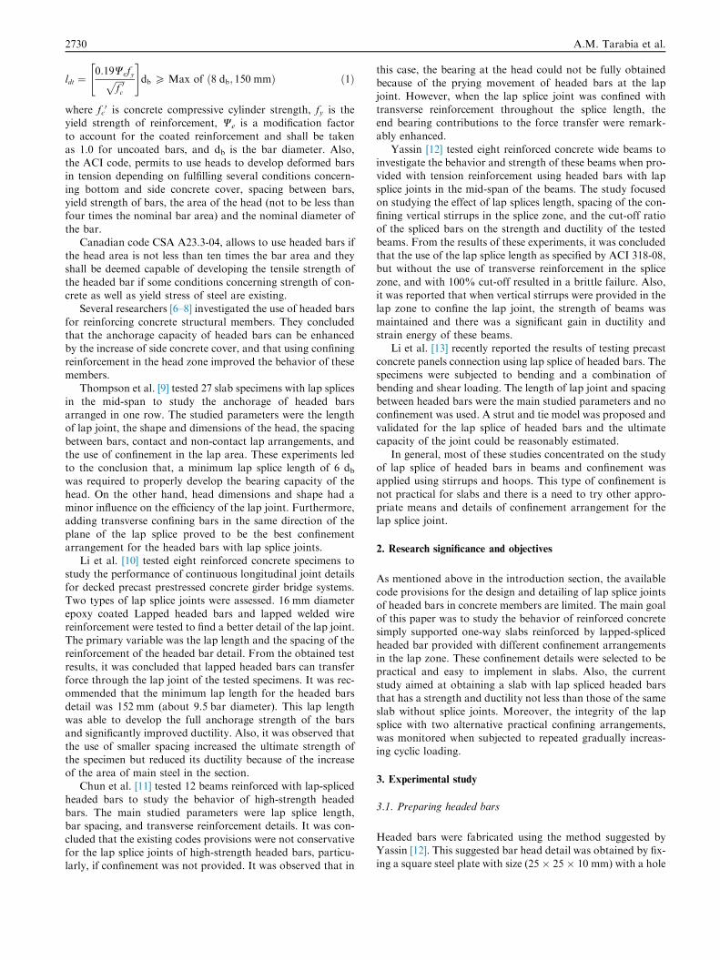
Figure 5 Brittle failure of the lap splice on the bottom of slab AS-4 (debonded bars).
Figure 6 Ductile flexural failure of slab AS-5 (confined with two embedded beams).
Figure 7 Crack pattern on the side of slab AS-6 at failure (outside lap splice zone).
2734 A.M. Tarabia et al.
just outside of the lap zone. These cracks became wider andextended to cover the constant moment zone. Yielding of bot-tom main steel was noticed at a load of 48.0 kN. Failure of the
slab occurred by crushing of concrete in compression zone at aload of 62.5 kN, as shown in Fig. 6. For slab AS-6, confinedwith circular spiral stirrups around the lap splice joint, flexural
cracks appeared in the constant moment zone and near thehead of the spliced bar at a load of 32.5 kN. As the load wasincreased, the first crack in the lap zone initiated near theheads and close to the edge of the spiral stirrup around lap
splice. This behavior was also, observed in slab AS-5 confinedwith two embedded beams. Then, with the gradual increase ofthe applied load, additional transverse cracks outside of the
lap zone were formed. Just before failure, some cracks formedwithin the lap zone. These cracks became wider and extendedin the lap zone. At a load of 57.5 kN, bottom main steel
yielded. Failure of the slab occurred by crushing of concretein compression zone at a load of 65 kN (see Fig. 7).
In Group 3, all slabs were not provided with any confine-ment in the lap zone and the splice length = 15 db with headedbars. In slab AS-4, with debonded headed bars in the spliced
zone, flexural cracks appeared at the constant moment zonenear the head of the spliced bar at a load of 12.5 kN. Thisvalue was less than that recorded for the bonded slab AS-3.
The width of cracks was wider than that of slab (AS-3).Transverse crack in the slab (AS-4) occurred close to the posi-tion of the bar head. Distinct longitudinal cracks formedbetween the two opposing heads in the lap zone. These cracks
appeared at a load of 37.5 kN. In Slab (AS-3) with bondedheaded bars, the intensity and number of cracks along thelap joint zone were observed. This behavior was not evident
in the debonded slab (AS-4) because there was no contributionfrom bond in load transfer. As the load was increased, flexuralcracks propagated to the compression zone and cracks along
the line of heads at each end of the lap became wider andextended to upper face of the slab covering the lap zone. No

Figure 8 Crack pattern on the side of slab AS-7 at failure.
Performance of R.C. slabs 2735
yield of steel reinforcement was recorded in the tension steel upto failure. Failure of the slab was a brittle failure occurred sud-
denly as the heads of bars pushed down the bottom cover andcover separated from the slab at a load of 40 kN as shown inFig. 5. This failure action could be described as a prying actionas the ends of the lapped spliced bars moved outside the bot-
tom of the slab, pushing the bottom concrete cover in lap jointzone.
In Group 4, slabs were subjected to repeated gradually
increasing cyclic loading up to failure. In slab AS-8 confinedwith embedded beams around the bar heads, with the samedetails of slab AS-5, flexural crack appeared in the first cycle
at a load of 20 kN at the constant moment zone, near theend of the stirrups of the embedded beams. With the applyingof loading cycles, the width of cracks parallel to the embedded
Figure 9 Crack pattern on the
Figure 10 Crack pattern on the
beams became wider and flexural cracks propagated to the topcompression zone of the slab. Failure of the slab AS-8,
occurred in the tenth cycle by crushing of concrete in compres-sion zone at load of 60 kN. Fig. 9 shows crack patterns of slabAS-8 at failure. Slab AS-9 was provided with circular spiralstirrups around the lap splice, and had the same reinforcement
details of slab AS-6. In this slab, flexural crack appeared at theconstant moment zone adjacent of the end of circular spiralstirrup in the first cycle at a load of 25 kN. With applying
repeated loading cycles, the cracks formed and initiated out-side of the lap zone close to the end of the spiral stirrups. Also,some cracks started near the head of the bar. In the fifth load-
ing cycle, yielding of the longitudinal headed bars occurred ata load of 50.7 kN (about 75% of the ultimate load; Pu). Thebehavior of this specimen was similar to that of slab AS-8
side of slab AS-8 at failure.
side of slab AS-9 at failure.

0
10
20
30
40
50
60
70
0 20 40 60 80 100
Load
(kN
)
mid-span deflection (mm)
AS-1
AS-2
AS-3
AS-7
Group (1)
AS-3(15db)
Figure 11 Load–deflection curves for Group 1.
0
10
20
30
40
50
60
70
0 500 1000 1500 2000 2500 3000
Load
(kN
)
Strain (A) *10E-6 (mm/mm)
AS-1
AS-2
AS-3
AS-7
yield
Group (1)
εy = 2175 *10E-6
AS-1(Reference)AS-7(27db)AS-2(45db without head)
AS-3(15db)
A
Head of bar
AS-1
Figure 12 Load–steel strain curves for Group 1.
0
10
20
30
40
50
60
70
0 20 40 60 80 100 120 140 160
Load
(kN
)
mid-span deflection (mm)
AS-1AS-3AS-5AS-6
Group (2)
AS-3 ( without confinement)
Figure 13 Load–deflection curves for Group 2.
2736 A.M. Tarabia et al.
which was also provided with embedded beams around the barheads. Failure of slab AS-9 occurred by crushing of concrete incompression zone at load of 68 kN. Crack patterns of slab
AS-9 are demonstrated in Fig. 10 which shows that concreteinside the spiral stirrups zone was not damaged and concretecover did not split off.
4.2. Effect of lap splice length (Group 1)
Fig. 11 shows the applied load–deflection at mid-span relationsfor slabs AS-1, AS-2, AS-3, and AS-7. It can be shown that theload–deflection curve for slab AS-1 (reference slab) and slab
AS-2 (with 45 db lap splice without headed bars) was very

Performance of R.C. slabs 2737
close. Slope of load-defection curve of slab AS-3 was less thanthat of slabs AS-1 and AS-7 after the cracking loads whichindicates that AS-3 is less stiff than other slabs in the Group
1 due to the short unconfined lap splice length. The area underthe load–deflection curve was calculated to measure the totalenergy absorbed by the tested slabs which is called strain
energy or toughness. The strain energy ratios achieved by thetested slabs were 81%, 40%, and 243% for slabs AS-2, AS-3, and AS-7 respectively, of that of Slab AS-1 (reference slab).
The ultimate load values of slabs AS-2, AS-3, and AS-7 of100%, 77%, and 109%, respectively, of that of Slab AS-1 (ref-erence slab). Fig. 12 shows the relationship between measuredsteel strain (at point A) near the head of bar and load for slabs
of group (1). For all slabs in this group except AS-1, straindata indicated that the steel did not yield until failure. It isclear that without using confinement in the lap zone, the
strength and ductility of the reference slab can be maintainedif the lap splice length is 27 db with headed bars, or 45 db withstraight bars with no head. On the other hand, slab AS-3 with
15 db had less strength and ductility.
0
10
20
30
40
50
60
70
0 1000 2000 3
Load
(kN
)
Strain at point A *10E-6
AS-1 (
AS-3 ( without confinement)
εy = 21
Figure 14 Load–steel stra
0
10
20
30
40
50
60
70
0 10 20
Load
(kN
)
mid-span deflectio
AS-3
Figure 15 Load–deflectio
4.3. Effect of using confinement arrangements in the lap zone(Group 2)
Fig. 13 presents load-mid-span deflection relations for slabs ofthis group. The figure indicates that at all load value, the
recorded mid-span deflection of slabs provided with confine-ment at the splice zone was less than that of slab AS-3 pro-vided with no confinement. The strain energies calculated forthe slabs of this group were 81%, 414%, and 284% for slabs
AS-3, AS-5, and AS-6 respectively, of that of slab AS-1 (refer-ence slab). Slabs AS-3, AS-5, and AS-6 failed at an ultimateload equal to 77%, 114%, and 118%, respectively, of that of
slab AS-1 (reference slab). This indicates the enhancement ofductility and energy dissipation of slabs with confined lapsplices. Fig. 14 shows load–strain at point A relation for the
tested slabs in group (2). Strain readings indicated that steeldid not yield until failure of slabs AS-3 (without confinement)and AS-5 (with embedded beams confinement), while for slab
AS-6 (confined with spiral stirrups around lap splice) yield wasrecorded at a load value equal to 62.5 kN just before failure.
000 4000 5000 (mm/mm)
AS-1AS-3AS-5AS-6yield
Group (2)Reference)
A
Head of bar
AS-1
75 *10E-6
in curves for Group 2.
30 40 50
n (mm)
AS-1
AS-3
AS-4
AS-1 (Reference)
(bonded splice joint)
Group (3)
n curves for Group 3.
0
10
20
30
40
50
60
70
0 500 1000 1500 2000 2500
Load
(kN
)
Strain at point A *10E-6 (mm/mm)
AS-1AS-3AS-4yield
Group (3)
AS-1( Reference)
AS-4 (debonded bars)
AS-3 (bonded bars)
A
Head of bar
AS-1
AS-3AS-4
εy = 2175 *10E-6
Figure 16 Load–steel strain curves for Group 3.
0
10
20
30
40
50
60
70
0 20 40 60 80 100 120 140 160
Load
(kN
)
mid-span deflection (mm)
AS-1AS-3AS-5AS-6AS-8AS-9
Group (4)
AS-3 (not confined)AS-8
( embedded beams)
Figure 17 Load–deflection curves for Group 4.
2738 A.M. Tarabia et al.
From these results, for slabs with relatively short lap spliceequal to 15 db, using confinement in the splice zone enabled
the slabs to have a strength slightly higher than the referenceslab and the calculated strain energy was more than twice thatof the reference slab.
4.4. Effect of debonding bars in the lap zone (Group 3)
Fig. 15 displays applied load–deflection at the mid-span rela-
tions for the tested slabs AS-1, AS-3, and AS-4. The figureshows that deflection of slab AS-4 (with debonded bars insplice zone) at failure was about 58% of that of slab AS-3(with bonded bars in splice zone). These results indicated that
elimination of bond between steel reinforcement and concretein the lap splice zone decreased the maximum deflection at fail-ure load and decreased the ductility. The strain energies calcu-
lated for the slabs of this group were 40%, and 24% for slabsAS-3, and AS-4 respectively, of that of slab AS-1 (referenceslab). Slabs AS-3 and AS-4 failed at an ultimate load of
77%, and 73%, respectively, of that of slab AS-1 (referenceslab). Fig. 16 shows the relationship between values of strain(at point A) near the head of bar and load for the tested slabs
in group (3). Main steel bars did not yield till failure of thespliced slabs of this group. Although only one slab was tested
in this group, the head could not develop the force of the barsthrough the lap splice joint and the failure was sudden and
brittle when compared with the bonded slab AS-3 with thesame splice properties.
4.5. Effect of applying repeated gradually increasing loading(Group 4)
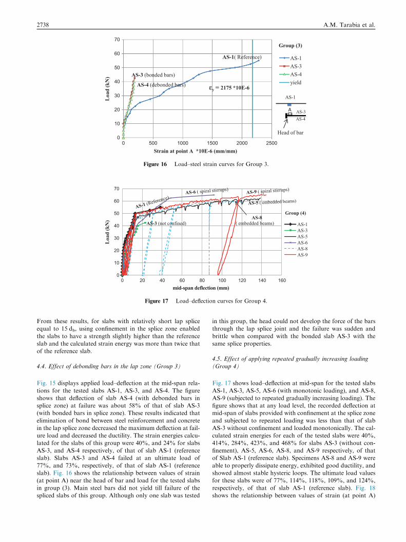
Fig. 17 shows load–deflection at mid-span for the tested slabs
AS-1, AS-3, AS-5, AS-6 (with monotonic loading), and AS-8,AS-9 (subjected to repeated gradually increasing loading). Thefigure shows that at any load level, the recorded deflection atmid-span of slabs provided with confinement at the splice zone
and subjected to repeated loading was less than that of slabAS-3 without confinement and loaded monotonically. The cal-culated strain energies for each of the tested slabs were 40%,
414%, 284%, 423%, and 468% for slabs AS-3 (without con-finement), AS-5, AS-6, AS-8, and AS-9 respectively, of thatof Slab AS-1 (reference slab). Specimens AS-8 and AS-9 were
able to properly dissipate energy, exhibited good ductility, andshowed almost stable hysteric loops. The ultimate load valuesfor these slabs were of 77%, 114%, 118%, 109%, and 124%,
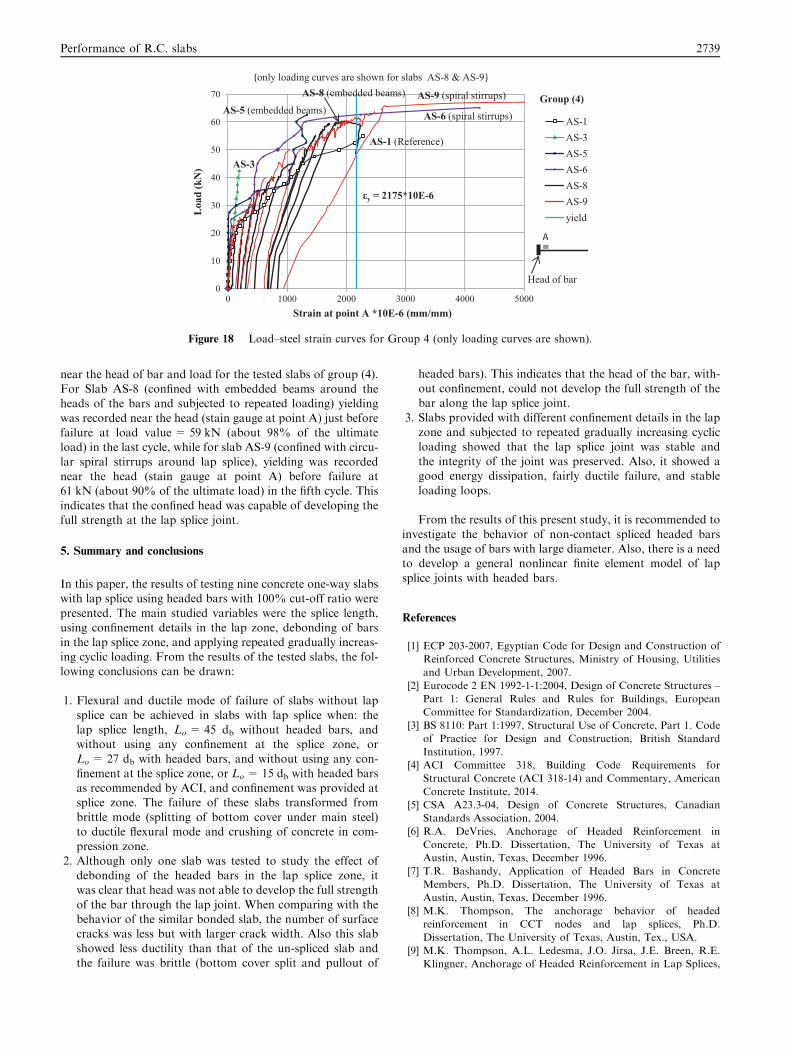
respectively, of that of slab AS-1 (reference slab). Fig. 18shows the relationship between values of strain (at point A)
0
10
20
30
40
50
60
70
0 1000 2000 3000 4000 5000
Load
(kN
)
Strain at point A *10E-6 (mm/mm)
AS-1AS-3AS-5AS-6AS-8AS-9yield
AS-9 (spiral stirrups)
AS-6 (spiral stirrups)
AS-8 (embedded beams)
AS-5 (embedded beams)
AS-3
AS-1 (Reference)
εy = 2175*10E-6
(only loading curves are shown for slabs AS-8 & AS-9 )
Group (4)
A
Head of bar
Figure 18 Load–steel strain curves for Group 4 (only loading curves are shown).
Performance of R.C. slabs 2739
near the head of bar and load for the tested slabs of group (4).For Slab AS-8 (confined with embedded beams around theheads of the bars and subjected to repeated loading) yielding
was recorded near the head (stain gauge at point A) just beforefailure at load value = 59 kN (about 98% of the ultimateload) in the last cycle, while for slab AS-9 (confined with circu-
lar spiral stirrups around lap splice), yielding was recordednear the head (stain gauge at point A) before failure at61 kN (about 90% of the ultimate load) in the fifth cycle. This
indicates that the confined head was capable of developing thefull strength at the lap splice joint.
5. Summary and conclusions
In this paper, the results of testing nine concrete one-way slabswith lap splice using headed bars with 100% cut-off ratio were
presented. The main studied variables were the splice length,using confinement details in the lap zone, debonding of barsin the lap splice zone, and applying repeated gradually increas-ing cyclic loading. From the results of the tested slabs, the fol-
lowing conclusions can be drawn:
1. Flexural and ductile mode of failure of slabs without lap
splice can be achieved in slabs with lap splice when: thelap splice length, Lo = 45 db without headed bars, andwithout using any confinement at the splice zone, or
Lo = 27 db with headed bars, and without using any con-finement at the splice zone, or Lo = 15 db with headed barsas recommended by ACI, and confinement was provided atsplice zone. The failure of these slabs transformed from
brittle mode (splitting of bottom cover under main steel)to ductile flexural mode and crushing of concrete in com-pression zone.
2. Although only one slab was tested to study the effect ofdebonding of the headed bars in the lap splice zone, itwas clear that head was not able to develop the full strength
of the bar through the lap joint. When comparing with thebehavior of the similar bonded slab, the number of surfacecracks was less but with larger crack width. Also this slab
showed less ductility than that of the un-spliced slab andthe failure was brittle (bottom cover split and pullout of
headed bars). This indicates that the head of the bar, with-
out confinement, could not develop the full strength of thebar along the lap splice joint.
3. Slabs provided with different confinement details in the lap
zone and subjected to repeated gradually increasing cyclicloading showed that the lap splice joint was stable andthe integrity of the joint was preserved. Also, it showed agood energy dissipation, fairly ductile failure, and stable
loading loops.
From the results of this present study, it is recommended to
investigate the behavior of non-contact spliced headed barsand the usage of bars with large diameter. Also, there is a needto develop a general nonlinear finite element model of lap
splice joints with headed bars.
References
[1] ECP 203-2007, Egyptian Code for Design and Construction of
Reinforced Concrete Structures, Ministry of Housing, Utilities
and Urban Development, 2007.
[2] Eurocode 2 EN 1992-1-1:2004, Design of Concrete Structures –
Part 1: General Rules and Rules for Buildings, European
Committee for Standardization, December 2004.
[3] BS 8110: Part 1:1997, Structural Use of Concrete, Part 1. Code
of Practice for Design and Construction, British Standard
Institution, 1997.
[4] ACI Committee 318, Building Code Requirements for
Structural Concrete (ACI 318-14) and Commentary, American
Concrete Institute, 2014.
[5] CSA A23.3-04, Design of Concrete Structures, Canadian
Standards Association, 2004.
[6] R.A. DeVries, Anchorage of Headed Reinforcement in
Concrete, Ph.D. Dissertation, The University of Texas at
Austin, Austin, Texas, December 1996.
[7] T.R. Bashandy, Application of Headed Bars in Concrete
Members, Ph.D. Dissertation, The University of Texas at
Austin, Austin, Texas, December 1996.
[8] M.K. Thompson, The anchorage behavior of headed
reinforcement in CCT nodes and lap splices, Ph.D.
Dissertation, The University of Texas, Austin, Tex., USA.
[9] M.K. Thompson, A.L. Ledesma, J.O. Jirsa, J.E. Breen, R.E.
Klingner, Anchorage of Headed Reinforcement in Lap Splices,

2740 A.M. Tarabia et al.
Center for Transportation Research Report 1855-3, Austin,
Texas, May 2002.
[10] L. Li, Z. Ma, M.E. Griffey, R.G. Oesterle, Improved
longitudinal joint details in decked bulb tees for accelerated
bridge construction: concept development, J. Bridge Eng. 15 (3)
(2010) 327–336.
[11] S.C. Chun, J.G. Lee, Anchorage strengths of lap splices
anchored by high-strength headed bars, in: The 8th
International Conference on Fracture Mechanics of Concrete
and Concrete Structures, Toledo, Spain, 2013.
[12] A.M. Yassin, Behavior of reinforced concrete wide beams
provided with lap splices using headed bars, M.Sc. thesis,
Faculty of Engineering, Alexandria University, Alexandria,
Egypt, February 2013.
[13] L. Li, Z. Jiang, Flexural behavior and strut-and-tie model of
joints with headed bar details connecting precast members,
Perspect. Sci. 7 (2016) 253–260.
[14] A.A. Abudiena, Behaviour of reinforced concrete slabs using
headed bars in lap splices, M.Sc. thesis, Faculty of Engineering,
Alexandria University, Alexandria, Egypt, February 2015.