Embed Size (px)
Citation preview

1
Performance Control of Tendon-Driven EndoscopicSurgical Robots With Friction and Hysteresis
Thanh Nho Do,Tegoeh Tjahjowidodo, Michael Wai Shing Lau, and Soo Jay Phee
Abstract—In this study, a new position control scheme forthe tendon-sheath mechanism (TSM) which is used in flexiblemedical devices is presented. TSM is widely used in dexterousrobotic applications because it can flexibly work in limitedspace, in constrained environments, and provides efficient powertransmission from the external actuator to the distal joint.However, nonlinearities from friction and backlash hysteresisbetween the tendon and the sheath pose challenges in achievingprecise position controls of the end effector. Previous studieson the TSM only address the control problem under theassumptions of known tendon-sheath configuration and knownmodel parameters of the backlash hysteresis nonlinearity. Theseapproaches can have adverse impact and limitations on theoverall system performances and practical implementation. Thispaper presents a new approach to model and control the TSM-driven flexible robotic systems. The designed controller doesnot require exact knowledge of nonlinear friction and backlashhysteresis parameters, only their bounds are online estimated.Simulation and experimental validation results show that theproposed control scheme can significantly improve the trackingperformances without the presence of the exact knowlege of themodel parameters and the sheath configuration.
Index Terms—Surgical robot, flexible systems, position control,nonlinearities, dynamic friction, tendon-sheath mechanism.
I. INTRODUCTION
ADVANCES in Minimally Invasive Surgery (MIS) allowsurgeons to perform efficient, high fidelity, and more
complex tasks for surgical treatment while avoiding unex-pected damages such as tissue trauma and reducing recoverytime after the surgery. One of the great developments of MIS isthe Natural Orifice Transluminal Endocopic Surgery (NOTES).In NOTES, procedures are performed through transvaginal,transgastric, or transesophageal approaches with potentiallyscar-free surgery, better cosmetics, and less pain [1], [2]. Inorder to achieve the true potential of NOTES, highly dexterousand cost effective instruments are desired. These desires canbe satisfied with the use of tendon-sheath mechanism (TSM).The tendon can pass through a flexible sheath and it is able towork in very narrow paths and constrained environments withhigh payload and efficient transmission. In most of flexibleendoscopic systems, robotic catheter, and robotic hands, a pairof TSMs is often used to actuate the distal joint while theactuator is externally provided [3], [4], [5], [6],. However,because the nature of the mechanical design for the TSMcreates nonlinear friction and backlash hysteresis, it is achallenging task to acurately model and control the position ofthe distal joint, especially in the absence of model parametersand the sheath configuration. These nonlinearities have alsorestricted the use of the TSM in the development of various
flexible endoscopic devices despite its advantages [7], [8], [9],[10].
Friction is a nature resistance to relative motion between twocontacting bodies. If the position controller is designed withoutconsidering the friction and backlash hysteresis, the trackingerror in the closed-loop system will result in steady-state oroscillations [11], [12], [13]. Many studies have been devotedto the development of position/force transmission and controlfor the TSM. Based on the system dynamics, the tendon-sheathtransmission can be either modelled by an approximationof the backlash hysteresis profile [14], [15] or in terms ofthe lumped-mass model in combination with static frictionmodel like the Coulomb model [16]. It has been known thatthe use of static friction model can result in discontinuousproblem when the system reverses its motion. Hence, Palliet al. [17] used the LuGre model in combination with thelumped-mass parameters to overcome this drawback. However,the model approach is still not able to capture the completenonlinear characteristics of tendon-sheath friction for bothsmall displacement (presliding regime) and large displacement(sliding regime). In addition, the tendon configuration andforce feedback must be known in advance. To fully capture thedynamic properties for both the sliding and presliding regimes,Do et al. [18], [19], [20] first designed novel dynamic frictionmodels for a single TSM. Although the designed models wereable to characterize all the friction phenomena for the TSM,these models require a large number of parameters in theirstructure. Later, Do et al. [21] developed a new dynamicfriction model for a pair of TSMs with fewer parameters inthe designed approach. However, no motion control schemeshave been introduced to compensate the tracking error.
Many attempts on the position control of the TSM have beenstudied in the literature. Agrawal et al. [14] used a smoothbacklash inverse model to enhance the tracking performancesfor the tendon-sheath system. In the applications of roboticcatheter and flexible endoscope, Bardou et al. [22], Kesner etal. [23], and Reilink et al. [24] used an inverse backlash modelto compensate for the phase lags between the output positionand the desired trajectory of the TSM. However, an inversemodel and a discontinuous switching function of velocity wereneeded. Although Do et al. [15], [25], [26] used a directinverse model-based feedforward compensation to overcomethe above limitations, the controller was designed for a fixedtendon-sheath configuration, known backlash hysteresis pa-rameters, and known bounds in advance.
Several work has been introduced to compensate for thetracking error in the presence of nonlinear friction and back-lash hysteresis model by using different nonlinear control
arX
iv:1
702.
0206
3v1
[cs
.RO
] 6
Feb
201
7

2
techniques. Recent studies on the mechanical systems likemagnetic devices or piezoelectric actuators have focused onthe perfect cancellation of nonlinearities using inverse modelsand adaptive algorithms with unknown model parameters anddisturbances. However, little experimental validations havebeen carried out to demonstrate the practical implementationfor the proposed approaches [27], [28], [29]. To fulfil thecomplete picture for the tendon-sheath control, this paperintroduces an adaptive compensation technique for the TSMusing the new dynamic friction model given by [21]. Thedesigned approach takes into account the dynamics of thetendon routing through the sheath regardles of the sheathconfiguration. In addition, the designed laws do not require theknowledge of the friction model and environment parameters;the structure of the controller is designed based on the stan-dard backstepping technique and adaptive updated laws [30],[31] [32], [33], [34], [35]. To validate the proposed modelapproach, an experimental platform is introduced. Simulationand real-time test results confirm that the proposed controllersignificantly improves the position tracking performances forthe TSM.
The rests of this paper are organized as follow: In sectionII, problem formulation for the tendon-sheath system is given.Section III introduces the nonlinear and adaptive controllerdesign. Simulation illustration for the proposed control schemeis shown in section IV. The experimental setup and validationresults are shown in section V. Finally, the discussion andconclusion are drawn by section VI.
II. PROBLEM FORMULATION
A. Dynamic Friction for the TSM
The dynamic friction force F for the TSM can be describedas follows [21]:
F = kxφxi + kζζ + υxi + F0
ζ = ρ(xi − σ|xi||ζ|n−1ζ + (σ − 1)xi|ζ|n)
φ =(e2xi + tanh(xi) tanh(xi))
e2xi + 1
(1)
where xi, xi, xi are the angular position (in radians), veloc-ity, and acceleration at the actuator side, respectively; F is thetotal friction forces in the TSM; kζ is a factor that expressthe ratio of the internal state ζ to the friction force; kx is thestiffness factor that controls seperate curves of the hysteresisloops; ρ > 0, σ > 0.5, n ≥ 1 are coefficients that controlthe shape and size of hysteresis loops for the friction force;tanh(•) is the hyperbolic tangent function which is defined astanh(•) = (e2(•)−1)/(e2(•) +1); υ is the viscous coefficient;and F0 is a offset point of the friction force; the dot at thetop of variables represents the first derivative with respect totime.
Remark 1: It is noted that the variable ζ given by (1) isuniformly bounded for any piecewise continuous signals xi, xi(See [36], [37] for more details). This important property willbe used for the controller design in the next sections.
B. Dynamic Model of the Distal Joint
The dynamic model for the TSM-driven joint with therotational inertias m, damping coefficient c, input torque at thedistal end To, external disturbance torque Td with unknownbound, and environmental torque Te applied to the joint asshown in Fig. 1 can be described as [38]:
my + cy = To − Te − Td (2)
where y is the rotational displacement of the distal joint.
Fig. 1. Torque Transmission for the TSM
Let Tj(j = 1, ..., 4) be tensions at the actuator and the jointsides of each tendons and let ri, ro be radii of the pulleys at theactuator and joint sides. The mass of tendons is usually smalland can be ignored. Then the relation between the proximaltorque Ti = u = (T2 − T1)ri (u is the control input forthe system) and the distal torque To = (T4 − T3)ro can beexpressed as Ti/ri = To/ro + F where F = (T2 − T4) +(T3 − T1) is the total friction forces between the tendons andthe sheaths. The Eq. (2) can be rewritten by:
my + cy = ro(u/ri − F )− Te − Td (3)
We define the system states as x = [x1, x2]T = [y, y]T ; thenthe dynamics of the joint in the tendon-sheath system can besimplified as:
x1 = x2
x2 = (1/m)(ro(u/ri − F )− Te − Td − cx2)
y = x1
(4)
The friction force F is described by (1). Then the variablex2 given by 4 can be rewriten as:
x2 =1
m(ro(u/ri − kxφxi − υxi)− cx2 +D)
=1
m((ro/ri)u+D) + ΘTϕ (5)
where ϕ,D,Θ are expressed with the following forms:ϕ = [φxi, xi, x2]T=[xi(e
2xi + tanh(xi) tanh(xi))/(e2xi +
1), xi, y]T , D = −ro(kζζ + F0) − Te − Td, and Θ =[−rokx/m,−roυ/m,−c/m]T .
The objective of this paper is to design the control input usuch that:
• The output y accurately tracks the desired trajectory yras close as possible.
• The tracking error er = y−yr and estimate variables arebounded.

3
III. CONTROLLER DESIGN
To design the controller u and suitable adaptive laws,some assumptions are needed: (i) The positions y, xi aremeasurable; (ii) the desired trajectory yr, yr, yr are continuousand bounded; (iii) The environmental torque Te and externaldisturbance Td are bounded by unknown bounds. From Re-mark 1 and assumption (iii), the variable D is bounded byan unknown variable D∗ (|D| ≤ D∗) due to ζ, Te, Td arebounded.
To use the backstepping technique [30], [31], the change ofcoordinate transformations is made to the system (4) and (5):
ξ1 = x1 − yr (6)ξ2 = x2 − yr + αv1ξ1 (7)
where αv1 is a positive designed parameter that will bedetermined later.
From (6) and (7), the new coordinates for the system (4)and (5) can be expressed by:
ξ1 = ξ2 − αv1ξ1 (8)
ξ2 =1
m((ro/ri)u+D) + ΘTϕ− yr + αv1ξ1 (9)
Let D∗, m, Θ and D∗ = D∗ − D∗, m = m − m, Θ =Θ − Θ be the estimates and error estimates of D∗,m,Θ,respectively. Define a virtual control input u such that u =mu − D∗ tanh(ξ2/ε) where ε > 0 will be determined later.From (8) and (9), parameter update laws D∗, m, Θ and controlinput u are designed as follow:
u = (ri/ro)(mu− D∗ tanh(ξ2/ε)) (10)
u = yr − αv1ξ1 − ξ1 − αv2ξ2 − ΘTϕ (11)˙Θ = kΘξ2ϕ− σ1Θ (12)˙m = −kmξ2u− σ2m (13)
˙D∗ = kDξ2 tanh(ξ2/ε)− σ3D
∗ (14)
where αv1, αv2, kΘ, km, kD, σi(i = 1, 2, 3) are positive pa-rameters that adjust the designed controller u to force thetracking error er = y − yr approaches desired values.
With (10) to (14), the following theorem holds:Theorem 1: Consider the nonlinear system (8) and (9) with
the designed controller u from (10) to (11) and adaptive laws(12) to (14), the following statements hold:
1) The tracking error er and adaptive laws D∗, m, Θ areglobally uniformly bounded.
2) In the presence of unknown model parameters and theirbounds, the position tracking error converges to a desiredcompact region Ω = |er|
∣∣|er| ≤ 2√%/Ψ.
where Ψ = (σ1/2kΘ)ΘTΘ + 0.2785εD∗/m+ (σ2/2km)m+(σ3/2mkD)(D∗)2; % = min2αv1, 2αv2, σ1, σ2, σ3.
Proof: See appendix A.Remark 2: For practical implementation of the proposed
controller and adaptive laws given by (10) to (14), simulationshave been carried out. Some guidelines are recommended todetermine the designed control parameters:
• The parameters αv1 and αv2 determine the level of theconvergence speed of er. Large values of αv1 and αv2
will lead to faster convergence of the tracking error.However, if these values are too large, it may causechattering in the controller. High values of parameterskΘ, km, kD will improve the parameter adaptation speedand tracking performances. In addition, ε is used toguarantee the smoothness and avoid the discontinuity ofthe controller u given by (10). A small value of ε isdesired. Therefore, we suggest to fix αv1 and αv2 atacceptable large values and ε at a small value and thenincrease the other parameters such as kΘ, km, kD untilthe desired tracking performances are achieved.
• The parameters σ1, σ2, σ3 are used to prevent the estimatevalues of Θ, m, D∗ to be very large. However, largevalues of σ1, σ2, σ3 may suppress the prevention. Hence,small values for σ1, σ2, σ3 are expected.
IV. SIMULATION RESULTS
In this section, simulation studies which illustrate the per-formances of the proposed adaptive controller are presented.Various simulations will be carried out in order to finda good set of controller parameters. The dynamic frictionmodel parameters are chosen based on experimental vali-dation and offline identification from Do et al. [21] wherekx = 0.01083, ρ = 54.658, n = 2.0458, σ = 1.58, kζ =0.14368, υ = 0.02686, F0 = 0.0099. The parameters for thedynamic joint are selected as m = 0.0349, c = 0.0105. Theenvironment is simulated as an eleastic spring Te = key whereke = 0.4185, y is the output position. The disturbance ischosen like Td = 0.2 sin(0.2πt). The designed controller andupdated law parameters are selected basing on the guidelinesgiven by the Remark 2. With this idea, we choose the controlparameters as αv1 = 10, αv2 = 15, kΘ = 0.5, km =0.5, kD = 1, σi = 0.01 (i = 1, 2, 3), ε = 0.05. The pulleyradii are 25mm. The initial condition for updated estimateparameters are chosen such as Θ(0) = [0, 0, 0]T , m(0) =0, D∗(0) = 0. The desired trajectory is selected as yr =0.4 sin(0.4πt).
0 10 20 30 40 50−0.4
−0.2
0
0.2
0.4
Time (s)
Pos
ition
(ra
d)
0 10 20 30 40 50−0.4
−0.2
0
0.2
0.4
Time (s)
Err
or (
rad)
Desired trajectory Output
Fig. 2. Simulation results with the designed adaptive laws:(Upper panel) Timehistory of the desired trajectory yr and the output y; (Lower panel) Trackingerror
On the basis of the chosen parameters, one of the simulationresults for the designed control laws is presented. Fig. 2 shows
4
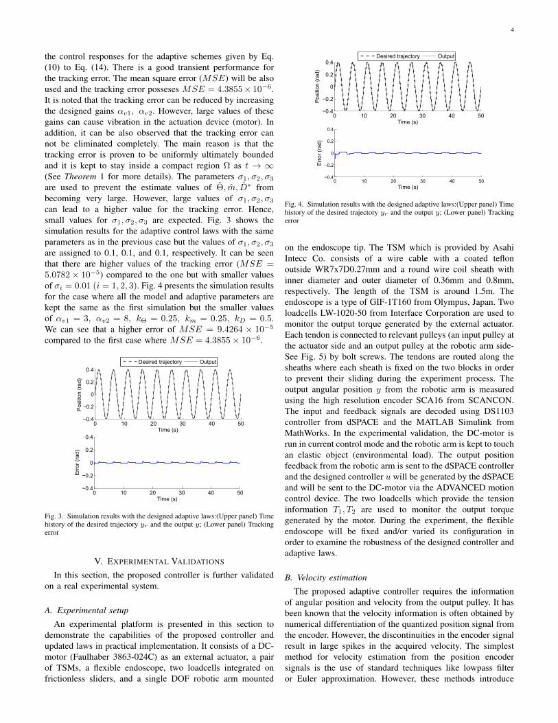
the control responses for the adaptive schemes given by Eq.(10) to Eq. (14). There is a good transient performance forthe tracking error. The mean square error (MSE) will be alsoused and the tracking error posseses MSE = 4.3855× 10⁻⁶.It is noted that the tracking error can be reduced by increasingthe designed gains αv1, αv2. However, large values of thesegains can cause vibration in the actuation device (motor). Inaddition, it can be also observed that the tracking error cannot be eliminated completely. The main reason is that thetracking error is proven to be uniformly ultimately boundedand it is kept to stay inside a compact region Ω as t → ∞(See Theorem 1 for more details). The parameters σ1, σ2, σ3
are used to prevent the estimate values of Θ, m, D∗ frombecoming very large. However, large values of σ1, σ2, σ3
can lead to a higher value for the tracking error. Hence,small values for σ1, σ2, σ3 are expected. Fig. 3 shows thesimulation results for the adaptive control laws with the sameparameters as in the previous case but the values of σ1, σ2, σ3
are assigned to 0.1, 0.1, and 0.1, respectively. It can be seenthat there are higher values of the tracking error (MSE =5.0782× 10⁻⁵) compared to the one but with smaller valuesof σi = 0.01 (i = 1, 2, 3). Fig. 4 presents the simulation resultsfor the case where all the model and adaptive parameters arekept the same as the first simulation but the smaller valuesof αv1 = 3, αv2 = 8, kΘ = 0.25, km = 0.25, kD = 0.5.We can see that a higher error of MSE = 9.4264 × 10⁻⁵
compared to the first case where MSE = 4.3855× 10⁻⁶.
0 10 20 30 40 50−0.4
−0.2
0
0.2
0.4
Time (s)
Pos
ition
(ra
d)
0 10 20 30 40 50−0.4
−0.2
0
0.2
0.4
Time (s)
Err
or (
rad)
Desired trajectory Output
Fig. 3. Simulation results with the designed adaptive laws:(Upper panel) Timehistory of the desired trajectory yr and the output y; (Lower panel) Trackingerror
V. EXPERIMENTAL VALIDATIONS
In this section, the proposed controller is further validatedon a real experimental system.
A. Experimental setup
An experimental platform is presented in this section todemonstrate the capabilities of the proposed controller andupdated laws in practical implementation. It consists of a DC-motor (Faulhaber 3863-024C) as an external actuator, a pairof TSMs, a flexible endoscope, two loadcells integrated onfrictionless sliders, and a single DOF robotic arm mounted
0 10 20 30 40 50−0.4
−0.2
0
0.2
0.4
Time (s)
Pos
ition
(ra
d)
0 10 20 30 40 50−0.4
−0.2
0
0.2
0.4
Time (s)
Err
or (
rad)
Desired trajectory Output
Fig. 4. Simulation results with the designed adaptive laws:(Upper panel) Timehistory of the desired trajectory yr and the output y; (Lower panel) Trackingerror
on the endoscope tip. The TSM which is provided by AsahiIntecc Co. consists of a wire cable with a coated teflonoutside WR7x7D0.27mm and a round wire coil sheath withinner diameter and outer diameter of 0.36mm and 0.8mm,respectively. The length of the TSM is around 1.5m. Theendoscope is a type of GIF-1T160 from Olympus, Japan. Twoloadcells LW-1020-50 from Interface Corporation are used tomonitor the output torque generated by the external actuator.Each tendon is connected to relevant pulleys (an input pulley atthe actuator side and an output pulley at the robotic arm side-See Fig. 5) by bolt screws. The tendons are routed along thesheaths where each sheath is fixed on the two blocks in orderto prevent their sliding during the experiment process. Theoutput angular position y from the robotic arm is measuredusing the high resolution encoder SCA16 from SCANCON.The input and feedback signals are decoded using DS1103controller from dSPACE and the MATLAB Simulink fromMathWorks. In the experimental validation, the DC-motor isrun in current control mode and the robotic arm is kept to touchan elastic object (environmental load). The output positionfeedback from the robotic arm is sent to the dSPACE controllerand the designed controller u will be generated by the dSPACEand will be sent to the DC-motor via the ADVANCED motioncontrol device. The two loadcells which provide the tensioninformation T1, T2 are used to monitor the output torquegenerated by the motor. During the experiment, the flexibleendoscope will be fixed and/or varied its configuration inorder to examine the robustness of the designed controller andadaptive laws.
B. Velocity estimation
The proposed adaptive controller requires the informationof angular position and velocity from the output pulley. It hasbeen known that the velocity information is often obtained bynumerical differentiation of the quantized position signal fromthe encoder. However, the discontinuities in the encoder signalresult in large spikes in the acquired velocity. The simplestmethod for velocity estimation from the position encodersignals is the use of standard techniques like lowpass filteror Euler approximation. However, these methods introduce

5
(a)
(b)
Fig. 5. Experimental setup: (a) Illustrated diagram of the experimentalplatform, (b) Photo
significant delay. There are several methods to provide anaccurate estimation of the velocity from the measured positionof the encoder in the literature [39], [40], [41]. Among all ofthem, a low-noise velocity estimation offers simple approach,high efficiency, and easy to implement for estimating thevelocity to the controller design [42]. In this method, only themeasured position from the encoder is required. The blockdiagram for velocity estimator is presented in Fig. 6.
Fig. 6. Velocity estimator from the measured position of encoder, reproducedfrom [42]
In Fig. 6, xencoder and xestimation are the measured posi-tion from the encoder and the estimated position after usingthe proposed filter, respectively; xestimation is the estimateof velocity from the position encoder; the transfer functionG(s) = s/(τs + 1) where parameter τ is the filter time-constant. The gain K determines the fast part of the speedestimator. The dead-zone is determined basing on the angularresolution of the encoder where the deadband ∆x = π/2nand n is number of cycles per revolution of the encoder.
T is the sampling time for the experimental process. Inthe experiment, the parameter for velocity estimation areT = 0.01, τ = 0.2,K = 20, n = 3600. The experimentalresult for the real differentiation of the measure signal from theencoder and by the proposed velocity estimate is shown in Fig.7. The upper panel of this figure presents relation between thexencoder and xestimation while the lower panel of this figureintroduces the estimation result for the velocity.
−0.4 −0.2 0 0.2 0.4−0.4
−0.2
0
0.2
0.4
Measuredvpositionv(rad)
Est
imat
edvp
ositi
onv(
rad)
0 10 20 30 40 50−4
−2
0
2
4
Timev(s)
Vel
ocity
v(ra
d/s)
DerivativevofvmeasuredvpositionEstimatedvvelocity
Fig. 7. Velocity estimator from the measured position of encoder
C. Experimental validation resultsExperiments have been carried out using the designated
setup given by section V-A. On the basis of the designedcontrol and updated parameters given by section IV, thenonlinear and adaptive controller (10) to (14) can be easilyimplemented in real-time experiments. In order to demonstratethe effectiveness of the proposed control scheme, five trialswill be carried out for the experiments. For illustration, one ofthe trials will be presented only. Fig. 8 shows the experimentalresults of one of the five trials without using any compensationcontrol schemes. The upper panel of this figure introduces thetime history of the desired trajectory yr = 0.3 sin(0.4πt). andthe measured position output y. It can be observed that theoutput y always lags behind the desired trajectory yr witha high error value of mean square error (MSE) of 0.0022rad2. For easier observation and comparison, the tracking errorbetween y and yr is also shown in the lower panel of Fig. 8.
For the case of fixed configuration of the endoscope: Theendoscope is kept at a fixed shape configuration during theexperiment. In this experiment, the nonlinear and adaptivecontroller will drive the measured output y to accurately followthe desired trajectory yr = 0.4 sin(0.4πt). Fig. 9 presentsthe experimental result for this case. It can be observedthat the measured output position y accurately tracks thedesired path yr (see the upper panel of Fig. 9). There is asignificant decrease in the tracking error from a high value ofMSE = 0.0022 rad2 before compensation to a smaller valueof MSE = 2.1977× 10⁻⁴ rad2. This reduction can be easilyseen from the lower panel of Fig. 9. Quantitative comparisonmeasures of the validation are shown in Table I.
For the case of varied configuration of the endoscope: Thepreviously presented validation has not demonstrated the fun-damnetal improvement of the proposed control scheme when

6
0 10 20 30 40 50 60−0.4
−0.2
0
0.2
0.4
Time (s)
Pos
ition
(ra
d)
0 10 20 30 40 50 60−0.4
−0.2
0
0.2
0.4
Time (s)
Err
or (
rad)
Desired trajectory Measured output
Fig. 8. Tracking performance of the system without using any compensationcontrol schemes: (Upper panel) Time history of the desired trajectory yr andthe output y; (Lower panel) Tracking error
0 10 20 30 40 50 60−0.4
−0.2
0
0.2
0.4
Time (s)
Pos
ition
(ra
d)
0 10 20 30 40 50 60−0.4
−0.2
0
0.2
0.4
Time (s)
Err
or (
rad)
Desired trajectory Measured output
Fig. 9. Experimental results for the proposed adaptive controller with fixed theendoscope configuration: (Upper panel) Time history of the desired trajectoryyr and the output y; (Lower panel) Tracking error
the endoscope varies during the experiment. As mentioned inthe first section, the friction force varies with the change ofthe endoscope configuration. In this section, the configurationof the endoscope is randomly varied during the validation.It can be seen that the designed controller is able to dealwith the disturbance due to the change of the endoscopeconfiguration. The upper panel of Fig. 10 shows that thereis a good tracking performance between yr and y when thenonlinear controller is applied to the system. A significantdecrease of the tracking error from MSE = 0.0022 rad2 toa smaller value of MSE = 2.7876 × 10⁻⁴ rad2. There is asmall change in the tracking error compared to the case whereno change of the endoscope configuration is carried out. Thequantitative measures in terms of MSE are also introducedin the Table I.
VI. DISCUSSIONS AND CONCLUSION
An adaptive controller for a friction model in the TSMhas been developed. Simulation and experimental tests havebeen carried out to show the better performances of thedesigned adaptive scheme. The proposed approach is able todeal with nonlinearities in the presence of unknown frictionmodel parameters and unknown environments. Unlike current
TABLE IQUANTITATIVE MEASURES OF THE ERROR USING THE DESIGNED
CONTROLLER
Trials MSE (Fixed configuration) MSE (Varied configuration)
1 2.1977× 10⁻⁴ 2.7876× 10⁻⁴
2 1.1921× 10⁻⁴ 2.1214× 10⁻⁴
3 2.5114× 10⁻⁴ 2.8328× 10⁻⁴
4 2.3282× 10⁻⁴ 2.9655× 10⁻⁴
5 1.6461× 10⁻⁴ 3.3967× 10⁻⁴
0 1 2 3 4 5 6−0.4
−0.2
0
0.2
0.4
Time (s)
Pos
ition
(ra
d)
0 1 2 3 4 5 6−0.4
−0.2
0
0.2
0.4
Time (s)
Err
or (
rad)
Desired trajectory Measured output
Fig. 10. Experimental results for the proposed adaptive controller withvariation of the endoscope configuration: (Upper panel) Time history of thedesired trajectory yr and the output y; (Lower panel) Tracking error
approaches on the TSM control in the literature, our proposedscheme has effectively reduced the tracking error and it isproven to be robust. Comparisons between the experimentalresults and the simulation show good performances. No exactknowledge of friction and backlash hysteresis parameters arerequired. This means that the proposed approach has potentialbenefits to real implementations for the TSM. Although theproposed model works well for both simulation and real-timeexperiment, traditional encoders have been used to get theposition feedback from the distal end. It has been knownthat some applications can utilize advanced techniques suchas 3D ultrasound probe or image-based methods to obtainthe position output feedback and reduce the bulky space forthe systems [22], [23], [24]. Hence, these non-conventionaltechniques can be applied to the system in order to fulfill theneeds for the real applications. In addition, there still exists alittle vibration in the experimental results. This vibration maycome from some unexpected unknown disturbances and thefriction in the DC-motor during the experiment. The sensornoise may also be a part of the issue. Therefore, in the futurework, we will take into account the dynamic model for themotor under the presence of unknown friction and backlashhysteresis. New nonlinear and adaptive control schemes will bedeveloped to accurately estimate and identify all the unknownmodels and parameters. Higher efficiency for the velocityestimation from the measured encoder will be also developed.In-vivo on live animal and human will be also carried out tohigher degrees of freedom of the slave manipulator for furthervalidations.

7
ACKNOWLEDGMENT
The authors would like to thank Mr. Dung Van Than for hishelp to calibrate devices and setup experimental process.
APPENDIX APROOF OF THEOREM 1
Define a Lyapunov function candidate V as follows:
V =ξ21
2+ξ22
2+
ΘT Θ
2kΘ+
m2
2mkm+
(D∗)2
2mkD(15)
The derivative of V along (8) to (14) can be obtained as:
V = ξ1ξ1 + ξ2ξ2 −ΘT ˙
Θ
kΘ− m ˙m
mkm− D∗ ˙
D∗
mkD= ξ1(ξ2 − αv1ξ1)
+ ξ2(1
m((ro/ri)u+D) + ΘTϕ− yr + αv1ξ1)− m ˙m
mkm
− ΘT ˙Θ
kΘ− D∗ ˙
D∗
mkD= −αv1ξ
21 − αv2ξ
22 + (ΘTϕξ2 −
ΘT ˙Θ
kΘ)
− (muξ2m
+m ˙m
mkm) + (
Dξ2m− D∗ ˙
D∗
mkD− D∗ξ2 tanh(ξ2/ε)
m)
(16)
With (12) to (14), we have:
ΘTϕξ2 −ΘT ˙
Θ
kΘ= ΘTϕξ2 −
ΘT (kΘξ2ϕ− σ1Θ)
kΘ=σ1ΘT Θ
kΘ
muξ2m
+m ˙m
mkm=muξ2m− m(kmξ2u+ σ2m)
mkm= −σ2mm
mkm
D∗ ˙D∗
mkD=
(D∗ − D∗)kDξ2 tanh(ξ2/ε)
mkD− σ3D
∗D∗
mkD
Then (16) can be expressed by:
V = −αv1ξ21 − αv2ξ
22 +
σ1ΘT Θ
kΘ+σ2mm
mkm+σ3D
∗D∗
mkD
+Dξ2m− D∗ξ2 tanh(ξ2/ε)
m(17)
As introduced in [43], the tanh(ξ2/ε) function obeys thefollowing property: |ξ2| − ξ2 tanh(ξ2/ε) ≤ 0.2785ε. Applythe Young’s inequality for two numbers a and b, i.e. ab ≤0.5(a2 + b2), the third, fourth, and fifth terms in right handside of (17) can be reformulated as:
σ1ΘT Θ
kΘ=σ1ΘT (Θ− Θ)
kΘ≤ σ1ΘTΘ
2kΘ− σ1ΘT Θ
2kΘ(18)
σ2mm
mkm=σ2m(m− m)
mkm≤ σ2m
2
2mkm− σ2m
2
2mkm(19)
σ3DD∗
mkD=σ3D
∗(D∗ − D∗)
mkD≤ σ3D
∗2
2mkD− σ3(D∗)2
2mkD(20)
With (18) to (20), V in (17) can be rewriten by:
V ≤ −αv1ξ21 − αv2ξ
22 −
σ1ΘT Θ
2kΘ− σ2m
2
2mkm− σ3(D∗)2
2mkD
+σ1ΘTΘ
2kΘ+σ2m
2
2mkm+σ3(D∗)2
2mkD+D∗
m(|ξ2| − ξ2 tanh(
ξ2ε
))
≤ −αv1ξ21 − αv2ξ
22 −
σ1ΘT Θ
2kΘ− σ2m
2
2mkm− σ3(D∗)2
2mkD
+σ1ΘTΘ
2kΘ+σ2m
2km+σ3(D∗)2
2mkD+
0.2785εD∗
m
= −%V + Ψ (21)
where Ψ = (σ1/2kΘ)ΘTΘ + 0.2785εD∗/m+ (σ2/2km)m+(σ3/2mkD)(D∗)2; % = min2αv1, 2αv2, σ1, σ2, σ3.
Solving V from V ≤ −%V + Ψ and from (15), one canobtain:
0 ≤ 0.5ξ21 ≤ V ≤ (V (0)−Ψ/%)e−%t + Ψ/% (22)
where V (0) = 0.5(ξ1(0))2 + (Θ(0))T Θ(0)/(2kΘ) +0.5(ξ2(0))2 + (m(0))2)/(2mkm) + (D∗(0))2)/(2mkD).
It can be seen that there exists a time T > 0 such that∀t > T , (V (0)−Ψ/%)e−%t → 0. Then V is bounded by Ψ/%for ∀t > T . Hence V is uniformly ultimately bounded (UUB);thus the tracking error er = ξ1, D
∗, m, Θ are also bounded.This further guarantees the boundedness of D∗, m, Θ sinceD∗,m,Θ are bounded.
From (22), the variable ξ1 can be expressed by:
|er| = |ξ1| ≤√
2(V (0)−Ψ/%)e−%t + 2Ψ/% (23)
For ∀t > T , the tracking error er = ξ1 will converge toa compact set Ω = |er|
∣∣|er| ≤ 2√%/Ψ since (V (0) −
Ψ/%)e−%t → 0. Consequently, the control input u is alsobounded. The proof is completed here.
REFERENCES
[1] V. Vitiello, S.-L. Lee, T. Cundy, and G.-Z. Yang, “Emerging roboticplatforms for minimally invasive surgery,” IEEE Reviews in BiomedicalEngineering, vol. 6, pp. 111–126, 2013.
[2] H. M. Le, T. N. Do, and S. J. Phee, “A survey on actuators-drivensurgical robots,” Sensors and Actuators A: Physical, vol. 247, pp. 323– 354, 2016.
[3] J. Ding, R. Goldman, K. Xu, P. Allen, D. Fowler, and N. Simaan,“Design and coordination kinematics of an insertable robotic effectorsplatform for single-port access surgery,” IEEE/ASME Transactions onMechatronics, vol. 18, no. 5, pp. 1612–1624, 2013.
[4] R. Ozawa, H. Kobayashi, and K. Hashirii, “Analysis, classification, anddesign of tendon-driven mechanisms,” IEEE Transactions on Robotics,vol. 30, no. 2, pp. 396–410, 2014.
[5] Y.-J. Kim, S. Cheng, S. Kim, and K. Iagnemma, “A stiffness-adjustablehyperredundant manipulator using a variable neutral-line mechanism forminimally invasive surgery,” IEEE Transactions on Robotics, vol. 30,no. 2, pp. 382–395, 2014.
[6] T. N. Do, T. Tjahjowidodo, M. W. S. Lau, and S. J. Phee, “Enhancedperformances for cable-driven flexible robotic systems with asymmetricbacklash profile,” in 2015 IEEE International Conference on Technolo-gies for Practical Robot Applications (TePRA). Woburn, MA, USA,May 2015, pp. 1–6.
[7] C. Bergeles and G.-Z. Yang, “From passive tool holders to microsur-geons: Safer, smaller, smarter surgical robots,” IEEE Transactions onBiomedical Engineering, vol. 61, no. 5, pp. 1565–1576, 2014.
[8] B. P. M. Yeung and T. Gourlay, “A technical review of flexibleendoscopic multitasking platforms,” International Journal of Surgery,vol. 10, no. 7, pp. 345 – 354, 2012.

8
[9] T. N. Do, T. E. T. Seah, and S. J. Phee, “Design and control of amechatronic tracheostomy tube for automated tracheal suctioning,” IEEETransactions on Biomedical Engineering, vol. 63, no. 6, pp. 1229–1238,June 2016.
[10] T. N. Do, T. E. T. Seah, and S. J. Phee, “Design and control of a novelmechatronic tracheostomy tube-inserted suction catheter for automatedtracheal suctioning,” in 2015 IEEE 7th International Conference onCybernetics and Intelligent Systems (CIS) and IEEE Conference onRobotics, Automation and Mechatronics (RAM), July 2015, pp. 228–233.
[11] T.-H. Lee, K.-K. Tan, and S. Huang, “Adaptive friction compensationwith a dynamical friction model,” IEEE/ASME Transactions on Mecha-tronics, vol. 16, no. 1, pp. 133–140, 2011.
[12] T. Vo-Minh, T. Tjahjowidodo, H. Ramon, and H. Van Brussel, “A newapproach to modeling hysteresis in a pneumatic artificial muscle usingthe maxwell-slip model,” IEEE/ASME Transactions on Mechatronics,vol. 16, no. 1, pp. 177–186, 2011.
[13] T. Tjahjowidodo, F. Al-Bender, and H. V. Brussel, “Experimentaldynamic identification of backlash using skeleton methods,” MechanicalSystems and Signal Processing, vol. 21, no. 2, pp. 959 – 972, 2007.
[14] V. Agrawal, W. Peine, B. Yao, and S. Choi, “Control of cable actuateddevices using smooth backlash inverse,” in IEEE International Confer-ence on Robotics and Automation (ICRA). Anchorage, AK, 2010, pp.1074–1079.
[15] T. N. Do, T. Tjahjowidodo, M. W. S. Lau, T. Yamamoto, and S. J. Phee,“Hysteresis modeling and position control of tendon-sheath mechanismin flexible endoscopic systems,” Mechatronics, vol. 24, no. 1, pp. 12 –22, 2014.
[16] V. Agrawal, W. J. Peine, and B. Yao, “Modeling of transmissioncharacteristics across a cable-conduit system,” IEEE Transactions onRobotics, vol. 26, no. 5, pp. 914–924, 2010.
[17] G. Palli, G. Borghesan, and C. Melchiorri, “Modeling, identification,and control of tendon-based actuation systems,” IEEE Transactions onRobotics, vol. 28, no. 2, pp. 277–290, 2012.
[18] T. N. Do, T. Tjahjowidodo, M. W. S. Lau, and S. J. Phee, “Aninvestigation of friction-based tendon sheath model appropriate forcontrol purposes,” Mechanical Systems and Signal Processing, vol. 42,no. 1-2, pp. 97–114, 2014.
[19] T. N. Do, T. Tjahjowidodo, M. W. S. Lau, and S. J. Phee, “Nonlinearmodeling and parameter identification of dynamic friction model intendon sheath for flexible endoscopic systems,” in ICINCO 2013-Proceedings of the 10th International Conference on Informatics inControl, Automation and Robotics. Reykjavik, Iceland, 2013, pp. 5–10.
[20] T. N. Do, T. Tjahjowidodo, M. W. S. Lau, and S. J. Phee, “Real-timeenhancement of tracking performances for cable-conduit mechanisms-driven flexible robots,” Robotics and Computer Integrated Manufactur-ing, 2015, http://dx.doi.org/10.1016/j.rcim.2015.05.001.
[21] T. N. Do, T. Tjahjowidodo, M. W. S. Lau, and S. J. Phee, “Dynamicfriction-based force feedback for tendon-sheath mechanism in notessystem,” International Journal of Computer and Electrical Engineering,vol. 6, no. 3, pp. 252–258, 2014.
[22] B. Bardou, F. Nageotte, P. Zanne, and M. De Mathelin, “Improvementsin the control of a flexible endoscopic system,” in IEEE InternationalConference on Robotics and Automation (ICRA). Saint Paul, MN, May2012, pp. 3725–3732.
[23] S. Kesner and R. Howe, “Position control of motion compensationcardiac catheters,” IEEE Transactions on Robotics, vol. 27, no. 6, pp.1045–1055, Dec 2011.
[24] R. Reilink, S. Stramigioli, and S. Misra, “Image-based hysteresis reduc-tion for the control of flexible endoscopic instruments,” Mechatronics,vol. 23, no. 6, pp. 652–658, 2013.
[25] T. N. Do, T. E. T. Seah, and S. J. Phee, “Design and control of a novelmechatronic tracheostomy tube-inserted suction catheter for automatedtracheal suctioning,” in CIS-RAM 2015, 7th IEEE International Confer-ence on Cybernetics and Intelligent Systems (CIS) and the 7th IEEEInternational Conference on Robotics, Automation and Mechatronics(RAM). Angkor Wat, Cambodia, 2015, pp. 228–233.
[26] T. N. Do, T. Tjahjowidodo, M. W. S. Lau, and S. J. Phee, “Adaptivecontrol of position compensation for cable-conduit mechanisms usedin flexible surgical robots,” in ICINCO 2014-Proceedings of the 11thInternational Conference on Informatics in Control, Automation andRobotics. Vienna, Austria, 2014, pp. 110–117.
[27] V. Hassani, T. Tjahjowidodo, and T. N. Do, “A survey on hysteresismodeling, identification and control,” Mechanical Systems and SignalProcessing, vol. 49, no. 1, pp. 209–233, 2014.
[28] B. Taheri, D. Case, and E. Richer, “Force and stiffness backstepping-sliding mode controller for pneumatic cylinders,” IEEE/ASME Transac-tions on Mechatronics, vol. 19, no. 6, pp. 1799–1809, 2014.
[29] C. Hu, B. Yao, and Q. Wang, “Performance-oriented adaptive robustcontrol of a class of nonlinear systems preceded by unknown dead zonewith comparative experimental results,” IEEE/ASME Transactions onMechatronics, vol. 18, no. 1, pp. 178–189, 2013.
[30] H. Khalil, Nonlinear Systems. Upper Saddle River, NJ: MacMillan,2002.
[31] M. Krstic, I. Kanellakopoulos, and P. Kokotovic, Nonlinear and AdaptiveControl Design. NY: Wiley, 1995.
[32] T. N. Do, T. Tjahjowidodo, M. W. S. Lau, and S. J. Phee, “Adaptivecontrol for enhancing tracking performances of flexible tendonsheathmechanism in natural orifice transluminal endoscopic surgery (notes),”Mechatronics, vol. 28, pp. 67 – 78, 2015.
[33] T. N. Do, T. Tjahjowidodo, M. W. S. Lau, and S. J. Phee, “Nonlinearfriction modelling and compensation control of hysteresis phenomenafor a pair of tendon-sheath actuated surgical robots,” Mechanical Systemsand Signal Processing, vol. 60-61, no. 2015, pp. 770–784, 2015.
[34] T. N. Do, T. Tjahjowidodo, M. W. S. Lau, and S. J. Phee, “A novelapproach of friction model for tendon-sheath actuated surgical systems:Modeling and parameter identification,” Mechanism and Machine The-ory, vol. 85, pp. 14–24, 2015.
[35] T. L. Nguyen, T. N. Do, M. W. S. Lau, and S. J. Phee, “Modelling,design, and control of a robotic running foot for footwear testing withflexible actuator,” in the 1th International Conference in Sports Science& Technology (ICSST). Singapore, 2014, pp. 505–514.
[36] F. Ikhouane, V. Manosa, and J. Rodellar, “Dynamic properties of thehysteretic bouc-wen model,” Systems & control letters, vol. 56, no. 3,pp. 197–205, 2007.
[37] F. Ikhouane, V. Manosa, and J. Rodellar, “Adaptive control of a hystereticstructural system,” Automatica, vol. 41, no. 2, pp. 225–231, 2005.
[38] M. Mahvash and A. Okamura, “Friction compensation for enhancingtransparency of a teleoperator with compliant transmission,” IEEETransactions on Robotics, vol. 23, no. 6, pp. 1240–1246, 2007.
[39] R. Merry, M. van de Molengraft, and M. Steinbuch, “Velocity andacceleration estimation for optical incremental encoders,” Mechatronics,vol. 20, no. 2010, pp. 20–26, 2010.
[40] G. Liu, “On velocity estimation using position measurements,” inProceedings of the American Control Conference, vol. 2, 2002, pp.1115–1120.
[41] R. Ronsse, S. De Rossi, N. Vitiello, T. Lenzi, M. Carrozza, andA. Ijspeert, “Real-time estimate of velocity and acceleration of quasi-periodic signals using adaptive oscillators,” IEEE Transactions onRobotics, vol. 29, no. 3, pp. 783–791, 2013.
[42] A. Tilli and M. Montanari, “A low-noise estimator of angular speed andacceleration from shaft encoder measurements,” Automatika, vol. 42, no.3-4, pp. 169–176, 2001.
[43] Y. Feng, Y.-M. Hu, C. A. Rabbath, and C.-Y. Su, “Robust adaptivecontrol for a class of perturbed strict-feedback non-linear systems withunknown prandtl-ishlinskii hysteresis,” International Journal of Control,vol. 81, no. 11, pp. 1699–1708, 2008.


![Design of a Hand Tendon Injury Rehabilitation System using ...based tendon-driven wearable robotic hand [22] Characterisation and evaluation of soft elastomeric acuators for hand assistive](https://img.dokumen.tips/doc/110x75/60b7d0894b1269644e0a4ff0/design-of-a-hand-tendon-injury-rehabilitation-system-using-based-tendon-driven.jpg)