Embed Size (px)
Citation preview
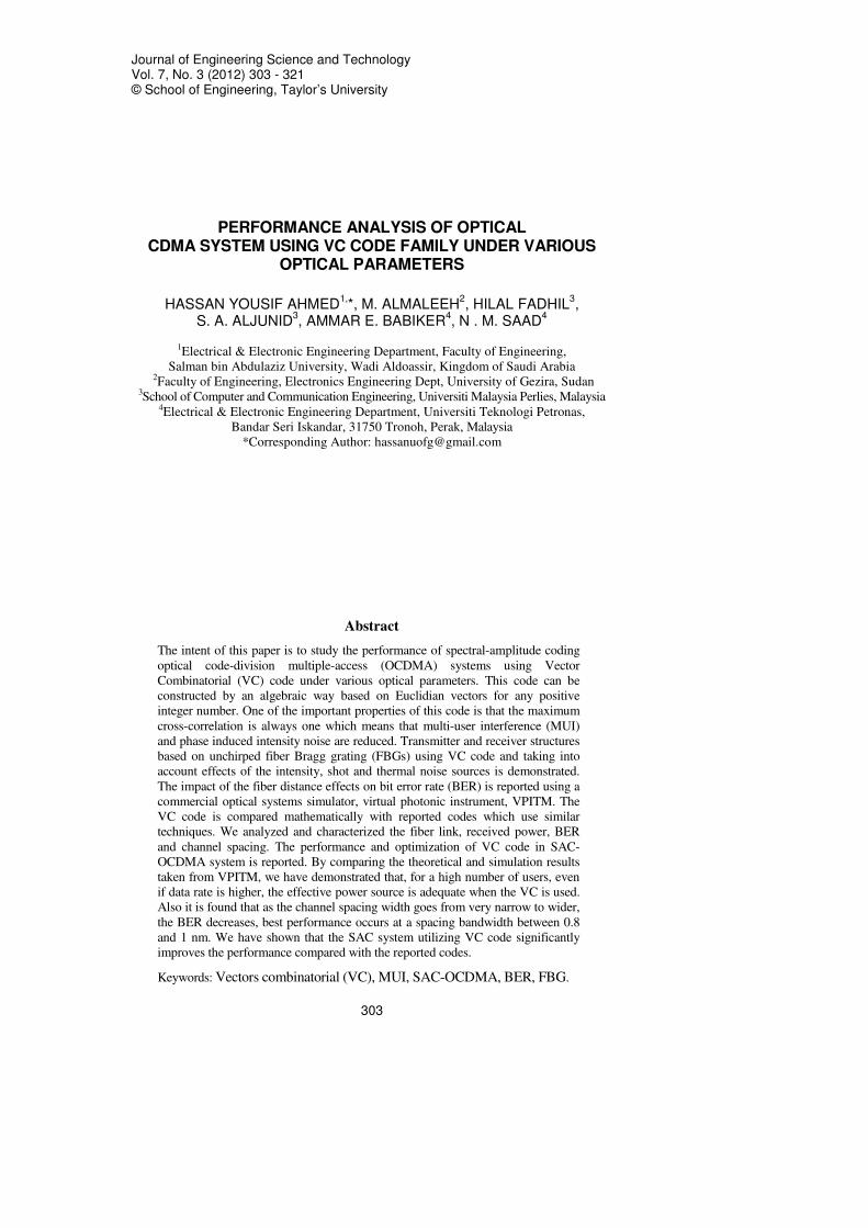
Journal of Engineering Science and Technology Vol. 7, No. 3 (2012) 303 - 321 © School of Engineering, Taylor’s University
303
PERFORMANCE ANALYSIS OF OPTICAL CDMA SYSTEM USING VC CODE FAMILY UNDER VARIOUS
OPTICAL PARAMETERS
HASSAN YOUSIF AHMED1,*, M. ALMALEEH
2, HILAL FADHIL
3,
S. A. ALJUNID3, AMMAR E. BABIKER
4, N . M. SAAD
4
1Electrical & Electronic Engineering Department, Faculty of Engineering,
Salman bin Abdulaziz University, Wadi Aldoassir, Kingdom of Saudi Arabia
2Faculty of Engineering, Electronics Engineering Dept, University of Gezira, Sudan 3School of Computer and Communication Engineering, Universiti Malaysia Perlies, Malaysia
4Electrical & Electronic Engineering Department, Universiti Teknologi Petronas,
Bandar Seri Iskandar, 31750 Tronoh, Perak, Malaysia
*Corresponding Author: [email protected]
Abstract
The intent of this paper is to study the performance of spectral-amplitude coding
optical code-division multiple-access (OCDMA) systems using Vector
Combinatorial (VC) code under various optical parameters. This code can be
constructed by an algebraic way based on Euclidian vectors for any positive
integer number. One of the important properties of this code is that the maximum
cross-correlation is always one which means that multi-user interference (MUI)
and phase induced intensity noise are reduced. Transmitter and receiver structures
based on unchirped fiber Bragg grating (FBGs) using VC code and taking into
account effects of the intensity, shot and thermal noise sources is demonstrated.
The impact of the fiber distance effects on bit error rate (BER) is reported using a
commercial optical systems simulator, virtual photonic instrument, VPITM. The
VC code is compared mathematically with reported codes which use similar
techniques. We analyzed and characterized the fiber link, received power, BER
and channel spacing. The performance and optimization of VC code in SAC-
OCDMA system is reported. By comparing the theoretical and simulation results
taken from VPITM, we have demonstrated that, for a high number of users, even
if data rate is higher, the effective power source is adequate when the VC is used.
Also it is found that as the channel spacing width goes from very narrow to wider,
the BER decreases, best performance occurs at a spacing bandwidth between 0.8
and 1 nm. We have shown that the SAC system utilizing VC code significantly
improves the performance compared with the reported codes.
Keywords: Vectors combinatorial (VC), MUI, SAC-OCDMA, BER, FBG.
304 Hassan Y. Ahmed et al.
Journal of Engineering Science and Technology June 2012, Vol. 7(3)
Nomenclatures
B Noise-equivalent electrical bandwidth of the receiver, Hz
dN Data bit of the Nth user
e Electron’s charge, Coulomb
h Planck’s constant
I Average photocurrent, A
I2 Power spectral density for I, W 2
piinI Phase induced intensity noise (PIIN), W
2
TotI Total noise power, W
2
thI Thermal noise, W/Hz
Ish Shot noise, W
KB Boltzmann’s constant
L VC code length
N Number of the active users
P Number of mapping users
Psr Effective power of a broadband source at the receiver, dBm
R Number of the remaining users after modulo operation
RL Receiver load resistor, Ω
Tn Absolute receiver noise temperature, K
u(v) Unit step function
V Column vector
Vc Central frequency of the original broad-band optical pulse, Hz
vi A vector
W Code weight
Greek Symbols
∆V Optical source bandwidth, Hz
η Quantum efficiency
ℜ photodiode responsivity
1. Introduction
Reliable networks with higher throughput, low cost and different classes of
services are required. The tremendous growth of the Internet has brought more
users online and thus consuming larger amounts of bandwidth. To realize the
demands for bandwidth and new services, a new technology must be deployed
and fiber optics is one such key technology. Optical fiber offers several
advantages over conventional media (e.g., coaxial cable and twisted pair).
Recently Optical Code Division Multiple Access (OCDMA) has been proposed as
an alternative to frequency- and time-based multiple and multiplexing methods
for next generation high speed optical fiber networks [1-4]. The SAC-OCDMA
systems have gained more attention since the MUI can be completely eliminated
by spectral coding. Many codes appeared in the literature aiming to support
optical networks with large numbers of users at different data rates [5-10].
However, some of these codes have much poorer cross correlation (e.g.,

Performance Analysis of Optical CDMA System Using VC Code Family 305
Journal of Engineering Science and Technology June 2012, Vol. 7(3)
Hadamard code [5]), or the number of available codes is quite restricted (e.g.
integer lattice exists for m and k where m and k need to be a co-prime (it is
enough if one is an even and the other is odd) [6], a prime number for modified
quadratic congruence (MQC) [7], a prime power for modified frequency hopping
(MFH) [8], an even natural numbers for modified double code (MDW) [9], and an
odd natural numbers for enhanced double weight (EDW) [10,11]. The
performance of OCDMA is limited by strong noise originated from other users
trying to use the medium simultaneously, referred to as Multi-user Interference
(MUI). In order to combat the MUI a proper detection scheme must be applied.
Although MUI can be cancelled by a balanced detection scheme, inherent
problems of noise still remain labelled as phase induced intensity noise (PIIN)
arising from the spontaneous emission from the broadband source.
Therefore, the distance was expected to influence the performance in two
means; loss and dispersion. At low transmission rates, the dispersion effect is not
significant, the loss would be dominant. Longer fiber optics provides a huge
dispersion and attenuation [9]; thus the bit error rate increases. In particular, the
relationship between BER and data rate is inversely proportional, which means as
the date rate increased, the BER becomes worse and vice versa. In this paper, we
have reviewed an efficient method to construct a new code family and its
properties for the SAC-OCDMA systems. This new code family not only
possesses ideal in-phase cross correlation, but also exists for a much wider
number of the weights for any users while the number of users is greater than the
weight plus one is satisfied regardless whether the number is even, odd, prime,
prime power, etc. We have proposed a new vector combinatorial (VC) code
family for the SAC-OCDMA systems that is characterized by (L, N, W, λ) with
length L, number of users N, weight W (number of marks) and cross correlation
(CC) λ. In recent years, FBGs have emerged as an enabling technology for many
light wave communications. Therefore, FBGs are more convenient for SAC-
OCDMA code applications [12].
The complementary detection scheme can be used to give accurate results
when the CC is fixed [5]. However, in order to increase the number of users for a
VC, a mapping technique must be applied. The mapping technique is a
mechanism used in [9, 13] in order to increase the number of users beyond the
basic number of users offered by the basic matrix for a specific weight. When
applying the mapping technique, the cross CC is no longer fixed, consequently,
the complementary detection technique cannot be used to give accurate results.
The detection technique proposed in [14] can be used even though the CC
between different users is not fixed. A novel encoder/decoder based on FBGs has
been proposed in [14]. Similarly we have designed the encoder-decoder structure
based on our new proposed codes. We have also analyzed the system by Gaussian
approximation taking into account the effects of PIIN, thermal noise and shot
noise. The rest of this paper is organized as follows. The family of newly
constructed codes is described in Section 2. Section 3 demonstrates the
transmitter and receiver structure. Section 4 presents the analytic results of system
performance. The property of this code is discussed from the view of comparison
in Section 5. Theoretical analysis and simulation results are drawn in Section 6.
Finally, we have the conclusion in Section 7.
306 Hassan Y. Ahmed et al.
Journal of Engineering Science and Technology June 2012, Vol. 7(3)
2. The VC Code Construction and Properties
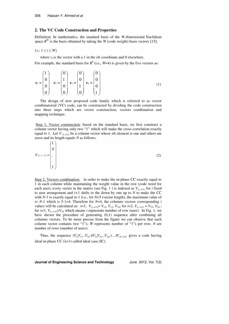
Definition: In mathematics, the standard basis of the W-dimensional Euclidean
space RW
is the basis obtained by taking the W (code weight) basis vectors [15]:
vi: 1 ≤ i ≤ W
where vi is the vector with a 1 in the ith coordinate and 0 elsewhere.
For example, the standard basis for R4 (i.e., W=4) is given by the five vectors as:
=
0
0
0
1
1v
=
0
0
1
0
2v
=
0
1
0
0
3v
=
1
0
0
0
4v (1)
The design of new proposed code family which is referred to as vector
combinatorial (VC) code, can be constructed by dividing the code construction
into three steps which are vector construction, vectors combination and
mapping technique.
Step 1, Vector construction: based on the standard basis, we first construct a
column vector having only two “1” which will make the cross-correlation exactly
equal to 1. Let V (i, i+1) be a column vector whose ith element is one and others are
zeros and its length equals N as follows.
=+
1
.
.
0
1
)1,( iiV (2)
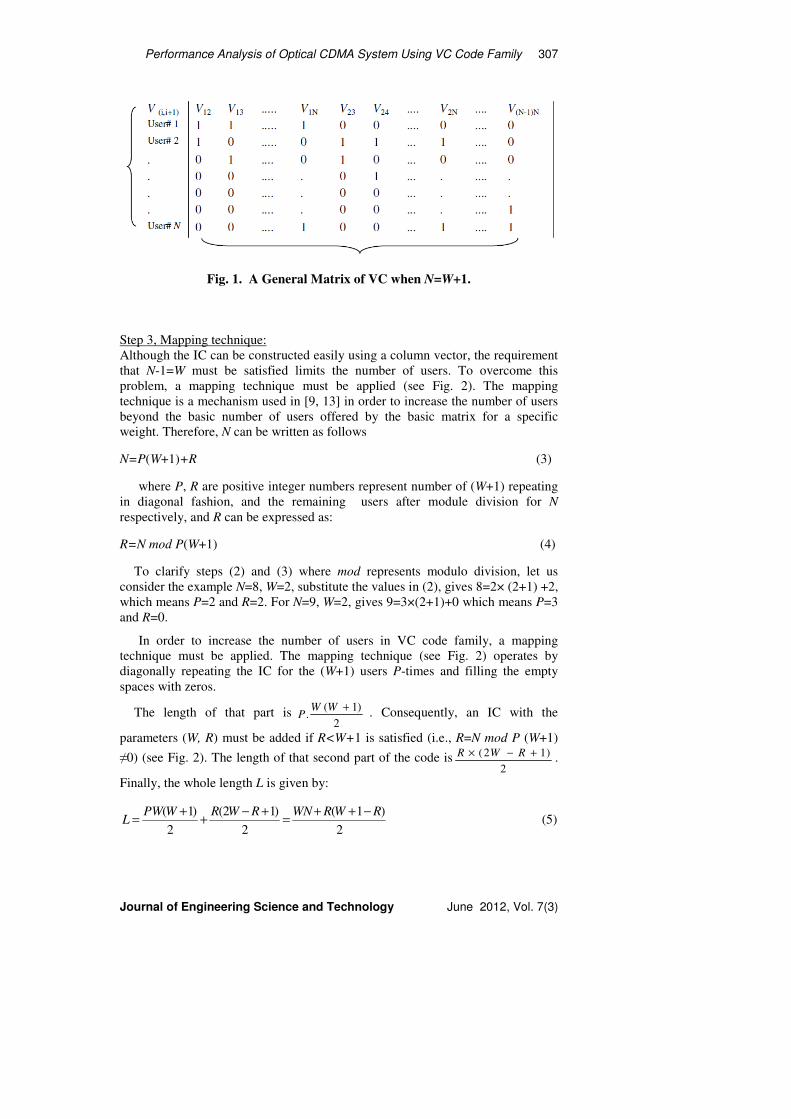
Step 2, Vectors combination: in order to make the in-phase CC exactly equal to
1 in each column while maintaining the weight value in the row (code word for
each user), every vector in the matrix (see Fig. 1 ) is indexed as V(i, i+1) for i fixed
to user arrangement and i+1 shifts to the down by one up to N to make the CC
with N-1 is exactly equal to 1 (i.e., for N=5 (vector length), the maximum value of
i= N-1 which is 5-1=4. Therefore for N=4, the columns vectors corresponding i
values will be calculated as: i=1; V(i, i+1)= V12, V13, V14; for i=2, V(i, i+1) = V23, V34 ;
for i=3, V(i, i+1)=V34 which means i represents number of row (user). In Fig. 1, we
have shown the procedure of generating (0,1) sequence after combining all
columns vectors. To be more precise from the figure we can observe that each
column vector contains two “1”s; W represents number of “1”s per row; N are
number of rows (number of users).
Thus, the sequence NNNN VVVVVVV )1(2242311312 )....(...)(...( − gives a code having
ideal in-phase CC (λ=1) called ideal case (IC).
Performance Analysis of Optical CDMA System Using VC Code Family 307
Journal of Engineering Science and Technology June 2012, Vol. 7(3)
Fig. 1. A General Matrix of VC when N=W+1.
Step 3, Mapping technique:
Although the IC can be constructed easily using a column vector, the requirement
that N-1=W must be satisfied limits the number of users. To overcome this
problem, a mapping technique must be applied (see Fig. 2). The mapping
technique is a mechanism used in [9, 13] in order to increase the number of users
beyond the basic number of users offered by the basic matrix for a specific
weight. Therefore, N can be written as follows
N=P(W+1)+R (3)
where P, R are positive integer numbers represent number of (W+1) repeating
in diagonal fashion, and the remaining users after module division for N
respectively, and R can be expressed as:
R=N mod P(W+1) (4)
To clarify steps (2) and (3) where mod represents modulo division, let us
consider the example N=8, W=2, substitute the values in (2), gives 8=2× (2+1) +2,
which means P=2 and R=2. For N=9, W=2, gives 9=3×(2+1)+0 which means P=3
and R=0.
In order to increase the number of users in VC code family, a mapping
technique must be applied. The mapping technique (see Fig. 2) operates by
diagonally repeating the IC for the (W+1) users P-times and filling the empty
spaces with zeros.
The length of that part is2
)1(.
+WWP . Consequently, an IC with the
parameters (W, R) must be added if R<W+1 is satisfied (i.e., R=N mod P (W+1)
≠0) (see Fig. 2). The length of that second part of the code is2
)12( +−× RWR .
Finally, the whole length L is given by:
2
)1(
2
)12(
2
)1( RWRWNRWRWPWL
−++=
+−+
+= (5)

308 Hassan Y. Ahmed et al.
Journal of Engineering Science and Technology June 2012, Vol. 7(3)
In Table 1, W = 3 and N = 9 by using (4), (5) gives 9=2× (3+1) +1, resulting
P=2 and R=1 which means we have to repeat the IC two times (P=2) in diagonal
fashion resulting in 8 users and add one more user (R=1) after user#8 in diagonal
fashion as well. By using (6) L= 9×3+1(3-1+1)/2, the length will be 15. In Table
1, there are three groups, the first group of the code (the first six columns) is the
VCC with the parameters (3,4) which means W=3 and N=4 having a CC equal to
1, the second group (the columns from 7 to 12) is a replica from the first group
with the parameters (3, 4), the third group (the columns 13, 14, 15) is the VCC
with the parameters (3,1) which means W=3 and N=1(i.e., R=N) since the
condition R<W+1 (1<4) is satisfied having a CC equal to 1.
Fig. 2. A Graphic Representation of Mapping Techniques for N= P (W+1)+R.
Table 1. VC Code for N > W+1(N=9, W=3)
3. Structure of Transmitter and Receiver
3.1. Structure of transmitter and receiver based on FBG
As shown in Table 1, the VC code words of 9 users are obtained by applying the
mapping technique. Figure 3 represents the corresponding amplitude spectra of
the code sequences, where the solid lines represent one chip and the dash lines
represent zero chips.
In the VC family, the code construction depends on the number of users, so if
the number of users N is greater than the weight plus one (N>W+1), a mapping
technique must be applied resulting in the CC no longer being fixed. A Hybrid
Wavelength-Division-Multiplexing/Spectral-Amplitude-Coding Optical CDMA
System (WDM/SAC) is proposed in [14], where balance detection can be
achieved even though the CC value is not fixed.

Performance Analysis of Optical CDMA System Using VC Code Family 309
Journal of Engineering Science and Technology June 2012, Vol. 7(3)
Fig. 3. Spectral of WS-VC Code for 9 Users.
In Fig. 4, similarly we have used the method given in [14] to design the
transmitter and receiver structure based on user#1 (111000000000000). ON-OFF
shift keying modulation is used to modulate the information bits for the desired
user and then the result of the optical signal is directed to FBGs, where each chip
of the VC has been attributed by a specific wavelength (λ1 λ2 λ3). The decoding
process is similar to conventional SAC systems, and could be achieved by passing
the receiving signal through two FBG arrays assigned by the weight (λ1 λ2 λ3)
and its complementary (λ4 λ5 λ6) , then recover the signal differentially to
reproduce the desired signal [14]. Note that only codes that correlate with
intended receiver are circulated to both photo-detectors. Codes that do not
correlate pass without getting detected.
Fig. 4. Structure of (a) Encoder and (b) Decoder for
User # 1using VC with Mapping Using FBGs.
310 Hassan Y. Ahmed et al.
Journal of Engineering Science and Technology June 2012, Vol. 7(3)
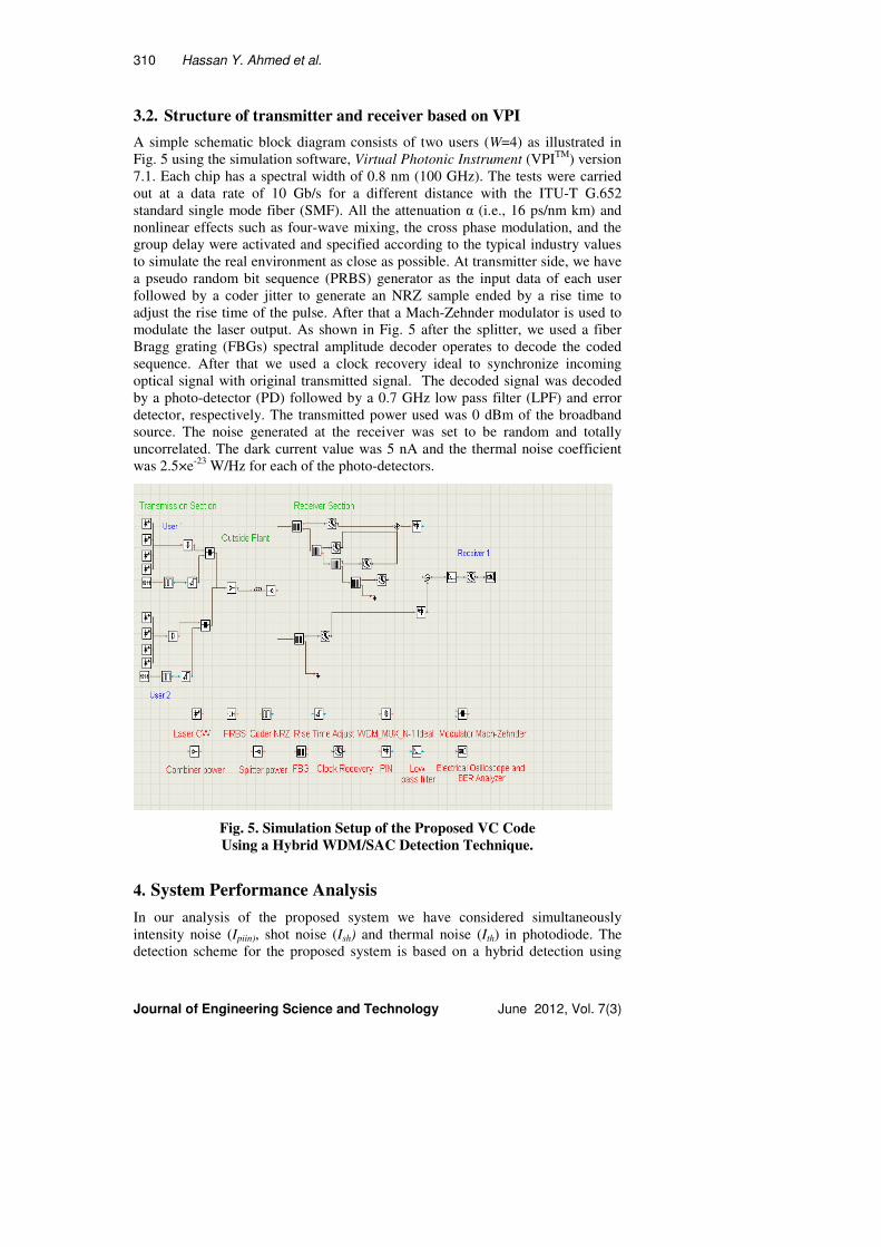
3.2. Structure of transmitter and receiver based on VPI
A simple schematic block diagram consists of two users (W=4) as illustrated in
Fig. 5 using the simulation software, Virtual Photonic Instrument (VPITM
) version
7.1. Each chip has a spectral width of 0.8 nm (100 GHz). The tests were carried
out at a data rate of 10 Gb/s for a different distance with the ITU-T G.652
standard single mode fiber (SMF). All the attenuation α (i.e., 16 ps/nm km) and
nonlinear effects such as four-wave mixing, the cross phase modulation, and the
group delay were activated and specified according to the typical industry values
to simulate the real environment as close as possible. At transmitter side, we have
a pseudo random bit sequence (PRBS) generator as the input data of each user
followed by a coder jitter to generate an NRZ sample ended by a rise time to
adjust the rise time of the pulse. After that a Mach-Zehnder modulator is used to
modulate the laser output. As shown in Fig. 5 after the splitter, we used a fiber
Bragg grating (FBGs) spectral amplitude decoder operates to decode the coded
sequence. After that we used a clock recovery ideal to synchronize incoming
optical signal with original transmitted signal. The decoded signal was decoded
by a photo-detector (PD) followed by a 0.7 GHz low pass filter (LPF) and error
detector, respectively. The transmitted power used was 0 dBm of the broadband
source. The noise generated at the receiver was set to be random and totally
uncorrelated. The dark current value was 5 nA and the thermal noise coefficient
was 2.5×e-23
W/Hz for each of the photo-detectors.
Fig. 5. Simulation Setup of the Proposed VC Code
Using a Hybrid WDM/SAC Detection Technique.
4. System Performance Analysis
In our analysis of the proposed system we have considered simultaneously
intensity noise (Ipiin), shot noise (Ish) and thermal noise (Ith) in photodiode. The
detection scheme for the proposed system is based on a hybrid detection using
Performance Analysis of Optical CDMA System Using VC Code Family 311
Journal of Engineering Science and Technology June 2012, Vol. 7(3)
optical filter followed by photo-detector. Gaussian approximation is used for the
calculation of BER as in [7, 8, 16]. The SNR is calculated at the receiver side and
for each user there is only one photodiode, the current flow through the
photodiode is denoted by I.
Let CN(i) denote the ith element of the Nth VC code sequence. Assume user#
(f, g) is the desired user belong to the ideal case (N=W+1) and user# (z, t) does
not belong to ideal case (N=P(W+1)+R), the correlation functions of each user is
given by:
( )( )
=
,0
,1
,
,,,0
1
W
tzgfPD ( )( ) RWPNtg
WNtgzf
zf
++=≠
+==≠
=
1for ,
1for ,, (6)
and
( )( )
−=
,0
,1
,0
,,,1
1 WtzgfPD ( )( ) RWPNtg
WNtgzf
tgzf
++=≠
+==≠
==
1for ,
1for ,, (7)
Thus
( )( )
==
=−
−
else ,0
, ,
1
,,,,,, 2
1
tgzfW
W
tzgfPDtzgfPD (8)
When a broad-band pulse is input into the group of FBGs, the incoherent light
fields are mixed and incident upon a photo-detector, the phase noise of the fields
causes an intensity noise term in the photo-detector output. The coherence time of
a thermal source (τc ) is given by [8]:
2
0
0
2
)(
)(
∫
∫∞
∞
=
dvvG
dvvG
Cτ (9)
Where G(v) is the single sideband power spectral density (PSD) of the source.
The Q-factor performance provides a qualitative description of the optical
receiver performance, the performance of an optical receiver depends on the
signal-to-noise ratio (SNR). The Q-factor proposes the minimum SNR required to
obtain a specific BER for a given signal. The SNR of an electrical signal is
defined as the average signal power to noise power [SNR = I2/I
2Tot], where I
2Tot is
defined as the variance of the noise source (note: the effect of the receiver’s dark
current and amplification noises are neglected in the analysis of the proposed
system), given by
I2
Tot = Ipiin + Ish + Ith
which also can be written as:
I2
Tot = 2eIB + I2Bτc +4KB TnBRL (10)
312 Hassan Y. Ahmed et al.
Journal of Engineering Science and Technology June 2012, Vol. 7(3)
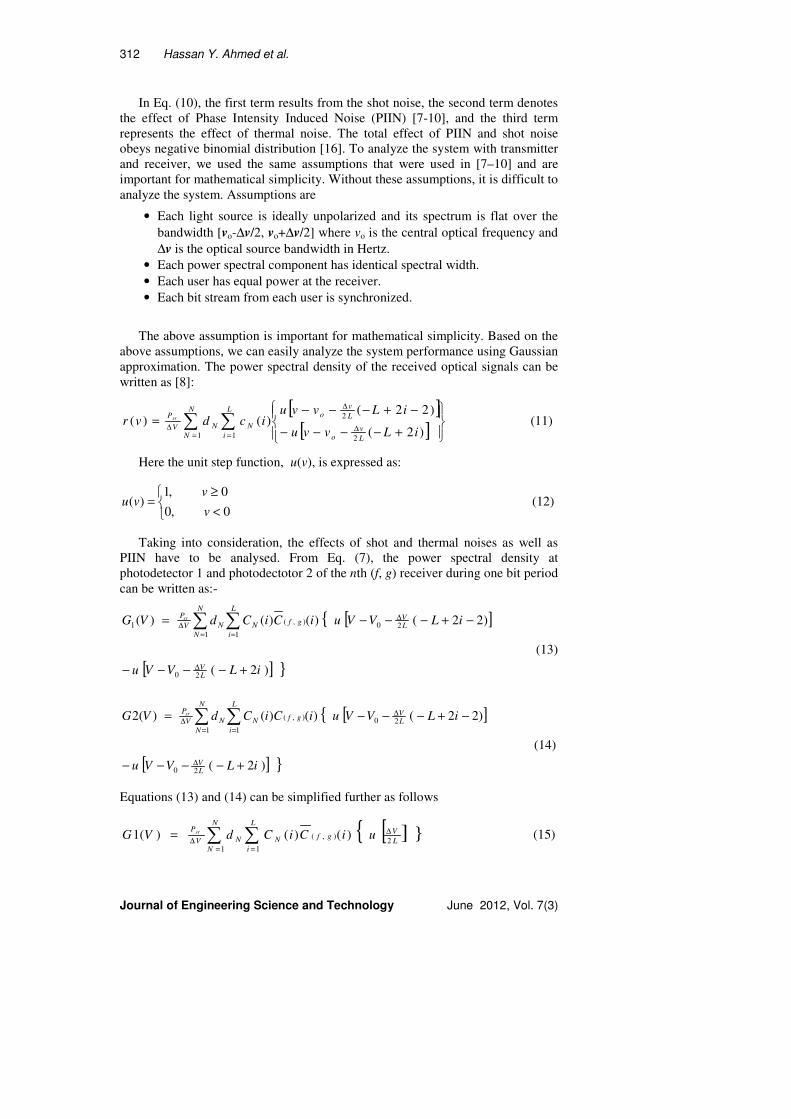
In Eq. (10), the first term results from the shot noise, the second term denotes
the effect of Phase Intensity Induced Noise (PIIN) [7-10], and the third term
represents the effect of thermal noise. The total effect of PIIN and shot noise
obeys negative binomial distribution [16]. To analyze the system with transmitter
and receiver, we used the same assumptions that were used in [7–10] and are
important for mathematical simplicity. Without these assumptions, it is difficult to
analyze the system. Assumptions are
• Each light source is ideally unpolarized and its spectrum is flat over the
bandwidth [vo-∆v/2, vo+∆v/2] where vo is the central optical frequency and
∆v is the optical source bandwidth in Hertz.
• Each power spectral component has identical spectral width.
• Each user has equal power at the receiver.
• Each bit stream from each user is synchronized.
The above assumption is important for mathematical simplicity. Based on the
above assumptions, we can easily analyze the system performance using Gaussian
approximation. The power spectral density of the received optical signals can be
written as [8]:
[ ][ ]∑ ∑
= =∆
∆
∆
+−−−−
−+−−−=
N
N
L
i L
vo
L
vo
NNV
P
iLvvu
iLvvuicdvr sr
1 1 2
2
)2(
)22()()( (11)
Here the unit step function, u(v), is expressed as:
<
≥=
0,0
0,1)(
v
vvu (12)
Taking into consideration, the effects of shot and thermal noises as well as
PIIN have to be analysed. From Eq. (7), the power spectral density at
photodetector 1 and photodectotor 2 of the nth (f, g) receiver during one bit period
can be written as:-
][
] [ )2(
)22()()()(
20
20
1 1
),(1
iLVVu
iLVVuiCiCdVG
LV
LV
N
N
L
i
gfNNV
Psr
+−−−−
−+−−−=
∆
∆
= =∆ ∑ ∑
(13)
][
] [ )2(
)22()()()(2
20
20
1 1
),(
iLVVu
iLVVuiCiCdVG
LV
LV
N
N
L
i
gfNNV
Psr
+−−−−
−+−−−=
∆
∆
= =∆ ∑ ∑
(14)
Equations (13) and (14) can be simplified further as follows
[ ]2
1 1
),( )()()(1L
VN
N
L
i
gfNNV
PuiCiCdVG sr ∆
= =∆ ∑ ∑= (15)
Performance Analysis of Optical CDMA System Using VC Code Family 313
Journal of Engineering Science and Technology June 2012, Vol. 7(3)
[ ]2
1 1
),( )()()(2L
VN
N
L
i
gfNNV
PuiCiCdVG sr ∆
= =∆ ∑ ∑= (16)
In Eqs. (14) and (15), the data bit of the Nth user, dN, carries the value of
either “1” or “0.” Therefore the photo-detector current can be calculated by
integrating process as follows:
dvvGI )(0
11 ∫∞
= (17)
and
dvvGI )(0
22 ∫∞
= (18)
By using the properties of VC code to obtain pure photocurrent after subtract
process upon the photo-detectors, Eqs. (17) and (18) become:
I=I2-I1= dvvG )(0
1∫∞
- dvvG )(0
2∫∞
(19)
After integrating and subtraction processes, the photocurrent can be expressed as:
I = ℜ WL
Psr (20)
chV
eη=ℜ (21)
Since the noises in photodetector 1 and 2 are independent, the power of noise
sources that exist in the photocurrent can be written as [8]:
⟩⟨+⟩⟨+⟩⟨=⟩⟨ 2222
thshpiinTot IIII (22)
From Eq. (22):
L
nb
R
BTK
cc BIBIIIeBI4
2
2
21
2
121
2)(2 ++++=⟩⟨ ττ (23)
Therefore
L
nb
R
BTKdvvGBdvvGBdvvGdvvGeBI
4
0
2
2
2
0
2
1
2
0 021
2 )()()()(2 ∫∫∫ ∫∞∞
∞ ∞
+ℜ+ℜ+
+ℜ=⟩⟨ (24)
From Eq. (10), when all the users are transmitting bit ‘’1’’ using the average
value as LNWN
N Nc ≈∑ =1 and the noise power can be written as:
[ ] [ ]L
nb
LNW
VL
P
L
P
TotR
BTK
N
WNBNWNeBI srsr
4
)1(
)1(.)1()1((2
222 +
−+
+−⋅ℜ+−++−=⟩⟨
∆ (25)
314 Hassan Y. Ahmed et al.
Journal of Engineering Science and Technology June 2012, Vol. 7(3)
Noting that the probability of sending bit ‘1’ at any time for each user is a 21
[7-8, 16], then Eq. (25) becomes:
[ ] [ ]L
nb
LV
WNBP
L
BeP
TotR
BTKWRPNWNI srsr
4)/()22()22( 2
22
2
2 +++−++−=⟩⟨∆
ℜℜ (26)
From Eqs. (20) and (26), the average of SNR is as shown as in Eqs. (27) and (28)
SNR=⟩⟨
−
2
)( 212
TotI
II (27)
[ ] [ ]LR
BnKBT
LV
NBsrP
L
BesrP
L
WsrP
RPNWWN
SNR4
22
22
2
222
/)1(2)1( ++−+++−∆
ℜℜ
ℜ
= (28)
where ℜ is the photodiode responsivity. The Bit Error Rate (BER) is
computed from the SNR using Gaussian approximation as [7-8, 16].
BER = 0.5 erfc 8/SNR (29)
For numerical simulations, the following parameters are used: Psr= -10 dBm is
the optical received power, ∆V=3.75 THz is the line width of the broad band
source, B=311 MHz is the receiver noise-equivalent electrical bandwidth, Tn= 300
K, RL= 1030 Ω , the bit-rate is at 622 Mb/s, η =0.6 is the photodiode quantum
efficiency and λ=1550 nm is the operating wavelength [7-10].
5. Code Evaluation and Comparison
A series of code family with ideal in-phase CC is achieved. For comparison, the
properties of the VC, MQC, MDW, MFH and Hadamard are listed in Table 2. It
shows that VC codes exist for any positive integer (regardless whether it is even,
odd, prime, etc), while MDW exists for even n weights, Hadamard codes exist
only when the weight is 2m-1
where m≥2, MQC and MFH exist for a prime
number p and a prime power Q given by Q= pn where n
is a positive integer,
respectively. The table also shows that the VC codes have an ideal cross
correlation while the Hadamard codes have an increasing value of cross
correlation as the number of users increased.
The performance of the VC in terms of code length is also compared with that
of reported codes. For comparison, the properties of VC, MQC, and MFH are
listed in Table 3. Table 3 shows the codes lengths required by MQC (W=6), MFH
(W=6) and VC (W=2, P=8, R=1) to support 25 users. From the table we can
observe that, VC provides better performance than other codes for same number
of users in terms of code length. Long length is a disadvantage since the code is
subject to either very wide band source or narrow filter bandwidths are required
while short length limits the freedom of code selection. The VC exists for
practical code length that is neither too long nor too short.
Performance Analysis of Optical CDMA System Using VC Code Family 315
Journal of Engineering Science and Technology June 2012, Vol. 7(3)
Table 2. SAC-OCDMA Codes Comparison.
Table 3. Comparison of VC, MQC and MFH
for the Same Number of Users, N = 25.
6. Results and Discussion
The eye pattern diagrams for VC code for a different fiber links is shown in
Fig. 6. The eyes diagram illustrated in Fig. 6 clearly explain that the VC code
using a short fiber link (Fig. 6(b)) gives better performance, having a larger eye
opening compared to a long fiber link (Fig. 6(a)). The effect of varying the
fiber length is related to the power level of the received power. A longer length
of fiber has higher insertion loss, thus smaller output power. As a matter of fact,
when the fiber length decreases, the data rate should increases to recover a
similar degradation of the signal form. Thus, in order to design and optimize
link parameters, the maximum fiber length should be defined as short as
possible, to obtain high data rate and to achieve a desired system performance.
The equivalent simulated BER for VC code for a different fiber links is shown
in Fig. 5. In Figs. 6(a) and (b), the estimated BERs for VC are 10-29
and 10-22
for 25 and 50 km respectively which are satisfactory in practical
communication systems.

316 Hassan Y. Ahmed et al.
Journal of Engineering Science and Technology June 2012, Vol. 7(3)
(a)
(b)
Fig. 6. Eye Diagram of (a) One of the VC Channels Using a 50 km Fiber
Link, (b) One of the VC Channels Using a 25 km Fiber Link, at 10 Gbit/s.
Figure 7 shows the BER variations with the effective power for the VC code when
W=4, for a 25 km at 10Gbit/s. It demonstrates the typical linear dependence of the
signal power variation due to additive noise and the laser power in dBm. We have
found that in order to transmit over a dispersive fiber, a dispersion compensation
techniques have to be used. However, the transmission distance remains limited due to
the attenuation in the fiber and the noise generation in the detectors.

Performance Analysis of Optical CDMA System Using VC Code Family 317
Journal of Engineering Science and Technology June 2012, Vol. 7(3)
Fig. 7. BER versus Received Power Psr for a 25 km Fiber Link at 10 Gbit/s.
Figure 8 shows the relation between the number of active users and the SNR
when the parameters used for the VC, MQC, MFH and Hadamard codes are W=6,
14, 17, 64 respectively while the P=3, R=1 for VC code. In this figure, the
effective power from each user is -10dBm taking into account the effects of
intensity noise, shot noise and thermal noise. It is shown that the VC code gives
much higher SNRs than MQC, MFH, and Hadamard. With a big values of P and
R higher SNR can be obtained even for small weight while accommodates high
number of active users.
0 20 40 60 80 100 120 140 160 180 20010
0
101
102
103
104
Number of Simultaneous Users
Sig
nal to
nois
e r
atio (
SN
R)
VC code (W=6, P=3, R=1)
MQC code (W=14)
MFH code (W=17)
Hadamard code
105
Fig. 8. SNRs versus the Number of Active Users when Psr = - 10 dBm.
318 Hassan Y. Ahmed et al.
Journal of Engineering Science and Technology June 2012, Vol. 7(3)
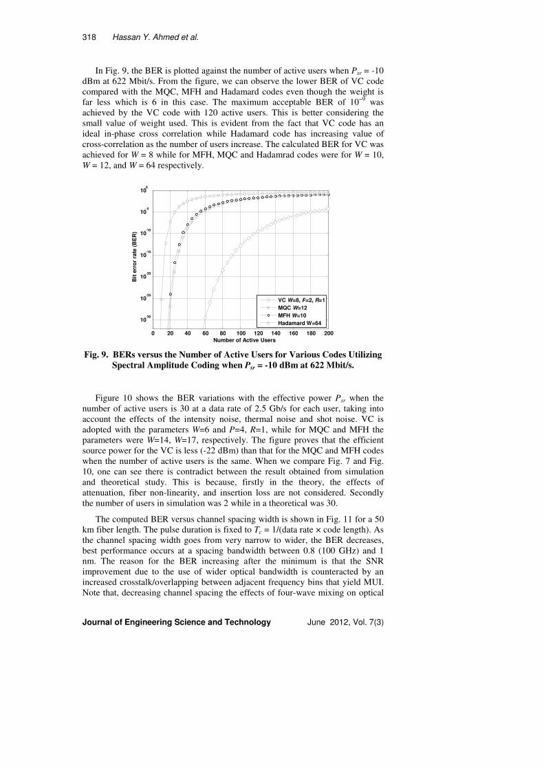
In Fig. 9, the BER is plotted against the number of active users when Psr = -10
dBm at 622 Mbit/s. From the figure, we can observe the lower BER of VC code
compared with the MQC, MFH and Hadamard codes even though the weight is
far less which is 6 in this case. The maximum acceptable BER of 10−9
was
achieved by the VC code with 120 active users. This is better considering the
small value of weight used. This is evident from the fact that VC code has an
ideal in-phase cross correlation while Hadamard code has increasing value of
cross-correlation as the number of users increase. The calculated BER for VC was
achieved for W = 8 while for MFH, MQC and Hadamrad codes were for W = 10,
W = 12, and W = 64 respectively.
0 20 40 60 80 100 120 140 160 180 200
10-30
10-25
10-20
10-15
Number of Active Users
Bit
err
or
rate
(B
ER
)
VC W=8, P=2, R=1
MQC W=12
MFH W=10
Hadamard W=64
10-10
10-5
100
Fig. 9. BERs versus the Number of Active Users for Various Codes Utilizing
Spectral Amplitude Coding when Psr = -10 dBm at 622 Mbit/s.
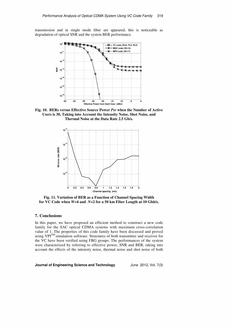
Figure 10 shows the BER variations with the effective power Psr when the
number of active users is 30 at a data rate of 2.5 Gb/s for each user, taking into
account the effects of the intensity noise, thermal noise and shot noise. VC is
adopted with the parameters W=6 and P=4, R=1, while for MQC and MFH the
parameters were W=14, W=17, respectively. The figure proves that the efficient
source power for the VC is less (-22 dBm) than that for the MQC and MFH codes
when the number of active users is the same. When we compare Fig. 7 and Fig.
10, one can see there is contradict between the result obtained from simulation
and theoretical study. This is because, firstly in the theory, the effects of
attenuation, fiber non-linearity, and insertion loss are not considered. Secondly
the number of users in simulation was 2 while in a theoretical was 30.
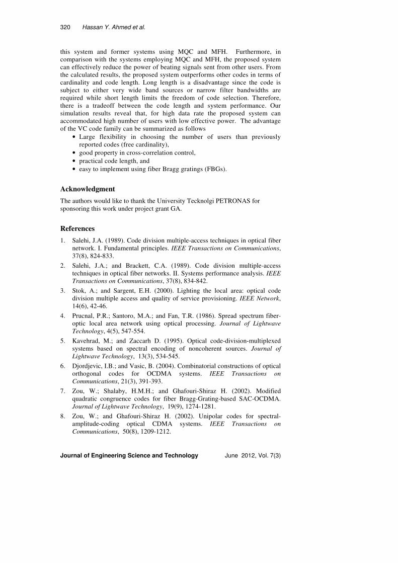
The computed BER versus channel spacing width is shown in Fig. 11 for a 50
km fiber length. The pulse duration is fixed to Tc = 1/(data rate × code length). As
the channel spacing width goes from very narrow to wider, the BER decreases,
best performance occurs at a spacing bandwidth between 0.8 (100 GHz) and 1
nm. The reason for the BER increasing after the minimum is that the SNR
improvement due to the use of wider optical bandwidth is counteracted by an
increased crosstalk/overlapping between adjacent frequency bins that yield MUI.
Note that, decreasing channel spacing the effects of four-wave mixing on optical
Performance Analysis of Optical CDMA System Using VC Code Family 319
Journal of Engineering Science and Technology June 2012, Vol. 7(3)
transmission and in single mode fiber are appeared, this is noticeable as
degradation of optical SNR and the system BER performance.
-40 -35 -30 -25 -20 -15 -10 -5 0
10-30
10-25
10-20
10-15
10-10
10-5
100
Effective Power from Each User: (dBm)
BE
R
VC code (W=6, P=4, R=2)
MQC code (W=14)
MFH code (W=17)
Fig. 10. BERs versus Effective Source Power Psr when the Number of Active
Users is 30, Taking into Account the Intensity Noise, Shot Noise, and
Thermal Noise at the Data Rate 2.5 Gb/s.
0 0.2 0.4 0.6 0.8 1 1.2 1.4 1.6 1.8 2
10-25
10-20
10-15
10-10
Channel spacing (nm)
Bit
err
or
rate
(B
ER
)
Fig. 11. Variation of BER as a Function of Channel Spacing Width
for VC Code when W=4 and N=2 for a 50 km Fiber Length at 10 Gbit/s.
7. Conclusions
In this paper, we have proposed an efficient method to construct a new code
family for the SAC optical CDMA systems with maximum cross-correlation
value of 1. The properties of this code family have been discussed and proved
using VPITM
simulation software. Structures of both transmitter and receiver for
the VC have been verified using FBG groups. The performances of the system
were characterized by referring to effective power, SNR and BER, taking into
account the effects of the intensity noise, thermal noise and shot noise of both
320 Hassan Y. Ahmed et al.
Journal of Engineering Science and Technology June 2012, Vol. 7(3)
this system and former systems using MQC and MFH. Furthermore, in
comparison with the systems employing MQC and MFH, the proposed system
can effectively reduce the power of beating signals sent from other users. From
the calculated results, the proposed system outperforms other codes in terms of
cardinality and code length. Long length is a disadvantage since the code is
subject to either very wide band sources or narrow filter bandwidths are
required while short length limits the freedom of code selection. Therefore,
there is a tradeoff between the code length and system performance. Our
simulation results reveal that, for high data rate the proposed system can
accommodated high number of users with low effective power. The advantage
of the VC code family can be summarized as follows
• Large flexibility in choosing the number of users than previously
reported codes (free cardinality),
• good property in cross-correlation control,
• practical code length, and
• easy to implement using fiber Bragg gratings (FBGs).
Acknowledgment
The authors would like to thank the University Tecknolgi PETRONAS for
sponsoring this work under project grant GA.
References
1. Salehi, J.A. (1989). Code division multiple-access techniques in optical fiber
network. I. Fundamental principles. IEEE Transactions on Communications,
37(8), 824-833.
2. Salehi, J.A.; and Brackett, C.A. (1989). Code division multiple-access
techniques in optical fiber networks. II. Systems performance analysis. IEEE
Transactions on Communications, 37(8), 834-842.
3. Stok, A.; and Sargent, E.H. (2000). Lighting the local area: optical code
division multiple access and quality of service provisioning. IEEE Network,
14(6), 42-46.
4. Prucnal, P.R.; Santoro, M.A.; and Fan, T.R. (1986). Spread spectrum fiber-
optic local area network using optical processing. Journal of Lightwave
Technology, 4(5), 547-554.
5. Kavehrad, M.; and Zaccarh D. (1995). Optical code-division-multiplexed
systems based on spectral encoding of noncoherent sources. Journal of
Lightwave Technology, 13(3), 534-545.
6. Djordjevic, I.B.; and Vasic, B. (2004). Combinatorial constructions of optical
orthogonal codes for OCDMA systems. IEEE Transactions on
Communications, 21(3), 391-393.
7. Zou, W.; Shalaby, H.M.H.; and Ghafouri-Shiraz H. (2002). Modified
quadratic congruence codes for fiber Bragg-Grating-based SAC-OCDMA.
Journal of Lightwave Technology, 19(9), 1274-1281.
8. Zou, W.; and Ghafouri-Shiraz H. (2002). Unipolar codes for spectral-
amplitude-coding optical CDMA systems. IEEE Transactions on
Communications, 50(8), 1209-1212.
Performance Analysis of Optical CDMA System Using VC Code Family 321
Journal of Engineering Science and Technology June 2012, Vol. 7(3)
9. Aljunid, S.A.; Ismail, M.; Ramli, A.R.; Ali, B.M.; and Abdullah, M.K.
(2004). A new family of optical code sequences for spectral-amplitude-
coding optical CDMA systems. IEEE Photonics Technology Letters, 16(10),
2383-2385.
10. Abdullah, M.K.; Hasoon, F.N.; Aljunid, S.A.; Shaari, S. (2008). Performance
of OCDMA systems with new spectral direct detection (SDD) technique
using enhanced double weight (EDW) code. Optics Communications,
281(18), 4658-4662.
11. Hasoon, F.N.; Aljunid, S.A.; Abdullah, M.K.; and Shaari, S. (2006). Spectral
amplitude coding OCDMA systems using enhanced double weight code.
Journal of Engineering Science and Technology (JESTEC), 1(2), 192-202.
12. Hill, K.O.; and Meltz, G.. (1997). Fiber Bragg grating technology fundamentals
and overview. Journal of Lightwave Technology, 15(8), 1263-1276.
13. Green, P.E. (1993). Fiber optic networks. Prentice Hall.
14. Yang, C.C. (2005). Hybrid wavelength-division multiplexing/spectral-
amplitude-coding optical CDMA system. IEEE Photonics Technology
Letters, 17(6), 1343-1345.
15. Kelley, J.L. (1975). General topology. Springer, ISBN 0-387-90125-6.
16. Goodman, J.W. (1985). Statistical optics. New York: Wiley-Interscience.