Embed Size (px)
Citation preview
PEARSON EDEXCEL INTERNATIONAL AS/A LEVEL
PHYSICSLab Book
M01-iASAL_PHYS_LAB_44754_001-080.indd 1 21/05/2018 15:11
Unc
orre
cted
pro
of, a
ll co
nten
t sub
ject
to c
hang
e at
pub
lishe
r dis
cret
ion.
Not
for r
esal
e, c
ircul
atio
n or
dis
tribu
tion
in w
hole
or i
n pa
rt. ©
Pea
rson
201
8
Published by Pearson Education Limited, 80 Strand, London, WC2R 0RL.
www.pearsonglobalschools.com
Copies of official specifications for all Pearson Edexcel qualifications may be found on the website: https://qualifications.pearson.com
Text © Pearson Education Limited 2018Designed by Tech-Set Ltd, Gateshead, UKEdited by Stephanie White and Jane ReadTypeset by Tech-Set Ltd, Gateshead, UKOriginal illustrations © Pearson Education Limited 2018Cover design by Pearson Education Limited 2018
The right of Steve Adams and Keith Bridgeman to be identified as authors of this work has been asserted by them in accordance with the Copyright, Designs and Patents Act 1988.
First published 2018
21 20 19 1810 9 8 7 6 5 4 3 2 1
British Library Cataloguing in Publication DataA catalogue record for this book is available from the British LibraryISBN 9781292244754
A note from the Publishers: found on the website: www.edexcel.comWhile the Publishers have made every attempt to ensure that advice on the qualification and its assessment is accurate, the official specification and associated assessment guidance materials are the only authoritative source of information and should always be referred to for definitive guidance. Pearson examiners have not contributed to any sections in this resource relevant to examination papers for which they have responsibility. Examiners will not use this resource as a source of material for any assessment set by Pearson.
Copyright noticeAll rights reserved. No part of this publication may be reproduced in any form or by any means (including photocopying or storing it in any medium by electronic means and whether or not transiently or incidentally to some other use of this publication) without the written permission of the copyright owner, except in accordance with the provisions of the Copyright, Designs and Patents Act 1988 or under the terms of a licence issued by the Copyright Licensing Agency, Barnard’s Inn, 86 Fetter Lane, London EC4A 1EN (www.cla.co.uk). Applications for the copyright owner’s written permission should be addressed to the publisher.
Neither Pearson, Edexcel nor the authors take responsibility for the safety of any activity. Before doing any practical activity you are legally required to carry out your own risk assessment. In particular, any local rules issued by your employer must be obeyed, regardless of what is recommended in this resource. Where students are required to write their own risk assessments they must always be checked by the teacher and revised, as necessary, to cover any issues the students may have overlooked. The teacher should always have the final control as to how the practical is conducted.
Printed by Neografia in Slovakia
M01-iASAL_PHYS_LAB_44754_001-080.indd 2 21/05/2018 15:11
Unc
orre
cted
pro
of, a
ll co
nten
t sub
ject
to c
hang
e at
pub
lishe
r dis
cret
ion.
Not
for r
esal
e, c
ircul
atio
n or
dis
tribu
tion
in w
hole
or i
n pa
rt. ©
Pea
rson
201
8

CONTENTS
INTRODUCTION 2
CORE PRACTICALS OVERVIEW 3
PAPER 3 PRACTICAL SKILLS 4
PAPER 6 PRACTICAL SKILLS 5
1 DETERMINE THE ACCELERATION OF A FREELY-FALLING OBJECT 6
2 USE A FALLING-BALL METHOD TO DETERMINE THE VISCOSITY OF A LIQUID 11
3 DETERMINE THE YOUNG MODULUS OF A MATERIAL 14
4 DETERMINE THE SPEED OF SOUND IN AIR USING A 2-BEAM OSCILLOSCOPE, SIGNAL GENERATOR, SPEAKER AND MICROPHONE 18
5 INVESTIGATE THE EFFECTS OF LENGTH, TENSION AND MASS PER UNIT LENGTH ON THE FREQUENCY OF A VIBRATING STRING OR WIRE 21
6 DETERMINE THE WAVELENGTH OF LIGHT FROM A LASER OR OTHER LIGHT SOURCE USING A DIFFRACTION GRATING 25
7 DETERMINE THE ELECTRICAL RESISTIVITY OF A MATERIAL 28
8 DETERMINE THE E.M.F. AND INTERNAL RESISTANCE OF AN ELECTRICAL CELL 32
9 INVESTIGATE THE RELATIONSHIP BETWEEN THE FORCE EXERTED ON AN OBJECT AND ITS CHANGE OF MOMENTUM 36
10 USE ICT TO ANALYSE COLLISIONS BETWEEN SMALL SPHERES 41
11 USE AN OSCILLOSCOPE OR DATA LOGGER TO DISPLAY AND ANALYSE THE POTENTIAL DIFFERENCE (P.D.) ACROSS A CAPACITOR AS IT CHARGES AND DISCHARGES THROUGH A RESISTOR 44
12 CALIBRATE A THERMISTOR IN A POTENTIAL DIVIDER CIRCUIT AS A THERMOSTAT 51
13 DETERMINE THE SPECIFIC LATENT HEAT OF A PHASE CHANGE 56
14 INVESTIGATE THE RELATIONSHIP BETWEEN PRESSURE AND VOLUME OF A GAS AT FIXED TEMPERATURE 59
15 INVESTIGATE THE ABSORPTION OF GAMMA RADIATION BY LEAD 63
16 DETERMINE THE VALUE OF AN UNKNOWN MASS USING THE RESONANT FREQUENCIES OF THE OSCILLATION OF KNOWN MASSES 67
MATHS SKILLS 71
ANSWERS 76
M01-iASAL_PHYS_LAB_44754_001-080.indd 1 21/05/2018 15:11
Unc
orre
cted
pro
of, a
ll co
nten
t sub
ject
to c
hang
e at
pub
lishe
r dis
cret
ion.
Not
for r
esal
e, c
ircul
atio
n or
dis
tribu
tion
in w
hole
or i
n pa
rt. ©
Pea
rson
201
8

2
X.X.XX
SPECIFICATIONREFERENCE
CORE PRACTICAL XX: X
Practical work is central to the study of physics. The International Advanced Subsidiary / Advanced Level (IAS / IAL) specification includes 16 core practical activities that link theoretical knowledge and understanding to practical scenarios. By completing the core practical activities, you will learn to:
● follow and interpret experimental instructions, covering a range of laboratory exercises throughout the course, with minimal help from your teacher
● manipulate apparatus, carry out all common laboratory procedures and use data logging (where appropriate)
● work sensibly and safely in the laboratory, paying due regard to health and safety requirements
● gain accurate and consistent results in quantitative exercises, and make the most of the expected observations in qualitative exercises
By the end of this course, you should be able to use a variety of apparatus and techniques to:
● design and carry out both the core practical activities and your own investigations
● collect data that can be analysed
● use data to draw valid conclusions.
Your knowledge and understanding of practical skills and activities will be assessed in all examination papers.
● Papers 1 and 2 (IAS), and 4 and 5 (IAL) will include questions based on practical activities, including novel scenarios.
● Paper 3 (IAS) and Paper 6 (IAL) will test your ability to plan practical work, including risk management and selection of apparatus.
Assessment for the Practical Skills Papers 3 and 6 will focus on three main areas:
● Planning: You will be expected to plan an experiment set by Pearson (but you will not need to carry it out).
● Implementation and measurements: You will be given details of an experiment carried out by an inexperienced student, and asked to comment on the investigation.
● Processing results / Analysing: You will need to analyse a set of experimental results.
The areas for assessment are outlined in the tables on pages 4 and 5. You may wish to tick off each element as you gain confidence. You can also refer to the Student Practical Guide, and the Appendix 10 in the specification: Uncertainties and practical work.
You will find answers and maths skills required for the practicals at the back of the book.
INTRODUCTION
M01-iASAL_PHYS_LAB_44754_001-080.indd 2 21/05/2018 15:11
Unc
orre
cted
pro
of, a
ll co
nten
t sub
ject
to c
hang
e at
pub
lishe
r dis
cret
ion.
Not
for r
esal
e, c
ircul
atio
n or
dis
tribu
tion
in w
hole
or i
n pa
rt. ©
Pea
rson
201
8

3
X.X.XX
SPECIFICATIONREFERENCE
CORE PRACTICAL XX: X
UNIT 1 MATERIALS
1 Determine the acceleration of a freely-falling object
2 Use a falling-ball method to determine the viscosity of a liquid
3 Determine the Young modulus of a material
UNIT 2 WAVES AND ELECTRICITY
4 Determine the speed of sound in air using a 2-beam oscilloscope, signal generator, speaker and microphone
5 Investigate the effects of length, tension and mass per unit length on the frequency of a vibrating string or wire
6 Determine the wavelength of light from a laser or other light source using a diffraction grating
UNIT 2 ELECTRIC CIRCUITS
7 Determine the electrical resistivity of a material
8 Determine the e.m.f. and internal resistance of an electrical cell
UNIT 4 FURTHER MECHANICS
9 Investigate the relationship between the force exerted on an object and its change of momentum
10 Use ICT to analyse collisions between small spheres
UNIT 4 ELECTRIC AND MAGNETIC FIELDS
11 Use an oscilloscope or data logger to display and analyse the potential difference (p.d.) across a capacitor as it charges and discharges through a resistor
UNIT 5 THERMODYNAMICS
12 Calibrate a thermistor in a potential divider circuit as a thermostat
13 Determine the specific latent heat of a phase change
14 Investigate the relationship between pressure and volume of a gas at fixed temperature
UNIT 5 NUCLEAR DECAY
15 Investigate the absorption of gamma radiation by lead
16 Determine the value of an unknown mass using the resonant frequencies of the oscillation of known masses
CORE PRACTICALS OVERVIEW
M01-iASAL_PHYS_LAB_44754_001-080.indd 3 21/05/2018 15:11
Unc
orre
cted
pro
of, a
ll co
nten
t sub
ject
to c
hang
e at
pub
lishe
r dis
cret
ion.
Not
for r
esal
e, c
ircul
atio
n or
dis
tribu
tion
in w
hole
or i
n pa
rt. ©
Pea
rson
201
8
4
X.X.XX
SPECIFICATIONREFERENCE
CORE PRACTICAL XX: XPAPER 3 PRACTICAL SKILLS
Practical skills Core practical
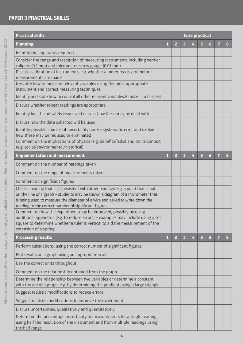
Planning 1 2 3 4 5 6 7 8
Identify the apparatus required
Consider the range and resolution of measuring instruments including Vernier calipers (0.1 mm) and micrometer screw gauge (0.01 mm)Discuss calibration of instruments, e.g. whether a meter reads zero before measurements are madeDescribe how to measure relevant variables using the most appropriate instrument and correct measuring techniques
Identify and state how to control all other relevant variables to make it a fair test
Discuss whether repeat readings are appropriate
Identify health and safety issues and discuss how these may be dealt with
Discuss how the data collected will be used
Identify possible sources of uncertainty and/or systematic error and explain how these may be reduced or eliminatedComment on the implications of physics (e.g. benefits/risks) and on its context (e.g. social/environmental/historical)
Implementation and measurement 1 2 3 4 5 6 7 8
Comment on the number of readings taken
Comment on the range of measurements taken
Comment on significant figures
Check a reading that is inconsistent with other readings, e.g. a point that is not on the line of a graph – students may be shown a diagram of a micrometer that is being used to measure the diameter of a wire and asked to write down the reading to the correct number of significant figuresComment on how the experiment may be improved, possibly by using additional apparatus (e.g. to reduce errors) – examples may include using a set square to determine whether a ruler is vertical to aid the measurement of the extension of a spring
Processing results 1 2 3 4 5 6 7 8
Perform calculations, using the correct number of significant figures
Plot results on a graph using an appropriate scale
Use the correct units throughout
Comment on the relationship obtained from the graph
Determine the relationship between two variables or determine a constant with the aid of a graph, e.g. by determining the gradient using a large triangle
Suggest realistic modifications to reduce errors
Suggest realistic modifications to improve the experiment
Discuss uncertainties, qualitatively and quantitatively
Determine the percentage uncertainty in measurements for a single reading using half the resolution of the instrument and from multiple readings using the half range
M01-iASAL_PHYS_LAB_44754_001-080.indd 4 21/05/2018 15:11
Unc
orre
cted
pro
of, a
ll co
nten
t sub
ject
to c
hang
e at
pub
lishe
r dis
cret
ion.
Not
for r
esal
e, c
ircul
atio
n or
dis
tribu
tion
in w
hole
or i
n pa
rt. ©
Pea
rson
201
8

5
X.X.XX
SPECIFICATIONREFERENCE
CORE PRACTICAL XX: X
Practical skills
Planning 9 10 11 12 13 14 15 16
Identify the most appropriate apparatus, giving details. These may include the range and resolution of instruments and/or relevant dimensions of apparatus (e.g. the length of string used for a pendulum)
Discuss calibration of instruments, e.g. whether a meter reads zero before measurements are made
Describe how to measure relevant variables using the most appropriate instrument(s) and techniques
Identify and state how to control all other relevant variables to make it a fair test
Discuss whether repeat readings are appropriate
Identify health and safety issues and discuss how these may be dealt with
Discuss how the data collected will be used.
Analysis 9 10 11 12 13 14 15 16
Comment on how the experiment could have been improved, possibly by using additional apparatus (e.g. to reduce errors) – examples may include using set squares to measure the diameter of a cylinder and using a marker for timing oscillations
Comment on the number of readings taken
Comment on the range of measurements taken
Comment on significant figures – you may be required to identify and/or round up any incorrect figures in a table of results
Identify and/or amend units that are incorrect
Identify and check a reading that is inconsistent with other readings, e.g. a point that is not on the line of a graph.
Perform calculations, using the correct number of significant figures
Plot results on a graph using an appropriate scale and units – the graph could be logarithmic in nature
Use the correct units throughout
Comment on the trend/pattern obtained
Determine the relationship between two variables or determine a constant with the aid of the graph, e.g. by determining the gradient using a large triangle
Use the terms precision, accuracy and sensitivity appropriately
Suggest realistic modifications to reduce errors
Suggest realistic modifications to improve the experiment
Discuss uncertainties qualitatively and quantitatively
Compound percentage uncertainties correctly
Determine the percentage uncertainty in measurements for a single reading using half the resolution of the instrument and from multiple readings using the half range.
PAPER 6 PRACTICAL SKILLS
M01-iASAL_PHYS_LAB_44754_001-080.indd 5 21/05/2018 15:11
Unc
orre
cted
pro
of, a
ll co
nten
t sub
ject
to c
hang
e at
pub
lishe
r dis
cret
ion.
Not
for r
esal
e, c
ircul
atio
n or
dis
tribu
tion
in w
hole
or i
n pa
rt. ©
Pea
rson
201
8

X.X.XX
SPECIFICATIONREFERENCE
CORE PRACTICAL XX: X
6
Procedure
1 Drop the object from rest and record the time taken, t, for:
(a) the sphere to fall through the trap door
(b) the dowel to pass through the light gate.
2 Repeat step 1 twice more and calculate the mean value of t for each method.
3 Measure and record the height, h, fallen by the object.
4 Vary the height and repeat steps 1–3. You should take readings at at least six different heights.
5 Use half the range in your readings for t as the uncertainty in t. Calculate the percentage uncertainty in t.
6 For method (b), you should measure the length of the dowel.
Learning tips
● Make sure that points plotted on a graph take up more than half of the available space on each scale. You do not always need to include the origin.
● Keep scales simple: one large square as 5, 10 or 20 is ideal. A scale where one large square represents 3 or 7 units (or similar) is very difficult to plot and can often lead to errors.
● Always consider whether the graph line should go through the origin.
● Straight lines should be drawn with the aid of a rule long enough to cover the full length of the line.
● Since the object is falling at constant acceleration, use the appropriate kinematics equation:
(a) s = ut + 1 __ 2
a t 2 where u = 0, a = g, and s = h
This can be rearranged to: t2 = 2h ___ g
Comparison with y = mx + c shows that plotting t2 against h
should give a straight line passing through the origin with gradient 2 __ g .
(b) v2 = u2 + 2as where u = 0, a = g, and s is h
Therefore: v2 = 2gh
Comparison with y = mx + c shows that plotting v2 against h should give a straight line passing through the origin with gradient 2g.
Objectives
● To measure the acceleration due to gravity, g, of an object falling freely and to consider the following alternative methods:
(a) object falling through a trap door
(b) object falling through a light gate
Equipment
● metre rule or tape measure with millimetre resolution
For (a):
● steel sphere
● electronic timer
● electromagnet to retain steel sphere
● trap door switch
● clamp and stand
● low voltage power supply
For (b):
● falling object, such as a dowel with 2 cm diameter, 10 cm long
● means to guide dowel through light gate
● light gate and datalogger
! Safety
● Make sure the stand cannot topple over by clamping it securely.
● Keep hands and face away from the falling objects.
● Turn off the electromagnet between ‘drops’ so that it doesn’t overheat and cause burns.
1.3.11
SPECIFICATIONREFERENCE
CORE PRACTICAL 1: DETERMINE THE ACCELERATION OF A FREELY-FALLING OBJECT
M01-iASAL_PHYS_LAB_44754_001-080.indd 6 21/05/2018 15:11
Unc
orre
cted
pro
of, a
ll co
nten
t sub
ject
to c
hang
e at
pub
lishe
r dis
cret
ion.
Not
for r
esal
e, c
ircul
atio
n or
dis
tribu
tion
in w
hole
or i
n pa
rt. ©
Pea
rson
201
8

X.X.XX
SPECIFICATIONREFERENCE
CORE PRACTICAL XX: X
7
Results
1 Use this space to record your results for method (a).
2 Use this space to record your results for method (b). Use your value for the length of the dowel to calculate the mean speed, v, of the dowel as it passes through the light gate.
CORE PRACTICAL 1: DETERMINE THE ACCELERATION OF A FREELY-FALLING OBJECT 1.3.11
SPECIFICATIONREFERENCE
M01-iASAL_PHYS_LAB_44754_001-080.indd 7 21/05/2018 15:11
Unc
orre
cted
pro
of, a
ll co
nten
t sub
ject
to c
hang
e at
pub
lishe
r dis
cret
ion.
Not
for r
esal
e, c
ircul
atio
n or
dis
tribu
tion
in w
hole
or i
n pa
rt. ©
Pea
rson
201
8
CORE PRACTICAL XX: X
8
Analysis of results
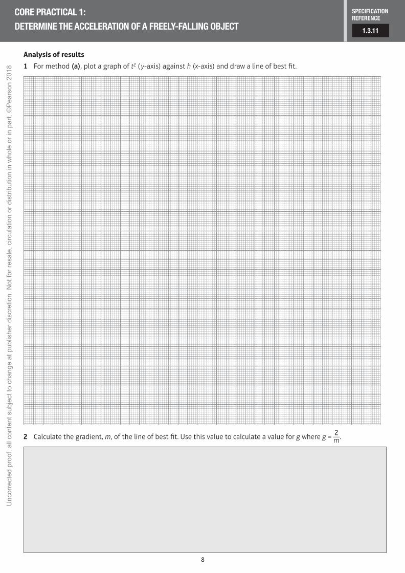
1 For method (a), plot a graph of t2 ( y-axis) against h (x-axis) and draw a line of best fit.
2 Calculate the gradient, m, of the line of best fit. Use this value to calculate a value for g where g = 2 __ m .
CORE PRACTICAL 1: DETERMINE THE ACCELERATION OF A FREELY-FALLING OBJECT 1.3.11
SPECIFICATIONREFERENCE
M01-iASAL_PHYS_LAB_44754_001-080.indd 8 21/05/2018 15:11
Unc
orre
cted
pro
of, a
ll co
nten
t sub
ject
to c
hang
e at
pub
lishe
r dis
cret
ion.
Not
for r
esal
e, c
ircul
atio
n or
dis
tribu
tion
in w
hole
or i
n pa
rt. ©
Pea
rson
201
8
CORE PRACTICAL XX: X
9
3 For method (b), plot a graph of v2 ( y-axis) against h (x-axis) and draw a line of best fit.
4 Calculate the gradient, m, of the line of best fit. Use this value to calculate a value for g, where g = m __ 2
.
CORE PRACTICAL 1: DETERMINE THE ACCELERATION OF A FREELY-FALLING OBJECT 1.3.11
SPECIFICATIONREFERENCE
M01-iASAL_PHYS_LAB_44754_001-080.indd 9 21/05/2018 15:11
Unc
orre
cted
pro
of, a
ll co
nten
t sub
ject
to c
hang
e at
pub
lishe
r dis
cret
ion.
Not
for r
esal
e, c
ircul
atio
n or
dis
tribu
tion
in w
hole
or i
n pa
rt. ©
Pea
rson
201
8

10
CORE PRACTICAL XX: X
5 The percentage uncertainty (%U ) in t2 is twice that in t. Use this to draw error bars onto your graph for method (a) – in the y-direction only. You can use a typical mid-range value to calculate uncertainties – you do not need to work out a separate error bar for each value. Draw a new line of best fit and use this to calculate the %U in your value for g.
6 Calculate the percentage difference (%D) between your value and the accepted value of g (9.81 ms–2) and comment on the accuracy of method (a).
Questions
1 Describe an advantage of using light gates in this experiment.
2 Discuss the effect of air resistance on your value for g.
3 Explain why the graph should be a straight line.
CORE PRACTICAL 1: DETERMINE THE ACCELERATION OF A FREELY-FALLING OBJECT 1.3.11
SPECIFICATIONREFERENCE
M01-iASAL_PHYS_LAB_44754_001-080.indd 10 21/05/2018 15:11
Unc
orre
cted
pro
of, a
ll co
nten
t sub
ject
to c
hang
e at
pub
lishe
r dis
cret
ion.
Not
for r
esal
e, c
ircul
atio
n or
dis
tribu
tion
in w
hole
or i
n pa
rt. ©
Pea
rson
201
8

11
X.X.XX
SPECIFICATIONREFERENCE
CORE PRACTICAL XX: X
Procedure
1 Weigh each ball, measure its radius, r, and hence calculate its density, ρ.
2 Place three rubber bands around the tube. Position the highest band at a level below the surface of the washing-up liquid: the ball must be travelling at terminal velocity when it reaches this band. Place the remaining two bands far enough apart to allow you to measure two reasonable time intervals. This will enable you to measure the terminal velocity twice for each falling ball.
3 Release the first ball into the washing-up liquid. Start the timer when the ball passes the highest rubber band. Use the lap timer facility to record the time taken, t1, for the ball to fall to the middle rubber band. Stop the timer when the ball passes the lowest rubber band; this is t2. Adjust the position of the rubber bands if your first test is not suitable.
4 Once you are happy with the position of the rubber bands, measure the distance, d1, between the highest and middle rubber bands. Then, measure the distance, d2, between the highest and lowest bands.
5 Repeat step 3 at least three times for each ball.
Learning tip
● Position your eyes level with the rubber bands when starting and stopping the timer.
● Try to develop a good technique for measuring the time, so you are consistent. For example, if you take your first measurement as the bottom of the ball crosses the top of the band, make sure you take every measurement at this point. You should also measure your distances from this point.
Results (Use this space to record your results.)
Objectives
● To time the fall of a ball through a liquid to determine the viscosity
Equipment
● stop clock or timer
● rubber bands to mark distances
● metre rule
● micrometer screw gauge
● long tube made of transparent material filled with liquid – supported so it stays vertical
● spherical objects of various diameters
● magnet (optional)
! Safety
● Washing-up liquid spills are very slippery and must be cleared up at once. Have paper towels to hand.
● Clear up any liquid spills quickly to avoid slipping.
● If you use mineral oil or motor oil as the liquid avoid skin contact with it and the oily metal balls.
CORE PRACTICAL 2: USE A FALLING-BALL METHOD TO DETERMINE THE VISCOSITY OF A LIQUID 1.4.26
SPECIFICATIONREFERENCE
M01-iASAL_PHYS_LAB_44754_001-080.indd 11 21/05/2018 15:11
Unc
orre
cted
pro
of, a
ll co
nten
t sub
ject
to c
hang
e at
pub
lishe
r dis
cret
ion.
Not
for r
esal
e, c
ircul
atio
n or
dis
tribu
tion
in w
hole
or i
n pa
rt. ©
Pea
rson
201
8

12
CORE PRACTICAL XX: X
Results (continued)
Analysis of results
1 For each diameter, calculate mean values for t1 and t2. Add these values to your results table.
2 Use d1, d2 and the mean values for t1 and t2 to calculate mean values for the terminal velocity of each ball. Add these values to your results table.
3 Use your answers to question 2 to calculate a mean value for the terminal velocity of all the balls.
4 Consider the spread in your repeated readings and use this to estimate the uncertainty in your mean values. This is usually half of the range.
CORE PRACTICAL 2: USE A FALLING-BALL METHOD TO DETERMINE THE VISCOSITY OF A LIQUID 1.4.26
SPECIFICATIONREFERENCE
M01-iASAL_PHYS_LAB_44754_001-080.indd 12 21/05/2018 15:11
Unc
orre
cted
pro
of, a
ll co
nten
t sub
ject
to c
hang
e at
pub
lishe
r dis
cret
ion.
Not
for r
esal
e, c
ircul
atio
n or
dis
tribu
tion
in w
hole
or i
n pa
rt. ©
Pea
rson
201
8

13
CORE PRACTICAL XX: X
Questions
1 Explain why you would not use light gates to measure the time.
2 Sometimes the balls fall close to the wall. Comment on the effect this will have on the measurements.
3 Use your answer to question 4 above to estimate the uncertainty in your value for the viscosity of the washing-up liquid.
CORE PRACTICAL 2: USE A FALLING-BALL METHOD TO DETERMINE THE VISCOSITY OF A LIQUID 1.4.26
SPECIFICATIONREFERENCE
M01-iASAL_PHYS_LAB_44754_001-080.indd 13 21/05/2018 15:11
Unc
orre
cted
pro
of, a
ll co
nten
t sub
ject
to c
hang
e at
pub
lishe
r dis
cret
ion.
Not
for r
esal
e, c
ircul
atio
n or
dis
tribu
tion
in w
hole
or i
n pa
rt. ©
Pea
rson
201
8

14
X.X.XX
SPECIFICATIONREFERENCE
CORE PRACTICAL XX: X
Procedure
1 Fix the bench pulley at the end of the bench. Trap one end of the wire between the two wooden blocks and secure the blocks to the bench approximately 3 m from the pulley. Lay out the wire so that it passes over the pulley and attach the slotted mass hanger to the end. Measure the diameter, d, of the wire.
2 Lay the metre rule under the wire near the pulley and attach the sticky label to act as a length marker. Judge the length by looking vertically down, over the edge of the paper, at the scale of the metre rule. The set square will help you to do this accurately.
3 Measure the length of wire, L, from the wooden blocks to the edge of the paper.
4 Add a mass to the hanger and record the position of the marker against the metre rule. Calculate the extension, x.
5 Repeat step 4, adding one mass at a time and recording the extension for each mass.
Learning tips
● You might notice significant creep occurring at higher loads. This indicates that the elastic limit of the wire has been exceeded. It is important to use a long length of wire, as the extension will only be small before creep sets in.
● If you use weights of 0.5 N, you will be able to take more readings before the elastic limit is exceeded.
Objectives
● To take measurements of a long wire to determine the Young modulus for copper
Equipment
● metre rule
● micrometer screw gauge
● small piece of sticky label or similar, to mark position on wire
● 90° set square
● 3.1 m length of 36 swg copper wire
● two wooden blocks and clamp to secure one end of the wire
● bench pulley
● slotted masses up to 600 g and hanger
! Safety
● The wire will be about 2 m long and will require a high secure fixing point.
● Wear eye protection when loading the wire in case it snaps.
● Put a catch box filled with crumpled paper or bubbled plastic below the hanging masses to keep your feet out of the drop zone.
● Do not exceed the maximum load as advised by your teacher.
CORE PRACTICAL 3: DETERMINE THE YOUNG MODULUS OF A MATERIAL 1.4.31
SPECIFICATIONREFERENCE
M01-iASAL_PHYS_LAB_44754_001-080.indd 14 21/05/2018 15:11
Unc
orre
cted
pro
of, a
ll co
nten
t sub
ject
to c
hang
e at
pub
lishe
r dis
cret
ion.
Not
for r
esal
e, c
ircul
atio
n or
dis
tribu
tion
in w
hole
or i
n pa
rt. ©
Pea
rson
201
8

15
CORE PRACTICAL XX: X
Results (Use this space to record your results.)
CORE PRACTICAL 3: DETERMINE THE YOUNG MODULUS OF A MATERIAL 1.4.31
SPECIFICATIONREFERENCE
M01-iASAL_PHYS_LAB_44754_001-080.indd 15 21/05/2018 15:11
Unc
orre
cted
pro
of, a
ll co
nten
t sub
ject
to c
hang
e at
pub
lishe
r dis
cret
ion.
Not
for r
esal
e, c
ircul
atio
n or
dis
tribu
tion
in w
hole
or i
n pa
rt. ©
Pea
rson
201
8

16
CORE PRACTICAL XX: X
Analysis of results
1 Plot a graph of mass added against extension.
2 Measure the gradient of the straight portion of the graph and use this to calculate the Young modulus for the copper.
CORE PRACTICAL 3: DETERMINE THE YOUNG MODULUS OF A MATERIAL 1.4.31
SPECIFICATIONREFERENCE
M01-iASAL_PHYS_LAB_44754_001-080.indd 16 21/05/2018 15:11
Unc
orre
cted
pro
of, a
ll co
nten
t sub
ject
to c
hang
e at
pub
lishe
r dis
cret
ion.
Not
for r
esal
e, c
ircul
atio
n or
dis
tribu
tion
in w
hole
or i
n pa
rt. ©
Pea
rson
201
8
17
CORE PRACTICAL XX: X
Questions
1 Explain why a long wire is most suitable for this experiment.
2 Describe a good technique for measuring the diameter of the wire.
3 Explain why a value with two significant figures is appropriate for the Young modulus of the wire.
4 Research a value for the Young modulus of copper and comment on your results, using an appropriate format to cite your research.
CORE PRACTICAL 3: DETERMINE THE YOUNG MODULUS OF A MATERIAL 1.4.31
SPECIFICATIONREFERENCE
M01-iASAL_PHYS_LAB_44754_001-080.indd 17 21/05/2018 15:11
Unc
orre
cted
pro
of, a
ll co
nten
t sub
ject
to c
hang
e at
pub
lishe
r dis
cret
ion.
Not
for r
esal
e, c
ircul
atio
n or
dis
tribu
tion
in w
hole
or i
n pa
rt. ©
Pea
rson
201
8
18
X.X.XX
SPECIFICATIONREFERENCE
CORE PRACTICAL XX: X
Procedure
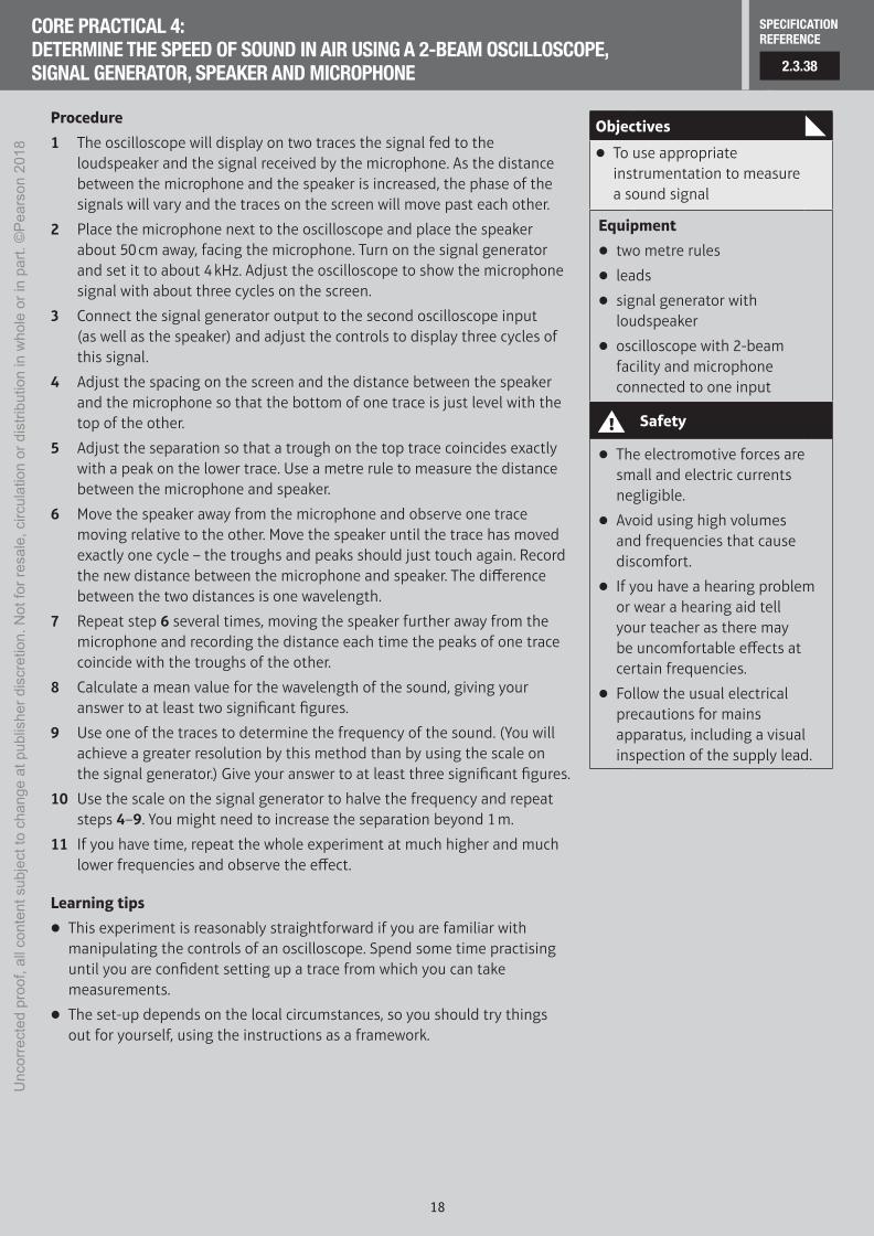
1 The oscilloscope will display on two traces the signal fed to the loudspeaker and the signal received by the microphone. As the distance between the microphone and the speaker is increased, the phase of the signals will vary and the traces on the screen will move past each other.
2 Place the microphone next to the oscilloscope and place the speaker about 50 cm away, facing the microphone. Turn on the signal generator and set it to about 4 kHz. Adjust the oscilloscope to show the microphone signal with about three cycles on the screen.
3 Connect the signal generator output to the second oscilloscope input (as well as the speaker) and adjust the controls to display three cycles of this signal.
4 Adjust the spacing on the screen and the distance between the speaker and the microphone so that the bottom of one trace is just level with the top of the other.
5 Adjust the separation so that a trough on the top trace coincides exactly with a peak on the lower trace. Use a metre rule to measure the distance between the microphone and speaker.
6 Move the speaker away from the microphone and observe one trace moving relative to the other. Move the speaker until the trace has moved exactly one cycle – the troughs and peaks should just touch again. Record the new distance between the microphone and speaker. The difference between the two distances is one wavelength.
7 Repeat step 6 several times, moving the speaker further away from the microphone and recording the distance each time the peaks of one trace coincide with the troughs of the other.
8 Calculate a mean value for the wavelength of the sound, giving your answer to at least two significant figures.
9 Use one of the traces to determine the frequency of the sound. (You will achieve a greater resolution by this method than by using the scale on the signal generator.) Give your answer to at least three significant figures.
10 Use the scale on the signal generator to halve the frequency and repeat steps 4–9. You might need to increase the separation beyond 1 m.
11 If you have time, repeat the whole experiment at much higher and much lower frequencies and observe the effect.
Learning tips
● This experiment is reasonably straightforward if you are familiar with manipulating the controls of an oscilloscope. Spend some time practising until you are confident setting up a trace from which you can take measurements.
● The set-up depends on the local circumstances, so you should try things out for yourself, using the instructions as a framework.
Objectives
● To use appropriate instrumentation to measure a sound signal
Equipment
● two metre rules
● leads
● signal generator with loudspeaker
● oscilloscope with 2-beam facility and microphone connected to one input
! Safety
● The electromotive forces are small and electric currents negligible.
● Avoid using high volumes and frequencies that cause discomfort.
● If you have a hearing problem or wear a hearing aid tell your teacher as there may be uncomfortable effects at certain frequencies.
● Follow the usual electrical precautions for mains apparatus, including a visual inspection of the supply lead.
CORE PRACTICAL 4: DETERMINE THE SPEED OF SOUND IN AIR USING A 2-BEAM OSCILLOSCOPE, SIGNAL GENERATOR, SPEAKER AND MICROPHONE 2.3.38
SPECIFICATIONREFERENCE
M01-iASAL_PHYS_LAB_44754_001-080.indd 18 21/05/2018 15:11
Unc
orre
cted
pro
of, a
ll co
nten
t sub
ject
to c
hang
e at
pub
lishe
r dis
cret
ion.
Not
for r
esal
e, c
ircul
atio
n or
dis
tribu
tion
in w
hole
or i
n pa
rt. ©
Pea
rson
201
8

19
CORE PRACTICAL XX: X
Results (Use this space to record your results.)
Analysis of results
1 Multiply your values for wavelength and frequency to obtain a value for the speed of sound for each of the frequencies used. Hence, find a mean value and percentage difference for the speed of sound.
2 Estimate the uncertainty in your mean value for the wavelength of the sound (calculated in step 8).
3 Estimate the uncertainty in your measurement of the frequency of the sound (calculated in step 9).
4 Use the uncertainties from your measurements to calculate the percentage uncertainty in your individual values for the speed of sound.
CORE PRACTICAL 4: DETERMINE THE SPEED OF SOUND IN AIR USING A 2-BEAM OSCILLOSCOPE, SIGNAL GENERATOR, SPEAKER AND MICROPHONE 2.3.38
SPECIFICATIONREFERENCE
M01-iASAL_PHYS_LAB_44754_001-080.indd 19 21/05/2018 15:11
Unc
orre
cted
pro
of, a
ll co
nten
t sub
ject
to c
hang
e at
pub
lishe
r dis
cret
ion.
Not
for r
esal
e, c
ircul
atio
n or
dis
tribu
tion
in w
hole
or i
n pa
rt. ©
Pea
rson
201
8

20
CORE PRACTICAL XX: X
Questions
1 Comment on the sources of uncertainty in this investigation.
2 Compare your percentage difference and your percentage uncertainties, and comment on your results.
3 When the traces have moved past each other by one full cycle, the speaker has moved one wavelength. Explain this.
4 Explain why 4 kHz is a suitable frequency for this experiment.
CORE PRACTICAL 4: DETERMINE THE SPEED OF SOUND IN AIR USING A 2-BEAM OSCILLOSCOPE, SIGNAL GENERATOR, SPEAKER AND MICROPHONE 2.3.38
SPECIFICATIONREFERENCE
M01-iASAL_PHYS_LAB_44754_001-080.indd 20 21/05/2018 15:11
Unc
orre
cted
pro
of, a
ll co
nten
t sub
ject
to c
hang
e at
pub
lishe
r dis
cret
ion.
Not
for r
esal
e, c
ircul
atio
n or
dis
tribu
tion
in w
hole
or i
n pa
rt. ©
Pea
rson
201
8

21
X.X.XX
SPECIFICATIONREFERENCE
CORE PRACTICAL XX: X
Procedure
1 Attach one end of the ‘string’ to the vibration transducer. Pass the other end over the bench pulley and attach the mass hanger.
2 Add masses until the total mass is 100 g.
3 Turn on the signal generator to set the rubber oscillating. Vary the oscillating length by moving the vibration generator until resonance is observed.
Plan
In this investigation, you will be observing standing waves. These can occur at a variety of resonant frequencies. You will investigate the effect of the factors affecting these frequencies.
You might use a cathode ray oscilloscope to determine the exact frequency of the vibration generator.
Plan which variables you will test in this investigation and how you will carry it out. Your teacher will help you with the details if necessary.
Use this space to record your plan.
Learning tip
● Your measurements will have greater resolution if you measure as large a length as possible, or as many half-wavelengths as possible.
Objectives
● To carry out an investigation into standing waves
● To develop the skills to carry out further investigations
Equipment
● bench pulley
● slotted masses and hanger
● metre rule
● 2 m length of rubber ‘string’
● vibration generator connected to a signal generator
! Safety
● There are no hazards associated with this experiment if rubber is used as the medium.
● If using metal wire, safety spectacles should be worn.
● Follow the usual electrical precautions for mains apparatus, including a visual inspection of the supply lead.
CORE PRACTICAL 5: INVESTIGATE THE EFFECTS OF LENGTH, TENSION AND MASS PER UNIT LENGTH ON THE FREQUENCY OF A VIBRATING STRING OR WIRE 2.3.43
SPECIFICATIONREFERENCE
M01-iASAL_PHYS_LAB_44754_001-080.indd 21 21/05/2018 15:11
Unc
orre
cted
pro
of, a
ll co
nten
t sub
ject
to c
hang
e at
pub
lishe
r dis
cret
ion.
Not
for r
esal
e, c
ircul
atio
n or
dis
tribu
tion
in w
hole
or i
n pa
rt. ©
Pea
rson
201
8

22
CORE PRACTICAL XX: X
Results
1 Use this space to record your results.
2 Assess the uncertainties in your measurements and comment on whether they affect the reproducibility of your findings.
CORE PRACTICAL 5: INVESTIGATE THE EFFECTS OF LENGTH, TENSION AND MASS PER UNIT LENGTH ON THE FREQUENCY OF A VIBRATING STRING OR WIRE 2.3.43
SPECIFICATIONREFERENCE
M01-iASAL_PHYS_LAB_44754_001-080.indd 22 21/05/2018 15:11
Unc
orre
cted
pro
of, a
ll co
nten
t sub
ject
to c
hang
e at
pub
lishe
r dis
cret
ion.
Not
for r
esal
e, c
ircul
atio
n or
dis
tribu
tion
in w
hole
or i
n pa
rt. ©
Pea
rson
201
8
23
CORE PRACTICAL XX: X
Analysis of results
Produce a graph of your results to show the relationships between the variables you identified and measured.
CORE PRACTICAL 5: INVESTIGATE THE EFFECTS OF LENGTH, TENSION AND MASS PER UNIT LENGTH ON THE FREQUENCY OF A VIBRATING STRING OR WIRE 2.3.43
SPECIFICATIONREFERENCE
M01-iASAL_PHYS_LAB_44754_001-080.indd 23 21/05/2018 15:11
Unc
orre
cted
pro
of, a
ll co
nten
t sub
ject
to c
hang
e at
pub
lishe
r dis
cret
ion.
Not
for r
esal
e, c
ircul
atio
n or
dis
tribu
tion
in w
hole
or i
n pa
rt. ©
Pea
rson
201
8

24
CORE PRACTICAL XX: X
Questions
1 Identify the major sources of uncertainty in your work.
2 Explain why you chose the variables you did.
3 Describe what you found difficult to get right and how you did get it right.
4 Research how a standing wave can be set up and used to determine a value for the speed of electromagnetic radiation. Use an appropriate format to cite any sources you use in your research.
CORE PRACTICAL 5: INVESTIGATE THE EFFECTS OF LENGTH, TENSION AND MASS PER UNIT LENGTH ON THE FREQUENCY OF A VIBRATING STRING OR WIRE 2.3.43
SPECIFICATIONREFERENCE
M01-iASAL_PHYS_LAB_44754_001-080.indd 24 21/05/2018 15:11
Unc
orre
cted
pro
of, a
ll co
nten
t sub
ject
to c
hang
e at
pub
lishe
r dis
cret
ion.
Not
for r
esal
e, c
ircul
atio
n or
dis
tribu
tion
in w
hole
or i
n pa
rt. ©
Pea
rson
201
8
25
X.X.XX
SPECIFICATIONREFERENCE
CORE PRACTICAL XX: X
Procedure
1 Place the laser approximately 4 m away from a large wall and place the diffraction grating in front of it. Position the laser so that the beam will pass through the grating at normal incidence and meet the wall perpendicularly.
2 Measure the distance, D, between the grating and the wall.
3 Turn on the laser and identify the zero order maximum (straight through). Measure the distance, s, from the zero order maximum to the first-order maxima on either side. Calculate the mean of these two values. (Remember, the first order is the maximum produced according to n = 1 in the equation nλ = d sin θ.)
4 Measure s for increasing orders, calculating a mean value each time.
5 Repeat steps 1–4 using a diffraction grating with a different number of slits/mm.
Learning tip
● Make sure that the laser hits the wall at right angles.
Results (Use this space to record your results.)
Objectives
● To make measurements of laser light passing through a diffraction grating to determine the wavelength of the light
Equipment
● source of laser light
● diffraction grating, supported at the same height as the laser beam
● metre rule
! Safety
● The laser used should be IEC Class 1 or Class 2.
● The laser should be set up, clamped and used so that the beam cannot reach the eyes either directly or by reflection from a shiny surface.
● Lasers with a higher classification should not be used in school.
● Laser goggles are of no use with Class 1 or 2 because the beam cannot be seen when they are worn.
CORE PRACTICAL 6: DETERMINE THE WAVELENGTH OF LIGHT FROM A LASER OR OTHER LIGHT SOURCE USING A DIFFRACTION GRATING 2.3.52
SPECIFICATIONREFERENCE
M01-iASAL_PHYS_LAB_44754_001-080.indd 25 21/05/2018 15:11
Unc
orre
cted
pro
of, a
ll co
nten
t sub
ject
to c
hang
e at
pub
lishe
r dis
cret
ion.
Not
for r
esal
e, c
ircul
atio
n or
dis
tribu
tion
in w
hole
or i
n pa
rt. ©
Pea
rson
201
8

26
CORE PRACTICAL XX: X
Results (continued)
Analysis of results
1 Since the angle is not small, you will need to calculate θ from your measurements of s and D. Calculate a mean θ value for each order.
2 Calculate a mean value for the wavelength of the laser light and compare this value with the accepted wavelength for a standard school red laser (635 nm).
CORE PRACTICAL 6: DETERMINE THE WAVELENGTH OF LIGHT FROM A LASER OR OTHER LIGHT SOURCE USING A DIFFRACTION GRATING 2.3.52
SPECIFICATIONREFERENCE
M01-iASAL_PHYS_LAB_44754_001-080.indd 26 21/05/2018 15:11
Unc
orre
cted
pro
of, a
ll co
nten
t sub
ject
to c
hang
e at
pub
lishe
r dis
cret
ion.
Not
for r
esal
e, c
ircul
atio
n or
dis
tribu
tion
in w
hole
or i
n pa
rt. ©
Pea
rson
201
8

27
CORE PRACTICAL XX: X
Questions
1 State the advantages of using laser light in this experiment.
2 Explain why a metre rule is suitable for measuring the distance in this experiment.
3 Describe what the diffraction maxima would look like if a white laser was used (assuming such a thing was possible).
CORE PRACTICAL 6: DETERMINE THE WAVELENGTH OF LIGHT FROM A LASER OR OTHER LIGHT SOURCE USING A DIFFRACTION GRATING 2.3.52
SPECIFICATIONREFERENCE
M01-iASAL_PHYS_LAB_44754_001-080.indd 27 21/05/2018 15:11
Unc
orre
cted
pro
of, a
ll co
nten
t sub
ject
to c
hang
e at
pub
lishe
r dis
cret
ion.
Not
for r
esal
e, c
ircul
atio
n or
dis
tribu
tion
in w
hole
or i
n pa
rt. ©
Pea
rson
201
8
28
X.X.XX
SPECIFICATIONREFERENCE
CORE PRACTICAL XX: X
Procedure
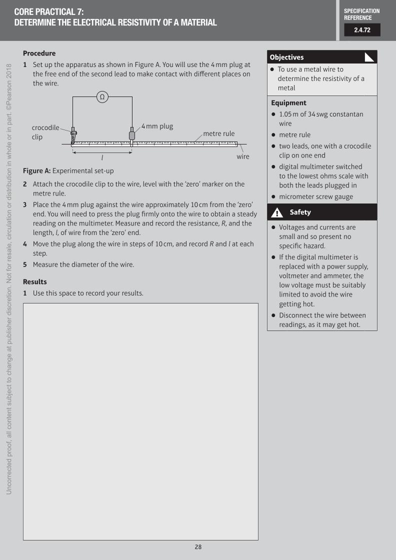
1 Set up the apparatus as shown in Figure A. You will use the 4 mm plug at the free end of the second lead to make contact with different places on the wire.
l
4 mm plugmetre rule
wire
crocodileclip
Ω
Figure A: Experimental set-up
2 Attach the crocodile clip to the wire, level with the ‘zero’ marker on the metre rule.
3 Place the 4 mm plug against the wire approximately 10 cm from the ‘zero’ end. You will need to press the plug firmly onto the wire to obtain a steady reading on the multimeter. Measure and record the resistance, R, and the length, l, of wire from the ‘zero’ end.
4 Move the plug along the wire in steps of 10 cm, and record R and l at each step.
5 Measure the diameter of the wire.
Results
1 Use this space to record your results.
Objectives
● To use a metal wire to determine the resistivity of a metal
Equipment
● 1.05 m of 34 swg constantan wire
● metre rule
● two leads, one with a crocodile clip on one end
● digital multimeter switched to the lowest ohms scale with both the leads plugged in
● micrometer screw gauge
! Safety
● Voltages and currents are small and so present no specific hazard.
● If the digital multimeter is replaced with a power supply, voltmeter and ammeter, the low voltage must be suitably limited to avoid the wire getting hot.
● Disconnect the wire between readings, as it may get hot.
CORE PRACTICAL 7: DETERMINE THE ELECTRICAL RESISTIVITY OF A MATERIAL
2.4.72
SPECIFICATIONREFERENCE
M01-iASAL_PHYS_LAB_44754_001-080.indd 28 21/05/2018 15:11
Unc
orre
cted
pro
of, a
ll co
nten
t sub
ject
to c
hang
e at
pub
lishe
r dis
cret
ion.
Not
for r
esal
e, c
ircul
atio
n or
dis
tribu
tion
in w
hole
or i
n pa
rt. ©
Pea
rson
201
8