Embed Size (px)
Citation preview

LONDON’S GLOBAL UNIVERSITY
University College London
Inclusive Design Specification
For Buildings and Infrastructure works
Version: 1.6 Date: 01 May 2015 Status: Draft

1 Revision: 1.6 01/05/15
1. Contents 1. Contents .......................................................................................................................... 1
1. Introduction/Legislation .................................................................................................... 4
2. Internal Environment ........................................................................................................ 8
2.1 General Aims ............................................................................................................... 8
2.2 Emergency Egress ....................................................................................................... 8
2.3 Building Entrances Aims .............................................................................................. 9
2.4 Reception Areas Aims ................................................................................................ 11
3. Vertical Circulation ......................................................................................................... 14
3.1 General – Aims .......................................................................................................... 14
3.2 Gradients and Ramps – Aims .................................................................................... 14
3.3 Steps and Stairs – Aims ............................................................................................. 15
3.4 Handrails – Aims ........................................................................................................ 18
3.5 Lifts – Aims ................................................................................................................. 19
4. Horizontal Circulation ..................................................................................................... 21
4.1 General Aims ............................................................................................................. 21
4.2 Circulation Routes – Aims .......................................................................................... 21
4.3 Lobbies ....................................................................................................................... 22
4.4 Doors .......................................................................................................................... 23
5. Finishes ......................................................................................................................... 25
5.1 General Aims ............................................................................................................. 25
5.2 Walking Surfaces ....................................................................................................... 25
5.3 Signage and Wayfinding ............................................................................................ 26
5.4 Lighting - Aims ........................................................................................................... 27
5.5 Acoustics and Communications Systems - Aims ....................................................... 28
5.6 Controls - Aims ........................................................................................................... 29
5.7 Visual Contrast - Aims ................................................................................................ 31
5.8 Glazing - Aims ............................................................................................................ 31
6. Specific Areas ................................................................................................................ 34
6.1 General Aims ............................................................................................................. 34
6.2 Study Areas – Hubs, Classrooms, Common Rooms and Labs – Aims ..................... 34
6.3 Theatres and Audience Seating – Aims ..................................................................... 37
6.4 Display Areas / Cases – Aims .................................................................................... 40
6.5 Libraries – Aims ......................................................................................................... 41
6.6 Sports Buildings ......................................................................................................... 42

2 Revision: 1.6 01/05/15
6.7 Residential Buildings .................................................................................................. 42
6.8 Toilet and Shower Facilities – Aims ........................................................................... 42
6.9 Accessible Toilets – Aims .......................................................................................... 43
6.10 WC Cubicle for Ambulant Disabled People – Aims .................................................... 45
6.11 Enlarged Cubicles – Aims .......................................................................................... 46
6.12 Urinals ........................................................................................................................ 47
6.13 Changing and Shower Facilities – Aims ..................................................................... 47
6.14 Changing Places Facility – Aims ................................................................................ 50
6.15 Families – Aims .......................................................................................................... 51
6.16 Quiet Contemplation Facilities – Aims ....................................................................... 53
7. External Environment .................................................................................................... 54
7.1 General ..................................................................................................................... 54
7.2 Pedestrian Movement – Crossing Points – Aims ................................................... 54
7.3 Pedestrian Routes – Aims ...................................................................................... 59
7.4 Seating and Street Furniture - Aims ....................................................................... 60
7.5 Shared Surfaces - Aims .......................................................................................... 63
7.6 Tactile Paving and Dropped Kerbs – Aims ............................................................. 64
7.7 Relief Facilities for Assistance Dogs – Aims........................................................... 65
7.8 Smoking Shelters - Aims ........................................................................................ 66
7.9 Vehicular Facilities – Drop-off and Pick-up - Aims ................................................. 66
7.10 Car Parking - Aims ................................................................................................. 67
7.11 Cycle Facilities - Aims ............................................................................................ 68

3 Revision: 1.6 01/05/15
Version Control
Date Version Change Reason Author Authorised
28/01/2014 1.1 n/a New
06/05/2014 1.2 Updated with comments SJ
09/07/2014 1.3 Updated for meeting SJ
25/07/2014 1.4 Updated with comments SJ
09/04/2015 1.5 Updated with drawings and comments
SJ
01/05/15 1.6 Repositioning External Environment, updating numbering affected
SJ

4 Revision: 1.6 01/05/15
1. Introduction/Legislation 1.1 Introduction University College London (UCL) has a proud history of being the first university in England to be open to all, irrespective of race or religion, and the first to admit women on an equal basis. As part of the recent UCL 2034 strategy, UCL committed to the creation of ‘an accessible, publicly engaged organisation that fosters a lifelong community’ - open and accessible to all. In this regard, UCL recognises that people are different in their needs and in the way they use the built environment and that these differences should be accommodated through informed and thoughtful design. Our aim is to create and support an inclusive ‘place’ where people feel integrated with the UCL community in such a way that individual choice is respected, and where the diversity of individuals is recognised as a valuable and contributing factor. This document is designed to provide guidance to UCL’s staff, consultants and contractors on the inclusive design standards which UCL seeks to achieve across its estate. This is more than just a statement that Part M of the Building Regulations and relevant British Standards has been complied with. It outlines the general design principles, which UCL would wish to see implemented where reasonably practicable. The content reflects the philosophy and approach to inclusive design that is adopted by UCL Estates and the University’s commitment to take all reasonable and practicable steps to ensure the environment at UCL is both inclusive and accessible.
The principles of our inclusive environment:
Easily used by as many people as possible without undue effort, special treatment or separation.
Able to offer people the freedom to choose how they access and participate equally in all of the College’s activities.
Able to embrace diversity and difference. Able to offer a high quality environment that is safe to use. UCL Estates, through consultation with staff and students, will, wherever it is reasonably practicable, adhere to the principles of inclusive design throughout its building and refurbishment programs; through the services it offers; and through the actions of its staff. The inclusive design standard should be applied at the ‘project brief’ stage as an expression of intent, and expanded as a project develops to encompass planning, design, management and maintenance requirements.

5 Revision: 1.6 01/05/15
Section 2: Context 2.1 Legislative Framework
i. The Equality Act The duties imposed by the Equality Act 2010 require all public sector institutions to become proactive agents of change; this is then a ‘positive duty’ through which UCL must demonstrate how we have ‘built in’ equality at the beginning of processes, rather than making adjustments at the end. ii. Overarching goal.
The Equality Duty seeks to address fundamental human rights and so to achieve equality of opportunity. As a public sector institution we are required to be proactive in eliminating the discrimination which can have a very real impact on the lives of people protected by the Act. It can often be difficult for persons without experience of a ‘protected characteristic’ to fully understand the exclusion, labelling and social disadvantage experienced by many disabled people. ‘At present disabled people do not have the same opportunities or choices as non disabled people. Nor do they enjoy equal respect or full inclusion in society on an equal basis. The poverty, disadvantage and social exclusion experienced by many disabled people is not the inevitable result of their impairments or medical conditions, but rather stems from attitudinal and environmental barriers. This is known as ‘the social model of disability’, and provides a basis for the successful implementation of the duty to promote disability equality.’
(DRC Code of Practice 2005) When buildings, services and employment practices are designed in a way that fail to take into account the particular circumstances of disabled people, this excludes and disadvantages them. The same applies when budgets are set for a programme without adequately considering the additional needs of disabled people. iii. How will it operate?
The duty requires that the University shall, in carrying out its functions, have due regard to the need to: • Promote equality of opportunity between disabled persons and other persons. • Eliminate discrimination that is unlawful under the Act. • Eliminate harassment. • Promote positive attitudes. • Encourage participation in public life. • Take steps to take account of a persons’ protected status, even where that involves treating them more favourably than other persons. As we adapt to this role it is no longer sufficient to simply rely on ‘reasonable adjustment’ of facilities and services as part of new-builds and projects. We will assess policies, procedures, planning and decisions such that they demonstrate an inclusive approach from the outset. The General Duty requires UCL not only to have due regard to equality when making decisions about the future; but also to take action to tackle the consequences of decisions in the past which failed to give due regard to equality. This is best approached by consultation and analysis to work towards closing any gaps in service, so
6 Revision: 1.6 01/05/15
that, for example, disabled and non-disabled people express the same level of satisfaction with their accommodation, or obtain a more equal pattern of educational achievement. The Duty therefore places a continuing obligation on ‘authorities’ to prioritise for review those aspects of their functions which have most relevance to disabled people. Through this process UCL Estates will make a real and positive change to our community, promoting full access to opportunities and choices and avoiding making people feel segregated or marginalized. One in four of the population has a disability and thus a significant section of the UCL community is ‘disabled’. The duty will enable UCL to demonstrate its commitment to the promotion of equality and to help widen participation and retention. Section 3: How to use the standards 3.1 What projects do these standards apply to? The UCL inclusive design standards are applicable to all projects that UCL Estates is responsible for conceiving and delivering. In some exceptional circumstances, more appropriate guidance may apply to particular types of buildings and facilities, examples include: Utility buildings with no public access (eg. Energy centres, sub-stations, etc). Plant rooms, control rooms, utility tunnels. Other maintenance related structures. In such cases, it is recommended that the project teams seek specialist advice and refer to building regulations and health and safety authorities for advice and guidance. 3.2 Who should use the guidance? The UCL inclusive design standards are aimed at everyone engaged in the delivery of UCL projects, including Departmental sponsors, designers, project managers, engineers, access consultants and cost consultants. 3.3. Design management procedures The UCL Estates Leadership Team is accountable and responsible for the implementation of these design standards. It requires all UCL UPO’s to ensure that efforts are made to embed the standards within their projects. UCL Estates has established a rigorous design management and monitoring process (referred to as the Portfolio Services) aimed at ensuring the highest standards of design and delivery across its programmes of work. The procedures are intended to provide a framework for designers and contractors to explain the choices that they make and for UCL to make informed decisions. From the outset, the design brief for each project will set out a broad outline of the inclusive design requirements. Project teams must be issued with the UCL inclusive design standards. When evaluating tender submissions for new designers and contractor, project teams should specifically seek to test bidders understanding of the inclusive design principles.

7 Revision: 1.6 01/05/15
Inclusive design will be specifically assessed by the UCL stage gate review process – a process structured around the RIBA and ICE design stages. It is proposed that all design reports submitted for stage gate review must contain a section on inclusive design including reference to compliance with UCL’s inclusive design standards. UCL may choose to employ specialist access consultants to review design proposals and monitor compliance through the project lifecycle.

8 Revision: 1.6 01/05/15
2. Internal Environment
2.1 General Aims Movement within buildings is as important as external environments, and where possible, should be accessible and barrier-free.
Changes in level often cause problems for many people. Where possible, changes in level should be gradual over a shallow gradient. Where steps or stairs are necessary, a step free alternative should also be included within the same location. Circulation routes should have clear lines of sight to reduce people’s dependence on signage and auditory information. For guidance regarding vertical and horizontal movement through buildings refer to Sections 3 and 4 respectively.
Provisions – Internal Environment General Wherever possible, the number of obstacles protruding into, or located within the
walking area should be kept to a minimum
If provided, they should have adequate visual contrast with the critical surface they will be viewed against
2.2 Emergency Egress This Section should be read in conjunction with the emergency arrangements and strategies already in place at UCL regarding emergency situations. Such as the creation of Personal Emergency Evacuation Plans (PEEPs) as well as specific considerations when designing for disabled people and the need for environments to be designed with these in mind.
The following provisions are some specific considerations that should be included in the design. Strategies should be discussed with the UCL Fire Safety Manager to ensure a consistent approach and manageable solutions
Provisions – Existing UCL Buildings For existing buildings UCL requires an individual assessment to be undertaken.
Asking the person what they can/cannot do and where they need assistance practically. Any physical changes required to premises and local (department) management controls. These are then set out in a PEEP
UCL will undertake all reasonable adjustments of premises to meet the needs of the individual and or general conditions as far as reasonably practicable
Provisions – Alterations and Refurbishments in Existing UCL Buildings During the design stages of any refurbishment of a UCL building – to introduce
changes and improvements to emergency arrangements for disabled people to be incorporated as far as reasonably practicable

9 Revision: 1.6 01/05/15
Provisions – New Buildings All new buildings to meet both current and additional UCL requirements to
ensure emergency arrangements are practical and appropriate
Provisions – General Consideration of the location and provision of refuges
Provision of progressive horizontal evacuation to another (safer) part of the premises or to safety via an adjoining building
A two way communication device must be provided at all refuge points, which is linked with the UCL Communication Room
Clear signage and wayfinding to be provided
Warning to be provided audibly e.g. voice, and visually e.g. lighting, by means as appropriate for the use and occupancy types – as per UCL Fire Alarm design guidance
Deaf Messaging Systems (DMS) to provide warning to subscribers on their mobile phones
Provisions – Student Halls of Residences (Sleeping Accommodation) Specialist vibrating pillow devices and other addition to be available to assist with
fire alarm activation
Help points and entrance intercom systems are to use ‘Commend Intercom System’ (www.commend.co.uk), which are compatible with UCL Cardex (Gallagher) Access System (details via the UCL Access Systems Manager)
A communication device must be provided at all Accessible WC points, which is linked to the UCL Communication Room
All new buildings must be provided with an evacuation lift
Any refurbishment of existing lifts in UCL premises must consider the provision or converting an existing lift to become an evacuation lift suitable for use by disabled people
Platform lifts may need to be provided with Card Access or free from control depending on locations within the UCL Security boundary
Emergency egress for disabled people and associated arrangements and equipment should be discussed with the UCL Fire Safety Manager in all cases
2.3 Building Entrances Aims People visiting a destination for the first time may not understand the layout of the building. It is important that buildings are easily understandable to ensure smooth crowd flow. Entrances should therefore have a logical relationship within the routes that serve them and be clearly identifiable.

10 Revision: 1.6 01/05/15
Provisions – Building Entrances The entrance should be clearly signposted, both at the entry point and within the
Campus
The entrance door and door furniture to visually contrast with each other and the surroundings
Any structural supports do not cause obstructions or hazards
Clear opening width of at least 1000mm (775mm – existing buildings)
A 1500mm by 1500mm space directly in front of the entrance, clear of door swings
Vision panels to be provided for solid doors or manifestations for glazed doors and panels
Manual doors to have an opening force not more than 30N at the leading edge from 0º (the door in the closed position) to 30º open, and not more than 22.5N at the leading edge from 30º to 60º of the opening cycle
Manual fire doors are exempt from the above point, however, they should be opened with the least possible pressure whilst still providing life safety requirements
Most revolving doors are not accessible and should not be provided
Automated pass doors are to be provided (the type should be determined on a case by case basis in consultation with UCL, considering issues such as security and means of escape)
Automatic sensors to be set to allow enough time for safe entry and exit
Automatic swing doors to have visual and audible warnings
Any manual controls for powered doors to be located at a height between 750mm and 1000mm
Door furniture or controls to be operable with one hand using a closed fist
When open, entrance doors should not project into an access route (where this is absolutely necessary provide barrier protection)
Weather protection to be provided at non-powered entrance doors
A level threshold to be provided, or if unavoidable, an upstand no more than 15mm rise is permitted
Door entry systems to be usable by people who are deaf or hard of hearing as well as those who can’t speak
Two-way communication systems are required at entrances, to allow people to call for assistance (where this links to is to be determined in agreement with UCL)
Any security provisions to be assessed to ensure they are accessible for all to use (e.g. a pass gate would be necessary where access is required through turnstiles or similar)
Finishes to be in accordance with Section 5

11 Revision: 1.6 01/05/15
2.4 Reception Areas Aims The reception area is a vital information point for anyone visiting a building, it needs to be accessible to all.
Provisions – Reception Areas To be easily identifiable from the entrance doors or lobby
Where external noise may be a problem, reception desks are to be located away from the entrance
Reception desks to be accessible by both visitors and users
The approach to a reception desk or counter to be direct and unobstructed, in accordance with Diagram 1
Where practicable, a reception counter/desktop should have a working surface at two heights:
a) between 950mm and 1100mm to accommodate people who are standing (where there is sufficient space for a long counter/desktop, two different heights for standing people can be provided)
b) 760mm to accommodate wheelchair users.
See Diagram 2 for the key dimensions required
A minimum work surface depth of 700mm to be provided between worker and visitor (to avoid excess depths, knee spaces for wheelchair users are not to be arranged directly opposite each other)
The minimum width of low level counter to be 1500mm, where practicable it should be at least 1800mm (width allows space for a companion and/or allows two wheelchair users to sit diagonally opposite each other, where knee recesses are provided)
Where it is desirable for the floor on the worker’s side of the counter to be at a higher level than that of the visitor’s side (e.g. Box Office), and there is sufficient floor space, provided a ramp to allow a wheelchair user to gain access
Where transactions are involved, an upward sloping leading edge to be provided at the front of a counter
A hearing enhancement system to be provided to assist people who are hard of hearing
Security provisions (including turnstiles and pass gates) to be accessible and maintain an accessible and clear access route (this includes use by wheelchair users and ambulant disabled people including people with guide dogs and long canes)
Seating to be suitable for all to use,
The seat height (or compressed cushion height) to be between 450mm and 475mm.

12 Revision: 1.6 01/05/15
Level space for wheelchair users to be provided within waiting areas
All equipment provided for general use, i.e. telephones & internet terminals, to be accessible to disabled people, including those with sensory impairments
Where public telephones are provided at least one telephone in a bank to be accessible to wheelchair users
All telephones to incorporate amplification, inductive couplers and facilities for blind and partially sighted people
At least one textphone facility compatible with the Typetalk relay service to be provided for people who are deaf or hard of hearing
Textphone facilities to be indicated by clear signage
1) (Counter/desktop with min. 500mm deep knee recess)
2) (Counter/desktop without knee recess)
Diagram 1 Space Required when Approaching a Reception Desk

13 Revision: 1.6 01/05/15
Diagram 2 Key Dimensions of Counters / Reception Desks

14 Revision: 1.6 01/05/15
3. Vertical Circulation
3.1 General – Aims It is important that disabled people are able to access all facilities and destinations. Changes in level cause problems for many people, particularly disabled people, with mobility or visual impairments. Where stepped access is provided there should also be a step-free alternative.
3.2 Gradients and Ramps – Aims Gradients throughout the Campus must be kept as shallow as possible. Ramps and graded routes are provided to overcome localised changes in level. Steep ramps are trip and slip hazards, and often require excessive effort for some people to access independently.
Provisions – Gradients and Ramps The gradient of a route is to be as shallow as possible
A gradient of 1:60 or shallower is considered level
Gradients shallower than 1:20 but steeper than 1:60 are considered graded routes
Where ramps are provided they are to be no steeper than 1:20 with a width of at least 1500mm
Level landings to be provided at the head and foot of any graded route or ramp
Level landings are to be at least the width of the ramp and have a length of at least 1.2m
Intermediate level landings to be provided for every 500mm rise of a graded route and at intervals of 10m for 1:20 ramps
Intermediate level landings are to be at least the width of the ramp or graded route, a length of at least 1500mm
Passing places (with dimensions of 1800mm by 1800mm) to be provided at the top, bottom or intermediate landings of ramps where sightlines are obstructed or where there is a change of direction
Curved ramps are more difficult for wheelchair manoeuvring and are to be avoided
Where a ramp exceeds a rise of 300mm, steps are to be provided
Where the rise of a ramped route exceeds 2m a lift is to be provided
Ramp surfaces to contrast with level landings and the surrounding surfaces
A tapping edge to be provided to the sides of ramps (to assist cane users), at a height of 100mm

15 Revision: 1.6 01/05/15
Areas under ramps and graded routes to either have guarding or be closed off to avoid anyone colliding with the underside
Guarding to be either by a protective guardrail and low-level cane detection or a continuous barrier (extending at least 900mm above ground level)
3.3 Steps and Stairs – Aims Stairs restrict movement and speed of movement for a large proportion of people. These people include not only those with mobility impairments but people who may be aged, people with children or people encumbered in some other fashion e.g. people carrying luggage.
Wheelchair users are unable to use steps, while some ambulant disabled people have difficulty using ramps. It is therefore recommended that where steps are necessary, a step-free alternative should also be provided and likewise where ramps are provided steps should be provided. This will ensure suitable access is available for all people.
When considering the number of risers in a flight, designers should weigh up the benefits of minimising the number of risers to create more frequent resting points with the benefits of maximising the number of risers to reduce the number of potential accident areas (moving from a landing to a flight). The former is likely to benefit people with restricted mobility, the latter blind or partially sighted people.
Provisions – Steps and Stairs Stairs are required where there are ramps or lifts
Stairs are not required where the rise of a ramp is less than 300mm
Provide no less than two risers
Stairs to have no more than 12 risers; 16 risers are permitted, only in small premises where the plan area is restricted
Spiral stairs, tapered treads and open risers increase the risk of tripping when using the stair and to be avoided
Where projecting nosings are provided, the overlap is not to exceed 25mm
For safety, stairs are to be designed with a consistent width
Stairs to have a minimum surface width of 1200mm (1000mm between handrails)
Stairs to have landings at the head, foot and between flights with a depth at least equal to the width of the channel of the flight
Have landings with an unobstructed length (clear of door swings) not less than 1200mm, although 1800mm is preferred
Stairs to have uniform risers and treads in consecutive flights
Stair riser heights to be between 150 and 170mm

16 Revision: 1.6 01/05/15
Stair treads to be between 300mm and 450mm
Stairs to have slip resistant treads
Stairs to have visually contrasting nosings at a depth of 55mm across the full width of the step (on both the riser and tread), this is particularly important for partially sighted people
External stairs to have a suitable tactile warning at the top and bottom for blind and partially sighted people, a ribbed corduroy paving strip is required in accordance with Diagram 3
A hazard warning surface is not required for internal stairs (there is no warning surface which is deemed to be safe, not constituting a trip hazard when used alongside flooring surfaces with different frictional resistance characteristics)
Steps and stairs should not be placed directly in line with an access route
Either provide guarding or close off areas under stairs, to avoid anyone colliding with the underside
This to be either by a protective guardrail and low-level cane detection or a continuous barrier (extending at least 900mm above ground level)
Escape stairs to be designed to the same standard as general access stairs, in order that they are suitable for use by ambulant disabled people and blind / partially sighted people in an evacuation

17 Revision: 1.6 01/05/15
Diagram 3 Plan of stairs including ‘Corduroy’ hazard warning

18 Revision: 1.6 01/05/15
Diagram 4 Internal stairs – key dimensions
Note: Maintenance stairs are not required to be accessible for disabled people and should be designed to the parameters set out within BS 5395-3 or BS 4211
3.4 Handrails – Aims Handrails give support to people as they negotiate changes of level. The horizontal extension of a handrail beyond the top and bottom of a stair or ramp allows an individual to steady or brace themselves before ascending or descending. Blind and partially sighted people recognise the change in slope of the handrail and its return into a wall as a signal that they have reached the start or finish of a flight.
Provisions - Handrails Handrails are to be provided for all stepped and ramped access
Handrails to be continuous at each side of steps and ramps, and across intermediate landings
Handrails are not required for graded routes, as it is assumed that the gradients will be shallow enough for people to negotiate without the need for support
Provide handrails at a height of 1000mm centred above the pitch line to the top of the handrail
Handrails to be 1100mm high when acting as a balustrade
A second, lower handrail to be provided at a height of 600mm

19 Revision: 1.6 01/05/15
Handrails to extend 300mm horizontally past the top and bottom of the first and last step, or past the top and bottom of a ramp, before returning to ground/wall/ finishing in a positive end
Handrails should be round with a 40-50mm diameter; or elliptical with 50mm width and 38mm depth. It is intended that UCL will standardise handrails, any provision to be discussed and agreed
Handrails to stand off from any wall/obstacle by between 50 and 60mm
Provide handrails 50mm above any fixing bracket
Handrails are not to project into the minimum clear width of the stair or ramp by more than 100mm
When the width of the stairway is greater than 2000mm, provide additional handrails to create channels of 1000mm (minimum between handrails) and 2000mm (maximum)
Handrails to contrast visually with the surroundings
Handrails are not to be constructed using materials that are highly reflective and where used externally, are not to be cold to the touch e.g. steel
Where used as guarding, the loads are to be in accordance with BS EN 1991-1-1 and PD 6688-1-1
3.5 Lifts – Aims A passenger lift is the most suitable means of vertical access to get to a destination within a suitable timescale and in comfort.
Provisions - Lifts Unless indicated specifically, these requirements are for passenger as well as
platform lifts.
All new buildings must be provided with an evacuation passenger lift
Lift design (including lobby and car size) will be governed by their location within the building
Any refurbishment of existing lifts in UCL premises must consider the provision or converting an existing lift to become an evacuation lift suitable for use by disabled people
Lifts to be located adjacent to other means of vertical circulation
The number of lifts provided and their capacity will need to accommodate the expected people flow
Existing buildings will require a bespoke solution, this to be discussed and agreed with EM & I
New buildings are to have passenger lifts serving all storeys (including roof terraces)
Platform lifts and wheelchair stair lifts are not to be used within new buildings

20 Revision: 1.6 01/05/15
Non-enclosed platform lifts are usually used for shorter vertical travel distances, enclosed platform lifts are usually used for longer vertical travel distances
Platform lifts, where provided, should are to be designed to allow both assisted and unassisted use
Platform lifts may need to be provided with Card Access or free from control depending on locations within the UCL Security boundary
Lifts to have a clear level landing directly in front of the lift of at least 1500mm by 1500mm for manoeuvring and waiting
A covered shelter to be provided at all entrance locations of external lifts
Additional consideration to be given to the material finish of external lifts and how this will be affected by the weather (including consideration of slip resistance, comfort and safety in use)
Lifts to conform to the requirements contained within the BS EN 81 Series
Internal lift requirements to be discussed and agreed with EM & I however consideration of the following are important requirements to note:
Where provided, mirrors are not to cause visual confusion and are to provide views at high and low levels for a wheelchair user to see behind them when reversing
Lift floor coverings shall be slip resistant and contrast visually with landing surfaces
Lift floors are not to be black in colour, as this may be mistaken as an opening, rather than a floor material
Door openings to visually contrast with the surroundings
Lifts to have adequate visual contrast between key surfaces and features
Where manual doors and gates are provided for platform lifts, the maximum opening force requirements for standard doors will apply
Manifestations to be provided for glazed lifts (refer to Section 5.8 for Glazing requirements)
Lighting within the lift car is not to cause glare, reflection, confusing shadows or pools of light and dark

21 Revision: 1.6 01/05/15
4. Horizontal Circulation
4.1 General Aims Horizontal circulation issues take account of all movement throughout any individual level and include doors, corridors or pathways and lobbies.
Clear lines of sight should be maintained to maximise accessibility, reduce confusion, and reduce people’s dependence on signage and auditory information.
Each floor plate should be level; where level changes are unavoidable, both stepped and step-free means of access will be required.
4.2 Circulation Routes – Aims Circulation routes should be planned to minimise travel distances from entrances to study areas and communal spaces, and from these spaces to refuges, evacuation lifts and toilets.
Designs should take account of crowds where the visibility of wheelchair users or people of shorter stature is impeded. It is important to consider the spatial requirements for a wheelchair user to reverse or turn around – if space is confined then this could cause great disruption to people flows and will also cause frustration to disabled people and non-disabled people alike.
Wheelchair users should be able to manoeuvre through circulation routes with minimum effort, the width of corridors is a particularly important consideration.
Provisions – Circulation Routes Main corridors to have a minimum clear width of 1800mm to allow two
wheelchairs to pass one another
Any additions i.e. lockers are not to reduce this clear width
Secondary corridors to have a minimum width of 1200mm with passing places provided (passing places to be at least 1800mm long with an unobstructed width of at least 1800mm)
Passing places to be provided at junctions of corridors or pathways
Corridors and circulation routes are to be unobstructed
See diagram 5 for examples of corridor provision
Rest areas to be located so as not to interfere with the flow of circulation and are to contain seating
A minimum headroom of 2.4m (especially at the rear of seating areas e.g. lecture theatres) to be provided in all areas

22 Revision: 1.6 01/05/15
Diagram 5 – Corridors
4.3 Lobbies Consideration should be given to where lobbies provide access to, their size and how they are used. Each lobby should be designed to accommodate all users and to permit one door to close before the other is opened. Where appropriate, lobbies should allow a wheelchair user to rotate through 180º.
Provisions – Lobbies Lobbies to be designed to Diagram 6

23 Revision: 1.6 01/05/15
Diagram 6 Key dimensions for lobbies with single doors
4.4 Doors Internal doors should maximise accessibility without compromising privacy, safety or security. Each door should provide at least the minimum effective clear door opening appropriate to the width and direction of approach. When providing doors, safety is a fundamental issue that should be considered to ensure no injuries could be caused such as trapping, crushing or shearing (doors are to be reviewed on a case-by-case basis).

24 Revision: 1.6 01/05/15
Doors should be seen against their surroundings and door furniture should also be visible, see Section 5.7 for further information regarding visual contrast.
Provisions – Doors Automatic or power assisted doors are preferred within circulation routes
wherever their installation is possible Revolving doors with adjacent pass doors are not considered inclusive and therefore are not to be used
The number of doors provided are to be kept to a minimum, as they can restrict access
Where provided along corridors, hold open devices are to be used (fire doors to either be kept closed or fitted with automatic releases as appropriate)
Internal doors to have a minimum clear opening width of 1050mm
Double doors to have at least one leaf with the minimum clear opening width (1050mm) (UCL enhanced)
Clear opening widths are measured clear of any door ironmongery and framing
Provide a clear wall space of at least 300mm to the leading edge side of doors
All swing doors to be designed and located so that they can swing to at least 90º
Bi-fold and manual sliding doors are to be avoided
Doors, other than those for accessible toilets, must not open out into corridors
Doors to incorporate visibility glazing from a height of 500mm to1500mm (unless omitted for privacy or security reasons)
The opening force on manually operated doors, when measured at the leading edge of the door, to be not more than 30N from 0° (the door in the closed position) to 30° open, and not more than 22.5N from 30° to 60° of the opening cycle
Where fitted with a latch, the door opening furniture is to be operable with one hand using a closed fist, e.g. a lever handle
The leading edge of any door that is not self-closing, or is likely to be held open, is to contrast visually with the door surfaces and its surroundings
All door opening furniture to contrast visually with the surface of the door and the door frames to contrast visually with the surrounding wall (see Section 5.7 for further information regarding visual contrast)

25 Revision: 1.6 01/05/15
5. Finishes
5.1 General Aims Finishes are an important aspect of a built environment, and can have a positive or negative effect on navigation. Positive effects include the ability for finishes to assist with wayfinding for partially sighted people; negative effects include the creation of hazards to users of the environment, for example, producing slippery walking surfaces, and confusion by glare and reflection.
5.2 Walking Surfaces Walking surfaces should be chosen to ensure that all people can travel horizontally through a site or a building conveniently, safely and without discomfort. Finishes should be carefully considered to ensure that they are not confusing - e.g. striped patterns on floors that could be mistaken for steps.
Provisions – Walking Surfaces Changes in materials to be flush, smooth and firm, removing the risk of tripping.
Surfaces to be hard enough so that wheelchairs and mobility aids (such as long canes and sticks) do not sink into them.
Loose surfaces such as crushed rock, gravel or grit are not suitable
With the exception of tactile paving, undulations in the surface of paving are not to exceed 3mm under a 1m straight edge.
Tactile paving must be provided to indicate the location of hazards on an access route
Matwells or similar to be provided at entrances to aid the removal of moisture and soil upon entry
Glossy or highly polished materials are not to be used as they can cause reflective glare, which can cause confusion, especially for partially sighted people
Bright colours, busy patterns and distracting wall coverings are to be avoided as they can cause confusion
Provide sufficient slip resistance in both wet and dry conditions (pendulum test values to be in accordance with BS 7976-2)
It is important to ensure the slip resistance or grip is not too strong as it can act as a barrier to people who walk with a shuffle (surface micro-roughness measurements to be in accordance with BS 1134-1)
Deep pile carpets or the coir type matting that can sometimes be found within entrances are not suitable within internal environments
Textured paving and coloured edge markings can be used to indicate the presence of hazards and will aid partially sighted people to navigate slopes, steps and pavements

26 Revision: 1.6 01/05/15
5.3 Signage and Wayfinding Signage should be clear, concise and consistent, and suitable for people with visual impairments and learning disabilities, such as dyslexia. Temporary signage is as important as permanent signage, if not more so, changes to a known environment can easily cause confusion if the message is not clear.
In addition to signage, wayfinding is also informed by the built environment itself. Landmark buildings, features and entrances can assist navigation and wayfinding throughout the Campus, aiding legibility and helping people to identify and recognise locations.
Provisions – Signage and Wayfinding To be provided within external and internal environments
Internal signage to be provided in public as well as back of house areas
Provide a directory indicating the accessible route through a building and the core/shared facilities
Easy to see (visual contrast with surroundings), with low glare, and easy to understand (simple, short and to the point)
The height of signage to be carefully considered to accommodate people of varying stature, as well as maintaining visibility should crowds obstruct lower positioned signage
Universally accepted colour coding includes the following:
Blue for mandatory instructions
Green for safety
Yellow for hazard
Red for danger/emergency
The optimum viewing angles for signs mounted on wall or other vertical surfaces are +/- 30 degrees in the vertical plane (from eye level) and up to 20 degrees either side of a 90 degree line to the sign in the horizontal plane.
The text height for safety signs to be in accordance with BS 5499-5
The text height for non-safety signs to be in accordance with Table 1
The background of signage and any symbols or text to contrast visually with each other and with the background it will be seen against, a difference of 70 Light Reflectance Value Points (LRV) is required
Signage that contains pictures will benefit almost everyone within the Campus and can be used independently or alongside text (e.g. the use of arrows for directional signage)
Independent use of pictures only to be considered where confusion will not be possible

27 Revision: 1.6 01/05/15
Where space allows, symbols to be at least 100mm in height
Signs meaning the same thing should always appear the same
Tactile signage to be provided where it will benefit users, e.g. on or beside doors to specific rooms
Provide relevant information (on the internet, literature, etc.) detailing the accessibility of the facility (this may include drawings to indicate the accessible routes, highlighting lifts, accessible toilets and level thresholds)
This to be supplemented by an efficient signage strategy within the facility itself, for assistance throughout the duration of the visit Within public buildings e.g. the theatre, where appropriate, signage within the Campus to include several languages, with information in English provided first and additional languages provided subsequently.
Accessible elements to be identified by the International Symbol of Access (ISA) (diagram contained within Appendix A)
Tactile guide maps are an additional aid for partially sighted people, as well as those with memory or place orientation difficulties (tactile maps assist these people to independently find their way around the built environment)
Viewing distance Type of sign x-height
Long distance Signs seen when approaching a building
150mm min
Medium distance Directional signs 50mm to 100mm
Short distance Room signs 15mm to 25mm
Table 1 Signage Dimensions
5.4 Lighting - Aims Due to changes in seasons, low natural lighting levels can be experienced during early mornings and afternoons within the winter months. Supplementary artificial lighting in these conditions is very important, particularly for visitors, new staff or students who are unfamiliar with the Campus.
People who are deaf or hard of hearing who rely on lip reading for communication, as well as partially sighted people, benefit from areas that are well lit. There are also security benefits, people will not only feel safer, but well lit areas will also aid the use of CCTV cameras.
Important areas where lighting levels should be maintained include main circulation routes, building entrances, areas where it will be necessary for communication or specific information to be read or entered, e.g. by keypad.
28 Revision: 1.6 01/05/15
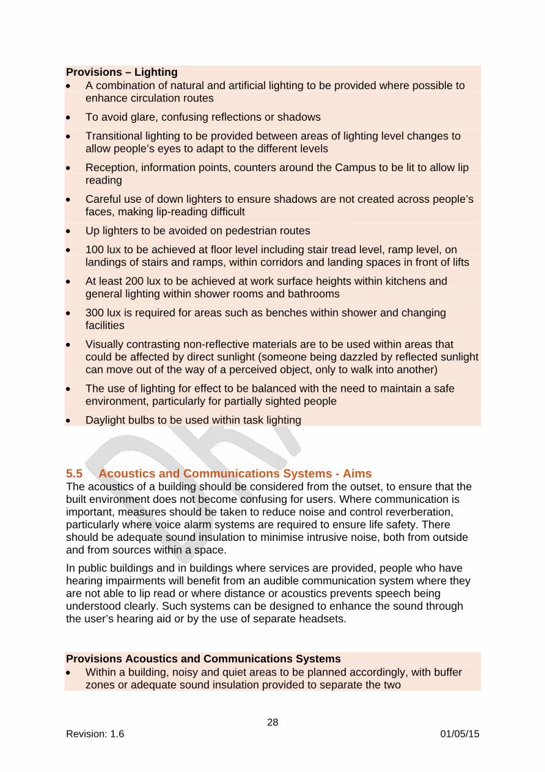
Provisions – Lighting A combination of natural and artificial lighting to be provided where possible to
enhance circulation routes
To avoid glare, confusing reflections or shadows
Transitional lighting to be provided between areas of lighting level changes to allow people’s eyes to adapt to the different levels
Reception, information points, counters around the Campus to be lit to allow lip reading
Careful use of down lighters to ensure shadows are not created across people’s faces, making lip-reading difficult
Up lighters to be avoided on pedestrian routes
100 lux to be achieved at floor level including stair tread level, ramp level, on landings of stairs and ramps, within corridors and landing spaces in front of lifts
At least 200 lux to be achieved at work surface heights within kitchens and general lighting within shower rooms and bathrooms
300 lux is required for areas such as benches within shower and changing facilities
Visually contrasting non-reflective materials are to be used within areas that could be affected by direct sunlight (someone being dazzled by reflected sunlight can move out of the way of a perceived object, only to walk into another)
The use of lighting for effect to be balanced with the need to maintain a safe environment, particularly for partially sighted people
Daylight bulbs to be used within task lighting
5.5 Acoustics and Communications Systems - Aims The acoustics of a building should be considered from the outset, to ensure that the built environment does not become confusing for users. Where communication is important, measures should be taken to reduce noise and control reverberation, particularly where voice alarm systems are required to ensure life safety. There should be adequate sound insulation to minimise intrusive noise, both from outside and from sources within a space.
In public buildings and in buildings where services are provided, people who have hearing impairments will benefit from an audible communication system where they are not able to lip read or where distance or acoustics prevents speech being understood clearly. Such systems can be designed to enhance the sound through the user’s hearing aid or by the use of separate headsets.
Provisions Acoustics and Communications Systems Within a building, noisy and quiet areas to be planned accordingly, with buffer
zones or adequate sound insulation provided to separate the two

29 Revision: 1.6 01/05/15
The excessive use of hard, sound reflecting surfaces to be avoided, where possible, to control reverberation (hard surfaces will reflect sound and create echo and reverberation)
Induction loop hearing enhancement systems to be provided in all reception areas, larger teaching and learning areas, theatres, and other areas where clear communication is required
Hearing enhancement systems may be fixed or portable, and are to be provided with volume controls
The layout and complexity of system used will need to be determined on a case by case basis, depending on the type of building or space and the purpose it serves (induction loops can create overspill into other areas, both adjacently and above or below that require additional components or revised layouts)
All auditory information and systems, including public address (PA) systems, are to be supplemented with visual information. Tactile information, where appropriate, is to be considered.
PA systems for performances and announcements are to be amplified in a form that is suitable for people who are deaf or hard of hearing
Systems to be tested by user trials.
5.6 Controls - Aims Controls such as handles, switches and buttons (for example, for doors, lights, windows, control panels, intercom systems) are all forms of controls that should be suitable for use by both disabled and non-disabled people within the built environment.
Precise movements that are required for systems such as keypads should be designed with keys that can be pressed easily, or where possible, an accessible alternative for people who are unable to use the keypad at all should be provided.
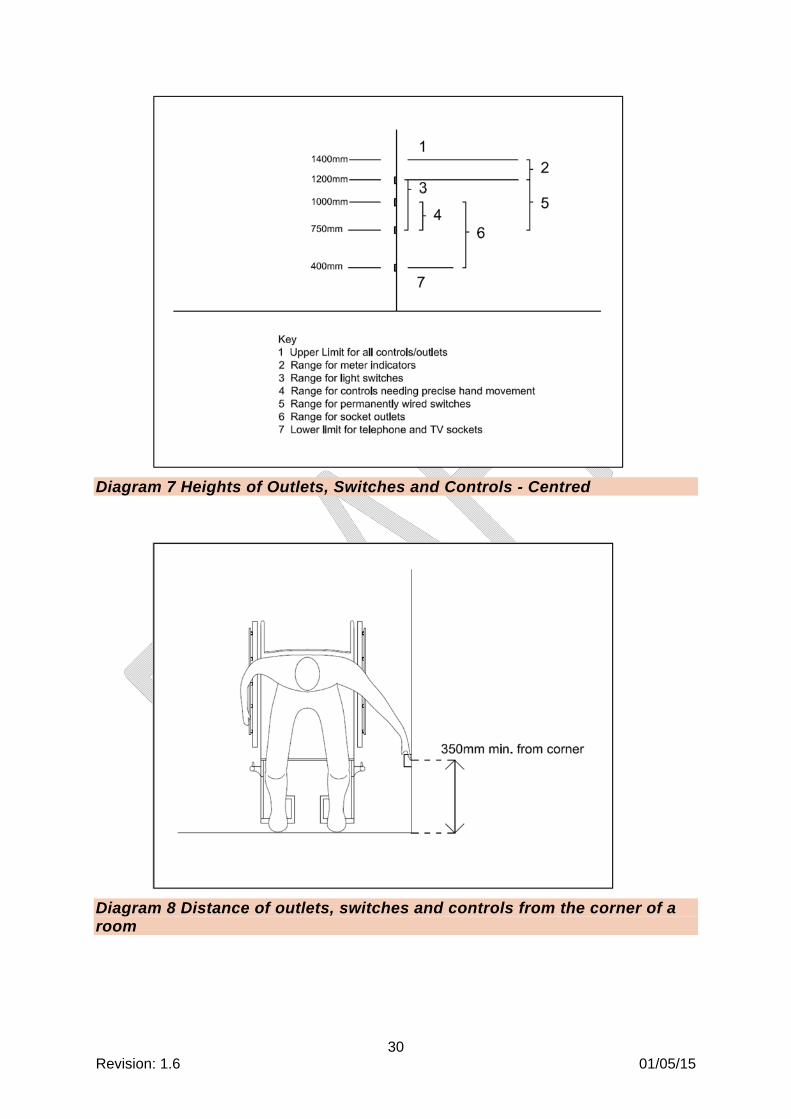
Provisions – Controls Located at an accessible height in accordance with Diagram 7
Located at least 350mm from corners of rooms (as shown in Diagram 8)
To be operable with a closed fist
Distinguishable by touch (for example highlighting the number 5 on a keypad with a raised indicator)
Visual indication of accessible controls (for example, lights around buttons)
Visual information (for example, LED displays at control panels) that is located at an accessible height and whose contrast levels can be controlled / adjusted (where practicable)
30 Revision: 1.6 01/05/15
Diagram 7 Heights of Outlets, Switches and Controls - Centred
Diagram 8 Distance of outlets, switches and controls from the corner of a room

31 Revision: 1.6 01/05/15
5.7 Visual Contrast - Aims Visual contrast of critical surfaces and obstacles makes navigating through a space easier. This may include visual contrast between the ground and building facades, or between freestanding objects (for example columns, sculptures and street furniture) and the background against which they are to be seen.
Colour schemes and finishes should have suitable levels of visual contrast. This enables people, particularly those with visual impairments, to identify the junctions between key surfaces, and to understand the size and boundaries of a space.
Provisions – Visual Contrast Contrast levels to be a minimum of 30 light reflectance value (LRV) points
difference, 70 points difference on signage
Visual contrast is required (critically below 1.2m) on the walls and at floor level to assist navigation
Visual contrast to be provided within confined areas such as small lobby areas, where a partially sighted person may be too close to the surrounding walls to differentiate between different surfaces and finishes.
Highly contrasting colours in irregular, busy or geometric patterns are to be avoided, as are highly reflective finishes
Glossy or highly polished materials are confusing for partially sighted people and are therefore to be avoided
Matt or mid sheen finishes to be used to realise the full benefit of colour differentiation
Special features are small areas which need to contrast with the background they will be seen against, such as sanitary ware, handrails, door handles and socket outlets
Consideration to be given to how the material will change through its life (for example, it may get dirty or it may fade in colour if exposed to the elements)
5.8 Glazing - Aims It is important that glazed doors and walls are highlighted to avoid people walking into them. The usual method for highlighting glazing is to apply manifestations to the surface to ensure they will be seen against any background inside or outside the room or building.
It is also important that the provision of glazing, is considered with regard to how accessible windows are for views, lighting and ventilation.
Provisions – Glazing Where manifestations are not used alternative indications to be used such as
mullions, transoms, door framing or large pull or push handles in accordance with Diagram 9
Manifestations are to be provided on glazed walls, screens and doors, in accordance with Diagram 10
32 Revision: 1.6 01/05/15
Manifestations on glazing are important for partially sighted people, the presence of a glazed door should be apparent not only when it is shut, but also when it is open
Differing manifestation styles on glazed screens and accompanying doors can help to distinguish the location of each
Manifestations to contrast visually with the surface behind it under both natural and artificial lighting conditions
Suitable manifestations include a continuous or broken line, sign, logo or patterning
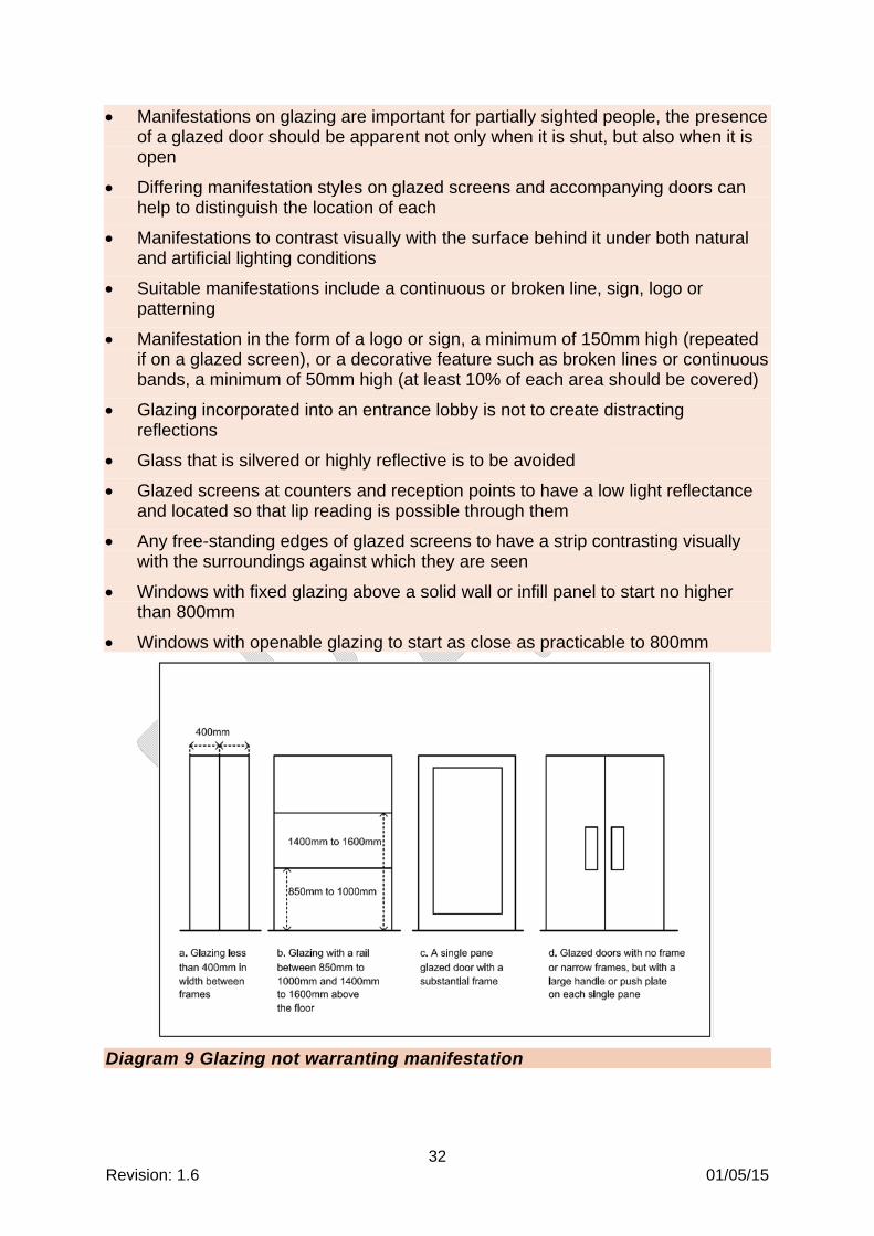
Manifestation in the form of a logo or sign, a minimum of 150mm high (repeated if on a glazed screen), or a decorative feature such as broken lines or continuous bands, a minimum of 50mm high (at least 10% of each area should be covered)
Glazing incorporated into an entrance lobby is not to create distracting reflections
Glass that is silvered or highly reflective is to be avoided
Glazed screens at counters and reception points to have a low light reflectance and located so that lip reading is possible through them
Any free-standing edges of glazed screens to have a strip contrasting visually with the surroundings against which they are seen
Windows with fixed glazing above a solid wall or infill panel to start no higher than 800mm
Windows with openable glazing to start as close as practicable to 800mm
Diagram 9 Glazing not warranting manifestation

33 Revision: 1.6 01/05/15
Diagram 10 Manifestation Heights

34 Revision: 1.6 01/05/15
6. Specific Areas
6.1 General Aims Facilities with the Campus should be usable by all people. Consideration should be given to providing facilities for disabled people within the same or similar location to standard facilities. This is to avoid segregation and perceived discrimination.
6.2 Study Areas – Hubs, Classrooms, Common Rooms and Labs – Aims
All rooms for study should be accessible and contain facilities to ensure navigation to, through and within them is intuitive and simple to carry out. Users of an area should also be able to easily control their environment by the use of switches and environmental controls.
Provisions – Study Areas – Hubs, Classrooms, Common Rooms and Labs The minimum space between rows of desks to accommodate wheelchair users
to be as shown in Diagram 11
Adjustable chairs to be provided within computer rooms
The height of a fixed desk surface to be between 730mm and 750mm, with the clear height under the desk of at least 700mm
Where feasible, adjustable height desks to be provided
Where projected images and videos are used, seating layouts to be flexible to enable partially sighted people to sit close to the screen
Where public address systems are installed within study areas, the acoustic properties of wall, ceiling and floor coverings are to be considered carefully to minimise echo and reverberation
A room suitable for interview purposes to be as shown in Diagram 12 (the dimensions of this room will need to be increased if a table is required)
Break-out areas to contain a mixture of seating, including fixed as well as removable seating, preferably with cushions provided
Seats with and without arm rests to be provided (including some fold down arms, which will meet the needs of a larger number of people)
The seat height to be between 450mm and 475mm (compressed cushion heights to be used)

35 Revision: 1.6 01/05/15
Diagram 11 Example table layout

36 Revision: 1.6 01/05/15
Diagram 12 Minimum dimensions of an interview room
Provisions – Café and Refectory Areas A 1500mm square space is required for a wheelchair user to manoeuvre
A space of 1800mm by 2000mm allows two wheelchair users to pass each other
Provide a self-service area with a continuous counter height of 850 mm
A table or counter with a height of 850mm to be provided within close proximity of the till
Provide a clear height of at least 700mm to the underside of any counters
Provide some tables with a clear height of 750mm to accommodate wheelchairs with armrests
Chairs to be moveable, with and without armrests provided
Provisions – Teaching Labs For work surfaces / sinks that are likely to be used for short periods a height of
850mm will accommodate both standing and seated users

37 Revision: 1.6 01/05/15
A maximum height of 760mm, with an underside of at least 700mm will accommodate wheelchair users
A height of 900mm minimum will accommodate standing users
Provide a height adjustable work surface to accommodate all users
Sinks with a depth of 150mm will enable easy reach of immersed items (using shallow sinks will also allow clearance space beneath work surfaces for seated users
Taps that can be used with a closed fist to be provided e.g. lever action
A knee recess of at least 650mm and 900mm wide to be provided
At least one space per specific task area to be provided for use by a wheelchair user, this includes consideration of reach ranges
Diagram 13 Lab Dimensions
6.3 Theatres and Audience Seating – Aims Theatres should be designed as accessible for performers and spectators, as well as staff and visitors.
Provisions – Theatres and Audience Seating Strive to make reasonable adjustments to improve the level of accessibility and
to maximise inclusion for all users within existing buildings
Routes between stage/performance areas and audience seating areas are to be accessible
Routes to ancillary areas or facilities used by staff, performers or spectators are to be accessible

38 Revision: 1.6 01/05/15
It is essential that barriers, fencing and balustrades do not obscure sightlines (this is particularly important for people who may not be able to change their position due to their impairment)
Sufficient audience seating provisions for both disabled and non-disabled people to be available
Table 2 indicates the provision of wheelchair user spaces required within audience seating
Wheelchair user seating areas to be provided measuring 1400mm in depth by 900mm wide
A clear circulation route of 1200mm to be provided behind wheelchair user seating areas
The wheelchair user seating areas are to be located to provide a variety of views and vantage points
The location of wheelchair user seating areas to be flexible to allow a wheelchair user to sit beside another wheelchair user, or a non-wheelchair using companion
Where possible provide power for electrical wheelchairs, mobility scooters and IT peripherals
Amenity seats measuring 500mm in width to be provided in varying locations (not only in areas that are available for wheelchair users and their companions)
Some amenity seats with additional leg-room to be provided (for assistance dogs)
Consideration to be given to the use of removable / retractable seating, which would maximise wheelchair user seating numbers and flexibility of locations
Seatways to have a minimum width of 300mm
The seatway of a fixed seat to be measured from the back of one seat to the front of the next seat
The seatway of an automatic or tip-up seat should be measured from the back of one seat to the nearest point of the next seat when in the upright position
A barrier to be provided within a maximum distance of 530mm from the front row of fixed seats, where there is a risk of falling
See Diagram 14 for seating measurements
Reasonable sightlines to be provided, this is particularly important for people who may not be able to change their position
Seating to contrast visually with the surrounding surfaces
Where possible all back of house areas including the stage are to be accessible with accessible toilet/shower facilities
Provide a hearing enhancement system for audience members (see Section 6.5 Acoustics and Communications Systems for details)

39 Revision: 1.6 01/05/15
Provision of wheelchair user spaces in audience seating
Seating capacity Minimum provision of spaces for wheelchair users
Permanent Removable
Up to 600 1% of total seating capacity (rounded up)
Remainder to make a total of 6
Over 600 but less than 10,000
1% of total seating capacity (rounded up)
Additional provision, if desired
Table 2 Audience seating provision
Diagram 14 Measurements for Seating

40 Revision: 1.6 01/05/15
Diagram 15 Example of wheelchair user seating spaces in a lecture theatre
Diagram 16 Minimum dimensions of wheelchair user seating spaces
6.4 Display Areas / Cases – Aims Display cases are usually glazed, which can cause glare and reflected images. This can be particularly distracting for partially sighted people. For this reason, it is

41 Revision: 1.6 01/05/15
important that display cases are carefully considered alongside lighting conditions, to ensure that the visibility of displays can be maximised for as wide an audience as possible.
Provisions – Display Areas / Cases Cases used to enclose exhibits to be carefully designed alongside the lighting
conditions, to ensure that glare and reflection is minimised
Labels on display cases to be located at the front of the case, set at 45°, preferably at the eye level of a seated person
Where possible, an additional higher level label to be provided with larger text
Labels to visually contrast with their surroundings
Provide a minimum of 70 light reflectance value (LRV) points difference between the text and the label background
Provide space around exhibits to circulate, and display cases are not to be placed in corners
Overhanging or low level barriers are not to be hazardous and warnings to be provided as appropriate for blind and partially sighted people
Floor textures where used, are not to conflict with the tactile language used elsewhere on the UCL Campus
Seating to be provided for reading literature and for general resting
Seating to be provided within a prominent position, but not on main circulation routes
Audio guides to be provided wherever possible to help guide blind and partially sighted people and allow them to enjoy the space
Audio guides are particularly useful when background noises of the environment being portrayed are played between descriptions
6.5 Libraries – Aims Libraries are an important area of study and should be as accessible as possible.
Provisions – New Libraries Provide an easy process for reserving books and retrieval e.g. online facilities
and/or an accessible information/collection desk
Provide bookshelves or drawer pulls for use by wheelchair users no lower than 400mm from the floor
Provide shelving for use by people who can stand but have reach difficulties no higher than 1625mm

42 Revision: 1.6 01/05/15
Provide shelving for use by people who can stand but have difficulties bending no lower than 700mm from the floor
Provide a clear space of at least 1200mm between shelving and a wall or storage unit
Provide a maximum shelf depth of 220mm where access is required to the back of shelves
For information regarding study tables see Diagram 11
6.6 Sports Buildings General sports facilities to follow the guidance contained within the following:
Sport England, April 2010, ‘Accessible Sports Facilities’.
Department for Culture, Media and Sport, 2009, ‘The Green Guide - “Guide to Safety at Sports Grounds”’.
6.7 Residential Buildings Residential facilities such as halls of residence are to be designed in consultation with the Local Authority to ensure their requirements are met/agreed.
Wheelchair accessible apartments are to follow the guidance contained within the Camden Wheelchair Housing Design Brief 2013,
6.8 Toilet and Shower Facilities – Aims The majority of disabled people do not require wheelchair accessible toilets; many disabled people who are ambulant prefer to use ambulant accessible cubicles (which are provided with grab-rails) or enlarged cubicles (an enlarged cubicle is helpful for people with luggage or with children).
Provisions – General Toilet and Shower Facilities Accessible toilet and/or shower provisions to be located together with standard
toilet and shower provision
Accessible toilets to be no more than 40m travel distance from any location in a building
To have accessible routes, free from obstructions, which are well lit and clearly signed
To contain adequate manoeuvring and transfer space for disabled people
To have a similar finish to standard toilet and/or shower provision (avoiding clinical or institutional designs)
To have fixtures and equipment that is operable by people with poor dexterity or limited strength (operable with one hand)

43 Revision: 1.6 01/05/15
To have good visual contrast between the main features, equipment and controls inside a cubicle
Not to have timed lighting systems
Not to have timed door closers
Door handles to be easy grip D handles and located on the back of doors
To have clothes hooks sited at 1050mm and 1400mm high
To have heating pipes and heating equipment carefully located and fitted with thermostatic controls
To have water delivered at a temperature to avoid scalding but taking into consideration requirements to avoid legionella
To be a link to the UCL alarm system
6.9 Accessible Toilets – Aims Disabled people should be able to find and use suitable toilet accommodation as easily as non-disabled people. The location of the toilet, basin and other accessories in relation to the space required for manoeuvring, is critical in enabling disabled people to use various transfer techniques that allow independent or assisted use of sanitary facilities.
Wheelchair users and other users of an accessible toilet often move more slowly than non-disabled people. Facilities therefore need to be provided within a reasonable travel distance from anywhere on a given floor plate to ensure that disabled people have access to the facility via the shortest available direct route.
Provisions – Accessible Toilets Within multi-storey buildings, wheelchair accessible toilets are to be located in
similar positions on each level and allow for right-hand and left-hand transfer on alternate floors
On large floor plates where multiple wheelchair accessible toilets are provided, alternate handed facilities to be available
Wheelchair accessible toilets are not to be designed to contain baby/child changing facilities.
To have finished room dimensions of at least 1500 x 2200mm with no services obstructing or reducing these (See Diagram 17)
To have a transfer space that is kept clear at all times
To have a flush lever placed on the open side of the toilet
To be fitted with an alarm and reset button that is registered at a security point
An accessible alarm push strip mounted around the perimeter of the toilet at an appropriate height is a recommended solution
To have riser seat attachments provided

44 Revision: 1.6 01/05/15
UCL require the provision of restricted access to certain Accessible WCs using a RADAR National Key Scheme (NKS) lock and key
Where an accessible WC forms part of a large suite of WCs or is located close to a large WC facility, the accessible WC is to be fitted with a RADAR key and lock
Where an accessible WC forms the only WC or one of a small number of standard WCs, the accessible WC is not to be fitted with a RADAR key and lock
RADAR keys will be managed and available from UCL Access Systems
Diagram 17 Accessible toilet (without lobby)
45 Revision: 1.6 01/05/15
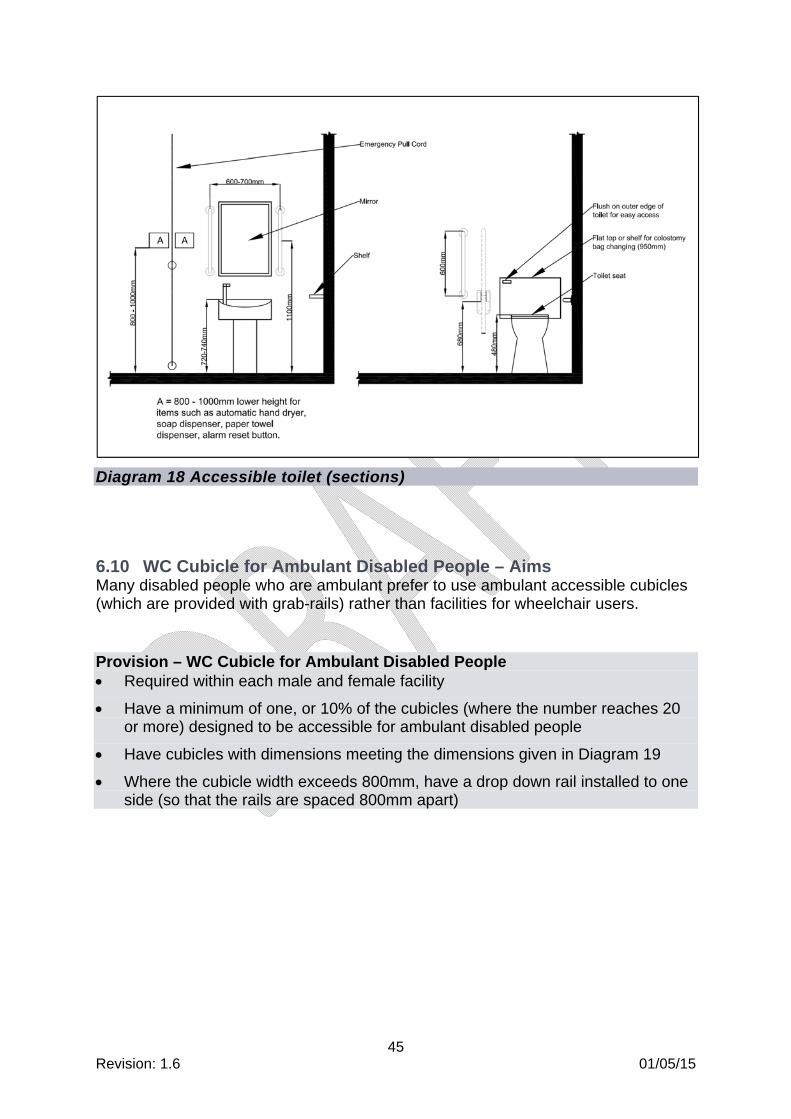
Diagram 18 Accessible toilet (sections)
6.10 WC Cubicle for Ambulant Disabled People – Aims Many disabled people who are ambulant prefer to use ambulant accessible cubicles (which are provided with grab-rails) rather than facilities for wheelchair users.
Provision – WC Cubicle for Ambulant Disabled People Required within each male and female facility
Have a minimum of one, or 10% of the cubicles (where the number reaches 20 or more) designed to be accessible for ambulant disabled people
Have cubicles with dimensions meeting the dimensions given in Diagram 19
Where the cubicle width exceeds 800mm, have a drop down rail installed to one side (so that the rails are spaced 800mm apart)

46 Revision: 1.6 01/05/15
Diagram 19 WC cubicle for ambulant disabled people
6.11 Enlarged Cubicles – Aims An enlarged cubicle is helpful for people with walking aids, luggage or with children.
Provisions – Enlarged Cubicles To be provided where there are four or more single-sex cubicles in a core
Provide cubicles with a width of 1200mm and length of 1500mm

47 Revision: 1.6 01/05/15
Provide a drop down table
6.12 Urinals
Provisions - Urinals Provide a level space of 900mm wide by 1400mm in length in front of a urinal for
wheelchair users
Vertical grab rails for the benefit of a disabled person who is standing should be provided on each side of a urinal where stall privacy dividers are not fitted.
The rim height of a urinal to be 500 mm above floor level for a standing person and 380 mm above floor level for a wheelchair user
In both instances, the urinal rim to project at least 360 mm from the wall
Urinals are to visually contrast with the wall
Where a urinal suitable for a wheelchair user is situated in a wheelchair-accessible male washroom, one washbasin with its rim between 680 mm and 700 mm should also be provided.
Urinals to follow the dimensions given in Diagram 20:
Diagram 20 Urinal Heights
6.13 Changing and Shower Facilities – Aims Sufficiently sized changing rooms must be provided to cater for the numbers of people expected to be using each facility. These may be individual changing /

48 Revision: 1.6 01/05/15
shower rooms or same sex changing / shower rooms with separate cubicles to maintain privacy.
Provisions – Changing and Shower Facilities Communal changing / shower areas are to have direct access between changing
and shower areas
Upstands are not to be used to separate wet and dry areas.
To have adjustable height detachable shower heads
To have benches at a usable height and depth
To have fold down seating and grab rails within shower areas for ambulant disabled people
To have areas within communal shower areas that are large enough for use by wheelchair users, including provision of grab rails and drop down seats
To have grooming areas for both standing and seated users
To have slip resistant floor finishes, even when wet (minimum pendulum test value (PTV) of 65)
Where separate wheelchair accessible shower / changing cubicles are provided, allow a wheelchair user to transfer to a shower seat without getting the wheelchair wet (refer to Diagram 22 for cubicle dimensions)
Lockers to be provided in a variety of sizes to accommodate for a range of needs for different people
Locks for lockers to be easy to use, one-handed, by a person with poor dexterity or limited strength in the hand or arm
Locks to be located no higher than 1150mm
It is recommended that 10% of lockers are accessible
Lockers to accommodate mobility aids, at least 300mm wide with a maximum depth of 600mm
To be mounted at a height between 400mm and 800mm

49 Revision: 1.6 01/05/15
Diagram 21 Changing room dimensions

50 Revision: 1.6 01/05/15
Diagram 22 Accessible Toilet with Shower
6.14 Changing Places Facility – Aims Although not within the Building Regulations, a Changing Places facility according to BS 8300 should be provided within an educational establishment. Consideration should therefore be given to providing at least one within the UCL Campus. A Changing Places facility is a room containing a combined toilet, shower and changing area which is used by disabled people who require assistance from up to two people.
Provisions – Changing Places Facility The room is required to be 12m squared with enough space to manoeuvre
around the furniture (refer to Diagram 23 for typical layout and requirements)
A fixed track hoist system that slings can be attached to is required to be installed, to enable the assistants to move the person around the facilities

51 Revision: 1.6 01/05/15
Diagram 23 Changing Places Facility
6.15 Families – Aims Family facilities including family toilets and baby/child changing facilities may also be required within public buildings (e.g. Theatre, Refectory) or those buildings deemed necessary by UCL. Locations and numbers should be discussed and agreed with UCL to ensure the correct provision is designed for inclusion within the Campus.
Provisions – Families Items required within a baby/child changing facility include the following:
Provide accessible, baby/child changing facilities but not within an accessible toilet
Similarly baby feed areas are not to be located within the general toilet provision

52 Revision: 1.6 01/05/15
Where possible (within public buildings such as the theatre), a children’s toilet to be integrated within the adult toilet cubicle (see Diagram 24 for layout)
Where there is only one cubicle in the building it should be accessible (see Diagram 24 for layout)
When providing a separate baby change room it should be accessible (see Diagram 25 for layout)
An adjustable height changing table that requires minimum effort to use to be provided
A safe, hygienic surface to be provided
Provide a paper roll dispenser for lining the table and cleaning babies that can be used with one hand
Provide shelf space for belongings and cleaning materials
Provide a disposal bin
The changing unit needs to accommodate older children who wear nappies
Provide a drop-down seat for small children
Diagram 24 Children’s toilet integrated within adult accessible toilet

53 Revision: 1.6 01/05/15
Diagram 25 Baby Change Facility
6.16 Quiet Contemplation Facilities – Aims Providing facilities to address the requirements of faith groups who are attending the Campus may be a consideration. This may include room set aside for multi-faith use or a ‘quiet room’ for contemplation.
Although unisex facilities are required to be inclusive, some faith groups will not use them, so careful consideration of these facilities will be required.
Provisions – Quiet Contemplation Facilities This may include a room set aside for multi-faith use or quiet contemplation, with
seating and neutral colours
So that use is encouraged by all, the room is not to contain religious pictures or ornaments
Toilet and washing facilities to be provided close by
Consideration to be given to the provision of separate-sex toilet and washing facilities (standard and accessible), in addition to any unisex accessible provision
For cultural reasons, communal shower/changing facilities may be unacceptable, as complete visual privacy is of utmost importance to some groups (agreement should be sought with UCL regarding what will be acceptable within each facility)
Additional ancillary facilities may also be required, such as a bidet or other sluice arrangements
Toilet pans and urinals are not to align with Mecca

54 Revision: 1.6 01/05/15
7. External Environment
7.1 General Navigating through the external environment within the UCL Campus should be as easy as possible for all users. An evolving Campus such as UCL contains existing and refurbished buildings, resulting in adjacent areas that do not complement one another, which can cause confusion. It is therefore important to assess elements on a case by case basis and when refurbishment works are carried out, finishes and surfaces will need to be considered carefully within the overall plan.
A combination of visual, tactile and audible cues are essential in assisting wayfinding for a variety of people, as well as reducing the risk of accident and injury for all pedestrians.
Provisions – External Environment General: Movement between buildings and areas of the site for pedestrians must be
accessible and barrier-free
Access routes should be designed to accommodate all users safely and, where possible, be covered to provide weather protection
Changes in level should be gradual over a shallow gradient
Where steps or stairs are necessary, a step free alternative should also be included within the same location
Clear lines of sight are necessary for maximising accessibility throughout pedestrian environments, for reducing confusion, and reducing dependence on signage and auditory information
Hazards along walkways, such as kerb upstands, must contrast visually with their surroundings, in addition to any freestanding features such as lighting poles, signage and street furniture
7.2 Pedestrian Movement – Crossing Points – Aims Crossing points should be safe and intuitive to use for all people. The provision of crossings, both controlled and uncontrolled, will need to be evaluated on a site by site basis and the rationale for any decisions documented within an Access Statement for approval by the Local Authority or Heritage Officer.
Where crossing signal systems are provided, they must be designed to allow adequate time for everyone to cross, and include visual, tactile and audible cues to notify people when it is safe to cross.

55 Revision: 1.6 01/05/15
Provisions – Pedestrian Movement – Crossing Points: Crossings should be located, where possible, along desire lines (for example,
align with entrances to buildings, parks, walkways, etc.) and shall be used to delineate preferred pedestrian routes
Crossings shall be located to minimise conflicts with traffic, be clearly marked and be strategically located to maximise accessibility to main destination points
Kerbs should be detectable by assistance dogs and long cane users, to create a safe route that people feel confident using
Kerbs to be maintained at a height of 150mm throughout, including raised crossing points
Double kerbs to be avoided as they are not user friendly
Each dropped kerb shall have a level area with a minimum width of 2000mm and a minimum length of 2000mm at the top of the dropped kerb, where located on an island
Width of islands shall be a minimum of 2000mm, this may need to be increased further (up to 3000mm), depending on the expected level of pedestrian flow (this will need to be evaluated on a site by site basis and the rationale for any decisions documented within an Access Statement for approval)
Raised islands in crossings shall be a cut-through level with the street or have dropped kerbs at both sides
Dropped kerbs to be incorporated at crossing points to provide step-free access for wheelchair users and other mobility impaired people
Tactile paving to be provided at crossing points to warn blind and partially sighted people of the hazard (see Tactile Paving information)
Crossings to be aligned to ensure that people are afforded straight approaches and arrival to safe areas
Raised crossings allow step-free access between the pavement and road (it is important to ensure that the boundary between pavement and road is made clear for people who are blind or partially sighted, by means of visually contrasting and tactile warning surfaces)

56 Revision: 1.6 01/05/15
Diagram 26 Uncontrolled Crossings
Diagram 27 Controlled Crossings

57 Revision: 1.6 01/05/15
Arrangement of minimum 2000mm Island
Arrangement of Island between 2000mm and 3000mm
Diagram 28 Refuge Islands

58 Revision: 1.6 01/05/15
Diagram 29 Refuge Island Staggered crossing
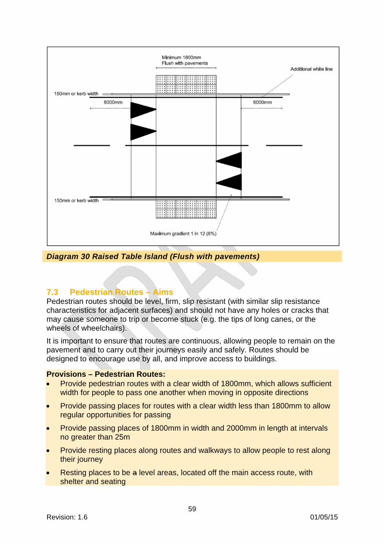
59 Revision: 1.6 01/05/15
Diagram 30 Raised Table Island (Flush with pavements)
7.3 Pedestrian Routes – Aims Pedestrian routes should be level, firm, slip resistant (with similar slip resistance characteristics for adjacent surfaces) and should not have any holes or cracks that may cause someone to trip or become stuck (e.g. the tips of long canes, or the wheels of wheelchairs).
It is important to ensure that routes are continuous, allowing people to remain on the pavement and to carry out their journeys easily and safely. Routes should be designed to encourage use by all, and improve access to buildings.
Provisions – Pedestrian Routes: Provide pedestrian routes with a clear width of 1800mm, which allows sufficient
width for people to pass one another when moving in opposite directions
Provide passing places for routes with a clear width less than 1800mm to allow regular opportunities for passing
Provide passing places of 1800mm in width and 2000mm in length at intervals no greater than 25m
Provide resting places along routes and walkways to allow people to rest along their journey
Resting places to be a level areas, located off the main access route, with shelter and seating

60 Revision: 1.6 01/05/15
Provide resting places at intervals no greater than 50m
Provide a clear headroom of 3000mm above a pedestrian route (this includes for bridges, tunnels and underpasses)
Routes to be well lit to enable safe access and confidence in use (refer to Section 5.4 Lighting for requirements)
7.4 Seating and Street Furniture - Aims Public areas should be designed for the benefit of everyone. This can be achieved by providing level access to all areas and facilities, incorporating seating, signage, weather protection, non-reflective finishes and ensuring walking surfaces are appropriate.
Street furniture (such as signposts and litter bins) and landscaped features (such as planting and water features) can cause barriers if they are not carefully designed with an appropriate location away from the main access route and suitable approach space. This may include the provision of warning information (tapping edges or tactile paving) if there is a risk of someone walking into the hazard.
Provisions – Seating: Provide resting places on circulation routes at regular intervals in commonly
used pedestrian areas (people with mobility impairments may need to rest and recover at more frequent intervals)
Rest areas to be located so as not to interfere with the flow of pedestrians
Maximum distance between resting places to be 50m
Rest areas to contain seating
Provide seating areas with a choice of different seats e.g. single seats and benches; with and without backrests and armrests
Provide resting places at intervals no greater than 50m
Provide a clear headroom of 3000mm above a pedestrian route (this includes for bridges, tunnels and underpasses)
Routes to be well lit to enable safe access and confidence in use (refer to Section 5.4 Lighting for requirements)
As an alternative to standard seating, provide perching seats, either fixed or pull-down, with and without backs, as casual rest places in longer circulation routes
Provide seats and benches at a seat height between 450mm and 480mm
Provide perching seats at a seat height between 650mm and 800mm
Armrests, when provided, to be 200mm above seat level
Locate seating on a suitable surface.
Where seats are located on soft landscaping, an associated accessible route (with a firm walking surface) will be required to access this.

61 Revision: 1.6 01/05/15
Provide seating designed to allow a wheelchair user or scooter user to sit alongside friends and family or in groups
Materials that are cold to the touch such as steel and concrete are to be avoided
Provide clearly identifiable seating e.g. visual contrast against background
It is preferable for rest and seating areas to be weather protected
Diagram 31 Example of indicative seating layout – Plan layout
Provisions – Street Furniture: Provide street furniture at or beyond the boundaries of pedestrian routes, placed
in areas that will not obstruct or create hazards for disabled people, especially for blind and partially sighted people.
Provide street furniture with smooth rounded edges (if impact occurs, this reduces the possibility of injury)
Street furniture to visually contrast with the surroundings in all lighting conditions
Bollards to be at least 1000mm high, and incorporate a 150mm wide band at the top for contrast (See Diagram 32)
Bollards are not to be linked e.g. by chains
A minimum width of 1000mm is required between bollards

62 Revision: 1.6 01/05/15
Any free-standing posts or columns provided within a circulation will require a minimum 150mm wide visually contrasting band located between 1400 and 1600mm
Protruding objects should not reduce the clear width required for accessible routes, with the exception of the next point
Where a protrusion is located at a height of 300mm minimum and 2100mm maximum from the floor, it is permitted to extend horizontally into the circulation route by 100mm maximum
Provide guarding (a minimum of 1100mm in height), a tapping rail or tactile warning, to prevent collision, for any protrusions exceeding the above point
A clear headroom of 3000mm minimum is required generally, although localised reductions are permitted. Reductions should be justified within the Access Statement however, they should be no lower than 2100mm
Provide barriers (a minimum of 1100mm in height), a tapping edge or tactile warning, shall be required to prevent access to areas that fall below the clearance in the above point, to avoid collision with the hazard
Low-level tapping rails to be 100mm in height to allow detection by long cane users
Fences and guardrails to be no lower than 1100mm (1200mm preferable)
Waste bins to be designed to the dimensions given in Diagram 33
Temporary street works on access routes need to be guarded by barriers, which shall have a minimum height of 1000mm
Further reference documents for temporary street works include DfT Safety at Street Works and Road Works A Code of Practice, October 2013; Chapter 8 of DfT Traffic Signs Manual
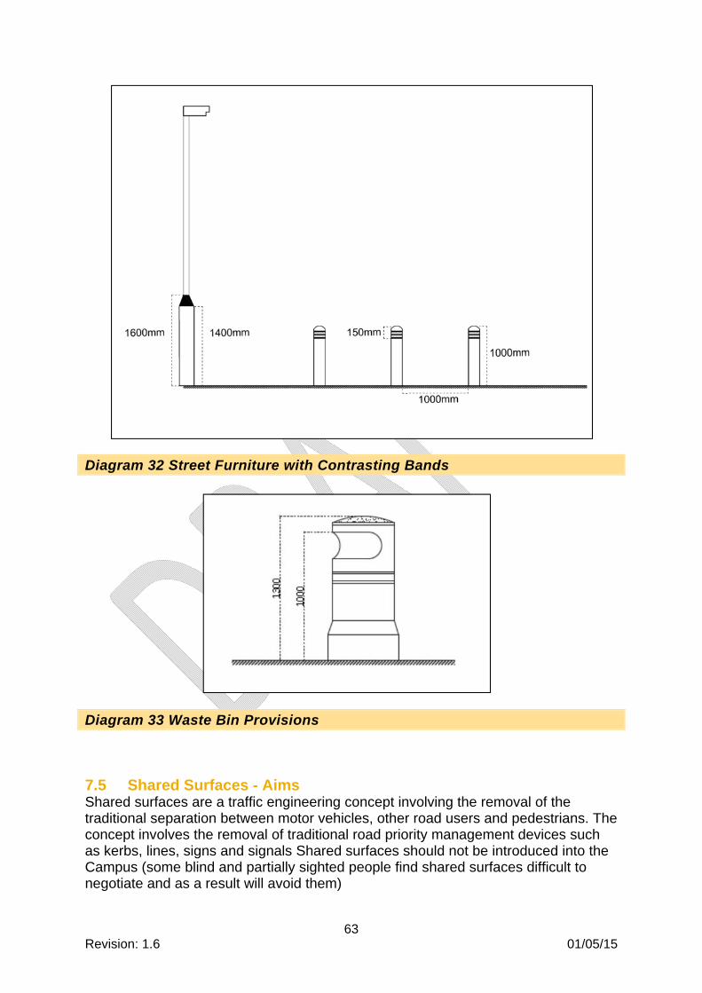
63 Revision: 1.6 01/05/15
Diagram 32 Street Furniture with Contrasting Bands
Diagram 33 Waste Bin Provisions
7.5 Shared Surfaces - Aims Shared surfaces are a traffic engineering concept involving the removal of the traditional separation between motor vehicles, other road users and pedestrians. The concept involves the removal of traditional road priority management devices such as kerbs, lines, signs and signals Shared surfaces should not be introduced into the Campus (some blind and partially sighted people find shared surfaces difficult to negotiate and as a result will avoid them)

64 Revision: 1.6 01/05/15
Provisions – Shared Surfaces: A ‘safe space’ should be provided
This ‘safe space’ should run along the length of the shared surface and be at least 1800mm in width
A visually contrasting delineator should be provided to act as a guide for blind and partially sighted people (refer to Section 5.7 for visual contrast)
A delineator strip, where provided, should be 150mm in width with a depth between 12mm and 15mm with a 50mm flat top (similar to cycle and pedestrian divided pathways)
The ‘safe space’ may also include a row of street furniture positioned to create a barrier between the buildings and the traffic
The deliberate placement of street furnishings and planting schemes, can have a traffic calming affect
7.6 Tactile Paving and Dropped Kerbs – Aims The main use of tactile paving is to identify the presence of hazards and to warn blind and partially sighted people of the potential hazard they are approaching, be it a change in level, approach to a crossing point, or an obstruction on the access route.
Tactile paving can also be used as a means of wayfinding, or facility indication (e.g. telephone booths, post boxes, etc)
Provisions – Tactile Paving and Dropped Kerbs: There are differing tactile paving types, which should be incorporated for the
appropriate application (type, colour, size and location)
The excessive use of tactile surfaces can cause confusion, it is therefore recommended that in areas where crowds of people are anticipated the use of tactile surfaces for wayfinding is limited
Blister paving should be reserved for use at crossing points only, and should be aligned in a square grid pattern as shown in Diagram 34
Corduroy paving should be reserved for use at the top and bottom of stairs and ramps (see Diagram 3 for details of provision)
Corduroy paving should be provided at a height of 6mm. Each rib should have a width of 20mm and there should be a gap between ribs of 30mm
Corduroy paving is not to be red in colour
Tactile paving should contrast visually with the remainder of the pavement. It is intended that UCL will standardise tactile paving, any provision to be discussed and agreed
Provide a consistent visual and tactile language to minimise confusion, including consideration of adjacent environments

65 Revision: 1.6 01/05/15
Diagram 34 Blister Paving Dome Size and Spacing
7.7 Relief Facilities for Assistance Dogs – Aims Assistance dogs are used by people with sight, hearing and mobility impairments.
t is recommended that, for public destinations where visit times are estimated at 5 hours or more, a relief facility for assistance dogs should be provided.
Provisions – Relief Facilities for Assistance Dogs: To be located in a secure area that is easy to find for a blind or partially sighted
person

66 Revision: 1.6 01/05/15
To have seating, a waste bin, a supply of plastic bags and “For assistance dogs only” signage
A suggested clear space of 3000 by 4000mm to be provided
It is suggested to have 50% soft surface (i.e. grass or sand) and 50% hard surface
To have a water supply etc in consultation with EM&I, with suitable crossfall (no steeper than 1:50) to facilitate cleaning and drainage
Consideration of a post or similar for male dogs to urinate against
Consideration of drinking water for assistance dogs
7.8 Smoking Shelters - Aims Smoking shelters are often used as areas for people to meet and socialise and therefore should be given the same attention as other sheltered meeting areas.
Provisions – Smoking Shelters: Smoking shelters, where provided, to be accessible and barrier-free
Shelters to be fully weather protected and include, where possible, seats with arm and back rests, perch seating and space for wheelchair users to rest alongside
Shelters to be naturally ventilated
7.9 Vehicular Facilities – Drop-off and Pick-up - Aims Drop-off and pick-up points are an important element for people who can’t walk long distances. In most instances they are an extension of the entrance to a building and should therefore be positioned as close to the entrance as possible.
Provisions – Vehicular Facilities – Drop-off and Pick-up To be provided within 50m of the entrance to any building
To be easily identifiable with signage provided (see Section 5.3 – Signage and Wayfinding)
Drop-off areas to be available for cars, taxis and coaches and will require dropped kerbs and tactile paving for safe and easy transfer between the road and pavement levels
Kerbs to be designed to be suitable for vehicle ramps and lifts, to offer a choice of transferring directly onto the pavement
It is preferable for these areas to be covered
Seating for waiting passengers should also be considered (where possible, this will include seats with arm and back rests, perch seating and space for wheelchair users to rest alongside)

67 Revision: 1.6 01/05/15
7.10 Car Parking - Aims Entrances into a car park can often be dangerous for pedestrians and even more so for those who are blind, partially sighted, or are wheelchair users. Pedestrian and vehicular access routes should be separated, and designed for safety and ease of use.
Some disabled people drive or use high-top vehicles which are specially adapted to accommodate a seated wheelchair user or a lift. Provisions must therefore include accessible bays and bays suitable for high-top conversion vehicles.
Provisions – Car Parking Designated parking bays for disabled motorists throughout the Campus must be
provided wherever car parking facilities are available
Any security measures (e.g. ticket barriers and entry controls) within car parks need to be designed to be accessible (see Section 5.6 Controls
Maintenance vehicles to be located away from pedestrian routes
Accessible parking bays to be in accordance with Diagram 35
Consideration should be given to making provision for people using a ‘drive from wheelchair’ vehicle (such drivers access their vehicles via a rear or side ramp or lift, which can require 2m clearance)
Provide signage on the surface of the bay as well as signage on a post (in case the ground becomes covered by snow or leaves)
Accessible parking bays to be within 50m of building entrances, or where this is not possible, suitable seating with arms and backrests should be provided at intervals of 50m
Provisions for accessible parking bays to include a minimum of one space for each employee who is a disabled motorist, (additional spaces for students and visitors should be determined through discussions with UCL and the Local Authority)
Walking surfaces to conform to Section 5.2 Walking Surfaces
For covered parking, the height limit to be shown on the approach and entry to the car park
For high top vehicles, a clear headroom of 2.6m is required, either provided within covered car parking, or allocated on-street bays
Provide directional signage from the car park entrance to the accessible parking bays for covered parking

68 Revision: 1.6 01/05/15
Diagram 35 Parking Bays for Disabled Motorists
7.11 Cycle Facilities - Aims Cycle parking, where provided, should be designed to enable access by disabled cyclists and storage of tandems and adapted cycles.
Provision - general cycle facilities: Space between stands – to be 700mm minimum, 1200mm preferable
Access around cycle stands – to be 3000mm minimum, 4000mm preferable
Provision - for disabled cyclists: Provision of stands with a marked, clear space to the side
Clear space to be 1000mm minimum width and 2500mm minimum length, which will accommodate most adapted cycles

69 Revision: 1.6 01/05/15
Diagram 36 Cycle Parking Including Space for Disabled Cyclists

70 Revision: 1.6 01/05/15
Appendix A
Signage
Standard information symbols:
International Symbol for Access, indicating routes and facilities with full accessibility
Facilities for Blind and Partially Sighted People
Facilities for Deaf People

71 Revision: 1.6 01/05/15
Hearing enhancement available for hearing aid users with a ‘T’ switch
Hearing enhancement available using infrared

72 Revision: 1.6 01/05/15
Appendix B Glossary and Abbreviations
A
Accessibility Accessibility refers to the ease of reaching destinations for users regardless of physical, sensory or cognitive restrictions. See also Universal Design.
Access Report/Access Statement
Documentation of the provisions for a project, in relation to accessibility. Used to facilitate the approvals process.
Ambulant Disabled Person
People with mobility impairment (not wheelchair users) – for example, people who use walking aids.
Assistance Dog A dog trained to aid or assist a disabled person in daily activities. Used by people with sight, hearing and mobility impairments.
Audits Review of existing buildings / facilities / environments to highlight non-compliances and identify ways of improving accessibility.
Audit Reports Documentation of an audit, highlighting remedial actions in order of priority.
B
Baby Changing
Rooms containing a bench, allowing parents and carers to change and attend to their children.
Blister Paving Tactile floor surface, detectable underfoot, to indicate the presence of a crossing point.
C
Changing Places Facility A toilet, shower and changing facility that allows use by wheelchair users (who are unable to use standard accessible toilets) and up to two assistants. This includes people with profound and multiple learning disabilities and their carers.
Clear Opening Width Unobstructed width provided by a door when it opens.
This width is measured from the furthest protrusion (normally the door hardware) and the door stop.
Closed Circuit Television (CCTV)
A system that sends television signals to a controlled centre, used to prevent crime.
Controlled Crossings A signalised crossing operated by pedestrians via a control button. This activates the traffic signals and in turn instructs motorists for a period of time to allow pedestrians to cross the road.
Corduroy Paving Tactile floor surface, detectable underfoot, to indicate the presence of a hazard (including stairs).
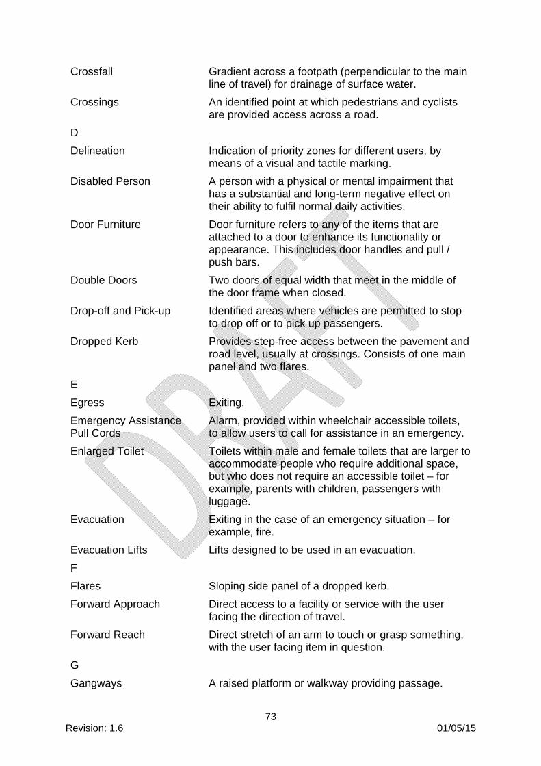
73 Revision: 1.6 01/05/15
Crossfall Gradient across a footpath (perpendicular to the main line of travel) for drainage of surface water.
Crossings An identified point at which pedestrians and cyclists are provided access across a road.
D
Delineation Indication of priority zones for different users, by means of a visual and tactile marking.
Disabled Person A person with a physical or mental impairment that has a substantial and long-term negative effect on their ability to fulfil normal daily activities.
Door Furniture Door furniture refers to any of the items that are attached to a door to enhance its functionality or appearance. This includes door handles and pull / push bars.
Double Doors Two doors of equal width that meet in the middle of the door frame when closed.
Drop-off and Pick-up Identified areas where vehicles are permitted to stop to drop off or to pick up passengers.
Dropped Kerb Provides step-free access between the pavement and road level, usually at crossings. Consists of one main panel and two flares.
E
Egress Exiting.
Emergency Assistance Pull Cords
Alarm, provided within wheelchair accessible toilets, to allow users to call for assistance in an emergency.
Enlarged Toilet Toilets within male and female toilets that are larger to accommodate people who require additional space, but who does not require an accessible toilet – for example, parents with children, passengers with luggage.
Evacuation Exiting in the case of an emergency situation – for example, fire.
Evacuation Lifts Lifts designed to be used in an evacuation.
F
Flares Sloping side panel of a dropped kerb.
Forward Approach Direct access to a facility or service with the user facing the direction of travel.
Forward Reach Direct stretch of an arm to touch or grasp something, with the user facing item in question.
G
Gangways A raised platform or walkway providing passage.

74 Revision: 1.6 01/05/15
Grab Bars A bar attached to a wall to provide a support for people who require it.
Grade 2 Braille Most common and appropriate type of Braille for use in public areas.
Graded Routes Gradients that are shallower than 1:20, therefore not considered to be ramps.
Gradients An incline along an access route.
Grey Scale A measure of tonal contrast, which related to the LRV percentages.
Guided Person A person who requires assistance, either by an assistance dog or another person.
H
Handrails A rail fixed to posts or a wall to provide support and guidance. Usually provided for stairs and ramps.
Hazard A danger or risk to health or safety.
Hearing Enhancement Systems
See AFILS.
Height Adjustable Counters
Work tops that can be changed in height, to allow people to adjust this to their individual requirements.
Help Points Identified areas or systems for easy access to emergency and information lines.
Horizontal Circulation Movement in the horizontal plane.
Illuminance The amount of luminous flux per unit area.
Infrastructure The physical and interconnecting structures supporting the operation of the transportation system. For example, streets and roads connecting to a transportation facility.
International Symbol for Accessibility
A blue square overlaid in white with an image of a person using a wheelchair. Used on signage to indicate the presence of accessible facilities and services.
Islands A raised area in the middle of a road that provides a safe place for pedestrians to stand and marks a division between two lanes of vehicular traffic.
J
Joints Point at which two paving slabs are joined.
K
Kerbs The edge between a pavement and a road, consisting of a line of kerbstones.

75 Revision: 1.6 01/05/15
Knee Clearance Recess beneath a surface to accommodate a person’s knees. For example, under a work surface, to allow someone to pull in closer to the work surface.
L
Landing Level area providing an opportunity for people to wait, rest or prepare for their journey. Usually provided at entrances, lifts, stairs and ramps.
Leaf The door leaf is the main part of the door that opens and closes within a fixed frame.
Leaf-and-a-half Two doors that meet in the middle of the door frame when closed, of unequal widths.
Light Reflectance Value (LRV)
LRV is a measurement of the amount of light reflected from a surface. It is measured by percentage. Pure white has a LRV of 100%; pure black has a LRV of 0%.
Lobbies A room providing a space out of which other rooms or corridors lead
LRV See Light Reflectance Value (LRV)
Lux The unit of illuminance, equal to one lumen per square meter.
M
Manifestations Visible markings on glazed surfaces. Required to highlight the presence of glazing to partially sighted persons.
Motion Sensors Devices to detect movement by measuring change in speed or vector of an object or objects in the field of view.
N
Newton (N) The unit of force, equal to the force that produces an acceleration of one meter per second per second on a mass of one kilogram.
Nosings The edge of a step.
O
Opening Forces Effort required to access a required item – for example, doors, buttons, controls.
Open Risers Stairs designed with open vertical surfaces between treads.
Overpasses A bridge by which a road or railroad passes over another.
P

76 Revision: 1.6 01/05/15
Passing Places Space for people to pass one another (for example, if moving in opposite directions).
Paving Slabs A precast concrete paving unit.
Pedestrian Routes Paths designated for use by pedestrians.
Perch Seating A seat that allows someone to rest in a standing position.
Personal Emergency Evacuation Plans (PEEPs)
An individual plan tailored to the needs of a disabled person. Defines the procedure for evacuation, including specific routes and any requirements for assistance.
Pictograms A pictogram is used in signage to convey meaning through its pictorial resemblance.
Q
Quiet Contemplation Facilities
Room with associated wash (ablution) facilities to provide people a quiet place to sit or worship.
R
Raised Character / Indication or Braille
Tactile information (embossed) to allow blind and partially sighted persons to read using the tips of their fingers.
Refreshment Facilities Tea points and kitchens for staff use.
Refuges Safe place for people to wait for assistance, in an evacuation.
Resting Places Spaces for people to rest along their journey, especially over longer routes and walking distances.
Retail Units to allow the sale of goods to the public.
Revolving Doors Doors with partitions that turn about a central axis.
Risers Vertical element of a step.
S
Side Reach Stretch of an arm to touch or grasp something, with the user parallel to the item in question.
Slip Resistance Materials with appropriate characteristics to prevent slippage or skidding.
Staff Welfare Areas Areas for staff working within a transportation facility including toilets and refreshment facilities.
Street Furniture Objects and pieces of equipment installed on streets and roads.
Streets A public road in a city or town.
Subways A tunnel under a road for use by pedestrians.
T

77 Revision: 1.6 01/05/15
Tactile Maps Maps with audible and tactile information to assist navigation for blind and partially sighted persons.
Tactile Paving Detectable underfoot, paving to assist navigation for blind and partially sighted persons.
Tactile Warning Detectable underfoot, paving to warn blind and partially sighted persons of hazards ahead.
Tapping Rail Low level upstand, detectable by a long cane, indicating edge of routes or presence of hazards to blind and partially sighted persons.
Tip-up Seat Seats that fold up when not in use.
Toe Clearance Recess beneath a surface to accommodate a wheelchair user’s toes and foot plate.
Treads Horizontal element of a step.
Turning Space Space required for a wheelchair user to turn through 360 degrees. This can consist of either a circular or a -square shaped space.
Two-way Communications A form of transmission in which both parties involved transmit information.
U
Uncontrolled Crossing A non-signalised crossing. This is reliant on visual communication between a pedestrian and motorist.
Urinals A receptacle, typically attached to a wall in a public toilet, into which men may urinate.
User Groups Groups consisting of the end user, who should be consulted as part of the design development, to ensure that the design is fit for purpose.
V
Vertical Circulation Movement in the vertical plane.
Vertical Clearance Headroom, clear of any obstructions and protrusions.
Vision Panels Panes of glass within a door, to allow people to see if someone is approaching from the opposite direction. Aim to avoid collision and injury.
W
Walking Aid A tool for providing support to maintain balance or stability when walking (could be a stick or a frame).
Weather Protection Protection from the natural elements. This may include purpose built canopies or overhanging upper floors of a building.
Wheelchair A wheelchair is a chair with wheels, designed to be a replacement for walking.
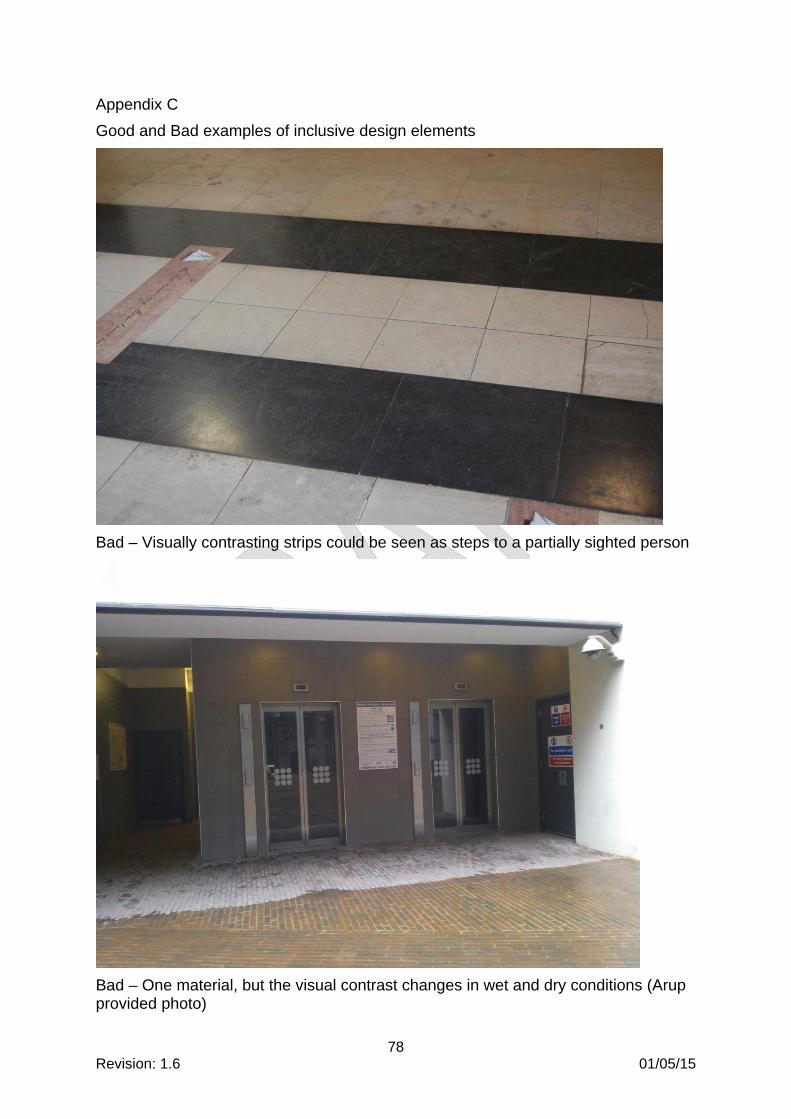
78 Revision: 1.6 01/05/15
Appendix C
Good and Bad examples of inclusive design elements
Bad – Visually contrasting strips could be seen as steps to a partially sighted person
Bad – One material, but the visual contrast changes in wet and dry conditions (Arup provided photo)

79 Revision: 1.6 01/05/15
Bad – Not enough visual contrast and a short kerb, which could create a tripping hazard (Byng Place)
Bad – An attempt to highlight a trip hazard, but with not enough visual contrast

80 Revision: 1.6 01/05/15
Bad – Nosings don’t provide enough visual contrast
Bad – Not enough visual contrast between floor, wall and door finishes

81 Revision: 1.6 01/05/15
Good – Totem in keeping with Legible London Signage
Bad – Placement, where obstructions can be put in the way

82 Revision: 1.6 01/05/15
Bad – Text size is too small for easy reading
Better – Easy to read sign with good visual contrast, pictograms could be larger

83 Revision: 1.6 01/05/15
Good – Signage very obvious and easy to read, both ramped and stepped access with visually contrasting ramp lengths and nosings on steps
Good – use of manifestations on glazing when doors are not in use

84 Revision: 1.6 01/05/15
Bad – Unclear where door opening is, unless door is open (Arup provided photos)
Better – Good visual contrast between wall and floor and door and wall. Further consideration could be given to the floor finish (dark colours may be mistaken as a void)

85 Revision: 1.6 01/05/15
Bad – Pooling of light from down-lighters and reflected light on shiny writing boards
Good – Projector at a height that won’t be disturbed by people walking in front, whiteboard at a good height for writing on

86 Revision: 1.6 01/05/15
Good – Visual contrast between obstructions/furniture (red chairs) and surroundings, choice of different table heights
Good – Collaborative working is possible, good visual contrast between furniture and floor

87 Revision: 1.6 01/05/15
Good – Adjustable height desks
Good – Adjustable height and position screens

88 Revision: 1.6 01/05/15
Appendix D
Bibliography
The following have been used as reference documents, the wording has been adapted for use by UCL:
Accessible Stadia, FLA, 2003
Approved Documents B, K and M of the Building Regulations
Assessing the slip resistance of flooring: A technical information sheet, Health and Safety Executive, 2007
BS 8300: 2009 + A1:2010 (Design of Buildings and their approaches to meet the needs of disabled people)
BS EN 81 Series
Building Bulletin 102, Designing for disabled children and children with special educational needs
Code for Lighting, Chartered Institution of Building Services Engineers (CIBSE), 2000
Designing for Accessibility, CAE and RIBA Enterprises, 2004
Gov.uk website
‘Green Guide’ Guide to Safety at Sports Grounds, Department for Culture, Media and Sport, 2009
Inclusive Mobility: A guide to best practice on access to pedestrian and transport infrastructure, Mobility and Inclusion Unit, Department for Transport, 2002
ODA Inclusive Design Standard
Safer surfaces to walk on – reducing the risk of slipping, CIRA, 2006
Technical Standards for Places of Entertainment, Association of British Theatre Technicians (ABTT), 2013