Embed Size (px)
Citation preview
Public Input No. 1-NFPA 59-2015 [ Global Input ]
Throughout standard remove references to the following and replace with thefollowing:
(1) ANSI/API and replace with API.
(2) ANSI/UL and replace with UL.
(3) API # and replace with API SPEC, STD, or RP #.
Statement of Problem and Substantiation for Public Input
Correlates with PI-2 and PI-3
Related Public Inputs for This Document
Related Input Relationship
Public Input No. 2-NFPA 59-2015[Section No. 2.3]
Referenced current SDO names, addresses, standard names,numbers, and editions.
Public Input No. 3-NFPA 59-2015[Section No. F.1.2]
Referenced current SDO names, addresses, standard names,numbers, and editions.
Submitter Information Verification
Submitter Full Name: Aaron Adamczyk
Organization: [ Not Specified ]
Street Address:
City:
State:
Zip:
Submittal Date: Sat Feb 07 19:49:55 EST 2015
National Fire Protection Association Report http://submittals.nfpa.org/TerraViewWeb/ContentFetcher?commentPara...
1 of 78 9/22/2015 11:20 AM
Public Input No. 5-NFPA 59-2015 [ Section No. 1.1.2 ]
1.1.2
Installations Utility Gas Plant installations that have LP-Gas storage containers having an aggregate water
capacity of 4000 gal (15.14 m3) or less, or of any size that do not have a vaporizer, shall conform to NFPA58, Liquefied Petroleum Gas Code.
Additional Proposed Changes
File Name Description Approved
PC_9_Held.pdf PC No. 9 - A2014
Statement of Problem and Substantiation for Public Input
NOTE: This Public Input appeared as Public Comment No. 9 which was "rejected but Held" in the Second Draft Report for NFPA 59 and per the regs at 4.4.8.3.1.
Most small installations of reticulated gas systems serving small networks or housing clusters have been installed under NFPA 58 which has adequate provisions for safety and protection for such systems. Adifferent factor is introduced into systems utilizing a vaporizer because of the possibility of liquid entering the distribution system. This factor necessitates a person with special knowledge to oversee the installation, operation and maintenance of the system. In vapor only systems this same level of expertise is not necessary and adequate safety is provided for under NFPA 58.
Submitter Information Verification
Submitter Full Name: TC on LPU-AAA
Organization: Technical Committee on LP-Gases at Utility Gas Plants
Street Address:
City:
State:
Zip:
Submittal Date: Thu Apr 09 11:27:07 EDT 2015
National Fire Protection Association Report http://submittals.nfpa.org/TerraViewWeb/ContentFetcher?commentPara...
2 of 78 9/22/2015 11:20 AM

Public Input No. 2-NFPA 59-2015 [ Section No. 2.3 ]
2.3 Other Publications.
2.3.1 API Publications.
American Petroleum Institute, 1220 L Street, NW, Washington, DC 20005-4070.
API SPEC 6FA, Specifications for Fire Tests for Valves, 2008 3rd edition, 1999, Reaffirmed 2011 .
API STD 607/ISO 10497 , Fire Test for Soft-Seated Quarter-Turn Valves , 2005 and ValvesEquipped with Nonmetallic Seats, 6th Edition, 2010 .
API STD 620, Design and Construction of Large, Welded, Low-Pressure Storage Tanks, 2008 with 2009addendum 1, 2010 addendum 2, and 2012 addendum 3 2013, Amendment 1, 2014 .
2.3.2 ASCE Publications.
American Society of Civil Engineers, 1801 Alexander Bell Drive, Reston, VA 20191-4400.
ASCE 7–05 7– 10 , Minimum Design Loads for Buildings and Other Structures, 2005 with Supplement #110th edition, 2010, Errata, 2011, and Revised Commentary 2013 .
2.3.3 ASME Publications.
American Society of Mechanical Engineers, Three ASME International , Two Park Avenue, New York,NY 10016-5990.
ASME Boiler and Pressure Vessel Code, 1949 and 2010 editions with July 2011 supplements 2015 .
ASME B31.3, Process Piping,2010 2014 .
2.3.4 ASTM Publications.
ASTM International, 100 Barr Harbor Drive, P.O. Box C700, West Conshohocken, PA 19428-2959.
ASTM A 47 A47 /A47M , Standard Specification for Ferritic Malleable Iron Castings, 2009 1999,Reapproved 2014 .
ASTM A 395 A395 /A395M , Specification for Ferritic Ductile Iron Pressure-Retaining Castings for Use atElevated Temperatures,2009 1999, Reapproved 2014 .
ASTM A 536 A536 , Specifications for Ductile Iron Castings,2009 1984, Reapproved 2014 .
2.3.5 UL Publications.
Underwriters Laboratories Inc., 333 Pfingsten Road, Northbrook, IL 60062-2096.
ANSI/ UL 132, Standard on Safety Relief Valves for Anhydrous Ammonia and LP-Gas, 2007, with Revised2010 amendment .
2.3.6 U.S. Government Publications.
U.S. Government Printing Government Publishing Office, Washington, DC 20402.
Title 49, Code of Federal Regulations, Part 192, “Pipeline Safety Law.”
2.3.7 Other Publications.
Merriam-Webster’s Collegiate Dictionary, 11th edition, Merriam-Webster, Inc., Springfield, MA, 2003.
Statement of Problem and Substantiation for Public Input
Referenced current SDO names, addresses, standards names, numbers, and editions.
Related Public Inputs for This Document
Related Input Relationship
Public Input No. 1-NFPA 59-2015 [Global Input]
National Fire Protection Association Report http://submittals.nfpa.org/TerraViewWeb/ContentFetcher?commentPara...
3 of 78 9/22/2015 11:20 AM

Public Input No. 3-NFPA 59-2015 [Section No. F.1.2]
Submitter Information Verification
Submitter Full Name: Aaron Adamczyk
Organization: [ Not Specified ]
Street Address:
City:
State:
Zip:
Submittal Date: Sat Feb 07 19:51:13 EST 2015
National Fire Protection Association Report http://submittals.nfpa.org/TerraViewWeb/ContentFetcher?commentPara...
4 of 78 9/22/2015 11:20 AM
Public Input No. 10-NFPA 59-2015 [ New Section after 2.3.1 ]
2.3.1 ACI Publications. American Concrete Institute, P.O. Box 9094, Farmington Hills, MI48333.
ACI 376 Code requirements for Design and Construction of Concrete Structures for the Containment ofRefrigerated Gases First Edition 2010 with Addendum 1, July 2013
Statement of Problem and Substantiation for Public Input
Insert ahead of 2.3.1 and renumber remaining. This new incorporated by reference standard is necessary to align with PI 6.3.4 which requires the application of this standard for the construction of foundations for refrigerated LPG storage tank systems.
Submitter Information Verification
Submitter Full Name: Michael Bellman
Organization: American Gas Association
Street Address:
City:
State:
Zip:
Submittal Date: Mon Jun 22 08:47:28 EDT 2015
National Fire Protection Association Report http://submittals.nfpa.org/TerraViewWeb/ContentFetcher?commentPara...
5 of 78 9/22/2015 11:20 AM
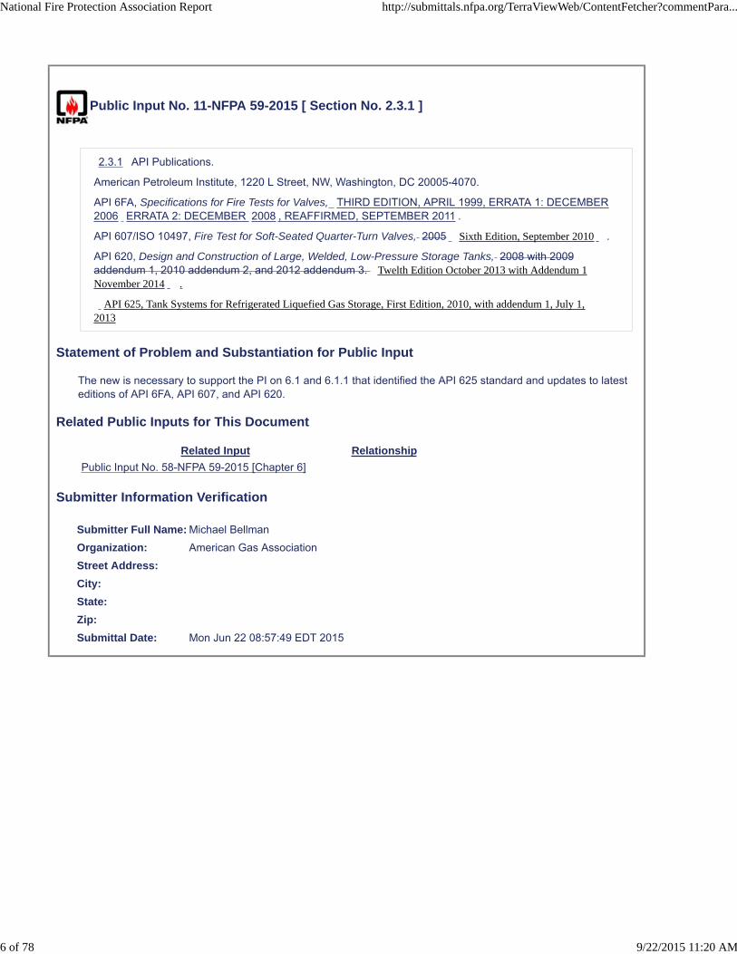
Public Input No. 11-NFPA 59-2015 [ Section No. 2.3.1 ]
2.3.1 API Publications.
American Petroleum Institute, 1220 L Street, NW, Washington, DC 20005-4070.
API 6FA, Specifications for Fire Tests for Valves, THIRD EDITION, APRIL 1999, ERRATA 1: DECEMBER2006 ERRATA 2: DECEMBER 2008 , REAFFIRMED, SEPTEMBER 2011 .
API 607/ISO 10497, Fire Test for Soft-Seated Quarter-Turn Valves, 2005 Sixth Edition, September 2010 .
API 620, Design and Construction of Large, Welded, Low-Pressure Storage Tanks, 2008 with 2009addendum 1, 2010 addendum 2, and 2012 addendum 3. Twelth Edition October 2013 with Addendum 1November 2014 .
API 625, Tank Systems for Refrigerated Liquefied Gas Storage, First Edition, 2010, with addendum 1, July 1,2013
Statement of Problem and Substantiation for Public Input
The new is necessary to support the PI on 6.1 and 6.1.1 that identified the API 625 standard and updates to latest editions of API 6FA, API 607, and API 620.
Related Public Inputs for This Document
Related Input Relationship
Public Input No. 58-NFPA 59-2015 [Chapter 6]
Submitter Information Verification
Submitter Full Name: Michael Bellman
Organization: American Gas Association
Street Address:
City:
State:
Zip:
Submittal Date: Mon Jun 22 08:57:49 EDT 2015
National Fire Protection Association Report http://submittals.nfpa.org/TerraViewWeb/ContentFetcher?commentPara...
6 of 78 9/22/2015 11:20 AM

Public Input No. 12-NFPA 59-2015 [ Section No. 2.3.2 ]
2.3.2 ASCE Publications.
American Society of Civil Engineers, 1801 Alexander Bell Drive, Reston, VA 20191-4400.
ASCE 7–05 7–10 , Minimum Design Loads for Buildings and Other Structures, 2005 with Supplement#1 2010 Third Printing; Incorporated Errata : January 11, 2011; Includes Supplement 1, and revisedcommentary, 2013 .
Statement of Problem and Substantiation for Public Input
Recognizes the latest edition of the ASCE 7 standard
Submitter Information Verification
Submitter Full Name: Michael Bellman
Organization: American Gas Association
Street Address:
City:
State:
Zip:
Submittal Date: Mon Jun 22 09:56:29 EDT 2015
National Fire Protection Association Report http://submittals.nfpa.org/TerraViewWeb/ContentFetcher?commentPara...
7 of 78 9/22/2015 11:20 AM
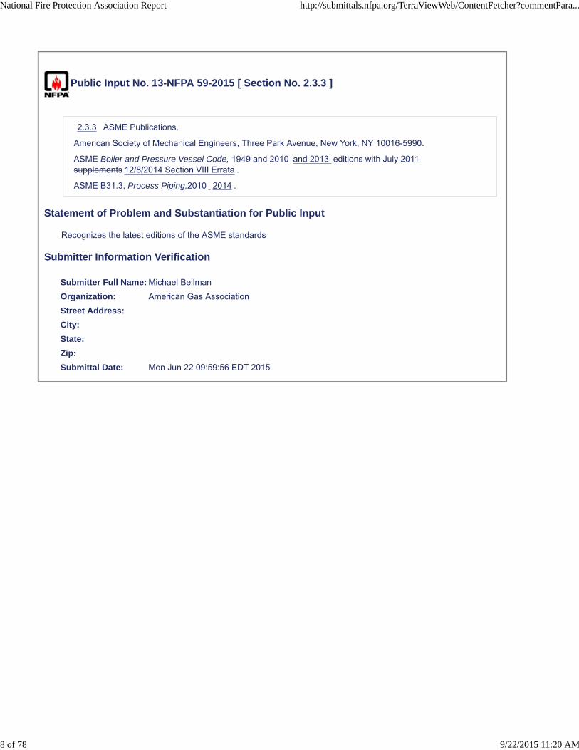
Public Input No. 13-NFPA 59-2015 [ Section No. 2.3.3 ]
2.3.3 ASME Publications.
American Society of Mechanical Engineers, Three Park Avenue, New York, NY 10016-5990.
ASME Boiler and Pressure Vessel Code, 1949 and 2010 and 2013 editions with July 2011supplements 12/8/2014 Section VIII Errata .
ASME B31.3, Process Piping,2010 2014 .
Statement of Problem and Substantiation for Public Input
Recognizes the latest editions of the ASME standards
Submitter Information Verification
Submitter Full Name: Michael Bellman
Organization: American Gas Association
Street Address:
City:
State:
Zip:
Submittal Date: Mon Jun 22 09:59:56 EDT 2015
National Fire Protection Association Report http://submittals.nfpa.org/TerraViewWeb/ContentFetcher?commentPara...
8 of 78 9/22/2015 11:20 AM
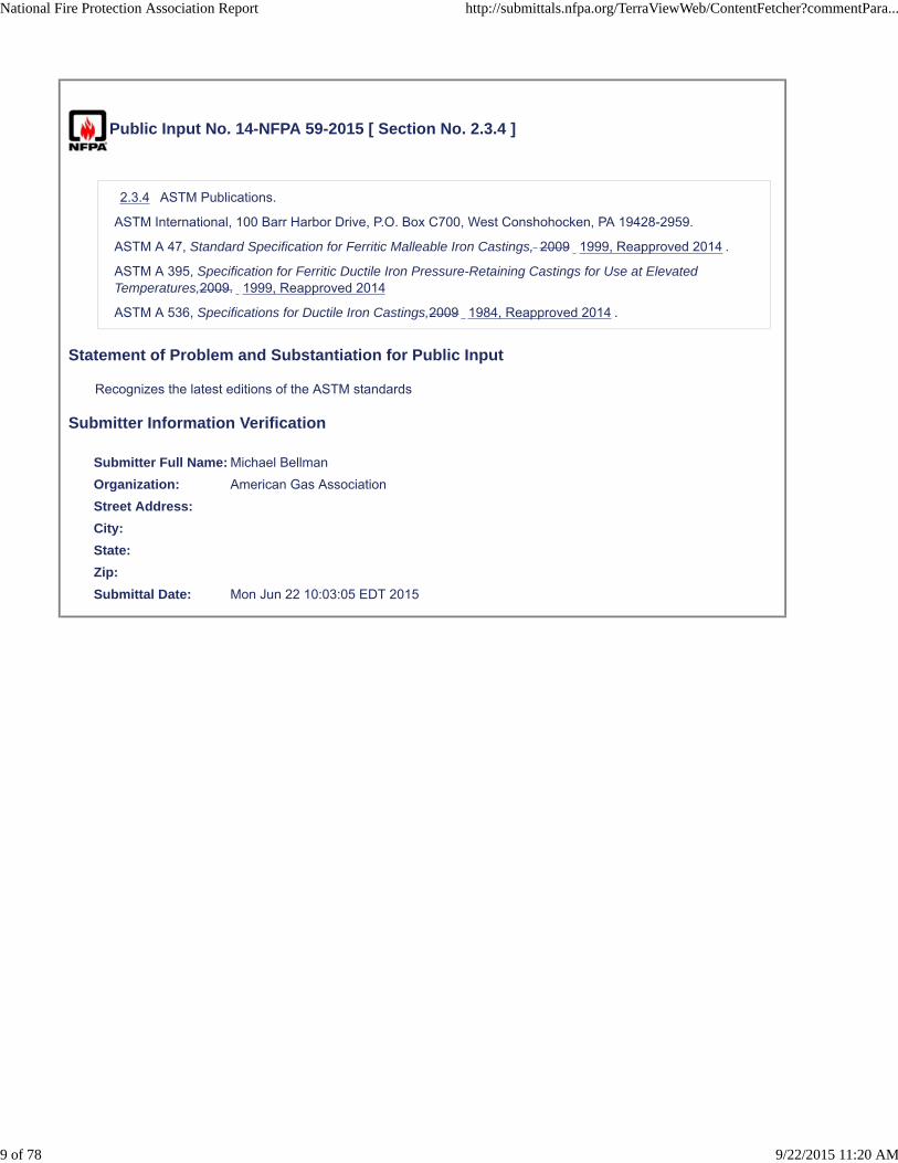
Public Input No. 14-NFPA 59-2015 [ Section No. 2.3.4 ]
2.3.4 ASTM Publications.
ASTM International, 100 Barr Harbor Drive, P.O. Box C700, West Conshohocken, PA 19428-2959.
ASTM A 47, Standard Specification for Ferritic Malleable Iron Castings, 2009 1999, Reapproved 2014 .
ASTM A 395, Specification for Ferritic Ductile Iron Pressure-Retaining Castings for Use at ElevatedTemperatures,2009. 1999, Reapproved 2014
ASTM A 536, Specifications for Ductile Iron Castings,2009 1984, Reapproved 2014 .
Statement of Problem and Substantiation for Public Input
Recognizes the latest editions of the ASTM standards
Submitter Information Verification
Submitter Full Name: Michael Bellman
Organization: American Gas Association
Street Address:
City:
State:
Zip:
Submittal Date: Mon Jun 22 10:03:05 EDT 2015
National Fire Protection Association Report http://submittals.nfpa.org/TerraViewWeb/ContentFetcher?commentPara...
9 of 78 9/22/2015 11:20 AM

Public Input No. 15-NFPA 59-2015 [ Section No. 2.3.5 ]
2.3.5 UL Publications.
Underwriters Laboratories Inc., 333 Pfingsten Road, Northbrook, IL 60062-2096.
ANSI/UL 132, Standard on Safety Relief Valves for Anhydrous Ammonia and LP-Gas, 2007, with 2010amendment Seventh Edition; Reprint with Revisions Through and Including February 9, 2015 .
Statement of Problem and Substantiation for Public Input
Recognizes the latest editions of the UL standard
Submitter Information Verification
Submitter Full Name: Michael Bellman
Organization: American Gas Association
Street Address:
City:
State:
Zip:
Submittal Date: Mon Jun 22 10:07:03 EDT 2015
National Fire Protection Association Report http://submittals.nfpa.org/TerraViewWeb/ContentFetcher?commentPara...
10 of 78 9/22/2015 11:20 AM

Public Input No. 9-NFPA 59-2015 [ Section No. 2.3.5 ]
2.3.5 UL Publications.
Underwriters Laboratories Inc., 333 Pfingsten Road, Northbrook, IL 60062-2096.
ANSI/UL 132, Standard on Safety Relief Valves for Anhydrous Ammonia and LP-Gas, 2007, with 2010amendment revised 2015 .
Statement of Problem and Substantiation for Public Input
The proposed change reflect revisions/update to the UL Standard.
Submitter Information Verification
Submitter Full Name: RONALD FARR
Organization: UL LLC
Street Address:
City:
State:
Zip:
Submittal Date: Mon Jun 15 11:00:36 EDT 2015
National Fire Protection Association Report http://submittals.nfpa.org/TerraViewWeb/ContentFetcher?commentPara...
11 of 78 9/22/2015 11:20 AM

Public Input No. 19-NFPA 59-2015 [ New Section after 3.3.8 ]
3.XXX Component
Component. A uniquely identifiable part, piece, assembly or subassembly that performs a distinctive andnecessary function in the operation of a LP-Gas facility or system. Components are usually removable inone piece and are considered indivisible for a particular purpose or use.
Statement of Problem and Substantiation for Public Input
Adding the definitions of Component incorporates terminology commonly used in the CFR 49 Part 192 code. Orienting the reader towards a hierarchy of definitions that include Component, Facility, and Plant provides clear understanding of the intent of the standard.
Related Public Inputs for This Document
Related Input Relationship
Public Input No. 22-NFPA 59-2015 [Section No. 4.8.2.2]
Submitter Information Verification
Submitter Full Name: Michael Bellman
Organization: American Gas Association
Street Address:
City:
State:
Zip:
Submittal Date: Mon Jun 22 10:25:25 EDT 2015
National Fire Protection Association Report http://submittals.nfpa.org/TerraViewWeb/ContentFetcher?commentPara...
12 of 78 9/22/2015 11:20 AM

Public Input No. 20-NFPA 59-2015 [ New Section after 3.3.11.2 ]
3.3.XXX Facility
Facility: A number of components, installed and designed to function as an independent process part of aLP-Gas plant.
Statement of Problem and Substantiation for Public Input
Adding the definition will orient the reader towards a hierarchy of definitions that include Component, Facility, and Plant provides clear understanding of the intent of the standard.
Related Public Inputs for This Document
Related Input Relationship
Public Input No. 21-NFPA 59-2015 [Section No. 4.8.2 [Excluding any Sub-Sections]]
Public Input No. 35-NFPA 59-2015 [Section No. 7.8.1]
Public Input No. 36-NFPA 59-2015 [Section No. 7.10.4.3]
Public Input No. 38-NFPA 59-2015 [Section No. 9.4.3 [Excluding any Sub-Sections]]
Public Input No. 42-NFPA 59-2015 [Section No. 12.3.8.1]
Public Input No. 48-NFPA 59-2015 [Section No. 13.1.1 [Excluding any Sub-Sections]]
Public Input No. 52-NFPA 59-2015 [Section No. 13.8.2.3]
Submitter Information Verification
Submitter Full Name: Michael Bellman
Organization: American Gas Association
Street Address:
City:
State:
Zip:
Submittal Date: Mon Jun 22 10:27:49 EDT 2015
National Fire Protection Association Report http://submittals.nfpa.org/TerraViewWeb/ContentFetcher?commentPara...
13 of 78 9/22/2015 11:20 AM
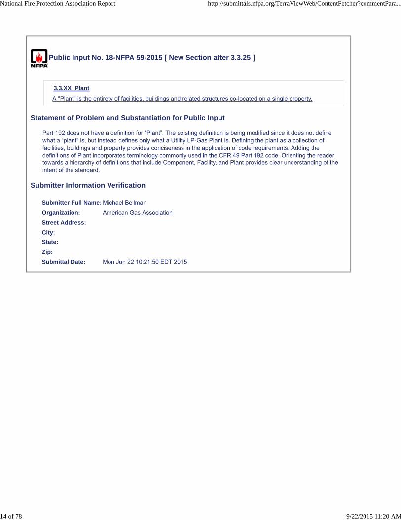
Public Input No. 18-NFPA 59-2015 [ New Section after 3.3.25 ]
3.3.XX Plant
A "Plant" is the entirety of facilities, buildings and related structures co-located on a single property.
Statement of Problem and Substantiation for Public Input
Part 192 does not have a definition for “Plant”. The existing definition is being modified since it does not define what a “plant” is, but instead defines only what a Utility LP-Gas Plant is. Defining the plant as a collection of facilities, buildings and property provides conciseness in the application of code requirements. Adding the definitions of Plant incorporates terminology commonly used in the CFR 49 Part 192 code. Orienting the reader towards a hierarchy of definitions that include Component, Facility, and Plant provides clear understanding of the intent of the standard.
Submitter Information Verification
Submitter Full Name: Michael Bellman
Organization: American Gas Association
Street Address:
City:
State:
Zip:
Submittal Date: Mon Jun 22 10:21:50 EDT 2015
National Fire Protection Association Report http://submittals.nfpa.org/TerraViewWeb/ContentFetcher?commentPara...
14 of 78 9/22/2015 11:20 AM

Public Input No. 16-NFPA 59-2015 [ New Section after 3.3.28 ]
3.3 Process Pressure Vessel
A vessel other than those used as a container for LPG (as defined in 3.3.9) that operates at pressuresexceeding 15 psig which is used as but not limited to part of the LPG loading/unloading process or forseparation, filtering, mixing/blending in the propane/propane-air supply process.
Statement of Problem and Substantiation for Public Input
The new definition supports new text proposed for Chapter 7 header and PI on 7.9
Submitter Information Verification
Submitter Full Name: Michael Bellman
Organization: American Gas Association
Street Address:
City:
State:
Zip:
Submittal Date: Mon Jun 22 10:14:45 EDT 2015
National Fire Protection Association Report http://submittals.nfpa.org/TerraViewWeb/ContentFetcher?commentPara...
15 of 78 9/22/2015 11:20 AM

Public Input No. 17-NFPA 59-2015 [ New Section after 3.3.30 ]
3.3.30 Refrigerated Storage Tank System.
3.3.30 Refrigerated Storage Tank System. Low pressure (less than 15 psi) equipment designed for the purposeof storing refrigerated LPG consisting of one or more containers, together with various accessories, appurtenances, andinsulation
Statement of Problem and Substantiation for Public Input
The new definition is necessary to support the PI on 6.1 and 6.1.1 that identified the API 625 standard
Related Public Inputs for This Document
Related Input Relationship
Public Input No. 58-NFPA 59-2015 [Chapter 6]
Submitter Information Verification
Submitter Full Name: Michael Bellman
Organization: American Gas Association
Street Address:
City:
State:
Zip:
Submittal Date: Mon Jun 22 10:18:07 EDT 2015
National Fire Protection Association Report http://submittals.nfpa.org/TerraViewWeb/ContentFetcher?commentPara...
16 of 78 9/22/2015 11:20 AM

Public Input No. 59-NFPA 59-2015 [ Section No. 3.3.36 ]
3.3.36* Utility Gas Plant.
A plant that stores and vaporizes LP-Gas for distribution that supplies either LP Gas or LP -Gas gas–airmixtures to a gas distribution system of 10 or more customers.
Statement of Problem and Substantiation for Public Input
This change would eliminate the applicability of the code to Undiluted LP Gas systems. Historically, the regulatory agencies have never recognized NFPA 59 to be applicable to these systems until just recently. The systems were not built to be compliant with 59 and the industry itself is experiencing an unnecessary burden by being made to comply. This proposal will provide a clear delineation of the scopes of NFPA 58 and NFPA 59 and as a result will allow the DOT Pipeline and Hazardous Materials Safety Administration (PHMSA) to easily adopt the new editions of both NFPA 58 and NFPA 59, thereby addressing the major stumbling block to consistent enforcement of 49 CFR Part 192.
Submitter Information Verification
Submitter Full Name: RUFUS YOUNGBLOOD
Organization: FERRELLGAS LP
Street Address:
City:
State:
Zip:
Submittal Date: Mon Jul 06 11:44:57 EDT 2015
National Fire Protection Association Report http://submittals.nfpa.org/TerraViewWeb/ContentFetcher?commentPara...
17 of 78 9/22/2015 11:20 AM

Public Input No. 57-NFPA 59-2015 [ Section No. 4.5.2.2 ]
National Fire Protection Association Report http://submittals.nfpa.org/TerraViewWeb/ContentFetcher?commentPara...
18 of 78 9/22/2015 11:20 AM

4.5.2.2 *
National Fire Protection Association Report http://submittals.nfpa.org/TerraViewWeb/ContentFetcher?commentPara...
19 of 78 9/22/2015 11:20 AM

Fixed electrical equipment and wiring installed within the classified areas specified in Table 4.5.2.2 shallcomply with Table 4.5.2.2 and shall be installed in accordance with NFPA 70, National Electrical Code.
Table 4.5.2.2 Electrical Area Classification
Part Location Extent of Classified Area a
Equipment Shallbe Approved for
NationalElectrical Code,
Class I a , Group
D b
A
Unrefrigerated containersother than cylinders andASME vertical containers ofless than 1000 lb (454 kg)water capacity
Within 15 ft (4.6 m) in all directions fromconnections, except connections otherwisecovered in Table 4.5.2.2
Division 2
B
Refrigerated storagecontainers
Within 15 ft (4.6 m) in all directions fromconnections otherwise covered in Table 4.5.2.2
Division 2
Area inside dike to the level of the top of thedike
Division 2
C c
Tank vehicle and tank carloading and unloading
Within 5 ft (1.5 m) in all directions fromconnections regularly made or disconnectedfor product transfer
Division 1
Beyond 5 ft (1.5 m) but within 15 ft (4.6 m) inall directions from a point where connectionsare regularly made or disconnected and withinthe cylindrical volume between the horizontalequator of the sphere and grade (see FigureA.4.5.2.2)
Division 2
D
Gauge vent openings otherthan those on cylinders andASME vertical containers ofless than 1000 lb (454 kg)water capacity
Within 5 ft (1.5 m) in all directions from point ofdischarge
Division 1
Beyond 5 ft (1.5 m) but within 15 ft (4.6 m) inall directions from point of discharge
Division 2
E Relief device discharge
other than those on cylinders and ASME vertical containers of less than 1000 lb (454 kg) water capacityand vaporizers
Within direct path of discharge
Within 5 feet (1.5m) in all directionsform point of discharge
Beyond 5 feet (1.5m) but within 15feet (4.5m) in all directions form pointof discharge
Division 1 ( Note: Fixed electrical equipment shouldpreferably not be installed ) .
Division 1
Division 2
F c
Pumps, vapor compressors, gas–airmixers and vaporizers (other thandirect-fired or indirect-fired with anattached or adjacent gas-fired heatsource)
Indoors without ventilationEntire room and any adjacent room not separated by agastight partition
Division1
Within 15 ft (4.6 m) of the exterior side of any exteriorwall or roof that is not vaportight or within 15 ft (4.6 m)of any exterior opening
Division2
National Fire Protection Association Report http://submittals.nfpa.org/TerraViewWeb/ContentFetcher?commentPara...
20 of 78 9/22/2015 11:20 AM

Indoors with ventilationEntire room and any adjacent room not separated by agastight partition
Division2
Outdoors in open air at or abovegrade
Within 15 ft (4.6 m) in all directions from this equipmentand within the cylindrical volume between thehorizontal equator of the sphere and grade (seeFigure A.4.5.2.2)
Division2
G
Pits or trenches containing or locatedbeneath LP-Gas valves, pumps,vapor compressors, regulators, andsimilar equipment
Without mechanical ventilation Entire pit or trenchDivision
1
Entire room and any adjacent room not separated by agastight partition
Division2
Within 15 ft (4.6 m) in all directions from pit or trenchwhen located outdoors
Division2
With mechanical ventilation Entire pit or trenchDivision
2
Entire room and any adjacent room not separated by agastight partition
Division2
Within 15 ft (4.6 m) in all directions from pit or trenchwhen located outdoors
Division2
H
Pipelines and connections containingoperational bleeds, drips, vents, ordrains
Within 5 ft (1.5 m) in all directions from point ofdischarge
Division1
Beyond 5 ft (1.5 m) from point of discharge, same aspart F of this table
I Piers and wharvesWithin 5 ft (1.5 m) in all directions from connectionsregularly made or disconnected for product transfer
Division1
Beyond 5 ft (1.5 m) but within 15 ft (4.6 m) in alldirections from a point where connections are regularlymade or disconnected and within the cylindricalvolume between the horizontal equator of the sphereand the vessel deck (see Figure A.4.5.2.2)
Division2
aThe classified area shall not extend beyond an unpierced wall, roof, or solid vaportight partition.
bSee Article 500 Hazardous (Classified) Locations, in NFPA 70, National Electrical Code, for definitions ofclasses, groups, and divisions.
cSee A.4.5.2.2.
Statement of Problem and Substantiation for Public Input
Changing only Table 4.5.2.2 Para E: The rationale for not identifying an electrical arear classification near safety relief valves has been based on the annex information in A.10.1 that states based on details in API 521 6.3.2.2, (2007 edition w/May 2008 Addendum) that during the discharge from a safety relief valve that the discharge velocity is such that sufficient volumes of air is entrained in the discharge stream and therefor dilutes the mixture to below the LEL. While this is stated in API 521, it is only applicable to safety relief valves discharging vapor. API 521 6.3.2.3, and 6.3.2.4 additionally describes the discharges of mists and liquids and goes onto state that the same air entrainment activity is not expected to occur and flammable concentrations in the area near the valves should be further evaluated. Safety relief valves in NFPA 59 facilities can be either in vapor or liquid service and for this reason the table has been changes to reflect the minimum hazardous area classifications. A PI for editing the annex material in A.10.1 shall also be submitted to clarify that the dilution phenomenon is only applicable to vapor service valves.
Related Public Inputs for This Document
National Fire Protection Association Report http://submittals.nfpa.org/TerraViewWeb/ContentFetcher?commentPara...
21 of 78 9/22/2015 11:20 AM

Related Input Relationship
Public Input No. 55-NFPA 59-2015 [Sections A.10.1, A.11.2.3]
Submitter Information Verification
Submitter Full Name: Michael Bellman
Organization: American Gas Association
Street Address:
City:
State:
Zip:
Submittal Date: Mon Jun 22 13:18:26 EDT 2015
National Fire Protection Association Report http://submittals.nfpa.org/TerraViewWeb/ContentFetcher?commentPara...
22 of 78 9/22/2015 11:20 AM

Public Input No. 21-NFPA 59-2015 [ Section No. 4.8.2 [Excluding any Sub-Sections] ]
Each new and modified plant modified facility shall retain records of materials of construction for processequipment piping systems containing LP-Gas and other flammable fluids, including their supporting systemand foundations.
Statement of Problem and Substantiation for Public Input
Standardizing the definitions of plant and facility see 20-NFPA 59-2015
Related Public Inputs for This Document
Related Input Relationship
Public Input No. 20-NFPA 59-2015 [New Section after 3.3.11.2]
Submitter Information Verification
Submitter Full Name: Michael Bellman
Organization: American Gas Association
Street Address:
City:
State:
Zip:
Submittal Date: Mon Jun 22 10:30:35 EDT 2015
National Fire Protection Association Report http://submittals.nfpa.org/TerraViewWeb/ContentFetcher?commentPara...
23 of 78 9/22/2015 11:20 AM

Public Input No. 22-NFPA 59-2015 [ Section No. 4.8.2.2 ]
4.8.2.2
Components such as pumps, compressors, valves, or similar assemblies components are not required tohave records of materials of construction. These records shall document that the assembled componenthas been designed and constructed per design with materials appropriate for the duty they serve.
Statement of Problem and Substantiation for Public Input
standardizing the definition of components
Related Public Inputs for This Document
Related Input Relationship
Public Input No. 19-NFPA 59-2015 [New Section after 3.3.8]
Submitter Information Verification
Submitter Full Name: Michael Bellman
Organization: American Gas Association
Street Address:
City:
State:
Zip:
Submittal Date: Mon Jun 22 10:33:40 EDT 2015
National Fire Protection Association Report http://submittals.nfpa.org/TerraViewWeb/ContentFetcher?commentPara...
24 of 78 9/22/2015 11:20 AM
Public Input No. 6-NFPA 59-2015 [ New Section after 4.8.2.3 ]
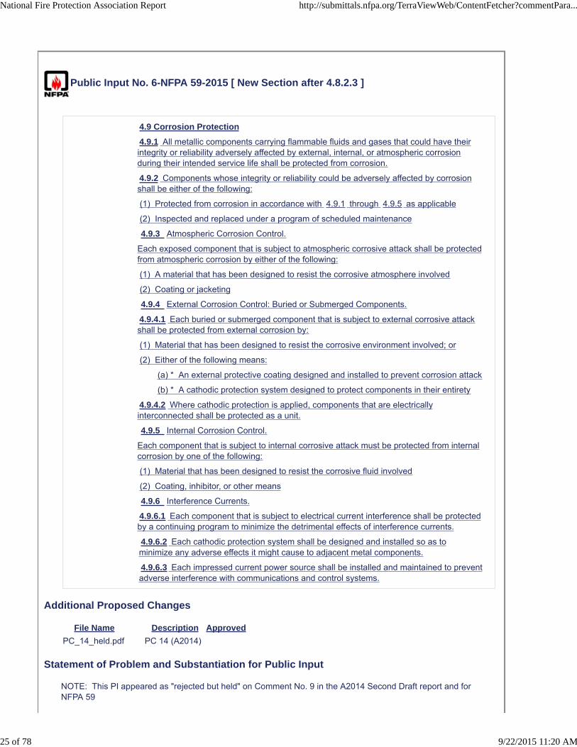
4.9 Corrosion Protection
4.9.1 All metallic components carrying flammable fluids and gases that could have theirintegrity or reliability adversely affected by external, internal, or atmospheric corrosionduring their intended service life shall be protected from corrosion.
4.9.2 Components whose integrity or reliability could be adversely affected by corrosionshall be either of the following:
(1) Protected from corrosion in accordance with 4.9.1 through 4.9.5 as applicable
(2) Inspected and replaced under a program of scheduled maintenance
4.9.3 Atmospheric Corrosion Control.
Each exposed component that is subject to atmospheric corrosive attack shall be protectedfrom atmospheric corrosion by either of the following:
(1) A material that has been designed to resist the corrosive atmosphere involved
(2) Coating or jacketing
4.9.4 External Corrosion Control: Buried or Submerged Components.
4.9.4.1 Each buried or submerged component that is subject to external corrosive attackshall be protected from external corrosion by:
(1) Material that has been designed to resist the corrosive environment involved; or
(2) Either of the following means:
(a) * An external protective coating designed and installed to prevent corrosion attack
(b) * A cathodic protection system designed to protect components in their entirety
4.9.4.2 Where cathodic protection is applied, components that are electricallyinterconnected shall be protected as a unit.
4.9.5 Internal Corrosion Control.
Each component that is subject to internal corrosive attack must be protected from internalcorrosion by one of the following:
(1) Material that has been designed to resist the corrosive fluid involved
(2) Coating, inhibitor, or other means
4.9.6 Interference Currents.
4.9.6.1 Each component that is subject to electrical current interference shall be protectedby a continuing program to minimize the detrimental effects of interference currents.
4.9.6.2 Each cathodic protection system shall be designed and installed so as tominimize any adverse effects it might cause to adjacent metal components.
4.9.6.3 Each impressed current power source shall be installed and maintained to preventadverse interference with communications and control systems.
Additional Proposed Changes
File Name Description Approved
PC_14_held.pdf PC 14 (A2014)
Statement of Problem and Substantiation for Public Input
NOTE: This PI appeared as "rejected but held" on Comment No. 9 in the A2014 Second Draft report and for NFPA 59
National Fire Protection Association Report http://submittals.nfpa.org/TerraViewWeb/ContentFetcher?commentPara...
25 of 78 9/22/2015 11:20 AM

Sections 12.2 to 12.2.6.3 in chapter 12 specify requirements for installation of corrosion protection and therefore should not be placed in the Maintenance chapter. Move these paragraphs to a new 4.9 in chapter 4.
Submitter Information Verification
Submitter Full Name: TC on LPU-AAA
Organization: Technical Committee on LP-Gases at Utility Gas Plants
Street Address:
City:
State:
Zip:
Submittal Date: Thu Apr 09 11:41:17 EDT 2015
National Fire Protection Association Report http://submittals.nfpa.org/TerraViewWeb/ContentFetcher?commentPara...
26 of 78 9/22/2015 11:20 AM

Public Input No. 23-NFPA 59-2015 [ Section No. 5.6.1 ]
5.6.1
Containers once installed underground or aboveground that have been out of service for more than 1 yearshall not be reinstalled aboveground or underground unless they withstand , without distortion, hydrostaticpressure retests a successful hydrostatic pressure retest at the pressure specified for the originalhydrostatic test as required by the code under which they were constructed.
Statement of Problem and Substantiation for Public Input
There is no practical way to verify "distortion" of the storage tank, and this text is not common language for these types of tests
Submitter Information Verification
Submitter Full Name: Michael Bellman
Organization: American Gas Association
Street Address:
City:
State:
Zip:
Submittal Date: Mon Jun 22 10:44:43 EDT 2015
National Fire Protection Association Report http://submittals.nfpa.org/TerraViewWeb/ContentFetcher?commentPara...
27 of 78 9/22/2015 11:20 AM

Public Input No. 61-NFPA 59-2015 [ Section No. 5.6.1 ]
5.6.1
Containers once installed underground or aboveground that have been out of service for more than 1 yearshall not be reinstalled aboveground or underground unless they withstand, without distortion, hydrostaticpressure retests at the pressure specified for the original hydrostatic test as required by the code underwhich they were constructed are given a thorough inspection in accordance with the ANSI/NB23 NationalBoard Inspection Code .
Statement of Problem and Substantiation for Public Input
The requirement is too restrictive and should be revised. Many ASME tanks in the propane industry are left out of service for long periods of time with no adverse effect.
Submitter Information Verification
Submitter Full Name: RUFUS YOUNGBLOOD
Organization: FERRELLGAS LP
Street Address:
City:
State:
Zip:
Submittal Date: Mon Jul 06 11:51:50 EDT 2015
National Fire Protection Association Report http://submittals.nfpa.org/TerraViewWeb/ContentFetcher?commentPara...
28 of 78 9/22/2015 11:20 AM

Public Input No. 60-NFPA 59-2015 [ Section No. 5.8.1 ]
5.8.1
Point of transfer shall be at least 75 ft (23 m) from uncontrolled sources of ignition, process areas, and 25 ft(7.62 m) from control buildings, offices, shops, and other occupied or important plant structures, other thanequipment directly associated with the transfer operation.
Statement of Problem and Substantiation for Public Input
The distance requirement is too restrictive and should be revised. NFPA 58 allows Point of Transfer spacing of 25 to buildings with other than at least 1 hour fire rated walls.
Submitter Information Verification
Submitter Full Name: RUFUS YOUNGBLOOD
Organization: FERRELLGAS LP
Street Address:
City:
State:
Zip:
Submittal Date: Mon Jul 06 11:49:15 EDT 2015
National Fire Protection Association Report http://submittals.nfpa.org/TerraViewWeb/ContentFetcher?commentPara...
29 of 78 9/22/2015 11:20 AM

Public Input No. 58-NFPA 59-2015 [ Chapter 6 ]
Chapter 6 Refrigerated Containers
6.1 Construction and Design of Refrigerated Containers.
[ 58: 12.1]
6.1.1 Container Material and Construction Requirements.
[ 58: 12.1.1]
6.1.1.1
Containers designed to operate at greater than 15 psi (103 kPa) shall be designed and constructed inaccordance with the ASME Boiler and Pressure Vessel Code , Section VIII, except that construction usingjoint efficiencies listed in Table UW 12, Column C, shall not be permitted. [ 58: 12.1.1.1]
6.1.1.2
Materials used in refrigerated containers shall be selected from those included in the following:
(1) ASME Boiler and Pressure Vessel Code , Section VIII (materials that maintain their integrity at theboiling temperature of the liquid stored)
(2) API Standard 620, Design and Construction of Large, Welded, Low-Pressure Storage Tanks,Appendix R or Appendix Q
[ 58: 12.1.1.2]
6.1.1.3
Containers designed to operate below 15 psi (103 kPa) shall be in accordance with API Standard 620,Design and Construction of Large, Welded, Low-Pressure Storage Tanks, including Appendix R.[ 58: 12.1.1.3]
6.1.1.4
Where austenitic stainless steels or nonferrous materials are used, API Standard 620, Design andConstruction of Large, Welded, Low-Pressure Storage Tanks, Appendix Q, shall be used in the selectionof materials. [ 58: 12.1.1.4]
6.1.1.5
All new construction shall incorporate on any bottom or side penetrations that communicate with the liquidspace of the container either an internal emergency shutoff valve or a back check valve. Any emergencyshutoff valve shall be incorporated into a facility emergency shutdown system and be capable of beingoperated remotely. [ 58: 12.1.1.5]
6.1.2 Container Design Temperature and Pressure.
[ 58: 12.1.2]
6.1.2.1
The maximum allowable working pressure shall include a margin above the operating pressure.
National Fire Protection Association Report http://submittals.nfpa.org/TerraViewWeb/ContentFetcher?commentPara...
30 of 78 9/22/2015 11:20 AM

6.1.2.2
The design pressure of ASME containers shall include a minimum 5 percent of the absolute vaporpressure of the LP-Gas at the design storage temperature. The margin (both positive and vacuum) forlow-pressure API Standard 620, Design and Construction of Large, Welded, Low-Pressure StorageTanks , vessels shall include the following:
(1) Control range of the boil-off handling system
(2) Effects of flash or vapor collapse during filling operations
(3) Flash that can result from withdrawal pump recirculation
(4) Normal range of barometric pressure changes
[ 58: 12.1.2.1]
6.1.2.3
The design temperature for those parts of a refrigerated LP-Gas container that are in contact with the liquidor refrigerated vapor shall be equal to or lower than the boiling point of the product to be stored atatmospheric pressure. A temperature allowance shall be made for the composition of the liquid to bestored when it is flashed into the vapor space of a tank. [ 58: 12.1.2.2]
6.2 Marking on Refrigerated LP-Gas Containers.
[ 58: 12.2]
6.2.1
Each refrigerated LP-Gas container shall be identified by the attachment of a nameplate located either onthe container or in a visible location. [ 58: 12.2.1]
6.2.2
The nameplate shall be in accordance with API Standard 620, Design and Construction of Large, Welded,Low-Pressure Storage Tanks, Section 6. [ 58: 12.2.2]
6.3 Container Installation.
[ 58: 12.3]
6.3.1 Wind Loading.
[ 58: 12.3.1]
6.3.1.1
The design wind loading on refrigerated LP-Gas containers shall be in accordance with the projected areaat various height zones above ground in accordance with ASCE 7, Minimum Design Loads for Buildingsand Other Structures . [ 58: 12.3.1.1]
6.3.1.2
Design wind speeds shall be based on a mean occurrence interval of 100 years. [ 58: 12.3.1.2]
6.3.2 Seismic Loading.
[ 58: 12.3.2]
6.3.2.1
The design seismic loading on refrigerated LP-Gas containers shall be in accordance with ASCE 7,Minimum Design Loads for Buildings and Other Structures . [ 58: 12.3.2.1]
6.3.2.2
A seismic analysis of the proposed installation shall be made that meets the approval of the authorityhaving jurisdiction. [ 58: 12.3.2.2]
6.3.3 Piping.
[ 58: 12.3.3]
National Fire Protection Association Report http://submittals.nfpa.org/TerraViewWeb/ContentFetcher?commentPara...
31 of 78 9/22/2015 11:20 AM

6.3.3.1
All piping that is part of a refrigerated LP-Gas container and refrigerated LP-Gas systems, includingtransfer and process piping, shall be in accordance with ASME B31.3, Process Piping . [ 58: 12.3.3.1]
6.3.3.2
The container piping shall include the following:
(1) All piping internal to the container
(2) All piping within the insulation spaces
(3) All external piping attached or connected to the container up to the first circumferential external jointof the piping
[ 58: 12.3.3.2]
6.3.3.3
Inert gas purge systems wholly within the insulation spaces shall be exempt from the provision in 6.3.3.1 .[ 58: 12.3.3.3]
6.3.4 Foundations.
[ 58: 12.3.4]
6.3.4.1
Refrigerated aboveground containers shall be installed on foundations that have been engineered for sitesoil conditions and loadings. [ 58: 12.3.4.1]
6.3.4.2
Prior to the start of design and construction of the foundation, a subsurface investigation shall beconducted by a soils engineer. Foundations shall be designed by an engineer who is experienced infoundations and soils. [ 58: 12.3.4.2]
6.3.4.3
Where product storage is at less than 30°F (−1.1°C), the foundation and the container bottom shall complywith the following:
(1) The foundation design and the container bottom insulation shall prevent damage to the containerfrom frost heave.
(2) If the refrigerated LP-Gas container under bottom foundation and insulation are in contact with thesoil, and the soil temperature can be less than 32°F (0°C), a heating system shall be installed toprevent the soil temperature from falling below 32°F (0°C).
(3) The under-container heating system shall be designed to allow both functional and performancemonitoring.
(4) The under-container temperature shall be observed and logged at least weekly.
(5) Where the foundation has a discontinuity, such as bottom piping, the heating system in that zoneshall be designed for the discontinuity.
(6) The under-container heating system shall be installed so that any heating elements or temperaturesensors used for control can be replaced while the container is in service.
(7) Provisions shall be incorporated to minimize the effects of moisture accumulation in the conduit andother forms of deterioration within the conduit or heating element.
[ 58: 12.3.4.3]
6.3.4.4
The refrigerated LP-Gas container foundation shall be periodically monitored for settlement during the lifeof the facility. [ 58: 12.3.4.4]
6.3.4.5
The monitoring shall include construction, hydrostatic testing, commissioning, and operation. [ 58: 12.3.4.5]
National Fire Protection Association Report http://submittals.nfpa.org/TerraViewWeb/ContentFetcher?commentPara...
32 of 78 9/22/2015 11:20 AM

6.3.4.6
Any settlement in excess of that anticipated in the design shall be investigated, and corrective action shallbe taken if appropriate. [ 58: 12.3.4.6]
6.3.4.7
For a container having a double wall design, the bottom of the outer wall and the refrigerated LP-Gascontainer under-container insulation shall be above the groundwater table or protected from contact withgroundwater at all times. It shall also be protected from floodwaters. [ 58: 12.3.4.7]
6.3.4.8
Where two or more containers are sited in a common dike, the container foundations shall be constructedof material resistant to the effects of refrigerated LP-Gas and the temperatures to which they will beexposed. [ 58: 12.3.4.8]
6.3.4.9
If the foundation of a refrigerated LP-Gas container is designed to provide air circulation in lieu of a heatingsystem, the foundation and insulating material under the bottom of the container shall be constructed ofmaterials that are resistant to the effects of refrigerated LP-Gas and the temperatures to which they will beexposed. [ 58: 12.3.4.9]
6.3.4.10
The material in contact with the bottom of the container shall be selected to minimize corrosion.[ 58: 12.3.4.10]
6.4 Refrigerated LP-Gas Container Instruments and Controls.
[ 58: 12.4]
6.4.1 Gauging Devices.
[ 58: 12.4.1]
6.4.1.1
Each refrigerated LP-Gas container shall be equipped with at least two independent liquid level gaugingdevices. [ 58: 12.4.1.1]
6.4.1.2
Liquid level gauging devices shall be installed so that they can be replaced without taking the container outof service. [ 58: 12.4.1.2]
6.4.1.3
The refrigerated LP-Gas container shall be provided with an audible and visual high–liquid level alarm.[ 58: 12.4.1.3]
6.4.1.4
The alarm shall be set so that the operator will have sufficient time, based on the maximum allowable fillingrate, to stop the flow without exceeding the maximum permissible filling height. [ 58: 12.4.1.4]
6.4.1.5
The alarm shall be located so that it is visible and audible to the personnel who control the filling.[ 58: 12.4.1.5]
6.4.1.6
A high–liquid level flow cutoff device shall not be a substitute for the alarm. [ 58: 12.4.1.6]
6.4.2 High–Liquid Level Device.
6.4.2.1
The refrigerated LP-Gas container shall be equipped with a high-high-liquid level flow cutoff device that isindependent from all gauges. [ 58: 12.4.1.7]
National Fire Protection Association Report http://submittals.nfpa.org/TerraViewWeb/ContentFetcher?commentPara...
33 of 78 9/22/2015 11:20 AM

6.4.2.2
Where refrigerated LP-Gas containers of 70,000 gal (265 m 3 ) or less are attended during the fillingoperation, they shall be equipped with either liquid trycocks or a high–liquid level alarm, and manual flowcutoff shall be permitted. [ 58: 12.4.1.8]
6.4.2.3
Each refrigerated LP-Gas container shall be provided with temperature-indicating devices that assist incontrolling cooldown rates when placing the tank in service and monitoring product temperatures duringoperations. [ 58: 12.4.1.9]
6.4.3 Pressure and Vacuum Control.
[ 58: 12.4.2]
6.4.3.1
Provisions shall be made to maintain the container pressure within the limits set by the designspecifications by releasing or admitting gas as needed. Provision for admission and release of gas shall beby any means compatible with the gas-handling facilities in the plant. [ 58: 12.4.2.1]
6.4.3.2
The option of gas admission (or other gas or vapor if so designed) through the vacuum relief valvesprovided in API Standard 620, Design and Construction of Large, Welded, Low-Pressure Storage Tanks ,paragraph 7.2.3, shall not be permitted.
6.5 Refrigerated LP-Gas Container Impoundment.
[ 58: 12.5]
6.5.1
Each refrigerated LP-Gas container shall be located within an impoundment that complies with Section6.5 . [ 58: 12.5.1]
6.5.2
Enclosed drainage channels for LP-Gas shall be prohibited. [ 58: 12.5.2]
6.5.3
Impoundment for refrigerated LP-Gas containers shall have a volumetric holding capacity, with anallowance made for the displacement of snow accumulation, other containers, or equipment that is equal tothe total liquid volume of the largest container served, assuming that container is full to the high–liquid levelflow cutoff device. [ 58: 12.5.4]
6.5.4
Where more than one container is installed in a single impoundment and if an outside container wall isused as a spill containment dike, the material shall be selected to withstand exposure to the temperature ofrefrigerated LP-Gas liquid. [ 58: 12.5.5]
6.5.5
Impoundment structures and any penetrations thereof shall be designed to withstand the full hydrostatichead of the impounded LP-Gas and the effects of the product composition and the resultingautorefrigeration temperatures. [ 58: 12.5.6]
6.5.6
Impoundment structures shall also be nonporous and resistant to natural forces such as wind, rain, andfire. [ 58: 12.5.7]
6.5.7
Provisions shall be made to clear rain or other water from the impounding area. [ 58: 12.5.8]
National Fire Protection Association Report http://submittals.nfpa.org/TerraViewWeb/ContentFetcher?commentPara...
34 of 78 9/22/2015 11:20 AM

6.5.7.1
Where automatically controlled sump pumps are used, they shall be equipped with an automatic shutoffdevice that prevents their operation when either of the following occurs:
(1) They are exposed to the flash temperature of the liquid LP-Gas.
(2) Flammable vapors in excess of 25 percent of the lower flammable limit are detected within theimpoundment area.
6.5.7.2
Gravity drainage utilizing piping penetrations through or below impoundment dikes shall not be permitted.[ 58: 12.5.8.3]
6.5.8
If the container impounding area is an earthen dike system, the area topography of the impounding areafloor shall be graded away from the container to prevent the accumulation of liquid under or around thecontainer. [ 58: 12.5.9]
6.5.8.1
The grading shall move the spilled liquid to the toe of the dike system and as far away from the containeras possible. [ 58: 12.5.9.1]
6.5.8.2
The grading shall move the spilled liquid to a subimpoundment basin that is capable of holding the quantityof liquid spilled from a line rupture, a flange leak, or a source other than container failure. [ 58: 12.5.9.2]
6.5.8.3
The duration of the incident shall be the amount of time that automatic systems or plant personnel couldeffect emergency procedures and stop the leak. The subimpoundment basin shall be located as far awayfrom the container as possible. [ 58: 12.5.9.3]
6.6 Inspection and Testing of Refrigerated LP-Gas Containers and Systems.
[ 58: 12.6]
6.6.1
During construction and prior to the initial operation or commissioning, each refrigerated LP-Gas containerand system shall be inspected or tested in accordance with the provisions of this code and the codes andstandards referenced herein. [ 58: 12.6.1]
6.6.2
The inspections or tests required shall be conducted by the operator or a third-party engineering, scientific,recognized insurance, or inspection organization.
6.6.3
Each inspector shall be qualified in accordance with the code or standard that is applicable to the test orinspection being performed. [ 58: 12.6.3]
6.6.4
After acceptance tests are completed, there shall be no field welding on the LP-Gas containers exceptwhere allowed by the code under which the container was fabricated. [ 58: 12.6.4]
6.6.5
Retesting shall be required only if the retest tests the element affected and is necessary to demonstrate theadequacy of the repair or modification. [ 58: 12.6.5]
6.7 Container Siting.
[ 58: 12.7]
6.7.1
[Please see SUGGESTED Reorganization and rewrite of NFPA 59 Chapter 6 fromAmerican Gas Association, Supplemental Gas Committee, Attached]
National Fire Protection Association Report http://submittals.nfpa.org/TerraViewWeb/ContentFetcher?commentPara...
35 of 78 9/22/2015 11:20 AM

6.3.10.1
Spacing of refrigerated LP-Gas containers designed to operate at greater than 15 psi (103 kPa) fromoccupied buildings, storage containers for flammable or combustible liquids, and lines of adjoining propertythat can be built upon shall be in accordance with Table 6.7.1. [58:12.7.1]
Table 6.7.1 Minimum Distances for Refrigerated LP-Gas Containers That Operate at 15 psi (103 kPa) andHigher
Water Capacity per Container Aboveground Containers
gal m 3 ft m
≤70,000 ≤265 75 23
70,001–90,000 265–341 100 30
90,001–120,000 341–454 125 38
120,001–200,000 454–757 200 61
200,001–1,000,000 757–3785 300 91
>1,000,000 >3785 400 122
[58: Table 12.7.1]
6. 7 2 . 2 10
Spacing of refrigerated LP-Gas containers that operate at below 15 psi (103 kPa) from occupied buildings,storage containers for flammable or combustible liquids, and lines of adjoining property that can be builtupon shall be in accordance with Table 6.7.2. [58:12.7.2]
Table 6.7.2 Minimum Distances for Refrigerated LP-Gas Containers That Operate Below 15 psi (103 kPa)
Water Capacity per Container Aboveground Containers
gal m 3 ft m
≤70,000 ≤265 75 25
>70,000 >265 100 30
[ 58: Table 12.7.2]
6.7.3
The edge of a dike, impoundment, or drainage system that is intended for a refrigerated LP-Gas containershall be 100 ft (31 m) or more from a property line that can be built upon, a public way, or a navigablewaterway. [ 58: 12.7.3]
6.7.4
Nonrefrigerated LP-Gas containers or flammable liquid tanks shall not be located within dikes orimpoundments enclosing refrigerated LP-Gas containers. [ 58: 12.7.4]
6.7.5
Refrigerated LP-Gas containers shall not be installed one above the other. [ 58: 12.7.5]
6.7.6
The minimum distance between aboveground refrigerated LP-Gas containers shall be one-half thediameter of the larger container. [ 58: 12.7.6]
6.7.7
The ground within 25 ft (7.6 m) of any aboveground refrigerated LP-Gas container, and all ground within adike, impoundment, or drainage area, shall be kept clear of readily ignitible materials such as weeds andlong, dry grass. [ 58: 12.7.7]
Additional Proposed Changes
File Name Description Approved
National Fire Protection Association Report http://submittals.nfpa.org/TerraViewWeb/ContentFetcher?commentPara...
36 of 78 9/22/2015 11:20 AM

Chapter_6_for_attachment.doc
SUGGESTED Reorganization and rewrite of NFPA 59 Chapter 6 from American Gas Association, Supplemental Gas Committee
Statement of Problem and Substantiation for Public Input
In the 1998 edition of NFPA 59, NFPA 59 began extracting the entire refrigerated container section from NFPA 58. Prior to the 1998 edition of NFPA 59, the NFPA 59 standard included very similar text that was in NFPA 58 but it was not officially extracted from NFPA 58. Over the last several years, the standards development organizations have developed a series of including one new standard (API 625) and revising two existing standards (API 620 and ACI 376) such that a low pressure refrigerated storage container must apply all three standards to design, engineer, construct, examine and test a new storage tank.
Related Public Inputs for This Document
Related Input Relationship
Public Input No. 11-NFPA 59-2015 [Section No. 2.3.1]
Public Input No. 17-NFPA 59-2015 [New Section after 3.3.30]
Public Input No. 24-NFPA 59-2015 [Section No. 6.5.8.3]
Submitter Information Verification
Submitter Full Name: Michael Bellman
Organization: American Gas Association
Street Address:
City:
State:
Zip:
Submittal Date: Thu Jun 25 07:23:46 EDT 2015
National Fire Protection Association Report http://submittals.nfpa.org/TerraViewWeb/ContentFetcher?commentPara...
37 of 78 9/22/2015 11:20 AM

Public Input No. 24-NFPA 59-2015 [ Section No. 6.5.8.3 ]
6.5.8.3
The duration of the incident shall be the amount of time that automatic systems or plant personnel couldeffect emergency procedures and stop the leak. The subimpoundment basin shall be located as far awayfrom the container as possible. [ 58: 12.5.9.3]
Statement of Problem and Substantiation for Public Input
The statement on the duration of the incident is not definitive and has no value to this section.
Related Public Inputs for This Document
Related Input Relationship
Public Input No. 58-NFPA 59-2015 [Chapter 6]
Submitter Information Verification
Submitter Full Name: Michael Bellman
Organization: American Gas Association
Street Address:
City:
State:
Zip:
Submittal Date: Mon Jun 22 10:48:32 EDT 2015
National Fire Protection Association Report http://submittals.nfpa.org/TerraViewWeb/ContentFetcher?commentPara...
38 of 78 9/22/2015 11:20 AM

Public Input No. 25-NFPA 59-2015 [ Chapter 7 [Title Only] ]
Piping, Valves, Process Pressure Vessels and Equipment
Statement of Problem and Substantiation for Public Input
The additional recognition of process pressure vessels that may be used and are not storage containers by definition
Related Public Inputs for This Document
Related Input Relationship
Public Input No. 26-NFPA 59-2015 [New Section after 7.8.5]
Submitter Information Verification
Submitter Full Name: Michael Bellman
Organization: American Gas Association
Street Address:
City:
State:
Zip:
Submittal Date: Mon Jun 22 10:52:39 EDT 2015
National Fire Protection Association Report http://submittals.nfpa.org/TerraViewWeb/ContentFetcher?commentPara...
39 of 78 9/22/2015 11:20 AM
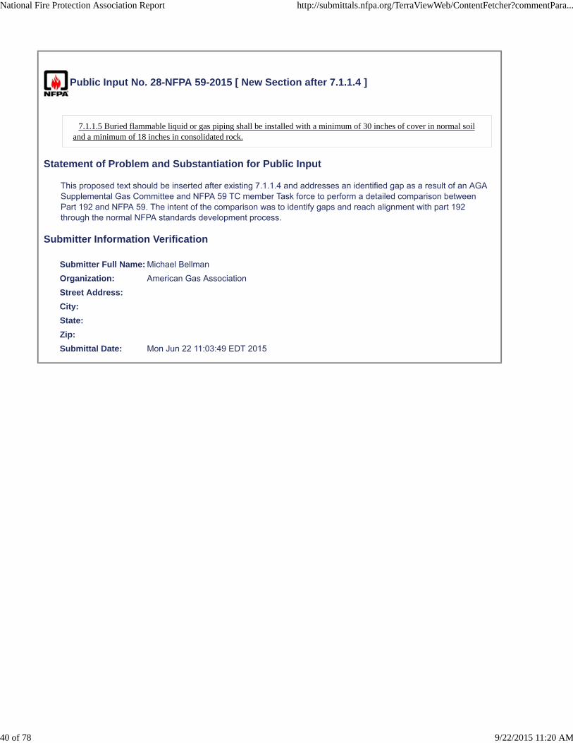
Public Input No. 28-NFPA 59-2015 [ New Section after 7.1.1.4 ]
7.1.1.5 Buried flammable liquid or gas piping shall be installed with a minimum of 30 inches of cover in normal soiland a minimum of 18 inches in consolidated rock.
Statement of Problem and Substantiation for Public Input
This proposed text should be inserted after existing 7.1.1.4 and addresses an identified gap as a result of an AGA Supplemental Gas Committee and NFPA 59 TC member Task force to perform a detailed comparison between Part 192 and NFPA 59. The intent of the comparison was to identify gaps and reach alignment with part 192 through the normal NFPA standards development process.
Submitter Information Verification
Submitter Full Name: Michael Bellman
Organization: American Gas Association
Street Address:
City:
State:
Zip:
Submittal Date: Mon Jun 22 11:03:49 EDT 2015
National Fire Protection Association Report http://submittals.nfpa.org/TerraViewWeb/ContentFetcher?commentPara...
40 of 78 9/22/2015 11:20 AM

Public Input No. 29-NFPA 59-2015 [ New Section after 7.1.1.4 ]
7.1.1.6 Buried flammable liquid or gas piping shall be installed with a minimum of 12 inches clearance between thepipe and any other structure not associated with the pipe to allow for proper maintenance
Statement of Problem and Substantiation for Public Input
This proposed text should be inserted after proposed new 7.1.1.5 and addresses an identified gap as a result of an AGA Supplemental Gas Committee and NFPA 59 TC member Task force to perform a detailed comparison between Part 192 and NFPA 59. The intent of the comparison was to identify gaps and reach alignment with part 192 through the normal NFPA standards development process
Submitter Information Verification
Submitter Full Name: Michael Bellman
Organization: American Gas Association
Street Address:
City:
State:
Zip:
Submittal Date: Mon Jun 22 11:06:16 EDT 2015
National Fire Protection Association Report http://submittals.nfpa.org/TerraViewWeb/ContentFetcher?commentPara...
41 of 78 9/22/2015 11:20 AM

Public Input No. 30-NFPA 59-2015 [ Section No. 7.1.11 ]
7.1.11
Piping outside buildings shall be supported and protected against physical damage and corrosion.
Statement of Problem and Substantiation for Public Input
All piping should be protected, not just piping outside buildings.
Submitter Information Verification
Submitter Full Name: Michael Bellman
Organization: American Gas Association
Street Address:
City:
State:
Zip:
Submittal Date: Mon Jun 22 11:08:40 EDT 2015
National Fire Protection Association Report http://submittals.nfpa.org/TerraViewWeb/ContentFetcher?commentPara...
42 of 78 9/22/2015 11:20 AM

Public Input No. 27-NFPA 59-2015 [ Section No. 7.2.5 ]
7.2.5
All liquid and vapor connections on containers, other than pressure relief valves, liquid level gaugingdevices, and openings not larger than No. 54 drill size 0.055 inches as covered in 7.2.6 and 7.4.3, shallbe equipped with one of the following:
(1) A back-pressure check valve and either a manual valve or an emergency shutoff valve
(2) An excess-flow valve with a fail-closed hydraulic or pneumatically actuated valve in compliance withAPI 607, Fire Test for Soft-Seated Quarter-Turn Valves; API 6FA, Specifications for Fire Tests forValves; or the equivalent, equipped for remote closure and automatic shutoff using thermal (fire)actuation where the thermal element is installed in compliance with 7.1.5
(3) A quick-acting internal valve incorporating the means of closing specified in 7.1.4
Statement of Problem and Substantiation for Public Input
This change will provide a more universally understood dimensioning.
Submitter Information Verification
Submitter Full Name: Michael Bellman
Organization: American Gas Association
Street Address:
City:
State:
Zip:
Submittal Date: Mon Jun 22 11:00:53 EDT 2015
National Fire Protection Association Report http://submittals.nfpa.org/TerraViewWeb/ContentFetcher?commentPara...
43 of 78 9/22/2015 11:20 AM

Public Input No. 31-NFPA 59-2015 [ Section No. 7.2.6 ]
7.2.6
Openings from a container or through fittings attached directly on the container to which pressure gaugeconnection is made shall not be required to be equipped with an excess-flow valve if such openings are notlarger than No. 54 drill size 0.055 inches .
Statement of Problem and Substantiation for Public Input
This change will provide a more universally understood dimensioning.
Submitter Information Verification
Submitter Full Name: Michael Bellman
Organization: American Gas Association
Street Address:
City:
State:
Zip:
Submittal Date: Mon Jun 22 11:10:31 EDT 2015
National Fire Protection Association Report http://submittals.nfpa.org/TerraViewWeb/ContentFetcher?commentPara...
44 of 78 9/22/2015 11:20 AM

Public Input No. 32-NFPA 59-2015 [ Section No. 7.2.8 ]
7.2.8
Excess-flow valves shall be designed with a bypass, not to exceed a No. 60 drill size 0.040 inch diameteropening, to allow equalization of pressures.
Statement of Problem and Substantiation for Public Input
This change will provide a more universally understood dimensioning.
Submitter Information Verification
Submitter Full Name: Michael Bellman
Organization: American Gas Association
Street Address:
City:
State:
Zip:
Submittal Date: Mon Jun 22 11:14:25 EDT 2015
National Fire Protection Association Report http://submittals.nfpa.org/TerraViewWeb/ContentFetcher?commentPara...
45 of 78 9/22/2015 11:20 AM
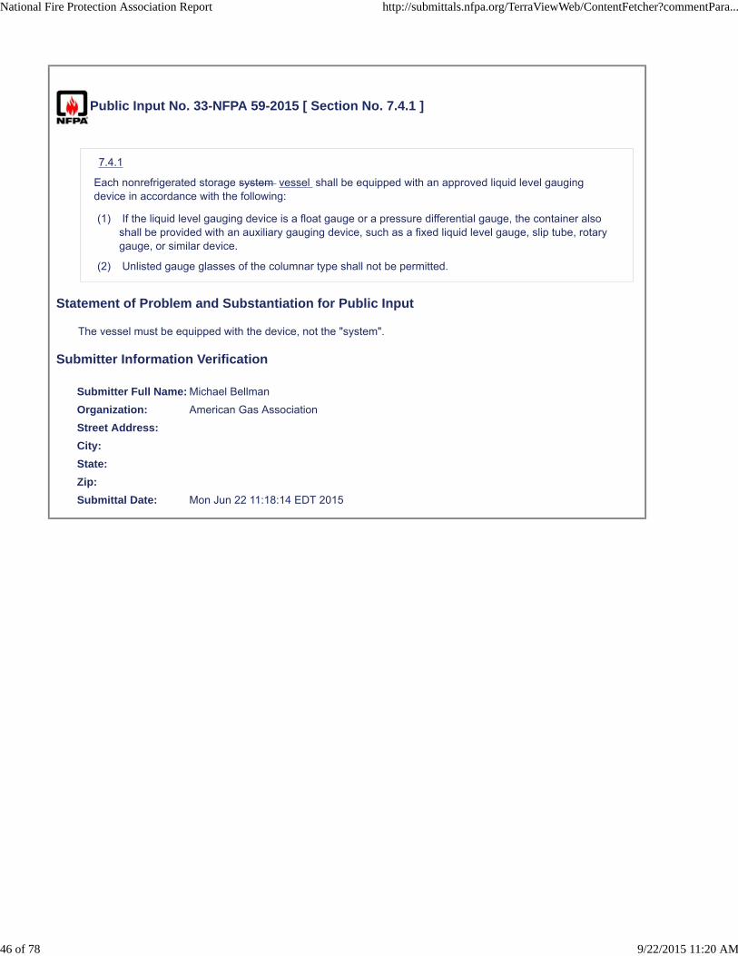
Public Input No. 33-NFPA 59-2015 [ Section No. 7.4.1 ]
7.4.1
Each nonrefrigerated storage system vessel shall be equipped with an approved liquid level gaugingdevice in accordance with the following:
(1) If the liquid level gauging device is a float gauge or a pressure differential gauge, the container alsoshall be provided with an auxiliary gauging device, such as a fixed liquid level gauge, slip tube, rotarygauge, or similar device.
(2) Unlisted gauge glasses of the columnar type shall not be permitted.
Statement of Problem and Substantiation for Public Input
The vessel must be equipped with the device, not the "system".
Submitter Information Verification
Submitter Full Name: Michael Bellman
Organization: American Gas Association
Street Address:
City:
State:
Zip:
Submittal Date: Mon Jun 22 11:18:14 EDT 2015
National Fire Protection Association Report http://submittals.nfpa.org/TerraViewWeb/ContentFetcher?commentPara...
46 of 78 9/22/2015 11:20 AM

Public Input No. 34-NFPA 59-2015 [ Section No. 7.4.3 ]
7.4.3
Gauging devices that require bleeding of the product to the atmosphere, such as the rotary tube, fixed liquidlevel gauge, and slip tube, shall be designed so that the bleed valve maximum opening is not larger than aNo. 54 drill size 0.055 inch diamter , unless provided with an excess-flow valve.
Statement of Problem and Substantiation for Public Input
This change will provide a more universally understood dimensioning.
Submitter Information Verification
Submitter Full Name: Michael Bellman
Organization: American Gas Association
Street Address:
City:
State:
Zip:
Submittal Date: Mon Jun 22 11:20:11 EDT 2015
National Fire Protection Association Report http://submittals.nfpa.org/TerraViewWeb/ContentFetcher?commentPara...
47 of 78 9/22/2015 11:20 AM

Public Input No. 35-NFPA 59-2015 [ Section No. 7.8.1 ]
7.8.1
Refrigerated storage systems Refrigeration facilities shall be provided with sufficient capacity to maintaincontainers at a pressure not in excess of the operating pressure under design ambient conditions where thetank is sited and shall be provided with additional capacity for filling or standby service.
Statement of Problem and Substantiation for Public Input
Refrigeration facility is a better use of the Component- Facility- Plant hierarchy and retains consistency throughout the standard.
Related Public Inputs for This Document
Related Input Relationship
Public Input No. 20-NFPA 59-2015 [New Section after 3.3.11.2]
Submitter Information Verification
Submitter Full Name: Michael Bellman
Organization: American Gas Association
Street Address:
City:
State:
Zip:
Submittal Date: Mon Jun 22 11:23:58 EDT 2015
National Fire Protection Association Report http://submittals.nfpa.org/TerraViewWeb/ContentFetcher?commentPara...
48 of 78 9/22/2015 11:20 AM

Public Input No. 26-NFPA 59-2015 [ New Section after 7.8.5 ]
7.9 * Process pressure vessels shall be designed and fabricated in accordance with the ASME Boiler and PressureVessel Code, Section VIII, Division 1, or Division 2, or with the CSA B51, Boiler Pressure Vessel and Piping Code, andshall be code-stamped
Statement of Problem and Substantiation for Public Input
The additional recognition of process pressure vessels that may be used and are not storage containers by definition should be identified, defined along with their design, and fabrication requirements in the ASME BPVC. Additionally, an asterisk have been added to indicate new annex information to be included in a separate P.I.
Related Public Inputs for This Document
Related Input Relationship
Public Input No. 25-NFPA 59-2015 [Chapter 7 [Title Only]]
Submitter Information Verification
Submitter Full Name: Michael Bellman
Organization: American Gas Association
Street Address:
City:
State:
Zip:
Submittal Date: Mon Jun 22 10:58:26 EDT 2015
National Fire Protection Association Report http://submittals.nfpa.org/TerraViewWeb/ContentFetcher?commentPara...
49 of 78 9/22/2015 11:20 AM

Public Input No. 36-NFPA 59-2015 [ Section No. 7.10.4.3 ]
7.10.4.3 *
The emergency shutoff valve(s) or backflow check valve(s) specified in 7.10.4.1 shall be installed in theplant facility piping so that any break resulting from a pull will occur on the hose or swivel-type piping sideof the connection while retaining intact the valves and piping on the plant facility side of the connection.
Exception: Such anchorage shall not be required for the tank car side.
Statement of Problem and Substantiation for Public Input
Facility is more appropriate, and retains the Component-Facility- Plant hierarchy
Related Public Inputs for This Document
Related Input Relationship
Public Input No. 20-NFPA 59-2015 [New Section after 3.3.11.2]
Submitter Information Verification
Submitter Full Name: Michael Bellman
Organization: American Gas Association
Street Address:
City:
State:
Zip:
Submittal Date: Mon Jun 22 11:57:26 EDT 2015
National Fire Protection Association Report http://submittals.nfpa.org/TerraViewWeb/ContentFetcher?commentPara...
50 of 78 9/22/2015 11:20 AM

Public Input No. 37-NFPA 59-2015 [ Section No. 7.10.4.4 ]
7.10.4.4
All new installations and, by December 31, 2005, all existing installations and existing installations shallhave at least two clearly identified and easily accessible manually operated remote emergency shutoffdevices. One shutoff device shall be located not less than 20 ft (6.1 m) nor more than 100 ft (30.5 m) in thepath of egress from the emergency shutoff valve.
Statement of Problem and Substantiation for Public Input
Date has passed and is no longer needed – removal will add clarity to the code.
Submitter Information Verification
Submitter Full Name: Michael Bellman
Organization: American Gas Association
Street Address:
City:
State:
Zip:
Submittal Date: Mon Jun 22 12:01:15 EDT 2015
National Fire Protection Association Report http://submittals.nfpa.org/TerraViewWeb/ContentFetcher?commentPara...
51 of 78 9/22/2015 11:20 AM
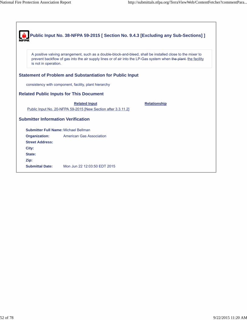
Public Input No. 38-NFPA 59-2015 [ Section No. 9.4.3 [Excluding any Sub-Sections] ]
A positive valving arrangement, such as a double-block-and-bleed, shall be installed close to the mixer toprevent backflow of gas into the air supply lines or of air into the LP-Gas system when the plant the facilityis not in operation.
Statement of Problem and Substantiation for Public Input
consistency with component, facility, plant hierarchy
Related Public Inputs for This Document
Related Input Relationship
Public Input No. 20-NFPA 59-2015 [New Section after 3.3.11.2]
Submitter Information Verification
Submitter Full Name: Michael Bellman
Organization: American Gas Association
Street Address:
City:
State:
Zip:
Submittal Date: Mon Jun 22 12:03:50 EDT 2015
National Fire Protection Association Report http://submittals.nfpa.org/TerraViewWeb/ContentFetcher?commentPara...
52 of 78 9/22/2015 11:20 AM

Public Input No. 39-NFPA 59-2015 [ Section No. 9.5.1.3 ]
9.5.1.3
If the heat source serving heat supplying device serving an indirect vaporizer utilizes a noncombustibleheat transfer fluid, such as steam, water, or a water–glycol mixture, it shall be is installed outdoors orshall comply with one of the following: If installed within a structure , the structure shall comply withChapter 8. If installed outdoors, the heat-supplying device or the housing in which it is installed shall belocated at least 50 ft ( 15 m 15m ) from other LP-Gas facilities and operations , or shall comply with one ofthe following:
(1) If installed within a structure, the structure shall comply with Chapter 8 .
(2) .
(3) If the heat source of an indirect vaporizer is gas fired and is located within 15 ft (4.6 m) of thevaporizer, the vaporizer and its heat source shall be installed as a direct-fired vaporizer and shall besubject to the requirements of 9.5.2 .
(4) A source of heat for an indirect vaporizer shall be permitted to be installed in an industrial occupancycomplying with Chapter 40 of NFPA 101 , Life Safety Code , and Section 9.3 of NFPA 54, NationalFuel Gas Code , where the heat transfer fluid is steam or hot water and is not recirculated and abackflow preventer is installed between the vaporizer and the heat source.
(5) If the heat transfer fluid is recirculated after leaving the vaporizer, a phase separator shall beinstalled with the gas vented to a safe location.
Statement of Problem and Substantiation for Public Input
Deleting 9.5.1.3 (2), and incorporating the text in with the requirements for outside installations is grammatically correct and adds clarity
Submitter Information Verification
Submitter Full Name: Michael Bellman
Organization: American Gas Association
Street Address:
City:
State:
Zip:
Submittal Date: Mon Jun 22 12:12:51 EDT 2015
National Fire Protection Association Report http://submittals.nfpa.org/TerraViewWeb/ContentFetcher?commentPara...
53 of 78 9/22/2015 11:20 AM
Public Input No. 62-NFPA 59-2015 [ Section No. 9.5.2.4 ]
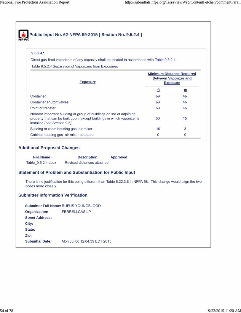
9.5.2.4*
Direct gas-fired vaporizers of any capacity shall be located in accordance with Table 9.5.2.4.
Table 9.5.2.4 Separation of Vaporizers from Exposures
Exposure
Minimum Distance RequiredBetween Vaporizer and
Exposure
ft m
Container 50 15
Container shutoff valves 50 15
Point of transfer 50 15
Nearest important building or group of buildings or line of adjoiningproperty that can be built upon [except buildings in which vaporizer isinstalled (see Section 9.5)]
50 15
Building or room housing gas–air mixer 10 3
Cabinet housing gas–air mixer outdoors 0 0
Additional Proposed Changes
File Name Description Approved
Table_9.5.2.4.docx Revised distances attached
Statement of Problem and Substantiation for Public Input
There is no justification for this being different than Table 6.22.3.6 in NFPA 58. This change would align the two codes more closely.
Submitter Information Verification
Submitter Full Name: RUFUS YOUNGBLOOD
Organization: FERRELLGAS LP
Street Address:
City:
State:
Zip:
Submittal Date: Mon Jul 06 12:04:39 EDT 2015
National Fire Protection Association Report http://submittals.nfpa.org/TerraViewWeb/ContentFetcher?commentPara...
54 of 78 9/22/2015 11:20 AM
Public Input No. 63-NFPA 59-2015 [ Section No. 10.1.4 ]
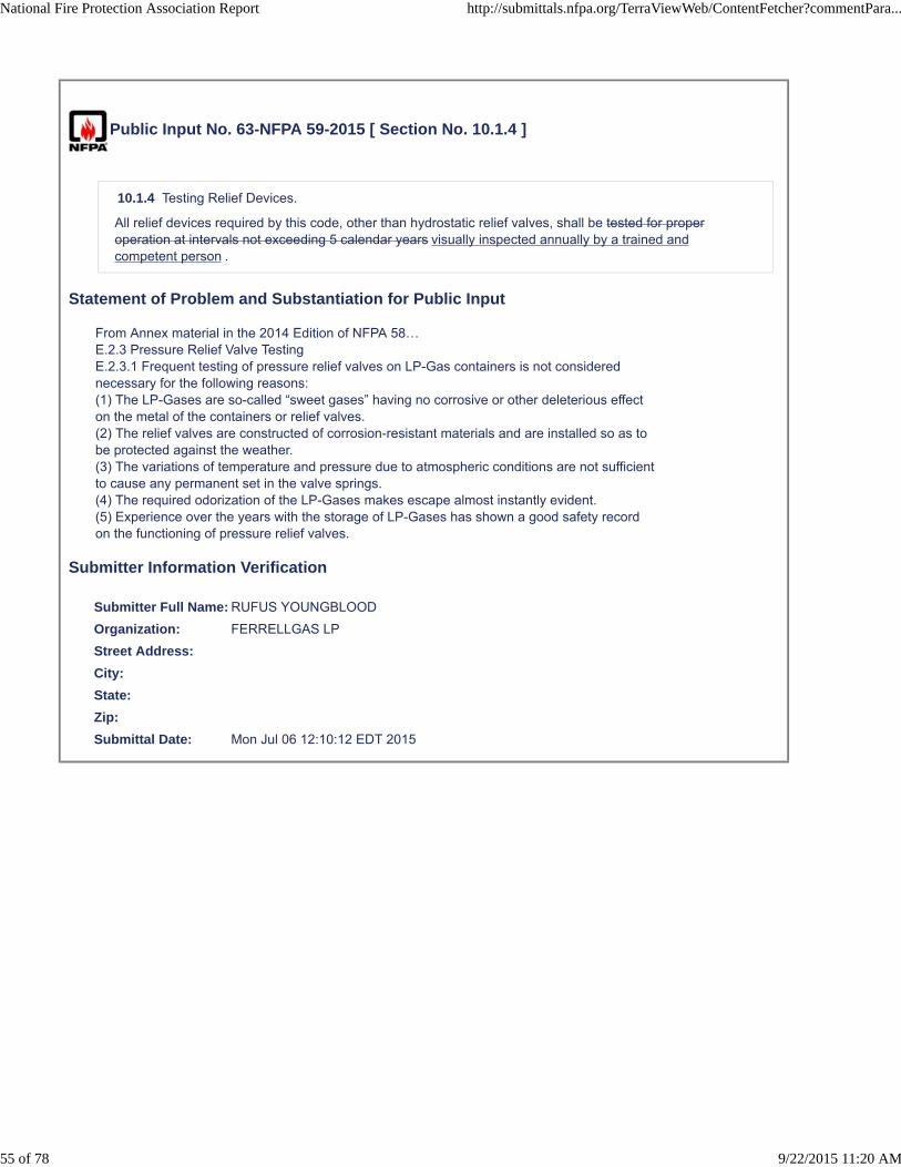
10.1.4 Testing Relief Devices.
All relief devices required by this code, other than hydrostatic relief valves, shall be tested for properoperation at intervals not exceeding 5 calendar years visually inspected annually by a trained andcompetent person .
Statement of Problem and Substantiation for Public Input
From Annex material in the 2014 Edition of NFPA 58…E.2.3 Pressure Relief Valve TestingE.2.3.1 Frequent testing of pressure relief valves on LP-Gas containers is not considerednecessary for the following reasons:(1) The LP-Gases are so-called “sweet gases” having no corrosive or other deleterious effecton the metal of the containers or relief valves.(2) The relief valves are constructed of corrosion-resistant materials and are installed so as tobe protected against the weather.(3) The variations of temperature and pressure due to atmospheric conditions are not sufficientto cause any permanent set in the valve springs.(4) The required odorization of the LP-Gases makes escape almost instantly evident.(5) Experience over the years with the storage of LP-Gases has shown a good safety recordon the functioning of pressure relief valves.
Submitter Information Verification
Submitter Full Name: RUFUS YOUNGBLOOD
Organization: FERRELLGAS LP
Street Address:
City:
State:
Zip:
Submittal Date: Mon Jul 06 12:10:12 EDT 2015
National Fire Protection Association Report http://submittals.nfpa.org/TerraViewWeb/ContentFetcher?commentPara...
55 of 78 9/22/2015 11:20 AM

Public Input No. 40-NFPA 59-2015 [ Section No. 11.2.1 ]
11.2.1
Operating procedures manuals shall include operator actions to be taken if flammable concentrations offlammable liquids or gases are detected in the facility using the following:
(1) Fixed detectors
(2) Portable detectors
(3) Operating malfunctions
(4) Human senses
Statement of Problem and Substantiation for Public Input
Operating malfunctions are not an appropriate means for the detection of flammable liquids or gases. While leaks may be found after a malfunction, this reference is not appropriate for the intent of the statement.
Submitter Information Verification
Submitter Full Name: Michael Bellman
Organization: American Gas Association
Street Address:
City:
State:
Zip:
Submittal Date: Mon Jun 22 12:17:34 EDT 2015
National Fire Protection Association Report http://submittals.nfpa.org/TerraViewWeb/ContentFetcher?commentPara...
56 of 78 9/22/2015 11:20 AM

Public Input No. 41-NFPA 59-2015 [ Section No. 12.3.6.1 ]
12.3.6.1
Cathodic protection of buried or submerged components shall comply with the following:
(1) Cathodic protection systems installed in accordance with 12.3.3 shall be monitored by testing and theresults documented and retained per 12.10.2(3).
(2)
(3)
(4)
Producing a voltage of −0.78 volts or more negative, with reference to saturated KCl calomel half cell.
(a)
(b)
(5) Each buried or submerged component under cathodic protection shall be tested by personnelqualified to perform corrosion control monitoring at least once each calendar year, with intervals notexceeding 15 months, to determine whether the cathodic protection is performing as designed.
(6) Each cathodic protection rectifier or other impressed current power source shall be inspected bypersonnel qualified to perform corrosion control monitoring at least six times each calendar year, withintervals not exceeding 2 1⁄2 months, to ensure that it is performing as designed.
(7) Each reverse current switch, each diode, and each interference bond whose failure would jeopardizecomponent protection shall be electrically checked for proper performance at least six times eachcalendar year, with intervals not exceeding 2 1⁄2 months, by personnel qualified to perform corrosioncontrol monitoring. Each other interference bond shall be checked at least once each calendar year,with intervals not exceeding 15 months.
(8) Whenever any portion of a buried pipe is exposed, the exposed portion of the pipe shall be examinedfor evidence of external corrosion in either of the following instances:
(9) If general external or localized external pitting corrosion is identified, additional examination inthe exposed area is necessary to identify the extent of the corrosion.
(10) If damage to the component coating is observed, the coating shall be repaired in accordancewith 12.3.3.1.1.2 .
Statement of Problem and Substantiation for Public Input
deleting repetitive wording
Submitter Information Verification
Submitter Full Name: Michael Bellman
Organization: American Gas Association
Street Address:
City:
State:
* Cathodic protection system tests shall be described by one of the following:
Producing a voltage of −0.85 volts or more negative, with reference to a saturated copper–copper sulfate half cell.
* Producing a voltage of −0.78 volts or more negative, with reference to saturated KCl calomelhalf cell.
Producing a voltage of −0.80 volts or more negative, with reference to a silver–silver chloridehalf cell.
National Fire Protection Association Report http://submittals.nfpa.org/TerraViewWeb/ContentFetcher?commentPara...
57 of 78 9/22/2015 11:20 AM

Zip:
Submittal Date: Mon Jun 22 12:20:12 EDT 2015
National Fire Protection Association Report http://submittals.nfpa.org/TerraViewWeb/ContentFetcher?commentPara...
58 of 78 9/22/2015 11:20 AM
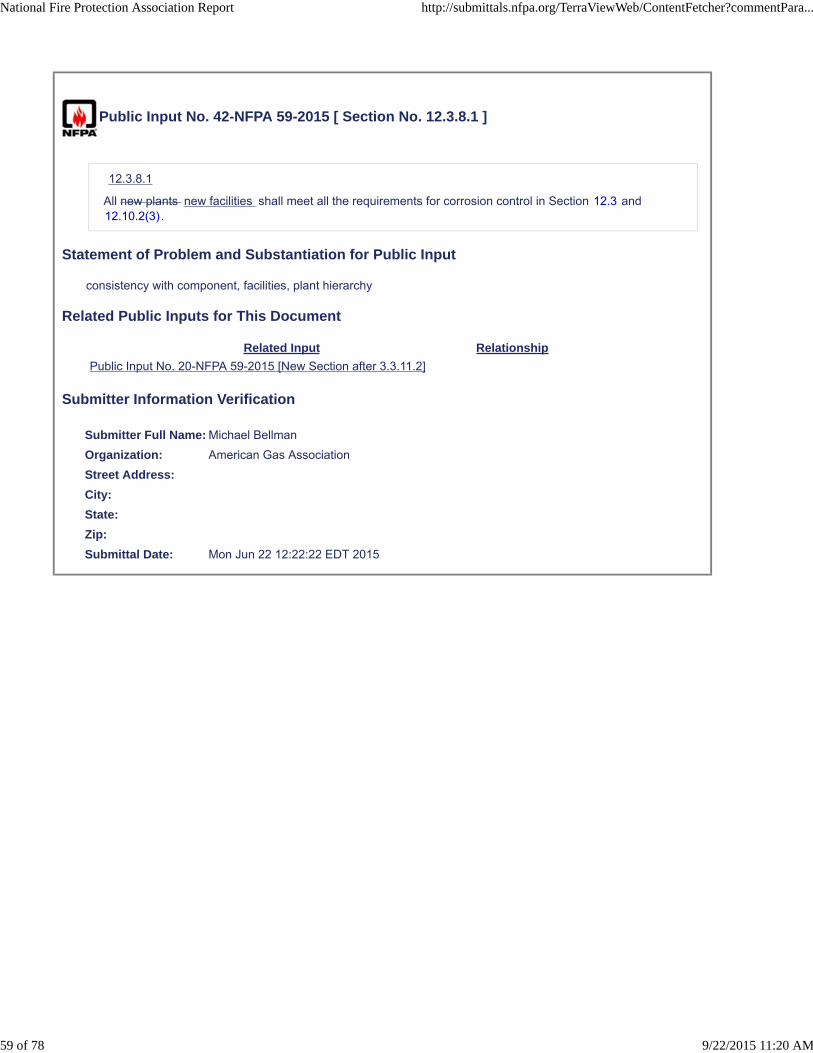
Public Input No. 42-NFPA 59-2015 [ Section No. 12.3.8.1 ]
12.3.8.1
All new plants new facilities shall meet all the requirements for corrosion control in Section 12.3 and12.10.2(3).
Statement of Problem and Substantiation for Public Input
consistency with component, facilities, plant hierarchy
Related Public Inputs for This Document
Related Input Relationship
Public Input No. 20-NFPA 59-2015 [New Section after 3.3.11.2]
Submitter Information Verification
Submitter Full Name: Michael Bellman
Organization: American Gas Association
Street Address:
City:
State:
Zip:
Submittal Date: Mon Jun 22 12:22:22 EDT 2015
National Fire Protection Association Report http://submittals.nfpa.org/TerraViewWeb/ContentFetcher?commentPara...
59 of 78 9/22/2015 11:20 AM

Public Input No. 43-NFPA 59-2015 [ New Section after 12.7 ]
12.6.1 Maintenance of fire protection systems shall be in accordance with requirements in fire protectionstandards identified in Chapter 13.
Statement of Problem and Substantiation for Public Input
New 12.6.1 clarifies that maintenance requirements for fire protection systems are located in chapter 13 and the standards identified in chapter 13.
Submitter Information Verification
Submitter Full Name: Michael Bellman
Organization: American Gas Association
Street Address:
City:
State:
Zip:
Submittal Date: Mon Jun 22 12:24:41 EDT 2015
National Fire Protection Association Report http://submittals.nfpa.org/TerraViewWeb/ContentFetcher?commentPara...
60 of 78 9/22/2015 11:20 AM

Public Input No. 48-NFPA 59-2015 [ Section No. 13.1.1 [Excluding any Sub-Sections] ]
Fire protection shall be provided for all utility gas plants LP-Gas facilities .
Statement of Problem and Substantiation for Public Input
consistency with component, facility, plant hierarchy
Related Public Inputs for This Document
Related Input Relationship
Public Input No. 20-NFPA 59-2015 [New Section after 3.3.11.2]
Submitter Information Verification
Submitter Full Name: Michael Bellman
Organization: American Gas Association
Street Address:
City:
State:
Zip:
Submittal Date: Mon Jun 22 12:43:18 EDT 2015
National Fire Protection Association Report http://submittals.nfpa.org/TerraViewWeb/ContentFetcher?commentPara...
61 of 78 9/22/2015 11:20 AM

Public Input No. 44-NFPA 59-2015 [ New Section after 13.1.1.3 ]
13.1.1.3
Fire protection systems installed as a result of the evaluation in 13.1.1.1 and 13.1.1.2 shall be designed,engineered, installed , tested, and maintained based upon fire protection equipment standards identifiedand incorporated by reference within this standard .
Statement of Problem and Substantiation for Public Input
The PI is recommended to be inserted ahead of 13.1.1.3 and renumber remaining 13.1.1. This PI further clarifies that where fire protection is installed, the requirements for design, engineering, installation, testing, and maintenance of fire protection systems must adhere to identified and incorporated by reference fire protect system standards. This PI aligns with similar requirements in the LNG standard NFPA 59A.
Submitter Information Verification
Submitter Full Name: Michael Bellman
Organization: American Gas Association
Street Address:
City:
State:
Zip:
Submittal Date: Mon Jun 22 12:29:40 EDT 2015
National Fire Protection Association Report http://submittals.nfpa.org/TerraViewWeb/ContentFetcher?commentPara...
62 of 78 9/22/2015 11:20 AM

Public Input No. 45-NFPA 59-2015 [ Section No. 13.2 ]
13.2 Gas, Fire and Leak Detection.
13.2.1
Those areas, including enclosed buildings, that have a potential for flammable gas concentrations and fireshall be monitored as determined by the evaluation required in 13.1.1.
13.2.2
Continuously monitored flammable gas detection systems or low temperature sensors used for leakdetection purposes shall alarm at the plant site and at a constantly attended location if the plant site is notcontinuously manned.
13.2.3
Flammable gas detection systems shall alarm at not more than 25 percent of the lower flammable limit ofthe gas or vapor being monitored.
13.2.4 *
Fire detectors shall alarm at the plant site and at a constantly attended location if the plant site is notcontinually manned.
13.2.5
Where installed as determined by the evaluation required in 13.1.1, the following fire alarm componentsshall be designed, installed, documented, tested, and maintained in accordance with NFPA 72, NationalFire Alarm and Signaling Code:
(1) Initiating devices (detectors — smoke, flame, heat, etc.)
(2) Fire system monitor panels
(3) Notification appliances (strobes, sirens, etc.)
(4) Fire system activation devices on installed extinguishment/suppression systems (water deluge, fixeddry chemical systems)
(5) Field wiring between initiating, notification components, activation/suppression system, and controlpanels
(6) Power supply and backup power equipment for fire alarm system
Statement of Problem and Substantiation for Public Input
The recognition of low temperature detection in 13.2 to compliment gas detection at facilities handling refrigerated LPG is appropriate and aligns with similar actions taken by the NFPA 59A TC at the last second draft meeting.
Related Public Inputs for This Document
Related Input Relationship
Public Input No. 46-NFPA 59-2015 [New Section after 13.2.3]
Submitter Information Verification
Submitter Full Name: Michael Bellman
Organization: American Gas Association
Street Address:
City:
State:
National Fire Protection Association Report http://submittals.nfpa.org/TerraViewWeb/ContentFetcher?commentPara...
63 of 78 9/22/2015 11:20 AM

Zip:
Submittal Date: Mon Jun 22 12:34:19 EDT 2015
National Fire Protection Association Report http://submittals.nfpa.org/TerraViewWeb/ContentFetcher?commentPara...
64 of 78 9/22/2015 11:20 AM

Public Input No. 46-NFPA 59-2015 [ New Section after 13.2.3 ]
13.2.2.1 *Where utilized, leak detection should be used to compliment fire and gas detection and is not intendedto replace fire and gas detection
Statement of Problem and Substantiation for Public Input
The recognition of low temperature detection in 13.2 to compliment gas detection at facilities handling refrigerated LPG is appropriate and aligns with similar actions taken by the NFPA 59A TC at the last second draft meeting. The annex text recommended provides users examples of low temperature and systems that might be used to enhance gas detection
Related Public Inputs for This Document
Related Input Relationship
Public Input No. 45-NFPA 59-2015 [Section No. 13.2]
Public Input No. 47-NFPA 59-2015 [New Section after A.13.2.4]
Submitter Information Verification
Submitter Full Name: Michael Bellman
Organization: American Gas Association
Street Address:
City:
State:
Zip:
Submittal Date: Mon Jun 22 12:38:27 EDT 2015
National Fire Protection Association Report http://submittals.nfpa.org/TerraViewWeb/ContentFetcher?commentPara...
65 of 78 9/22/2015 11:20 AM

Public Input No. 49-NFPA 59-2015 [ Section No. 13.4.4 ]
13.4.4
Fire protection water systems, where used, shall be designed, installed, and maintained in accordance withthe following NFPA standards, as applicable, considering the fire control problems in facilities covered bythis standard:
(1) NFPA 13, Standard for the Installation of Sprinkler Systems
(2) NFPA 14, Standard for the Installation of Standpipe and Hose Systems
(3) NFPA 15, Standard for Water Spray Fixed Systems for Fire Protection
(4) NFPA 20, Standard for the Installation of Stationary Pumps for Fire Protection
(5) NFPA 22, Standard for Water Tanks for Private Fire Protection
(6) NFPA 24, Standard for the Installation of Private Fire Service Mains and Their Appurtenances
(7) NFPA 25, Standard for the Inspection, Testing, and Maintenance of Water-Based Fire ProtectionSystems
(8) NFPA 1961, Standard on Fire Hose
(9) NFPA 1962, Standard for the Care, Use, Inspection, Service Testing, and Replacement of Fire Hose,Coupling, Nozzles, and Fire Hose Appliances.
(10) NFPA 1963, Standard for Fire Hose Connections
Statement of Problem and Substantiation for Public Input
The recognition of NFPA 25 identifies maintenance requirements for water based fire protections as the maintenance requirements were removed from the specific water based system standards (NFPA 13, 14, 15, 20, 22, 24, etc) and relocated in NFPA 25 over 10 years ago. The recognition of NFPA 25 in this standard is necessary and aligns with changes being made in the LNG standard NFPA 59A
Related Public Inputs for This Document
Related Input Relationship
Public Input No. 50-NFPA 59-2015 [Section No. 13.5.3]
Submitter Information Verification
Submitter Full Name: Michael Bellman
Organization: American Gas Association
Street Address:
City:
State:
Zip:
Submittal Date: Mon Jun 22 12:47:42 EDT 2015
National Fire Protection Association Report http://submittals.nfpa.org/TerraViewWeb/ContentFetcher?commentPara...
66 of 78 9/22/2015 11:20 AM

Public Input No. 8-NFPA 59-2015 [ Section No. 13.5.1.1 ]
13.5.1.1
The minimum size portable dry chemical extinguisher for gas fires shall be 18 lb (8.2 kg) with a B:Crating rated 60-B:C.
A.13.5.1.1 In areas containing common combustibles (Class A fires), a dry chemical extinguisher with arating of 4-A:60-B:C would satisfy this requirement and could also satsfy the need for extinguishers forClass A fires .
Statement of Problem and Substantiation for Public Input
A typical 20 lb BC dry chemical extinguisher has a rating of 60-B:C. The minimum requirement should state the extinguisher rating, which relates to the listed fire fighting capacity. The minimum size portable dry chemical extinguisher for gas fires should therefore be rated 60-B:C. In areas where there are also common combustibles, a dry chemical extinguisher with a rating of 4-A:60-B:C would satisfy the need for protection of both Class A and Class B.
Submitter Information Verification
Submitter Full Name: Jennifer Boyle
Organization: Mark Conroy, Brooks Equipment Company
Affilliation: Fire Equipment Manufacturers Association
Street Address:
City:
State:
Zip:
Submittal Date: Fri May 22 11:33:03 EDT 2015
National Fire Protection Association Report http://submittals.nfpa.org/TerraViewWeb/ContentFetcher?commentPara...
67 of 78 9/22/2015 11:20 AM

Public Input No. 50-NFPA 59-2015 [ Section No. 13.5.3 ]
13.5.3
Where fixed fire-extinguishing and other fire control systems are provided, such systems shall be designed,installed, and maintained in accordance with the following NFPA standards, as applicable:
(1) NFPA 10, Standard for Portable Fire Extinguishers
(2) NFPA 11, Standard for Low-, Medium-, and High-Expansion Foam
(3) NFPA 12, Standard on Carbon Dioxide Extinguishing Systems
(4) NFPA 12A, Standard on Halon 1301 Fire Extinguishing Systems
(5) NFPA 16, Standard for the Installation of Foam-Water Sprinkler and Foam-Water Spray Systems
(6) NFPA 17, Standard for Dry Chemical Extinguishing Systems
(7)
(8) NFPA
25, Standard for the Inspection, Testing, and Maintenance of Water-Based Fire Protection Systems
(9) NFPA 2001, Standard on Clean Agent Fire Extinguishing Systems
Statement of Problem and Substantiation for Public Input
NFPA 25 is a maintenance standard for water based fire protection systems and has been recommended for placement in 13.4.4 in a separate P.I
Related Public Inputs for This Document
Related Input Relationship
Public Input No. 49-NFPA 59-2015 [Section No. 13.4.4]
Submitter Information Verification
Submitter Full Name: Michael Bellman
Organization: American Gas Association
Street Address:
City:
State:
Zip:
Submittal Date: Mon Jun 22 12:50:53 EDT 2015
National Fire Protection Association Report http://submittals.nfpa.org/TerraViewWeb/ContentFetcher?commentPara...
68 of 78 9/22/2015 11:20 AM

Public Input No. 51-NFPA 59-2015 [ Section No. 13.6 ]
13.6 Maintenance of Fire Protection Equipment.
Facility operators shall prepare and implement a maintenance program for all plant fire protectionequipment.
Statement of Problem and Substantiation for Public Input
Unnecessary modifier to the word Operator
Submitter Information Verification
Submitter Full Name: Michael Bellman
Organization: American Gas Association
Street Address:
City:
State:
Zip:
Submittal Date: Mon Jun 22 12:53:08 EDT 2015
National Fire Protection Association Report http://submittals.nfpa.org/TerraViewWeb/ContentFetcher?commentPara...
69 of 78 9/22/2015 11:20 AM

Public Input No. 52-NFPA 59-2015 [ Section No. 13.8.2.3 ]
13.8.2.3
Such devices, when in place, shall prevent unauthorized operation of any of the container appurtenances,system facility valves, or equipment.
Statement of Problem and Substantiation for Public Input
consistency component, facility, plant heirarchy
Related Public Inputs for This Document
Related Input Relationship
Public Input No. 20-NFPA 59-2015 [New Section after 3.3.11.2]
Submitter Information Verification
Submitter Full Name: Michael Bellman
Organization: American Gas Association
Street Address:
City:
State:
Zip:
Submittal Date: Mon Jun 22 12:55:49 EDT 2015
National Fire Protection Association Report http://submittals.nfpa.org/TerraViewWeb/ContentFetcher?commentPara...
70 of 78 9/22/2015 11:20 AM

Public Input No. 53-NFPA 59-2015 [ New Section after A.4.5.2.2 ]
A.4.5.2.2 When classifying the extent of an entire facility or a specific portion of the facility, considerationshould be given to increasing the extent of the hazardous area location above those stated in the NEC andNFPA 59 Table 4.5.2.2 based on higher flow rates and pressures utilized within larger facilities. Additionalguidance for extending electrical area classifications can be found in NFPA 497 Electrical Installations inChemical Atmospheres Involving Flammable Liquids, Gases, or Vapors.
Statement of Problem and Substantiation for Public Input
The additional annex material aids users of the standard who design/engineering/construct propane facilities as well as those who own/operate these facilities that facilities operating at higher flows/pressure are at higher risk than the smaller facilities with lower flows and pressures and that consideration for possible extension of the traditional hazardous area classification area values
Submitter Information Verification
Submitter Full Name: Michael Bellman
Organization: American Gas Association
Street Address:
City:
State:
Zip:
Submittal Date: Mon Jun 22 12:59:55 EDT 2015
National Fire Protection Association Report http://submittals.nfpa.org/TerraViewWeb/ContentFetcher?commentPara...
71 of 78 9/22/2015 11:20 AM

Public Input No. 54-NFPA 59-2015 [ New Section after A.7.4.5 ]
A.7.9 In the United States, the Pipeline Hazardous Materials Safety Administration (PHMSA) incorporatesby reference in 49 CFR Part 192 the ASME Boiler and Pressure Vessel Code Section VIII Division 1. Thecurrent version of the ASME BPVC Section VIII at the time this NFPA Standard was issued requires testingat only 1.3 times the MAWP. PHMSA in a March 2015 Final Rule requires in 192.153 the componentsfabricated by welding (other than branch connections or assemblies of standard pipe) under ASME BPVC(Boiler Pressure Vessel Code) Section VIII, Division 1, or 2 be subject to strength testing to at least 1.5 timesthe MAOP regardless of the conflict. Owner, operators installing new equipment should gain the approval ofthe AHJ if testing at 1.3 vs. 1.5 times the MAWP.
Statement of Problem and Substantiation for Public Input
Proposed annex material identifies conflicts in testing of new vessels, boilers, etc. between current and earlier edition of the ASME BPVC which can present substantial difficulties in purchasing of this equipment from certified manufacturers. The proposed annex material aides owner/operators ensure AHJ requirements are met.
Submitter Information Verification
Submitter Full Name: Michael Bellman
Organization: American Gas Association
Street Address:
City:
State:
Zip:
Submittal Date: Mon Jun 22 13:02:49 EDT 2015
National Fire Protection Association Report http://submittals.nfpa.org/TerraViewWeb/ContentFetcher?commentPara...
72 of 78 9/22/2015 11:20 AM

Public Input No. 55-NFPA 59-2015 [ Sections A.10.1, A.11.2.3 ]
Sections A.10.1, A.11.2.3
A.10.1
Experience has indicated that a vertical for safety relief valves in vapor service only and those that emit amist, vertical and unimpeded vent of high-velocity hydrocarbon gases will entrain sufficient air within a veryshort distance so that the resultant plume will be diluted below the lower flammable limit. This behavior isdocumented in ANSI/API 521, Guide for Pressure-Relieving and Depressuring Systems. This documentwas based, in part, on an API-commissioned study by Battelle Memorial Institute, “The Effect of Velocity,Temperature, and Gas Molecular Weight on Flammability Limits in Wind-Blown Jets of HydrocarbonGases.”
These reports clearly indicate that a vertical and unimpeded jet from a safety relief valve in vapor serviceonly and those that emit a mist will be diluted below its lower flammable limit within 50 pipe diameters ofthe issuing jet and that the effects of “wind-tilt” can be safely neglected if a 50 ft (15 m) horizontal clearanceis provided between the jet and a source of ignition. A high velocity jet is defined as a jet having an exitvelocity in excess of 100 ft/sec (30.5 m/sec), which is slightly more than an order of magnitude less than theacoustic velocity that can be anticipated at the throat of an operating relief valve. ANSI/API 521 alsoindicates that a partially open relief valve in vapor service will produce a velocity sufficient to achieve thenecessary dilution.
Once such a mixture from a safety relief valve in vapor service only and those that emit a mist has beendiluted below its flammable limit, there are no known natural forces (including gravitational forces) that willcause the reconcentration of the LP-Gases so as to create a flammable cloud. The application of water, aseither a fog or a heavy stream, will not hasten and can actually inhibit the dilution of the jet stream. It isrecommended that this information be included in any emergency procedure manual and that theresponding emergency services be made aware of this information.
Based on information in API 521, safety relieve valves that are in liquid service when relieving donot entrain sufficient volumes of air to dilute the mixture to below LEL levels. Additional considerationsshould be considered when establishing the electrical area classification and classification distancesnear relief valves in liquid service.
A.11.2.3
For information on purging and inerting equipment, see NFPA 326, Standard for the Safeguarding of Tanksand Containers for Entry, Cleaning, or Repair, and AGA Purging Principles and Practice.
Statement of Problem and Substantiation for Public Input
The rationale for not identifying an electrical area classification near safety relief valves has been based on the annex information in A.10.1 that states based on details in API 521 6.3.2.2, (2007 edition w/May 2008 Addendum) that during the discharge from a safety relief valve that the discharge velocity is such that sufficient volumes of air is entrained in the discharge stream and therefor dilutes the mixture to below the LEL. While this is stated in API 521, it is only applicable to safety relief valves discharging vapor. API 521 6.3.2.3, and 6.3.2.4 additionally describes the discharges of mists and liquids and goes onto state that the same air entrainment activity is not expected to occur for liquid service valves and flammable concentrations in the area near the valves should be further evaluated. Safety relief valves in NFPA 59 facilities can be either in vapor or liquid service and for this reason the table has been changed to reflect the minimum hazardous area classifications.
Related Public Inputs for This Document
Related Input Relationship
Public Input No. 57-NFPA 59-2015 [Section No. 4.5.2.2]
Submitter Information Verification
National Fire Protection Association Report http://submittals.nfpa.org/TerraViewWeb/ContentFetcher?commentPara...
73 of 78 9/22/2015 11:20 AM

Submitter Full Name: Michael Bellman
Organization: American Gas Association
Street Address:
City:
State:
Zip:
Submittal Date: Mon Jun 22 13:06:50 EDT 2015
National Fire Protection Association Report http://submittals.nfpa.org/TerraViewWeb/ContentFetcher?commentPara...
74 of 78 9/22/2015 11:20 AM
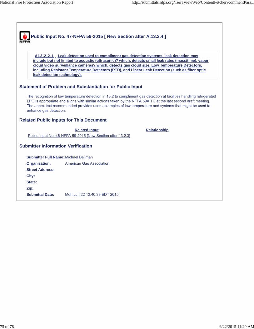
Public Input No. 47-NFPA 59-2015 [ New Section after A.13.2.4 ]
A13.2.2.1 Leak detection used to compliment gas detection systems, leak detection mayinclude but not limited to acoustic (ultrasonic)? which, detects small leak rates (mass/time), vaporcloud video surveillance cameras? which, detects gas cloud size, Low Temperature Detectors,including Resistant Temperature Detectors (RTD), and Linear Leak Detection (such as fiber opticleak detection technology).
Statement of Problem and Substantiation for Public Input
The recognition of low temperature detection in 13.2 to compliment gas detection at facilities handling refrigerated LPG is appropriate and aligns with similar actions taken by the NFPA 59A TC at the last second draft meeting. The annex text recommended provides users examples of low temperature and systems that might be used to enhance gas detection.
Related Public Inputs for This Document
Related Input Relationship
Public Input No. 46-NFPA 59-2015 [New Section after 13.2.3]
Submitter Information Verification
Submitter Full Name: Michael Bellman
Organization: American Gas Association
Street Address:
City:
State:
Zip:
Submittal Date: Mon Jun 22 12:40:39 EDT 2015
National Fire Protection Association Report http://submittals.nfpa.org/TerraViewWeb/ContentFetcher?commentPara...
75 of 78 9/22/2015 11:20 AM

Public Input No. 56-NFPA 59-2015 [ New Section after A.13.2.4 ]
A 13.2.5 Where Fire protection systems are installed in accordance with NFPA 72 and are planned forintegration with other systems, the NFPA 3 Recommended Practice for Commissioning and IntegratedTesting of Fire Protection and Life Safety Systems may be useful in the commissioning and testing of theintegrated systems.
Statement of Problem and Substantiation for Public Input
The additional annex material identifying NFPA 3 provides additional guidance when integrating various fire protection and life systems with other systems.
Submitter Information Verification
Submitter Full Name: Michael Bellman
Organization: American Gas Association
Street Address:
City:
State:
Zip:
Submittal Date: Mon Jun 22 13:13:40 EDT 2015
National Fire Protection Association Report http://submittals.nfpa.org/TerraViewWeb/ContentFetcher?commentPara...
76 of 78 9/22/2015 11:20 AM
Public Input No. 3-NFPA 59-2015 [ Section No. F.1.2 ]
F.1.2 Other Publications.
F.1.2.1 AGA Publications.
American Gas Association, 400 North Capitol Street, NW, Washington, DC 20001.
AGA XH0203, Interchangeability of Other Fuel Gases with Natural Gas, Research Bulletin 36, AGACatalog No. XH0203, 1946 (reprinted 2003). 2002.
Interchangeability — What it Means, AGA Catalog No. XL0884, 2002.
AGA XO9608, Introduction to LPG Safety for Propane Air Plant Operators, AGA Catalog No. XO9608,1996.
AGA XKO101, Purging Principles and Practice, AGA Catalog No. XKO101, 2001. 2001.
F.1.2.2 API Publications.
American Petroleum Institute, 1220 L Street, NW, Washington, DC 20005-4070.
ANSI/ API 521 STD 521 ,Guide for Pressure-Relieving and Depressuring Systems, 2007 6th edition,2014 .
API RP 2003, Protection Against Ignitions Arising out of Static, Lightning, and Stray Currents, 2008edition .
“The Effect of Velocity, Temperature, and Gas Molecular Weight on Flammability Limits in Wind-Blown Jetsof Hydrocarbon Gases,” Battelle Memorial Institute, April 1, 1970.
F.1.2.3 ASME Publications.
American Society of Mechanical Engineers, Three ASME Internationl , Two Park Avenue, New York, NY10016-5990.
ASME Boiler and Pressure Vessel Code, 2007 edition 2015 .
F.1.2.4 NACE Publications.
NACE International 1440 South Creek Drive, , 15835 Park Ten Place , Houston, TX 77084-4906.
SP-01-69 NACE SP0169 , Control of External Corrosion of Underground or Submerged Metallic PipingSystems, 2007 2013 .
SP-0198 NACE SP0198 , Control of Corrosion Under Thermal Insulation and Fireproofing Materials — ASystems Approach, 2010.
SP-02-85 NACE SP0285 , Corrosion Control of Underground Storage Tank Systems by CathodicProtection, 2011.
F.1.2.5 U.S. Government Publications.
U.S. Government Printing Government Publishing Office, Washington, DC 20402.
Title 49, Code of Federal Regulations, Parts 171–190, “Hazardous Materials Regulations.”
Title 49, Code of Federal Regulations, Part 192, “Pipeline Safety Law.”
Statement of Problem and Substantiation for Public Input
References current SDO name, addresses, standard names, numbers, and editions.
Related Public Inputs for This Document
Related Input Relationship
Public Input No. 2-NFPA 59-2015[Section No. 2.3]
Referenced current SDO names, addresses, standard names,numbers, and editions.
National Fire Protection Association Report http://submittals.nfpa.org/TerraViewWeb/ContentFetcher?commentPara...
77 of 78 9/22/2015 11:20 AM
Public Input No. 1-NFPA 59-2015[Global Input]
Submitter Information Verification
Submitter Full Name: Aaron Adamczyk
Organization: [ Not Specified ]
Street Address:
City:
State:
Zip:
Submittal Date: Sat Feb 07 20:22:40 EST 2015
National Fire Protection Association Report http://submittals.nfpa.org/TerraViewWeb/ContentFetcher?commentPara...
78 of 78 9/22/2015 11:20 AM