Embed Size (px)
Citation preview
Cookson And Zinn (PTL) Limited
Design Substantiation of PetroFast Modular Tank Unit
August 2002
(F.E.A. updated 2014)
(Minor update, June 2016) (Minor updates, July 2021)
Cookson And Zinn (PTL) Limited,
Station Road Works,
Pond Hall Lane,
Hadleigh, Ipswich
Suffolk
IP7 5PN
England
Tel 44 (0) 1473 825 200
Fax 44 (0) 1473 824 164
Email: [email protected]
Website: www.czltd.com
FTP: http://secure.czltd.com/Engineering

2
PetroFast - Design Substantiation Introduction
This document covers design verification
for the PetroFast design for 1900, 2500,
2743 & 3000mm diameters, single and
double skin underground tanks. The
tanks form part of a new range of
modular fuel dispensing units which, to
simplify the petrol stations construction
process, are provided with integral
mounting points for connection to the
station’s canopy supports.
The challenge
To simplify/rationalise design &
manufacture, speeding up production,
thus reducing final cost.
Figure 1.0
Take an existing Double-skin steel storage tank, manufactured to the European Standard
EN12285-1:2018, which governs material and construction details of Single & Double-skin
tanks, and attach mounting points which allows the canopy to be bolted to, and
supported from, these points.
Considerations
The adequacy of the inner and outer pressure envelopes of the tanks has been considered
with reference to the European Standard EN 12285-1:2018, while the adequacy of the
canopy supports, and cradle supports have been assessed in accordance with methods
presented in PD.5500 Annex A. For these items, the assessment has been based on the
results obtained from detailed finite element analysis (FEA) of the structure, which has been
carried out using Autodesk Inventor Nastran FEA module. Fatigue life assessment, in
accordance with methods in BS.7608, is included to confirm the longevity of the structure.
The scope of the work has included the derivation of canopy design loads for realistic worst-
case environmental conditions including consideration of the effects of snow, seismic and
wind loadings. A variety of different canopy types and layouts have been considered. Design
loadings thus are intended to cover the likely range of canopies with which the tanks will be
supplied. The effect of impact loads arising from postulated collision between a vehicle and
canopy column is also considered. Although canopy design is excluded from the scope of
work, loads on which the work is based are clearly stated so as to provide design
information for canopy suppliers.
Design loads have been developed with the knowledge of typical canopy designs and on the
understanding that design should be suitable for sites throughout Europe.
Downward Loading (Case 1 & 3)
Canopy load (dead weight) + Snow loading + Seismic + Wind (downdraft) + maximum
contents weight + self-weight + hold-down strap loads.
Upward Loading (Case 2 & 4)
Canopy load (dead weight) + Seismic + Wind (suction) + self-weight + hold-down strap
loads + maximum external pressure.

3
Canopy Support Options
Figure 2.0 Figure 3.0
Load Case 1
As shown in figure 2.0, downward loading, centrally located canopy support, or ‘bridge’.
Load Case 2
As shown in figure 2.0, upward loading, centrally located canopy support.
Load Case 3
As shown in figure 3.0, downward loading, single-sided, offset canopy support.
Load Case 4
As shown in figure 3.0, upward loading, single-sided, offset canopy support
Conditions & Loadings
Wind loads (BS.6399: part 2) calculations have been carried out to provide and understand
the factors influencing the magnitude of predicted canopy loads, these are based on an
effective wind speed of 44.7 metres per second (100 mph) and an assumed 50% under
canopy blockage. Roof frictional drag and canopy, support column and fascia pressure load
are all accounted for.
Seismic loads are based on an effective peak ground acceleration of 0.4g, characteristic of a
severe earthquake, and worst-case soil conditions. (ANSI/ASCE 7-95 [9]).
Snow loads are based on a covering of 3 metres depth over the entire canopy roof.
(ANSI/ASCE 7-95 [9]).
Canopy dead weight loads are based on the total weight of the canopy roof and support
columns. The weight of the roof sheets, lighting, fascia, soffits, etc. are still accounted for.
In addition to the loads imposed via the canopy, the tank is also subject to loads due to
contents, tank dead weight, the hold-down straps and external pressure from hydrostatic
and soil loading effects.
Contents and tank dead weight loads (excluding those from the canopy) are due to the mass
of the tank itself and the static head of the contents. The static head is based on a tank
completely full of fluid with specific gravity (S.G.) of 1.1 (water = 1.0) imposing a

4
Conditions & Loadings continued…
ramped pressure load to the internal surfaces of the inner tank, increasing from zero at the
top of the tank to a maximum value (according to the diameter) at the bottom. In practice
only a proportion of the weight of the tank will be carried by the support feet attached to the
annular ring, with the remainder being supported by the additional support cradle(s) and
reaction forces between the tank shell and the soil (backfill). However, this work has
assumed that the support feet attached to the annular ring carry all the weight.
Hold-down straps are pre-tensioned to anchor the tank firmly onto the support legs. For
conservatism this work has assumed that a load of 5 Tonnes (49.05 N) is applied to each
strap, equal to the breaking load of the strap.
External pressure, external hydrostatic pressures are imposed on the tank when the water
table rises above the tank. This work has assumed that in an extreme case the excavation
could be flooded with seawater (SG=1.1) to grade level, which would generate an external
pressure (buoyancy) at the bottom of the tank. The backfill around the tank also creates an
additional external pressure on the tank. In accordance with ANSI/ASCE 7-95, the lateral
soil load due to a sand/gravel mix is 5.5 kN/m2 per metre depth, which gives rise to an
additional external pressure at the bottom of the tank. The combined external pressures are
therefore summed.
No representation of the outer skin has been included in the FEA model and it is therefore
considered that the work is applicable for both single and double skin tanks. It is judged that
the inclusion of an outer skin would produce a slight reduction in the stresses within the
annular ring therefore the work carried out is considered to be conservative for double skin
tanks.
Multi-Compartment Tanks
Some of the tanks are provided with internal dished heads (compartment heads) to divide
the tank into separate fuel compartments
In cases where the compartment length exceeds 7800mm EN.12285-1:2018, (Section 4.5.2
table 5) states that stiffening rings are required in the inner tank to prevent collapse under
external pressure. The annular rings provided at the canopy supports are of sufficient
section size to satisfy the requirements of EN.12285-1:2018, (Section 4.5.4) and may
therefore be considered as stiffening rings in cases where such rings are required.
It is the responsibility of the canopy supplier to justify the support columns used.
Materials of construction are to BS EN10025 S275JR.

5
Concrete Canopy Anchor
In assessing the effect of the canopy loads
on the tank, consideration has been made
of the influence of the column foundation.
The petrol station forecourt typically
consists of a 200mm thick reinforced
concrete slab, which is thickened to 500mm
in a 915mm square around each support.
The slab is cast around the top of the
support stub column or support bridge but
contains a 300mm deep by 760mm
diameter pocket to maintain access to the
attachment plate. Therefore, in operation
the bottom of the canopy column, the
bolted joint and the top of the support stub
/ support bridge are encased in rigid
foundation material.
Figure 4.0
On this basis, the analysis work has assumed that the moment loading in the canopy support
column will be reacted out by the foundation at grade and will not act on the support bridge or the
tank itself.
However, despite the fact that encasing the attachment plate and the column foot with grout will
also provide a vertical restraint to the columns, the analysis work has conservatively assumed that
all the axial loads in the column will pass through the foundation to act on the stub columns /
Support Bridge of the tank.
Reference: (Figure 4.0)
Typical PetroFast Forecourt Reinforcement Details, Drawing No. S700-264 (Revision C)
Available from: http://secure.czltd.com/Engineering/documentation/petrofast/S700-264_c.pdf

6
Remove-ability (Retract-ability)
Figure 5.0 & 6.0 shows ‘joints’ between the base
beams and the tank’s annular structure, this
enables complete removal of the tank, if the end
user wishes to reclaim the land at a much later
date, thus ensuring maximum real estate
protection.
The ‘joints’ are also protected with phenolic
spacers (Cathodic protection)
Figure 5.0 Figure 6.0
FEA explanation
Previously this type of calculation would probably have been done using Castigliano’s
Theorem (Strain-Energy Theorem), which would have taken several weeks of calculations.
“Castigliano's method, named for Carlo Alberto Castigliano, is a method for determining the displacements of a linear-elastic system based on the partial derivatives of the energy. He is known for his two theorems. The basic concept may be easy to understand by recalling that a change in energy is equal to the causing force times the resulting displacement. Therefore, the causing force is equal to the change in energy divided by the resulting displacement. Alternatively, the resulting displacement is equal to the change in energy divided by the causing force. Partial derivatives are needed to relate causing forces and resulting displacements to the change in energy”.
Finite Element Analysis enables this type of stressing problem to be computed with the hour!
Autodesk Inventor Professional has used exclusively to analyse the structure. The four load
cases as outlined previously were simulated. Summary Von Mises stress plots for
consideration can be seen in Figures 8-11.

7
Results
The work demonstrated the adequacy of the inner
tank and outer pressure envelopes and shows that
the annular stiffening ring, support, hold-down
strap attachment lug, support brackets and
canopy support bridge are capable of withstanding
worst case combinations of the design loads. The
loads considered have included environmental
loads on the canopy, dead weight loads, hold-
down strap loads and internal & external pressure
distribution due to the static head of the tanks
contents and hydrostatic and soil loads
respectively.
Figure 7.0

Figure 8.0, Case 1, Centrally located canopy support, downward load.
Corresponding maximum vertical deflection approximately 3mm. All stresses below material yield threshold.

Figure 8.1, Case 1, Centrally located canopy support, downward load, and top ring mount.
Detailed view of support leg-to-circular beam junction. Peak localised stresses are approximately 70 MPa. More general circular beam & tank skin stresses are in the region of 30 MPa.

Figure 8.2, Case 1, Centrally located canopy support, downward load, bottom ring mount.
Peak stresses in support leg approximately 60 MPa.

Figure 9.0, Case 2, Centrally located canopy support, upward load. Peak stresses in the region of 140 MPa (located in the upper beam).
General circular beam stresses approximately 10 – 20 MPa. Maximum corresponding system deflection 3.5mm.

Figure 9.1, Case 2, Centrally located canopy support, upward load, top ring mount

Figure 9.2, Case 2, Centrally located canopy support, upward load, bottom ring mount. Note stresses in strapping lug due to strap tension.

Figure 10.0, Case 3, Single-sided canopy location, downward loading. Maximum arising displacement approximately 2.5mm.

Figure 10.1, Case 3, Single-sided canopy location, downward loading, top ring mount

Figure 10.2, Case 3, Single-sided canopy location, downward loading, bottom ring mount

Figure 11.0, Case 4, Single-sided canopy location, upward loading. Maximum corresponding displacement approximately 1.5mm.

Figure 11.1, Case 4, Single-sided canopy location, upward loading, top ring mount
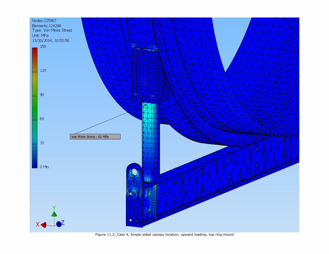
Figure 11.2, Case 4, Single-sided canopy location, upward loading, top ring mount

Benefits
To be of real interest to any potential client there must be visible and tangible benefits for
installing PetroFast modular forecourt system over the conventional systems. It is our belief that
as yet untried layouts there are major advantages and on layouts already installed in the field, we
have firm figures showing substantial savings in cost and installation periods.
Just to summarise some of the advantages.
• Maximum amount of shop fabrication and fit out – guarantying integrity of completed
system.
• Reduction in site installation time, in many cases by over 50%.
• Less complex site work means less specialists required on site.
• Cost will be saved over conventional system – in many cases substantially.
• Reduced customer migration.
• Smaller excavation needed.
• Maximise on site Health & Safety.
This document and the intellectual property contained herein remains the exclusive property of
PetroTechnik International.
PetroTechnik International