Embed Size (px)
Citation preview

LOW VOLTAGE EARTHING POLICY AND
APPLICATION GUIDE EART-01-002
Issue No 4.
1. SCOPE
This document provides guidance on the approach to be adopted when planning, designing and delivering all LV network solutions including, new networks, fault repairs, modernisation, reinforcement and mixed earthing arrangements.
2. ISSUE RECORD
This is a Controlled document. The current version of is held on the EN Document Library. It is your responsibility to ensure you work to the current version. Issue Date Issue No. Author Amendment Details March 2002 1 Alastair Graham November 2007 2 Colin Brown Issue 1 generally revised. EART-
01-004 superseded March 2009 3 Colin Brown Issue 2 updated with comments
from Legal section & general comments
September 2015 4 Gordon MacKenzie Issue 3 general revision. Document restructured to support policy application.
3. ISSUE AUTHORITY
Author Owner Issue Authority Name: Gordon MacKenzie Title: Senior Engineer Engineering Design and Standards
Name: Frank Berry Title: Circuits Manager Engineering Design and Standards
Name: Martin Hill Title: Head of Engineering Design and Standards ................................................. Date: .......................................
4. REVIEW
This is a Controlled document and shall be reviewed as dictated by business or legislative change but at a period of no greater than 3 years from the last issue date.
DISTRIBUTION
This document is not part of a Manual maintained by Document Control and does not have a maintained distribution list.
© SP Power Systems Limited Page 1 of 38
LOW VOLTAGE EARTHING POLICY AND
APPLICATION GUIDE EART-01-002
Issue No 4. 5. CONTENTS
1. SCOPE ....................................................................................................................................... 1 2. ISSUE RECORD ........................................................................................................................ 1
3. ISSUE AUTHORITY .................................................................................................................. 1
4. REVIEW ..................................................................................................................................... 1
DISTRIBUTION ................................................................................................................................ 1
5. CONTENTS ............................................................................................................................... 2
6. REFERENCE AND RELATED DOCUMENTS .......................................................................... 4 7. INTRODUCTION ........................................................................................................................ 4
8. REGULATIONS AND GUIDANCE DOCUMENTS ................................................................... 5
8.1 ESQCR ................................................................................................................................ 5
8.2 Engineering Recommendation G12/4 .............................................................................. 5
8.3 BS761 – Requirements for Electrical Installations ........................................................ 6
8.4 Types of Network and Service Connection .................................................................... 6 9. NEUTRAL AND EARTH CONNECTIONS .............................................................................. 12
10. EARTHING FOR NEW LV NETWORKS ................................................................................. 13
10.1 Underground Mains Distribution ........................................................................... 15
10.2 Overhead Mains Distribution ................................................................................. 15
10.3 Services .................................................................................................................... 16 10.4 Combination or Segregation of HV & LV Earth Electrodes ................................ 16
11. EARTHING FOR EXISTING/MODIFIED LV NETWORKS ..................................................... 18
11.1 Refurbishment/Modernisation ............................................................................... 18
11.2 Network Alterations ................................................................................................ 19
11.3 Repair ....................................................................................................................... 20
11.4 Use of Water pipes as an Earth Terminal ............................................................. 20 12. EARTH LOOP IMPEDANCE ................................................................................................... 21
12.1 Measurement ........................................................................................................... 21
12.2 Recording ................................................................................................................. 21
12.3 Typical Maximum Values ........................................................................................ 21
12.4 High Earth Loop Impedance Resolution ............................................................... 21
13. LOAD BALANCE .................................................................................................................... 23 14. MULTI-OCCUPANCY BUILDINGS ......................................................................................... 23
14.1 Domestic .................................................................................................................. 23
14.2 Commercial/Industrial ............................................................................................ 27
15. PROVISION OF CUSTOMER EARTH TERMINAL ................................................................ 27
15.1 New Connections .................................................................................................... 27
15.2 Cut-out replacement ............................................................................................... 28 15.3 Customer Request .................................................................................................. 28
© SP Power Systems Limited Page 2 of 38

LOW VOLTAGE EARTHING POLICY AND
APPLICATION GUIDE EART-01-002
Issue No 4.
15.4 Repair/Refurbishment ............................................................................................. 28
16. SPECIAL SITUATIONS ........................................................................................................... 29 16.1 LV Supplies associated with Tramways and Railways ....................................... 29
16.2 Construction Sites .................................................................................................. 29
16.3 Temporary Supplies (not associated with construction sites) .......................... 30
16.4 Agricultural & Horticultural Premises ................................................................... 31
16.5 Swimming Pools,..................................................................................................... 31
16.6 Caravans Boats & Marinas ..................................................................................... 32 16.7 Mobile Homes .......................................................................................................... 32
16.8 Mines & Quarries ..................................................................................................... 32
16.9 Petrol Filling Stations ............................................................................................. 32
16.10 Street Lighting and road signs with electrical load of 500W or less ................. 32
16.11 Street Electrical fixtures not covered by section 16.10....................................... 34
16.12 Substation Auxiliary Supplies ............................................................................... 35
© SP Power Systems Limited Page 3 of 38

LOW VOLTAGE EARTHING POLICY AND
APPLICATION GUIDE EART-01-002
Issue No 4.
6. REFERENCE AND RELATED DOCUMENTS
Electricity Safety Quality & Continuity Regulations 2002 (as amended) Electricity Supply Regulations 1988 Energy Networks Association Engineering Recommendation G12/4 Energy Networks Association Engineering Recommendation G87 Energy Networks Association Engineering Recommendation P23 Energy Networks Association Engineering Recommendation G39 BS 7909 Code of Practice for: Design and installation of temporary distribution systems delivering ac electrical supplies for lighting, technical services and other entertainment related purposes. BS 7375 Distribution of Electricity on Construction and Demolition sites. Code of Practice BS 7430 2011 BS 7430 1998 Code of Practice for Earthing BS EN 50122-1 Railway installations BS 7671 2008 Requirements for Electrical Installations IET Wiring Regulations Seventeenth Edition BS 7671 2001 Requirements for Electrical Installations – IET Wiring Regulations Sixteenth Edition Regulations for the Electrical Equipment of Buildings Fourteenth Edition (incorporating amendments 1970 and 1974) HSE Guidance Mines & Quarries HSE Guidance Petrol Stations
7. INTRODUCTION
This policy describes the requirements for the earthing of Low Voltage Distribution Networks in the SP Energy Networks Licence areas. The earthing arrangements on LV networks should be checked to see whether it is to the standard described in this document whenever any of the following situations occur when:
i) Connecting a new substation or recovering an existing substation. ii) Changing a transformer in an existing substation. iii) Reinforcing or extending the network. iv) Repairing the network. v) Customers' earthing facilities which are provided via metallic water pipes are about to be
rendered ineffective by the insertion of non-metallic pipes in distributors or service pipes by the Water Company or plumbing contractors.
vi) The theft of earth-wires or conductors has rendered earthing ineffective. Non-standard or incorrect legacy earthing application should be rectified as per the requirements of this document.
© SP Power Systems Limited Page 4 of 38

LOW VOLTAGE EARTHING POLICY AND
APPLICATION GUIDE EART-01-002
Issue No 4. 8. REGULATIONS AND GUIDANCE DOCUMENTS
The configuration and design of LV networks has changed over the years as have the requirements for the earthing on the network and in customers’ installations. New LV networks shall be designed using Protective Multiple Earthing (PME), whereas extensions and additions to existing LV networks must take account of the existing network conditions and the customer connections. The overriding consideration when planning or carrying out alterations must be the safety of customers and compliance with the requirements of the Electricity Safety Quality and Continuity Regulations (ESQCR). Replacement of service connections on a ‘like for like’ basis without achieving compliance with the requirements of the ESQCR is not acceptable. The key aspects of the ESQCR relating to LV earthing are described below.
8.1 ESQCR
Regulation 8(3)(b) and (c) require that: • Every supply neutral conductor is connected with earth at, or as near as is reasonably
practicable to, the source of voltage except that where there is only one point in a network at which consumer’s installations are connected to a single source of voltage, that connection may be made at that point, or at another point nearer to the source of voltage; and
• No impedance is inserted in any connection with earth of a low voltage network other than that required for the operation of switching devices or of instruments or equipment for control, telemetry or metering.
The application of Protective Multiple Earthing is governed by Regulation 9 which identifies the requirements in regulation 9(2)(a) and (b) which require that: ‘In addition to the neutral with earth connection required under Regulation 8(3)(b) a distributor shall ensure that the supply neutral conductor is connected with earth at:
• a point no closer to the distributor’s source of voltage (as measured along the distributing main) than the junction between the distributing main and the service line which is most remote from the source: and
• such other points as may be necessary to prevent, so far as is reasonably practicable, the risk of danger arising from the supply neutral conductor becoming open circuit.’
In addition Regulation 9(4) requires: The distributor shall not connect his combined neutral and protective conductor to any metalwork in a caravan or boat. It is a requirement of the Electricity Safety Quality and Continuity Regulations, regulation 24 (4) & (5) that
• Unless he can reasonably conclude that it is inappropriate for reasons of safety a distributor shall, when providing a new connection at low voltage, make available his supply neutral conductor or, if appropriate, the protective conductor of his network for connection to the protective conductor of the consumer’s installation.
• In this regulation the expression ‘new connection’ means the first electric line, or the replacement of an existing electric line, to one or more consumer’s installations.
In terms of the Electricity Safety Quality & Continuity Regulations an ‘electric line’ is defined as,
• any line which is used or intended to be used for carrying electricity for any purpose and includes, unless the context otherwise requires-
o any equipment connected to any such line for the purpose of carrying electricity; and o any wire, cable, tube, pipe, insulator or other similar thing (including its casing or
coating) which supports, or is associated with any such line.
8.2 Engineering Recommendation G12/4
The guidance notes issued at the time the ESQC Regulations came into force, state that compliance with the requirements of Regulation 9, covering the application of PME to LV networks where the neutral and protective functions are combined, can be demonstrated by adopting the requirements of Engineering Recommendation G12/3 subsequently amended to G12/4. This Engineering
© SP Power Systems Limited Page 5 of 38

LOW VOLTAGE EARTHING POLICY AND
APPLICATION GUIDE EART-01-002
Issue No 4. Recommendation provides guidance on the application of Protective Multiple Earthing to an LV network and as such will be referenced extensively within this policy document.
8.3 BS761 – Requirements for Electrical Installations
BS7671 Requirements for Electrical Installations otherwise known as the Wiring Regulations sets out the requirements which should be met by a customer’s LV electrical installation in order to ensure safety. Within these requirements are those for the equipotential bonding required between the installation’s earthing conductor and extraneous conductive parts within a customer’s premises. The use of a new earth terminal by any customer connected to the SPEN LV distribution network is contingent upon their compliance with the equipotential bonding requirements of the wiring regulations at the time their installation is connected to the terminal. Table 1 – Requirements for equipotential bonding conductors in customer installations (table 54G BS7671 2008) Copper Equivalent cross-sectional area of the
supply neutral conductor Minimum copper equivalent cross-sectional
area of the main protective bonding conductor
35mm2 or less 10mm2 Over 35mm2 up to 50mm2 16mm2
Over 50mm2 up to 95mm2 25mm
Over 95mm2 up to 150mm2 35mm2
Over 150mm 50mm2
Equipotential bonding is required between the earth conductor and the following extraneous conductive parts:
• Water installation pipes • Gas installation pipes • Other installations pipework and ducting • Central heating and air condition systems • Exposed metallic structural parts of the building
Connection of the main equipotential bonding to a lightning protection system shall be made in accordance with BS EN 62305.
8.4 Types of Network and Service Connection
There are typically four basic kinds of LV service connection which can be found on the SPEN LV networks.
8.4.1 TN-C-S
TN-C-S connections are associated with networks comprising combined neutral earth cables where the neutral and earth functions are combined in a single conductor. This type of cable is used in the construction of all new Protective Multiple Earthing (PME) networks and such a supply is often referred to as a PME supply. PME is not necessarily defined by the type of cable used or limited to a specific type of cable rather by the fact that the neutral conductor, which may or may not also be the only earth conductor in the cable, is connected to earth at multiple points within the network. A feeder constructed using a Combined Neutral Earth cable must comply with the requirements of PME regulations in the ESQCR as described above, whereas a feeder comprising separate neutral and earth conductors need not comply with the requirements to earth the neutral at more than one location beyond the voltage source.
© SP Power Systems Limited Page 6 of 38
LOW VOLTAGE EARTHING POLICY AND
APPLICATION GUIDE EART-01-002
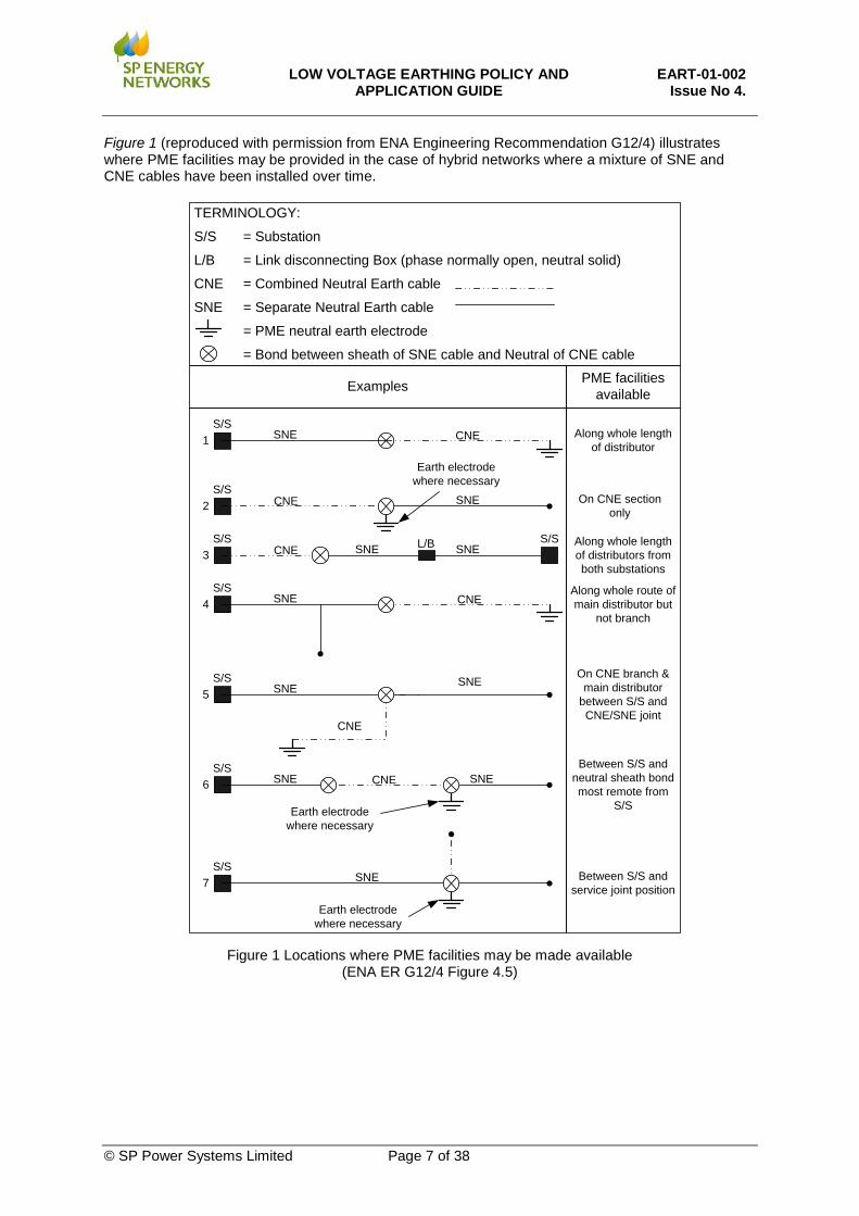
Issue No 4. Figure 1 (reproduced with permission from ENA Engineering Recommendation G12/4) illustrates where PME facilities may be provided in the case of hybrid networks where a mixture of SNE and CNE cables have been installed over time.
Figure 1 Locations where PME facilities may be made available
(ENA ER G12/4 Figure 4.5)
TERMINOLOGY:
S/S = Substation
L/B = Link disconnecting Box (phase normally open, neutral solid)
CNE = Combined Neutral Earth cable
SNE = Separate Neutral Earth cable
= PME neutral earth electrode
= Bond between sheath of SNE cable and Neutral of CNE cable
Examples PME facilities available
1
L/B
7
6
5
4
3
2
S/S
S/S
S/S
S/S
S/S
S/S
S/S
S/S
CNE
CNE
CNE
CNE
CNE
CNE
SNE
SNE
SNESNE
SNE
SNE
SNE SNE
SNE
Along whole length of distributor
On CNE section only
Along whole length of distributors from both substations
Along whole route of main distributor but
not branch
On CNE branch & main distributor
between S/S and CNE/SNE joint
Between S/S and neutral sheath bond most remote from
S/S
Between S/S and service joint position
Earth electrode where necessary
Earth electrode where necessary
Earth electrode where necessary
SNE
© SP Power Systems Limited Page 7 of 38

LOW VOLTAGE EARTHING POLICY AND
APPLICATION GUIDE EART-01-002
Issue No 4.
Figure 2 TN-C-S supply arrangements.
8.4.2 TNS
A TNS supply has a separate neutral and earth conductors between the service point and the neutral earth connection at the source of the main distributor cable.
© SP Power Systems Limited Page 8 of 38

LOW VOLTAGE EARTHING POLICY AND
APPLICATION GUIDE EART-01-002
Issue No 4.
Figure 3 TNS Supply Arrangement
© SP Power Systems Limited Page 9 of 38

LOW VOLTAGE EARTHING POLICY AND
APPLICATION GUIDE EART-01-002
Issue No 4. 8.4.3 TT
In a TT supply the customer’s earth terminal is electrically separate from the SPEN network. In LV networks where only the phase and neutral conductor is distributed and the neutral is not multiple earthed it is essential that the customer provide their own earth terminal to which the protective conductors of their installation must be connected and that this remains separate from the SPEN network.
Figure 4 TT Supply arrangements
© SP Power Systems Limited Page 10 of 38
LOW VOLTAGE EARTHING POLICY AND
APPLICATION GUIDE EART-01-002
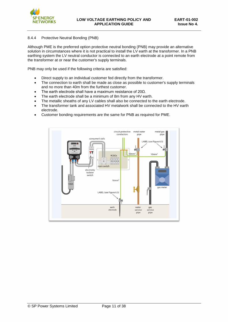
Issue No 4. 8.4.4 Protective Neutral Bonding (PNB)
Although PME is the preferred option protective neutral bonding (PNB) may provide an alternative solution in circumstances where it is not practical to install the LV earth at the transformer. In a PNB earthing system the LV neutral conductor is connected to an earth electrode at a point remote from the transformer at or near the customer's supply terminals. PNB may only be used if the following criteria are satisfied:
• Direct supply to an individual customer fed directly from the transformer. • The connection to earth shall be made as close as possible to customer's supply terminals
and no more than 40m from the furthest customer. • The earth electrode shall have a maximum resistance of 20Ω. • The earth electrode shall be a minimum of 8m from any HV earth. • The metallic sheaths of any LV cables shall also be connected to the earth electrode. • The transformer tank and associated HV metalwork shall be connected to the HV earth
electrode. • Customer bonding requirements are the same for PNB as required for PME.
© SP Power Systems Limited Page 11 of 38

LOW VOLTAGE EARTHING POLICY AND
APPLICATION GUIDE EART-01-002
Issue No 4.
Figure 5 PNB Supply arrangements
9. NEUTRAL AND EARTH CONNECTIONS
Bonding connections to neutral conductors, transformers, switchgear tanks, steelwork, link boxes, pillars and earth electrodes shall be of copper unless otherwise approved. The connection should be related in size to the largest phase conductor, either HV or LV at the substation, substation pole, joint or termination as indicated below, but in any case it must be suitable to withstand the short circuit conditions without damage. The minimum size should not be less than 16mm2 (except for street lighting cable).
Table 2: Neutral and Earth Connections Phase conductor Min Size of Earth Connection 4mm2 cu equivalent 4mm2 cu (Street Lighting only) 35mm2 cu, or 50mm2 Al or less 16mm2 cu 70mm2 cu, or 95mm2 Al or less 32mm2 cu Above 70mm2 cu, or 95mm2 Al 70mm2 cu
Earth connections at poles and substations shall be insulated with 0.8mm thick PVC to at least 600mm below ground and 3m above ground level. They shall be mechanically protected at poles and, where appropriate, elsewhere, with a capping of approved insulating material for at least 250mm below ground and 3m above ground level.
© SP Power Systems Limited Page 12 of 38

LOW VOLTAGE EARTHING POLICY AND
APPLICATION GUIDE EART-01-002
Issue No 4.
Table 3: Typical earthing arrangements to achieve a 20 ohm electrode:
Soil Type Typical Soil Resistivity (ohm-metres)
Horizontal electrode length
Horizontal electrode with 3m vertical earth rods and 5m horizontal sections
Loam, garden soil etc 25 or less 5m
Chalk 50 or less 6m
Clay 100 or less 12m
Sand/Gravel/Clay mix 150 or less 20m
Sand/gravel/clay mix 200 or less 28m
Slate/shale/rock mix 500 or less 75m 7 x 3m vertical rod plus 7 x 5m horizontal sections
Key: Key 3m Vertical Rod 5m Horizontal Electrode
10. EARTHING FOR NEW LV NETWORKS
New Low Voltage Networks shall be designed and constructed in accordance with ESDD-01-006, ESDD-02-003, ESDD-04-003 and ESDD-02-012. The earthing of these networks will apply Protective Multiple Earthing to the main distribution network and earth terminals shall be made available to all customers with the exception of those described in section 16 where PME earthing is inappropriate. Connection of the customer’s earth conductors and equipotential bonding conductors to the SPEN earthing terminal shall only be made by a suitably qualified person who is able to certify the work undertaken and the suitability of the installation. New LV distribution networks shall be constructed in compliance with the requirements of ENA Engineering Recommendations G12/4, G87 and G39 except where varied by the requirements of this policy document. As necessary diagrams from these documents have been reproduced in this document with the permission of Energy Networks Association, the ENA document and diagram reference number are included in the figure annotation. Any variations required by this policy will exceed the minimum requirements of the Engineering Recommendation to either improve safety, simplify implementation or to aim to avoid any future inadvertent breach of the requirements. An example is the placement of neutral earth electrodes.
© SP Power Systems Limited Page 13 of 38
LOW VOLTAGE EARTHING POLICY AND
APPLICATION GUIDE EART-01-002
Issue No 4.
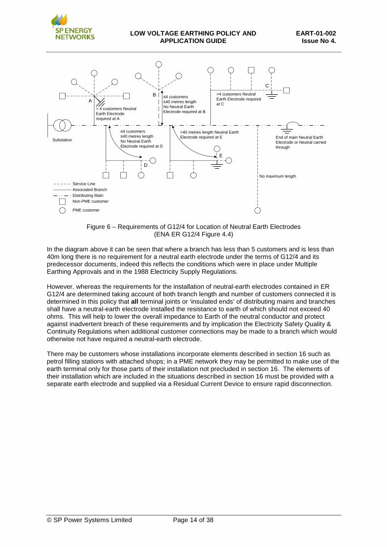
Figure 6 – Requirements of G12/4 for Location of Neutral Earth Electrodes (ENA ER G12/4 Figure 4.4)
In the diagram above it can be seen that where a branch has less than 5 customers and is less than 40m long there is no requirement for a neutral earth electrode under the terms of G12/4 and its predecessor documents, indeed this reflects the conditions which were in place under Multiple Earthing Approvals and in the 1988 Electricity Supply Regulations. However, whereas the requirements for the installation of neutral-earth electrodes contained in ER G12/4 are determined taking account of both branch length and number of customers connected it is determined in this policy that all terminal joints or ‘insulated ends’ of distributing mains and branches shall have a neutral-earth electrode installed the resistance to earth of which should not exceed 40 ohms. This will help to lower the overall impedance to Earth of the neutral conductor and protect against inadvertent breach of these requirements and by implication the Electricity Safety Quality & Continuity Regulations when additional customer connections may be made to a branch which would otherwise not have required a neutral-earth electrode. There may be customers whose installations incorporate elements described in section 16 such as petrol filling stations with attached shops; in a PME network they may be permitted to make use of the earth terminal only for those parts of their installation not precluded in section 16. The elements of their installation which are included in the situations described in section 16 must be provided with a separate earth electrode and supplied via a Residual Current Device to ensure rapid disconnection.
End of main Neutral Earth Electrode or Neutral carried through
AB
C
D
E
Non-PME customer
PME customer
Substation
Distributing MainAssociated BranchService Line
> 4 customers Neutral Earth Electrode required at A
≤4 customers≤40 metres length No Neutral Earth Electrode required at B
>4 customers Neutral Earth Electrode required at C
≤4 customers≤40 metres lengthNo Neutral Earth Electrode required at D
>40 metres length Neutral Earth Electrode required at E
No maximum length
© SP Power Systems Limited Page 14 of 38

LOW VOLTAGE EARTHING POLICY AND
APPLICATION GUIDE EART-01-002
Issue No 4. 10.1 Underground Mains Distribution
• New Underground distribution networks shall be designed and constructed using 3 core waveform cables.
• Neutral Earth Rods shall be installed at the remote ends of all distribution mains and branches.
• The resistance to earth of these earth rods should not exceed 40 ohms. • Where the end of a distributing main is joined to another cable in a link-box or pillar then the
neutral/earth conductors of each circuit shall be permanently connected together • All service breech joints will incorporate a secondary earth connection by means of a
[500mm] solid copper tail installed alongside the cable – testing of this connection is not required
10.2 Overhead Mains Distribution
New LV Overhead distribution shall be designed and constructed using aerial bundled conductor (ABC) suitable to the network design.
• Neutral-Earth Rods shall be installed at the remote ends of all distribution cables. • Additional Neutral-Earth electrodes shall be installed at: • at the end of every Main Line.
• at terminal poles where the ABC is connected to an underground main via fuses. • at sufficient evenly spaced intermediate positions (not more than every 8 spans) to
ensure that the overall resistance to earth of the ABC neutral/earth conductor(s) is below the maximum permitted value.
• at or near to the pole mounted transformer (normally one span away). • The resistance to earth of these earth rods should not exceed 40 ohms • There shall be no new OHL Services to new properties supplied from ABC Main. All new
supplies from new ABC mains shall be via an underground service cable.
Figure 7 Overhead Line Earth Rod Locations
HV Earth Main LV
Neutral Earth
End of Main Neutral Earth
End of Main Neutral Earth
End of Main Neutral Earth
End of Main Neutral Earth
Additional Neutral Earth
© SP Power Systems Limited Page 15 of 38
LOW VOLTAGE EARTHING POLICY AND
APPLICATION GUIDE EART-01-002
Issue No 4. 10.3 Services
Services whether single or three phase shall take account of the nature of the property to which the service is being provided. On a new network services to a single discrete property or to conjoined properties which do not include any internal metallic services or structural metalwork shall be provided using a CNE underground cable. Multi-occupancy buildings are typically flats, apartments, terraced types, where the building may have a single supply from the network with mains & services distributed within the building and those buildings which have multiple service connections to individual premises within the overall building. For all multi-occupied buildings a common service point with the final neutral-earth connection point shall be established for all units within the multi-occupied property. For these types of building the connection from the main to the common service point may be made using a Combined Neutral Earth cable but any distributing main within or outside the building and the services to the individual premises within the overall building shall be made using Separate Neutral Earth cable. For further details see section 14 of this document.
10.4 Combination or Segregation of HV & LV Earth Electrodes
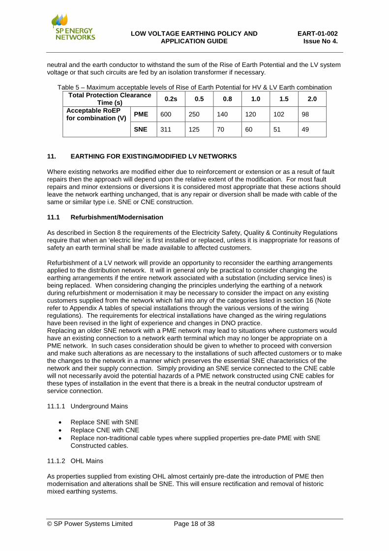
Under the Electricity Supply Regulations it was permitted to combine HV and LV earth electrodes if their combined impedance to earth was less than 1 ohm. In the Electricity Safety Quality & Continuity Regulations this has been changed in Regulation 8(2)(b) to require that ‘the earth electrodes are designed, installed and used in such a manner so as to prevent danger occurring in any low voltage network as a result of any fault in the high voltage network’. Note: Guidance in BS EN 50522 suggests that for PME systems with distributed neutral earth electrodes a factor of 2 may be applied to the tolerable Rise of Earth Potential whereas for SNE systems with a single earth electrode connection the full potential will be exported along the main. The figures in table 5 (page 17) are based on calculation of the touch voltage curves using current curve C2 and a body resistance not exceeded by 95% of the population in line with the requirements of the National Forewords applied to this standard under the terms of the UK’s A-deviation.
10.4.1 Segregation
As a general rule compliance with this regulation will require segregation of the HV and LV electrodes for any secondary substation where there is HV overhead line in the upstream main line or in any alternate HV supply. In such cases any earth fault current would be expected to return to the HV source via the Earth causing a greater Rise of Earth Potential than would be the case for a purely cable fed network where a significant portion of the fault current would be expected to return in the cable sheath. In cases where segregation is required then it is necessary to ensure that at least 8m separation is achieved between the edge of the HV electrode system and the LV Neutral-Earth Electrode. To minimise the transfer potential from the HV earth electrode to the LV earth conductors this first LV electrode should have a resistance to earth of no greater than 20 ohms to ensure that protection systems will operate in the event of an HV – LV inter-winding fault, whilst the combined effect of the more remote electrodes on the LV distribution system must have lower values of earth resistance of 10Ω to 5Ω. If these values cannot be achieved without excessive installation of copper in the ground then further advice should be sought from the Engineering Standards Policy Engineer.
© SP Power Systems Limited Page 16 of 38

LOW VOLTAGE EARTHING POLICY AND
APPLICATION GUIDE EART-01-002
Issue No 4. Where HV and LV earths are segregated at a secondary substation the following values shall apply:
Table 4: Segregation of HV and LV Earths Maximum value Comments
HV Earth 20 ohms The lower the value achieved the better to minimise RoEP for HV faults.
LV Earth at substation 20 ohms
20 ohms is a maximum value to ensure operation of HV protection for a transformer interwinding fault. Very low values are not so desirable as they increase the likelihood of transfer of RoEP caused by HV faults to the LV system
Remote LV system earths Ideally10 ohms
Whilst 10 ohms is target value for the combined effect of all electrodes on the distributed LV system, it is not a maximum value. The lower the value achieved the better to minimise RoEP LV system caused by transfer of RoEP for HV faults. Further analysis will be required where there are high HV fault levels and poor earth
Segregation of HV and LV electrodes is necessary when one or more of the following applies:
• Upstream HV feed or alternate HV feeds contain overhead line between the substation and the source
• The level of anticipated Rise of Earth Potential exceeds the value in table 5 below corresponding to the protection clearance time (this must be assessed taking account of the effect of the HV earth resistance at the substation)
10.4.2 Combination
For entirely urban networks with extensive cable systems the proportion of earth fault current returning via the Earth will be significantly lower with the result that HV and LV electrodes in such cases can generally be combined. The value of Rise of Earth Potential which can be accepted for the combination of HV and LV Earth Electrodes without any further consideration is dependent upon the protection clearance time as the susceptibility of humans to the effects of electric current is a function of both the magnitude of the current and its duration. Combination of the HV and LV earth electrodes is acceptable if the following conditions are met:
• Continuous metallic earth path between the substation and the source substation including alternate feeding arrangements
• The level of anticipated Rise of Earth Potential at the substation is lower than the values contained in table 5 below corresponding to the expected protection clearance time.
For HV supplies to factories and other buildings such as blocks of flats where the intake substation is within the structure it will be necessary to connect the HV and LV earth electrodes together regardless of the form of the upstream HV network in order to avoid any potentially hazardous voltages between HV plant metalwork, building structural metalwork, metallic services and the LV distribution earth conductors which might otherwise be experienced if segregation were to be attempted. In particular for situations where the HV network conditions would otherwise have required segregation it is important that the LV distribution earth is not taken outside the building without considering the possible effects of a Rise of Earth Potential under HV earth fault conditions. The anticipated value of Rise of Earth Potential must be established to ensure that appropriate precautions are taken to either manage the touch potential associated with any earthed metalwork outside the equipotential zone within the building or to segregate the earthing systems inside and outside building and to ensure that the cables and equipment outside the building have sufficient insulation between the phase and
© SP Power Systems Limited Page 17 of 38
LOW VOLTAGE EARTHING POLICY AND
APPLICATION GUIDE EART-01-002
Issue No 4. neutral and the earth conductor to withstand the sum of the Rise of Earth Potential and the LV system voltage or that such circuits are fed by an isolation transformer if necessary.
Table 5 – Maximum acceptable levels of Rise of Earth Potential for HV & LV Earth combination Total Protection Clearance
Time (s) 0.2s 0.5 0.8 1.0 1.5 2.0
Acceptable RoEP for combination (V) PME 600 250 140 120 102 98
SNE 311 125 70 60 51 49
11. EARTHING FOR EXISTING/MODIFIED LV NETWORKS
Where existing networks are modified either due to reinforcement or extension or as a result of fault repairs then the approach will depend upon the relative extent of the modification. For most fault repairs and minor extensions or diversions it is considered most appropriate that these actions should leave the network earthing unchanged, that is any repair or diversion shall be made with cable of the same or similar type i.e. SNE or CNE construction.
11.1 Refurbishment/Modernisation
As described in Section 8 the requirements of the Electricity Safety, Quality & Continuity Regulations require that when an ‘electric line’ is first installed or replaced, unless it is inappropriate for reasons of safety an earth terminal shall be made available to affected customers. Refurbishment of a LV network will provide an opportunity to reconsider the earthing arrangements applied to the distribution network. It will in general only be practical to consider changing the earthing arrangements if the entire network associated with a substation (including service lines) is being replaced. When considering changing the principles underlying the earthing of a network during refurbishment or modernisation it may be necessary to consider the impact on any existing customers supplied from the network which fall into any of the categories listed in section 16 (Note refer to Appendix A tables of special installations through the various versions of the wiring regulations). The requirements for electrical installations have changed as the wiring regulations have been revised in the light of experience and changes in DNO practice. Replacing an older SNE network with a PME network may lead to situations where customers would have an existing connection to a network earth terminal which may no longer be appropriate on a PME network. In such cases consideration should be given to whether to proceed with conversion and make such alterations as are necessary to the installations of such affected customers or to make the changes to the network in a manner which preserves the essential SNE characteristics of the network and their supply connection. Simply providing an SNE service connected to the CNE cable will not necessarily avoid the potential hazards of a PME network constructed using CNE cables for these types of installation in the event that there is a break in the neutral conductor upstream of service connection.
11.1.1 Underground Mains
• Replace SNE with SNE • Replace CNE with CNE • Replace non-traditional cable types where supplied properties pre-date PME with SNE
Constructed cables.
11.1.2 OHL Mains
As properties supplied from existing OHL almost certainly pre-date the introduction of PME then modernisation and alterations shall be SNE. This will ensure rectification and removal of historic mixed earthing systems.
© SP Power Systems Limited Page 18 of 38
LOW VOLTAGE EARTHING POLICY AND
APPLICATION GUIDE EART-01-002
Issue No 4.
• Replace existing open wire 4 wire OHL which has no earth conductor distributed, with SNE (ABC with an incorporated earth wire)
• Replace existing 5 wire OHL with SNE (ABC with an incorporated earth wire) • Consider future customer requests for provision of earth terminal
11.1.3 Services
• Where safe and suitable to do so, an earth terminal consistent with the existing Network construction shall be made available to the customer
• Where Network conditions are suitable, Service modernisation to properties that Pre-date PME shall be SNE constructed
• Where no earth has been previously provided, the System earth type shall be recorded and communicated with the customer.
• It is the customer’s responsibility to connect to the earth terminal provided. • Alterations to the system that impact on non-PME customers may require the SPEN project
manager to install BS7671 Compliant bonding in all affected properties. SPEN policy is to seek to avoid this situation if at all possible.
Customers with an existing SNE supply connected to an SNE cable network can be converted to PME providing the following requirements are satisfied:
• The customer’s installation complies with BS 7671 bonding requirements. This may require the provision of test certification, or visual inspection by qualified staff.
• A new PME cut-out is installed • There are no shared metallic services (water, gas etc.) with other properties (e.g. flats). If
there are shared services then all properties shall be converted to PME and the neutrals bonded together in accordance with the guidance for multi-occupied premises (Section 14).
• Where properties are supplied from ‘looped’ service cables then the earthing arrangements in all properties supplied from the looped services cable shall remain the same (PME or SNE)
• The SNE service cable is replaced with a CNE services cable (or the neutral and earths are combined at both the services joint and the cut-out) NOTE it is NOT permitted to simply combine neutral and earths at the cut-out)
• An earth electrode is installed at the service joint position (unless the mains cable is an interconnector connected to substation earths at both ends)
11.2 Network Alterations
Care should be taken when introducing CNE constructed cables and equipment such as link boxes that non-PME customers are not impacted.
• SNE compatible equipment shall be used wherever possible • Maintain 2 separate return metallic paths • Use of CNE constructed equipment on radial circuits
© SP Power Systems Limited Page 19 of 38

LOW VOLTAGE EARTHING POLICY AND
APPLICATION GUIDE EART-01-002
Issue No 4.
Figure 8- Maintaining SNE with CNE components Due to historic practices, particularly in SP Manweb, of introducing CNE cables into interconnected SNE networks, particular care is required when previously interconnected networks are broken up into radial circuits. Cable records shall be checked for the presence of short sections of CNE cable and one of the following options implemented:
i) Maintain continuity of the neutral in the cases of a CNE cable and the neutral and sheath in the case of an SNE cable
ii) Where through continuity cannot be maintained on a CNE cable the neutral shall be earthed at the termination with a <20ohm electrode.
iii) Where the through connection cannot be maintained on an SNE cable comprising sections of CNE cable the neutral and earth conductors shall be connected together and earthed at the termination with a <20ohm electrode. The installations of all customers beyond the start of the section of CNE cable closest to the source substation shall be inspected and where if necessary have BS7671 compliant bonding installed.
11.3 Repair
When a LV fault is being repaired in order to avoid any potential issues which may occur if the earthing arrangements of the network are altered the repair should replace like for like.
11.3.1 Underground Distribution
With underground cables it may be that the original type of cable is no longer stocked or manufactured, for SNE cables repairs should be undertaken using 4core waveform cable with a copper equivalent cross-sectional area equal to or greater than the cable into which it is being inserted. CNE cables should be repaired with CNE cable.
11.3.2 Overhead Distribution
Overhead LV distribution will be repaired like for like.
11.4 Use of Water pipes as an Earth Terminal
The use of the supply water pipe as an earth terminal ceased to be permitted in the 14th Edition of the wiring regulations in 1966. There may however be properties where this practice continues, where such conditions are discovered a letter to the customer as outlined in Appendix B shall be issued requiring them to take remedial action to ensure that their installation has suitable earthing. Where network conditions permit SPEN will provide an earth terminal compatible with network construction. There may be occasions when the water company are renewing their own mains distribution replacing existing metallic mains pipes with plastic pipes, in such cases any customers still making use of their water pipe as the main earth terminal will have their earthing arrangements rendered ineffective, in such cases a joint letter should be issued from SP Energy Networks and the local Water Company to explain the changes which are being made to the water distribution system and the impacts. A sample of such a letter is contained in Appendix C
Link Box
SNE Cable
SNE Cable
CNE Cable
© SP Power Systems Limited Page 20 of 38

LOW VOLTAGE EARTHING POLICY AND
APPLICATION GUIDE EART-01-002
Issue No 4. 12. EARTH LOOP IMPEDANCE
The value of the Earth loop impedance determines the ability of fuses and miniature circuit breakers to effectively protect a customer’s installation and should be accounted for in the design of those installations. However over time this value may increase due to developing problems on the LV distribution network. On an SNE network high values of Earth Loop Impedance only affect ability of fuses and MCBs to operate correctly, whilst the supply impedance may be unaffected allowing customer’s appliances to function satisfactorily. For a PME network the Earth Loop Impedance and the Supply Impedance are the same and increased values of impedance may affect the satisfactory operation of customer’s appliances which may create other effects such as apparent flicker in their installation.
12.1 Measurement
Earth loop impedance measurements must be made at the cut-out with the earth connections of the property temporarily disconnected from the SPEN earth terminal and the customer’s installation de-energised. All measurements shall be carried out in accordance with the requirements of OPSAF-12-061.
12.2 Recording
For all new connections and whenever an earth terminal is provided for the first time to a customer the Earth Loop Impedance shall be measured and recorded against the associated Meter Point Administration Number (MPAN) in the GIS database.
12.3 Typical Maximum Values
The typical maximum values of Earth loop impedance may be expected to be as per table 6 below
Table 6 – Typical Maximum Earth Loop Impedance Values (Based on ENA ER P23)
Service Capacity up to PME SNE Single Phase 100A 0.35 0.8 Three Phase 100A 0.35 0.8 Three Phase 200A 0.35 0.35 Three Phase 300A 0.2 0.2 Three Phase 400A 0.15 0.15 Three Phase 600A 0.1 0.15
Note: Although these values are the typical maximum values on many LV network it is still possible for an installation to comply with the requirements of BS7671 with higher values and SPEN is under no obligation to provide lower values
12.4 High Earth Loop Impedance Resolution
High Earth Loop impedance measurements at a SPEN earth terminal may be indicative of developing problems on the distribution network. Even in cases where the customer’s installation is adequately protected by a Residual Current Device(s) the presence of high readings requires further investigation and resolution as it suggests a problem with the effectiveness of one or more connections of the earth conductor most likely at cable joint locations. In all cases when a marginally high value of earth loop impedance is measured it is worth considering what value could be expected at that point in the network taking account of the cable sizes and lengths and comparing that against the measured value before embarking on extensive investigation works.
© SP Power Systems Limited Page 21 of 38
LOW VOLTAGE EARTHING POLICY AND
APPLICATION GUIDE EART-01-002
Issue No 4. Where a high Earth Loop Impedance reading is obtained at a SNE service head: • It is not permissible to simply seek to resolve the issue by making a neutral-earth connection at
that point. Further investigation shall be undertaken to establish the whether this is an isolated issue or whether more customers are affected and where on the feeder the problem is being caused.
• Where a customer’s installation is entirely protected by Residual Current Device then for values of
earth loop impedance as measured at the SPEN earth terminal of up to 200Ω it is permissible to consider this as a low priority fault. Where the customer’s installation is not currently protected by a Residual Current Device and the Earth Loop Impedance as measured at the SPEN earth terminal exceeds 2 ohms then there is a risk that the fuses or Miniature Circuit Breakers in the consumer unit will fail to operate within an acceptable time. In such cases it is necessary to either resolve the issue immediately if possible or if that is not possible install a Residual Current Circuit Breaker on the Meter Board between the cut-out and the Meter as a temporary solution until such time as the issue can be resolved in accordance with the low priority fault procedure.
• For higher capacity services the value of earth loop impedance at which the customer’s internal
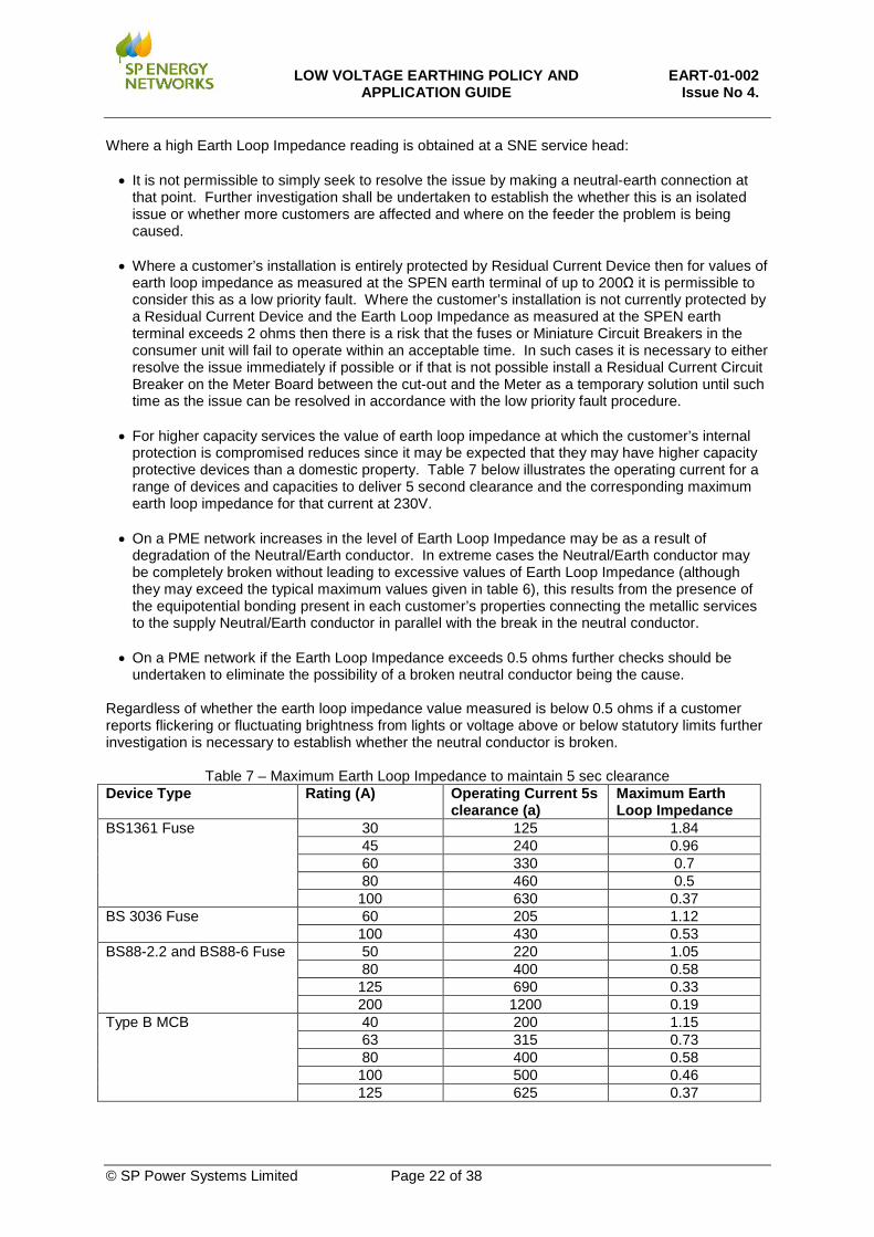
protection is compromised reduces since it may be expected that they may have higher capacity protective devices than a domestic property. Table 7 below illustrates the operating current for a range of devices and capacities to deliver 5 second clearance and the corresponding maximum earth loop impedance for that current at 230V.
• On a PME network increases in the level of Earth Loop Impedance may be as a result of
degradation of the Neutral/Earth conductor. In extreme cases the Neutral/Earth conductor may be completely broken without leading to excessive values of Earth Loop Impedance (although they may exceed the typical maximum values given in table 6), this results from the presence of the equipotential bonding present in each customer’s properties connecting the metallic services to the supply Neutral/Earth conductor in parallel with the break in the neutral conductor.
• On a PME network if the Earth Loop Impedance exceeds 0.5 ohms further checks should be
undertaken to eliminate the possibility of a broken neutral conductor being the cause.
Regardless of whether the earth loop impedance value measured is below 0.5 ohms if a customer reports flickering or fluctuating brightness from lights or voltage above or below statutory limits further investigation is necessary to establish whether the neutral conductor is broken.
Table 7 – Maximum Earth Loop Impedance to maintain 5 sec clearance Device Type Rating (A) Operating Current 5s
clearance (a) Maximum Earth Loop Impedance
BS1361 Fuse 30 125 1.84 45 240 0.96 60 330 0.7 80 460 0.5 100 630 0.37
BS 3036 Fuse 60 205 1.12 100 430 0.53
BS88-2.2 and BS88-6 Fuse 50 220 1.05 80 400 0.58 125 690 0.33 200 1200 0.19
Type B MCB 40 200 1.15 63 315 0.73 80 400 0.58 100 500 0.46 125 625 0.37
© SP Power Systems Limited Page 22 of 38
LOW VOLTAGE EARTHING POLICY AND
APPLICATION GUIDE EART-01-002
Issue No 4. 13. LOAD BALANCE
The voltage which appears on the supply neutral conductor (and consequently on customers’ exposed metalwork) beyond a broken neutral position is influenced by the load balance on the main. If the load is uniformly distributed across the phases along the main, the neutral voltage rise is theoretically zero beyond a neutral break and will be low in practice. Maintaining good load balance will therefore minimise neutral voltage rise and consequent risk of shock under broken neutral conditions. Good load balance will also minimise neutral voltage rise under normal operating conditions, reduce losses, and maximise the load capacity available from the assets concerned. It is the best way to reduce risks associated with broken neutrals and is an extremely important factor in network operation and design.
14. MULTI-OCCUPANCY BUILDINGS
In terms of this earthing policy document the term Multi-Occupancy Building encompasses • Buildings with a single point of supply and internal distribution such as may be found in blocks of
flats or houses which have been split and converted into flats • Buildings which may have a common structure and internal services such as perhaps terraced
houses or industrial units where individual dwellings or premises may have separate electrical services.
The principal concern which exists with such properties in a PME network is the problems associated with neutral current diversion through either metallic services such as gas or water pipes or the actual structure of the building in the case of steel framed buildings.
14.1 Domestic
14.1.1 Blocks of Flats/High Rise
A PME service may be brought into the communal service point within the building with an earth electrode at the point of entrance. The SPEN earth terminal will be bonded to the structural steel work and to metallic services. All Landlord supplies for stairwell lighting, lifts and the like together with all other distribution within the building to the individual customers shall be SNE construction. Whilst this does not prevent any movement of the neutral in the event of a broken neutral on the supplying main it does avoid the concerns regarding Electromagnetic Fields and Electromagnetic Compatibility which may otherwise arise due to diversion of neutral currents through common services and the structural steelwork if the neutral at the end of the internal distributing main had to be bonded to the structural steelwork as a means of effecting the necessary end of main earth electrode for a PME distributor.
14.1.2 Converted Dwellings
A PME service may be brought into the communal service point within the building with an earth electrode at the point of entrance, the SPEN earth terminal will be bonded to any metallic services. All Landlord supplies for stairwell lighting and the like together with all other distribution within the building to the individual customers shall be SNE construction. Whilst this does not prevent any movement of the neutral in the event of a broken neutral on the supplying main it does avoid the concerns regarding Electromagnetic Fields and Electromagnetic Compatibility which may otherwise arise due to diversion of neutral currents through common services within the building.
14.1.3 Terraced properties
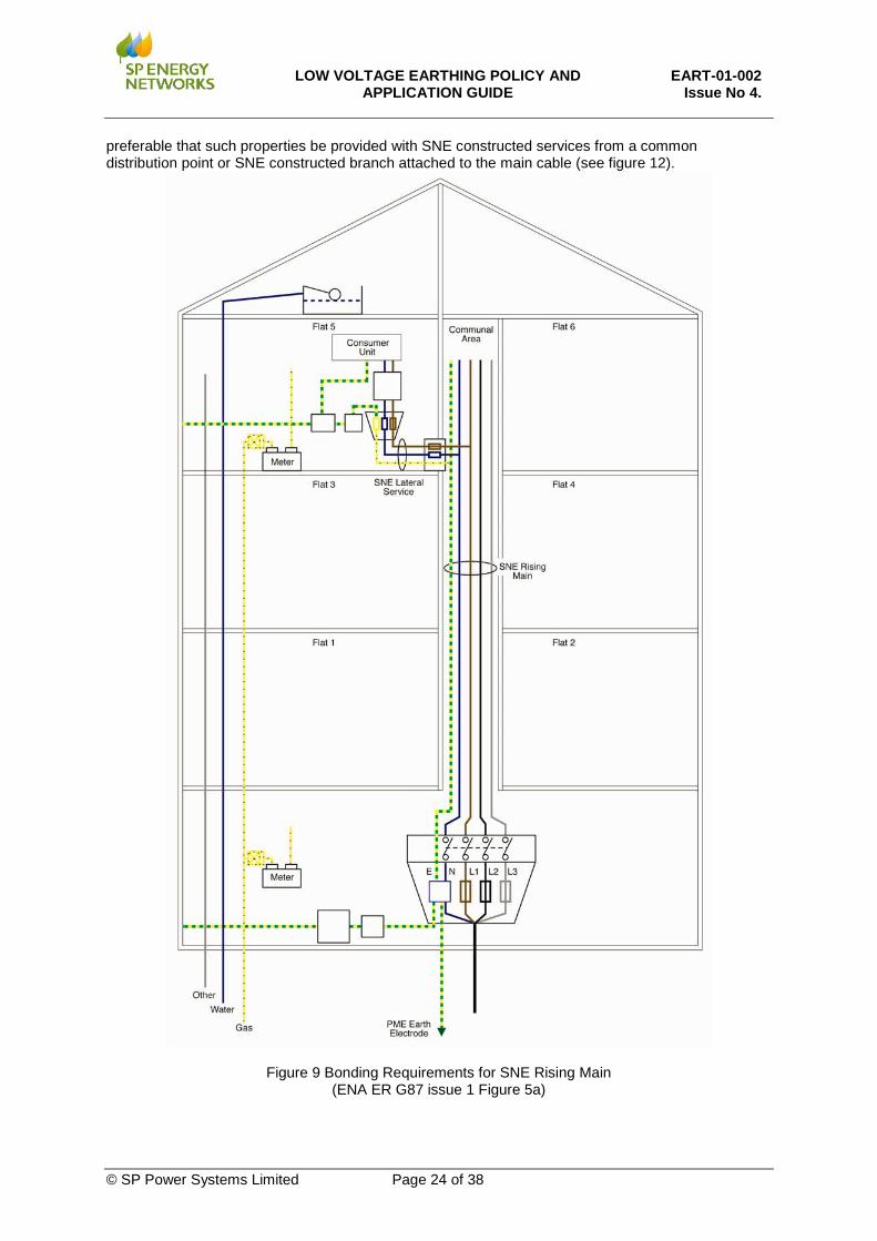
For terraced properties which may have services such as gas and/or water shared within the structure of the building there is an increased potential for neutral current diversion to occur through these services than if the properties were individually serviced from the street. To counter this it is
© SP Power Systems Limited Page 23 of 38
LOW VOLTAGE EARTHING POLICY AND
APPLICATION GUIDE EART-01-002
Issue No 4. preferable that such properties be provided with SNE constructed services from a common distribution point or SNE constructed branch attached to the main cable (see figure 12).
Figure 9 Bonding Requirements for SNE Rising Main (ENA ER G87 issue 1 Figure 5a)
© SP Power Systems Limited Page 24 of 38

LOW VOLTAGE EARTHING POLICY AND
APPLICATION GUIDE EART-01-002
Issue No 4.
Figure 10 Bonding Requirements for SNE Rising Services (ENA ER G87 issue 1 Figure 5b)
© SP Power Systems Limited Page 25 of 38

LOW VOLTAGE EARTHING POLICY AND
APPLICATION GUIDE EART-01-002
Issue No 4.
Figure 11 Bonding Requirements for Group Metering Positions (ENA ER G87 issue 1 Figure 5c)
© SP Power Systems Limited Page 26 of 38

LOW VOLTAGE EARTHING POLICY AND
APPLICATION GUIDE EART-01-002
Issue No 4.
Figure 12 Terraced Houses or Commercial premises with shared internal services
14.2 Commercial/Industrial
14.2.1 Shared Accommodation
Where the building comprises units with shared central accommodation and facilities, such as a reception area, lifts and stairwells a PME supply may be brought into the central service area of the building with a neutral-earth electrode installed at the entrance to the building. The earth terminal will be bonded to the structural steel work of the building and to all metallic services. Landlord supplies and all distribution within the building shall be SNE construction.
14.2.2 Separate Units
Where the building is a common structure with only individual units and no common accommodation or facilities such as a reception area each individual unit will be supplied with Separate Neutral and Earth services from a common distribution pillar or SNE constructed cable which may be supplied from a PME network in which case a neutral earth electrode will be installed at the distribution pillar or the joint at which the SNE cable is jointed to the main distributor. The metallic services for each unit will be bonded to the protective conductor of their respective electricity supply as per figure 12.
15. PROVISION OF CUSTOMER EARTH TERMINAL
Whenever a new earth terminal is provided in line with the requirements below the final Earth Loop Impedance offered to the customer at the completion of the work shall be recorded as described in section 12.
15.1 New Connections
All new customer connections will be offered the use of an earth terminal unless it is inappropriate for reasons of safety when the whole of a customer’s installation falls into one of the categories listed in section 16.
Water
Gas SNE Services
SNE Constructed Branch
CNE Main
Single N-E connection for all properties at the common service point
Note: due to the CNE main all supplies are to a PME standard despite the use of SNE cables
© SP Power Systems Limited Page 27 of 38

LOW VOLTAGE EARTHING POLICY AND
APPLICATION GUIDE EART-01-002
Issue No 4. 15.2 Cut-out replacement
Whenever cut-out replacements are undertaken and the network conditions and the nature of the customer’s installation make it safe and suitable to offer an earth terminal then the opportunity to offer an earth terminal to the customer shall be taken. Where an earth terminal is available prior to the cut-out replacement then an earth terminal shall still be made available after replacement. Where the earth terminal was already in use the customer’s earth conductor shall be reconnected after replacement of the cut-out Although an earth terminal may be made available to the customer for the first time following replacement of a cut-out, there is no requirement to connect the customer’s earth conductors, simply to make it available. Connection of the customer’s installation to the earth terminal shall only be made by a suitably qualified electrician capable of certifying that the requirements for equipotential bonding and where necessary supplementary bonding has been met. Having made an earth terminal available for the first time a letter shall be issued to the customer in line with that described in Appendix D which makes it clear that use of the earth terminal is subject to certification by a suitably qualified person that their installation meets the current requirements of the wiring regulations with regards to equipotential bonding.
15.3 Customer Request
When a customer (or their electrical contractor) makes a request for an earth terminal it is important that this should only be provided if their installation does not fall within the scope of section 16 and that any earth terminal provided is of a type consistent with the LV network to which it is connected. It is not for the customer (or their electrical contractor) to request a PME earth terminal or to demand a particular level of Earth Loop Impedance, the type of earth terminal and the resulting Earth Loop Impedance are both functions of the network to which they are connected, that is not to say that unduly high readings for Earth Loop Impedance are not the responsibility of SPEN to rectify but if a network is an SNE system it will necessarily have higher levels of ELI than would be expected on a similar PME network and this must be recognised. For guidance on acceptable levels of ELI see section 12. Where a customer (or their electrical contractor) makes a request for an earth terminal no charge shall be made in cases where it is determined that modernisation of the supply arrangement is required. Where no other work is being undertaken on the distributor branch or service cable before the request is made it is permissible to charge for the provision of an earth terminal. Where a request is received for the use of a SPEN earth terminal within a multi-occupancy building it is necessary to consider the current earthing status of all of the customers and the nature of the distribution network both inside and outside the building. It is of course preferable that the building network be operated as an SNE distribution. However if the building distribution network is already of a PME construction and other customers are already making use of a SPEN PME earth terminal it is better that a consistent approach be adopted to all customers within the building.
15.4 Repair/Refurbishment
Where the repair or refurbishment of a service is undertaken then under the terms of Regulation 24(4) of the Electricity Safety Quality and Continuity Regulations it is a requirement to make available either the supply neutral conductor or the protective conductor of the network for connection to the protective conductor of the customer’s installation unless it is inappropriate for reasons of safety such as may apply to the conditions outlined in Section 16 of this policy.
© SP Power Systems Limited Page 28 of 38

LOW VOLTAGE EARTHING POLICY AND
APPLICATION GUIDE EART-01-002
Issue No 4. 16. SPECIAL SITUATIONS
The following sub-sections describe the particular issues which affect the suitability of a PME earth terminal for each situation. Further guidance on suitable alternative arrangements may be found in ENA Engineering Recommendation G12/4.
16.1 LV Supplies associated with Tramways and Railways
16.1.1 AC Traction supply points
As a result of the magnitude of traction return current which may be flowing through earth at such sites PME earth terminals are not permitted at traction supply points. LV auxiliary supplies will be provided in accordance with the requirements of ENA Engineering Recommendation P24.
16.1.2 AC tractions systems at locations other than traction supply points
A PME Earth terminal may be provided if the railway operator can demonstrate that their installation will limit the rise of earth potential under both fault and normal traction conditions to the values in ENA Engineering Recommendation G12/4.
16.1.3 LV supplies associated with DC Traction systems
A PME Earth terminal may be provided if the operator can demonstrate that they have or will satisfy the requirements in ENA Engineering Recommendation G12/4 which are designed to minimise the risk of electrolytic corrosion of earthing systems due to stray DC currents and to avoid any external voltage being impressed upon the neutral/earth conductor.
16.2 Construction Sites
The nature of construction sites makes it impractical to maintain compliance with the requirements for equipotential bonding necessary to safely make use of an earth terminal associated with a PME network. Accordingly a PME earth terminal will not be made available for temporary supplies associated with construction activities and equipment. A PME earth terminal may be provided to a suitably constructed site office building from which the earth conductor will not be exported.
16.2.1 Dedicated Transformers – TNS
Sites provided with supplies via a dedicated transformer shall be provided with a Separate Neutral Earth LV supply.
Figure 13 TNS earth from a dedicated transformer (ENA ER G12/4 Figure 6.2.2.1)
HV : LV
DNO secondary substation
L1L2L3NE
Construction site
L1L2L3NE
ConsumerDNO
© SP Power Systems Limited Page 29 of 38

LOW VOLTAGE EARTHING POLICY AND
APPLICATION GUIDE EART-01-002
Issue No 4. 16.2.2 TT Earthing System
If no other earthing system can be provided a TT earthing system shall be employed. The construction site earth conductor is connected to a dedicated earth electrode, installed, owned and controlled by the customer, with a resistance to earth which is at least low enough to meet the requirements of BS 7671 to ensure that the necessary RCD protective device will operate within the required timescales. This earth electrode system must remain separated at all times any PME earth electrode or metallic cable sheath associated with the supply to the overall site
Figure 14 Temporary Building Supply with a TT Earthing system (ENA ER G12/4 Figure 6.2.2.2)
16.3 Temporary Supplies (not associated with construction sites)
In terms of this policy Temporary Supplies applies to direct connections from the SPEN LV distribution network apply to exhibitions, shows and stands mobile or transportable units or structures or temporary buildings (note this does not include Caravans, Boats and Mobile Homes which are addressed in sections 16.6 and 16.7). The provision of supplies to shows and exhibition stands from the electrical installation of a permanent building are covered in Section 711 of BS7671, similarly the provision of supplies to mobile or transportable units from a customer’s installation is governed by Section 717 of BS7671. Examples of mobile or transportable units include Outside Broadcast units, transportable catering units, medical services vehicles etc. BS 7909 provides a code of practice for the design and installation of temporary distribution systems for entertainment related purposes. In the case of ‘permanent’ arrangements for temporary supplies to such equipment such as supply pillars in locations which frequently host such units then it is perhaps prudent not provide an Earth Terminal from a PME network since it will not necessarily be possible to be certain that any connecting units will be continuously under the supervision of a skilled person, that the suitability and effectiveness of that as a means of earthing has been confirmed before connection and that the units are compliant with the normal PME requirements. Temporary buildings such as porta-cabins should take account of the construction of the unit, those with external metalwork which may be connected to the earth terminal and would be capable of being touched by a person outside the structure in contact with the Earth shall not be provided with a PME earth terminal.
HV : LV
DNO secondary substation
Construction site
Other consumer supplies
L1L2L3
N/ E
L1L2L3NE
ConsumerDNO
RCD
© SP Power Systems Limited Page 30 of 38

LOW VOLTAGE EARTHING POLICY AND
APPLICATION GUIDE EART-01-002
Issue No 4. 16.4 Agricultural & Horticultural Premises
Section 705 of BS7671 addresses the requirements for the customer’s installation to safely provide electricity to the outbuildings. The particular issues which give rise to increased concern with supplies to agricultural and horticultural premises are:
• Damp locations
• The greater possibility of a person being in contact with true Earth potential whilst in contact with earthed metalwork
• Livestock and their greater sensitivity to small potential differences between their front and hind legs
As a particular result of the third point where a building which houses livestock does not have a metal grid incorporated in the floor which can be connected to the supplementary equipotential bonding within the location the use of a PME earth terminal is not recommended. Central offices and buildings used for household applications are not covered by Section 705 and may be provided with a PME supply.
16.5 Swimming Pools,
Section 702 of BS761 addresses the requirements for electrical installations associated with swimming pools it is recommended that an earth mat be installed in the floor in Zone 2 surrounding the poolside where a PME supply is provided and the earth terminal is used. The particular issues of concern are the presence of water, the possibility of contact of the body with true Earth potential and the presence of wet barefooted persons who are as a consequence more susceptible to the effects of touch and step potentials if equipotential bonding is not effective. Engineering Recommendation G12/4 provides the following guidance to be offered to electricians enquiring about the use of PME with a swimming pool.
• The main service position can be provided with a PME terminal. It is the electrician’s decision whether or not to utilise the PME terminal for all or part of the installation.
• Where the pool is in separate building or outdoors the consumer’s electrician:
o may decide to use the PME terminal to earth the house / offices/ shop etc. or,
o may decide to segregate (‘gap’) the earth conductor / wire armouring of the pool building circuit, install a separate earth electrode for the pool building and apply equipotential bond as required by BS 7671 Section 702
or, o may decide to use the PME earth if a metallic grid is installed under the poolside
areas and bonded to the equipotential bonding.
• Where the pool is with the same building the consumer’s electrician:
o may decide to use a TT system to earth the entire installation or,
o may decide to use a TT system to earth the pool installation, and segregate the metalwork and pipes from the rest of the building and connect them to a separate earth electrode
or, o may decide to use the PME earth if a metallic grid is installed under the poolside
areas and connected to the equipotential bonding.
© SP Power Systems Limited Page 31 of 38

LOW VOLTAGE EARTHING POLICY AND
APPLICATION GUIDE EART-01-002
Issue No 4. 16.6 Caravans Boats & Marinas
It is expressly forbidden in the Electricity Safety Quality & Continuity Regulations for metalwork in Caravans or Boats to be connected to the combined neutral and protective conductor of a Distributor’s network.
16.7 Mobile Homes
Mobile homes present potential dilemmas, previous versions of the wiring regulations defined these differently to touring caravans and may have permitted the provision of an earth terminal connected to the Distributor’s protective conductor. The 1998 version of BS 7430 specifically mentions such an arrangement in the Note to chapter 21.10 where it describes residential caravans which are not normally intended to be moved from a caravan park as being regarded as permanent buildings which are permitted to use a PME Earth terminal. The seventeenth edition of the Wiring Regulations has a subtly altered definition of caravan from that found in the sixteenth edition. Under the seventeenth edition it is possible to interpret the definition of a mobile home to be the same as for a touring caravan which would preclude their use of a PME Earth terminal. Although a mobile home may not often, if at all, be moved from its location it is still in essence a temporary building and should be considered as such when determining whether an earth terminal can safely be provided, where conductive parts of the structure which would be connected to the earth terminal can be touched by a person outside the structure then a connection to a PME earth terminal shall not be provided.
16.8 Mines & Quarries
The provision of supplies to mines and quarries are governed by the Approved Codes of Practice issued by the Health & Safety Executive. Supplies taken to an underground shaft or to the production side of a quarry must have an earthing system which is segregated from any system bonded to a PME earth terminal. PME facilities may be offered to offices, canteens etc not located in the production side of the mine or quarry.
16.9 Petrol Filling Stations
It is not permitted to utilise a PME earth terminal to provide the earth connection for fuel pumps and equipment located on the forecourt of a filling station. The forecourt area must be supplied by a TT system. It is permitted for the permanent buildings such as restaurants and shops associated with the filling station to be provided with an earth terminal from a PME system provided that the forecourt area has an earth system which is segregated from the PME earth.
16.10 Street Lighting and road signs with electrical load of 500W or less
Individual street lighting columns can be supplied directly from the distribution network and may be provided with a PME earth terminal. Where a series of two or more street lighting fixtures are supplied either using a separate DNO cable or via a lighting authority cable an earth electrode shall be installed both at the pillar which provides the point of supply and at the final lighting column. The metalwork of the column shall not be considered to be an earth electrode.
© SP Power Systems Limited Page 32 of 38

LOW VOLTAGE EARTHING POLICY AND
APPLICATION GUIDE EART-01-002
Issue No 4. ENA ER G12/4 contains the following guidance Part II of the The Electricity Safety, Quality and Continuity Regulations 2002, as amended, which covers protection and earthing, applies to supplies to street lighting installations and other street electrical fixtures. An earth electrode shall be provided at the end of every service supplying more than one street lamp or road sign. In accordance with BS 7671, bonding conductors shall have a minimum size of 6mm2 copper equivalent for supply neutral conductors with copper equivalent cross-sectional areas up to 10mm2. For larger sized supply neutral conductors the main bonding shall comply with Table 4.9a of BS 7671. These requirements apply to street lighting and road signs supplied by a DNO and by a street lighting authority when using CNE cables. In this latter case supply from the DNO is usually to a pillar. See Figure 15 (ENA ER G12/4 6.2.14a.) Private installations and local authority installations using SNE cables which are supplied from PME services must comply with Figure 16 (ENA Er G12/4 6.2.14b). The following principles apply:
a) Bonding of small isolatable metal parts
Small isolatable metal parts, for example small metallic doors and door frames, need not be bonded to earth.
b) Earth electrodes
All earth electrodes installed must comply with paragraph 4.8.
c) Earthing terminal
Until the requirements of BS 7671 and this Engineering Recommendation have been complied with, the earthing terminal should be rendered electrically inaccessible so as to prevent unauthorised connection.
Figure 15 Lighting Authority CNE distributor fed from PME service (ENA ER G12/4 Figure 6.2.14a modified)
© SP Power Systems Limited Page 33 of 38

LOW VOLTAGE EARTHING POLICY AND
APPLICATION GUIDE EART-01-002
Issue No 4.
Figure 16 Lighting Authority SNE Distributor fed from PME service (ENA ER G12/4 Figure 6.2.14b modified)
16.11 Street Electrical fixtures not covered by section 16.10
This Section covers roadside housings accessible to the public; examples are: cable television distribution cabinets, electric vehicle charging points, electrical distribution cabinets with load above 500W. NOTE: A code of practice for electric vehicle charging equipment installation has been published by the IET. Street electrical fixtures should preferably be of Class II construction or equivalent as defined in BS 7671. Examples are public telephones, pedestrian crossing bollards, ticket machines. No mains-derived earthing terminal is required, neither is a residual current device needed for earth fault protection. Where the street electrical fixture is of Class I construction as defined in BS 7671, (examples include metal enclosures containing pumps, controls or communications equipment), a PME earth terminal may be provided if the requirements of BS 7671 are met and:
a) For 3-phase equipment, the load is balanced, or:
b) For 1-phase equipment and 3-phase equipment with unbalanced load, the maximum load and consumer earth electrode resistance bonded to their main earth terminal fulfil the requirements of Table 8 (ENA ER G12/4 table 6.2.15).
If the conditions for a Class I installation cannot be met, a PME terminal should not be offered. The earthing system of the installation should form part of a TT system by installing a separate earth electrode and fitting appropriate protection in accordance with BS 7671 (eg an RCD). Extraneous-conductive-parts (e.g. safety barriers, pedestrian guard rails) should not be connected to a PME earth terminal.
© SP Power Systems Limited Page 34 of 38

LOW VOLTAGE EARTHING POLICY AND
APPLICATION GUIDE EART-01-002
Issue No 4.
Table 8 Maximum customer earth electrode resistance for street electrical fixtures (ENA ER G12/4 table 6.2.15)
NOTE: By agreement with the Network Operator, it may be permissible to take into account the effect of distributed earths in specific situations.
16.12 Substation Auxiliary Supplies
Auxiliary supplies in substations introduce the possibility of inadvertent connection of separated earths or of a voltage gradient (touch potential) between earths where contact can be made simultaneously during fault conditions. At primary substations it is preferable to derive the auxiliary supply from a dedicated pole mounted transformer where the HV and LV earth connections are bonded to the primary substation earth electrode. Where this arrangement is not possible and the LV supply is to be derived from an adjacent LV distribution system which supplies LV customers outside the substation boundary, particular care must be given not to export any rise of earth potential caused by a 33kV or 11kV system fault. Similarly with HV/LV ground mounted substations having separate HV and LV earths, all auxiliary supplies should be isolated from the general low voltage distribution network using a special one to one isolating transformer insulated for 6kV. This will enable all metalwork within the substation to be bonded together and to the substation HV earth.
Connection Maximum 1-ph Load or, for 3-phase, maximum overall load unbalance
Maximum consumer earth electrode resistance bonded to main earth terminal (see note)
1-phase or unbalanced 3-phase
500W 100Ω
1kW 60Ω
2kW 20Ω
3kW 14Ω
4kW 11Ω
5kW 9Ω
© SP Power Systems Limited Page 35 of 38

LOW VOLTAGE EARTHING POLICY AND
APPLICATION GUIDE EART-01-002
Issue No 4. APPENDIX A – Model form letter to customer advising of the unsuitability of water pipes as earth electrodes. Dear Sir/Madam During the course of work associated with the operation and maintenance of the SP Energy Networks Low Voltage network it has come to our attention that your installation is utilising the water supply pipe to your property as an earth electrode. Such an arrangement has not been permitted in the wiring regulations since the publication of the fourteenth edition in 1966. The use of a water pipe as the earth electrode for your electrical installation is strongly discouraged as the electrical integrity of the water pipe and its effectiveness as an earth electrode cannot be guaranteed. It is recommended that you consider either making arrangements for a dedicated earth electrode to be installed outside your property close to the service or alternatively SP Energy Networks can make an earth terminal available from our network. The effective earthing of your electrical installation is the responsibility of the property owner. If you wish to make use of the SP Energy Networks earth terminal it is necessary for the earth conductors and equipotential bonding on your electrical installation to meet the requirements of BS7671, this must be certified by a suitably qualified competent person before any connection is made to the earth terminal. If you have any further questions regarding this matter please contact our connections department on the number below. Tel 0000000000000000 Yours faithfully
© SP Power Systems Limited Page 36 of 38

LOW VOLTAGE EARTHING POLICY AND
APPLICATION GUIDE EART-01-002
Issue No 4. APPENDIX B – Model form letter to be sent to customers when the local water company gives notice that they are replacing metallic mains Dear Sir/Madam We have been advised that the local water company are undertaking replacement works on their mains and/or service pipes. This work will replace existing metallic pipes with new plastic pipes. If the electrical installation in your property is currently reliant on the water pipe to provide the earth connection then these works will render your earth electrode ineffective which has serious implications for the safe operation of your installation. If there is no earth connection to the service cut-out or to the sheath of the service cable or to a separate copper earth rod outside your property then you may be reliant on the water pipe as your earth electrode. If you are not utilising the water pipe as an earth electrode there may still be an earth connection to the water pipe, this is an important additional safety connection and it must not be removed
© SP Power Systems Limited Page 37 of 38

LOW VOLTAGE EARTHING POLICY AND
APPLICATION GUIDE EART-01-002
Issue No 4. APPENDIX C – Model form letters for customers advising regarding requirements for connection to SPEN earthing terminal. Dear Sir/Madam SP Energy Networks have during the course of works on our network made available an earth terminal to which your electrical installation protective conductors may be connected subject to your electrical installation meeting certain minimum standards. The effective earthing of the electrical installation is the responsibility of the property owner. In order to make use of the earth terminal it is essential that your installation meet the requirements of BS7671 with respect to the provision of main equipotential bonding for metallic services such as gas and water pipes and other extraneous conductive parts prior to the connection of the installation earth conductor to this earth terminal. Any connection to the SP Energy Networks earth terminal shall only be made by a suitably qualified competent person who is able to certify that the requirements of BS7671 have been met.
© SP Power Systems Limited Page 38 of 38