Embed Size (px)
Citation preview

Efflorescence and Concrete Masonry Walls ............................ 3
Clear Water Repellent Treatments ............................................. 4
Concrete Masonry Veneer ............................................................ 7
Composite Masonry ....................................................................... 8
Energy Efficiency ........................................................................... 9
Fire Resistive Ratings ...................................................................11
Noise Control .................................................................................12
Wall Weights and Areas ..............................................................13
Technical Articles
©2017 Angelus Block Co., Inc.
The information herein is true and correct to the best of our knowledge but is subject to amendment or correction at any time, without notice. Angelus Block Co., Inc. does not assume responsibility or liability, including liability for negligence, for errors or omissions in this information or in its use in the preparations of architectural or engineering plans or specifications.

This page intentionally left blank.
Tech-3
Efflorescence and Concrete Masonry Walls
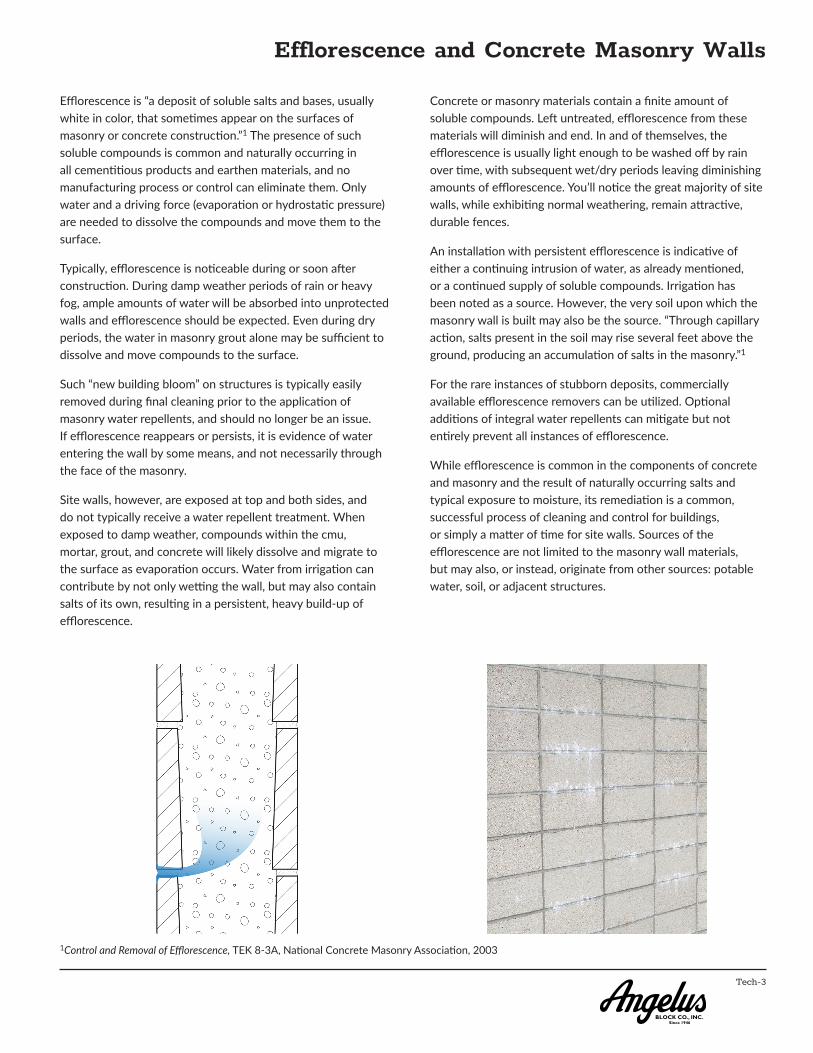
Efflorescence is “a deposit of soluble salts and bases, usually white in color, that sometimes appear on the surfaces of masonry or concrete construction.”1 The presence of such soluble compounds is common and naturally occurring in all cementitious products and earthen materials, and no manufacturing process or control can eliminate them. Only water and a driving force (evaporation or hydrostatic pressure) are needed to dissolve the compounds and move them to the surface.
Typically, efflorescence is noticeable during or soon after construction. During damp weather periods of rain or heavy fog, ample amounts of water will be absorbed into unprotected walls and efflorescence should be expected. Even during dry periods, the water in masonry grout alone may be sufficient to dissolve and move compounds to the surface.
Such “new building bloom” on structures is typically easily removed during final cleaning prior to the application of masonry water repellents, and should no longer be an issue. If efflorescence reappears or persists, it is evidence of water entering the wall by some means, and not necessarily through the face of the masonry.
Site walls, however, are exposed at top and both sides, and do not typically receive a water repellent treatment. When exposed to damp weather, compounds within the cmu, mortar, grout, and concrete will likely dissolve and migrate to the surface as evaporation occurs. Water from irrigation can contribute by not only wetting the wall, but may also contain salts of its own, resulting in a persistent, heavy build-up of efflorescence.
Concrete or masonry materials contain a finite amount of soluble compounds. Left untreated, efflorescence from these materials will diminish and end. In and of themselves, the efflorescence is usually light enough to be washed off by rain over time, with subsequent wet/dry periods leaving diminishing amounts of efflorescence. You’ll notice the great majority of site walls, while exhibiting normal weathering, remain attractive, durable fences.
An installation with persistent efflorescence is indicative of either a continuing intrusion of water, as already mentioned, or a continued supply of soluble compounds. Irrigation has been noted as a source. However, the very soil upon which the masonry wall is built may also be the source. “Through capillary action, salts present in the soil may rise several feet above the ground, producing an accumulation of salts in the masonry.”1
For the rare instances of stubborn deposits, commercially available efflorescence removers can be utilized. Optional additions of integral water repellents can mitigate but not entirely prevent all instances of efflorescence.
While efflorescence is common in the components of concrete and masonry and the result of naturally occurring salts and typical exposure to moisture, its remediation is a common, successful process of cleaning and control for buildings, or simply a matter of time for site walls. Sources of the efflorescence are not limited to the masonry wall materials, but may also, or instead, originate from other sources: potable water, soil, or adjacent structures.
1Control and Removal of Efflorescence, TEK 8-3A, National Concrete Masonry Association, 2003

Tech-4
Clear Water Repellent Treatments(Excerpted from Clear Water Repellent Treatments for Concrete Masonry, published by CMACN and MIA)
Recommendations and Guidelines
In 1992 the Concrete Masonry Association of California and Nevada (CMACN) and the Masonry Institute of America (MIA) held several meetings with masonry contractors, concrete block producers, water repellent treatment manufacturers, applicators, architects, and developers to discuss the proper design and construction methods to make concrete masonry buildings water resistant. Numerous recommendations and guidelines were developed including the following:
1. Pay particular attention to the design phase of the project. Limit horizontal projections, sills, and tops of walls and waterproof those required by the project design with elastomeric coatings. Give special attention to the design of parapets.
2. Cross reference the appropriate specifications sections in Division 4 on masonry construction (typically Section 04 22 00 Concrete Unit Masonry) with those in Division 7 on water repellent treatments (typically Section 07 19 00 Clear Water Repellents).
3. Specify pre-installation meetings to familiarize all parties with the intended methods for prevention of water penetration. The masonry materials, construction, water repellent treatments, and treatment at joints should be discussed along with the expected results and testing procedures.
4. Encourage the use of samples and mockups of masonry construction with the proposed water repellent treatments. Test the mock-ups for water repellency. Mock-up panels should be a minimum 5 ft. by 5 ft. panel and testing should be for at least two hours. Control joints and joint sealants should be included in the mock-up. Tests should be based on the Navy Hose Stream test or a similar field hose stream test.
5. Ensure the use of full shoved head and bed joints (mortar for at least the thickness of the face shell of the masonry unit), if necessary through the use of third party inspections.
6. Specify double struck joints for exterior masonry construction. Require beeholes visible from 5 to 10 feet to be filled by a qualified mason prior to application of the water repellent treatment.
7. Fill cracks that exceed 0.02” in width or 5% of the joint length with mortar by a qualified mason or with joint sealer by a qualified applicator.
8. Apply water repellent treatments in strict accordance with the manufacturer’s installation instructions and
recommendations, by a trained experienced applicator.
9. Field test the concrete masonry walls after the water repellent treatment has cured to assure water repellency.
10. Require a ten year material and labor warranty from the manufacturer and the applicator through the general contractor.
Benefits
Typically, efflorescence is noticeable during or soon after construction. During damp weather periods of rain or heavy fog, ample amounts of water will be absorbed into unprotected walls and efflorescence should be expected. Even during dry periods, the water in masonry grout alone may be sufficient to dissolve and move compounds to the surface.
Selecting concrete masonry as an integral part of the building’s appearance provides numerous benefits for the designer and the owner. Where the gray color of standard cementitious products might provide a cold appearance, use of integral colors gives concrete masonry a warm appearance. The multitude of concrete masonry textures available provides an almost infinite variety of possibilities for building design. And, cost is typically competitive with other types of construction for many buildings.
Applying a clear water repellent treatment to concrete masonry can maintain the appearance of the concrete masonry while providing protection from water intrusion. Additionally, most clear water repellent treatments will keep the concrete masonry looking cleaner longer since a lower permeability prevents dirt from being drawn into the concrete masonry with the water.
Design
Projections and Sills. The cells in concrete masonry construction, and the need to maintain alignment of the cells for reinforcing, limit the tendency of designers to create additional patterns by extending some units beyond the face of the wall. Although this process is possible with concrete masonry, the problems of increased water absorption and penetration through the exposed horizontal surfaces should be considered.
Most clear water repellent treatments are not designed to resist water penetration on horizontal masonry surfaces. Accordingly, ledges formed by projecting units out beyond the face of the wall should be either flashed with sheet metal or patched with an elastomeric coating (see Figure 1).
Sheet metal flashing. Alternately coat sloped mortar with elastomeric paint.
Sloped mortar.
Figure 1: Ledge Detail

Tech-5
Clear Water Repellent Treatments(Excerpted from Clear Water Repellent Treatments for Concrete Masonry, published by CMACN and MIA)
Dense, precast concrete sills, properly sloped and with drip edges, can provide an acceptable sill condition (see Figure 2). Masonry unit sills should also be coated with an elastomeric coating. Avoid mortar sills since they are porous and crack. If used, they should be covered with flashing or coated with an elastomeric coating to prevent water.
Copings, Parapets, and Tops of Walls. Masonry parapets require special attention during design and construction since they will be exposed to weather on both faces as well as on their tops.
Sheet metal caps can effectively resist water penetration through the tops of the parapets if the metal covers the entire top and extends at least two inches down over both faces of the masonry (see Figure 3).
Three inch extensions are preferred to allow for tolerances, and should be considered the minimum extension for split face and scored units. Four inch sheet metal cap extensions are preferred for fluted units to avoid winddriven rain being blown under the cap. Refer to the Sheet Metal and Air Conditioning Contractors’ National Association (SMACNA) literature for proper design of sheet metal, including laps and weathertight installation.
Note that the recommendation is to extend the sheet metal cap two to four inches over the face of the unit, not to have only
two inch to four inch legs on the metal cap. Where wood nailers are used and where the cap flashing is sloped to drain the water from the metal cap, the extension needs to be increased by the dimension of the nailer.
Extensions of the roofing cap sheets over the top of masonry parapets are not recommended. Roofing contractors tend to end the cap sheet several inches from the face of the masonry unit to prevent staining from the bituminous materials. This leaves several inches of the top of the masonry wall exposed. In addition, cap sheets tend to fishmouth due to expansion and contraction, allowing water to enter beneath the cap sheet. Sheet metal caps are therefore preferred.
If mortar caps are placed on top of parapets, they should be amply sloped so water will drain freely. They should also be painted with an elastomeric coating since mortar caps are prone to cracking. Similarly concrete masonry, precast concrete and stone copings should also be painted with an elastomeric coating due to the joints between the units.
Roof Flashing Connections to Concrete Masonry Walls. Counter flashing and base flashing are vital in resisting water penetration between roof structures and concrete masonry walls (see Figure 4). Consideration should be given so the wall strength is not adversely affected by extending the flashing too deeply into the mortar joints.
Control Joints. Proper design of all structures requires recognition of expansion, contraction, and building movement. In concrete masonry structures control joints are used to reduce cracking from these movements. Reinforcing required in seismic areas permit wider spacing of expansion and control joints in concrete masonry.
A control joint is recommended where an interior masonry wall intersects an exterior masonry wall unless the walls are designed to support each other. Control joints are also recommended: at large openings in concrete masonry walls; where there are major changes in concrete masonry wall heights; at changes in wall thickness; where there are control joints in foundations, floors, and roof construction; and in long runs of walls.
Paint with elastomeric coa�ng.
Paint with elastomeric coa�ng.
Concrete masonry sill with sloped face and drip edge
Mortar sill
Reinforced concrete masonry wall
Figure 2: Sill Details
Sheet metal capScrews with washers on interior face of parapet at 2’-0” o.c. Install screws in slo�ed or oversized holes
Waterproof interior face of parapet with appropriate applied materials or flashing
Reinforced concrete masonry wall
Alternate wall cap without a wood nailer
Slope 1 inch per foot by tapering wood nailer or by using sloped coping channels
Connuous cleat
Clear water repellent treatment
Figure 3: Parapet Wall Details
Metal counter flashing. Step down counter flashing as required for roof slope.
Figure 4: Base and Counter Flashing Systems
Reinforced concrete masonry wall
Base flashing. Extend at least 8” above roof.
Roof membrane
Cant strip

Tech-6
Where continuous horizontal steel reinforcing is required to extend through a control joint, sleeves can be placed over the reinforcing to allow the joints to move as designed. Nonstructural reinforcing may be cut at the control joints to allow less restricted movement at the joint (see Section A-A).
1. Additional vertical bars on each side of all control joints.
2. Terminate all non-structural reinforcing 2” from control joints.
3. Provide 4’-0” long smooth dowels across the joint. Prevent bond between bar and grout with grease or a plastic sleeve. Cap all dowels to allow 1” of
movement.
Recommendations vary regarding the appropriate location of joints in long, continuous masonry walls, but DSA has recommended a maximum of 25 ft. o.c. (See DSA IR 21-4.)
Penetrations. Openings throughout concrete masonry walls for scuppers, drains, plumbing, and electrical conduits must be properly flashed and sealed so that the wall can effectively resist moisture penetration. Proper installation of joint sealers around pipes and conduits is especially important since the sealer often serves as not only a moisture barrier but also a flame barrier.
Clear Water Repellent Treatments(Excerpted from Clear Water Repellent Treatments for Concrete Masonry, published by CMACN and MIA)
1
2
See Joint Sealer Detail
Sec�on A-A: Typical Control Joint
12
3
See Joint Sealer Detail
Sec�on A-A: Doweled Control Joint
A A
Wall Eleva�on 1
1/2" Maximum
Ceramic fiber blanketBacker rod
Joint sealer
Sec�on A-A: Control Joint to Achieve a 4-hour Fire Ra�ng
Backer rod
Width of joint
Depth of joint sealer one half the width of the joint
Joint Sealer Detail
B B
Joint sealer
Wall Eleva�on 2 Sec�on B-B: Wall Abutment Joint
Joint sealer
See Joint Sealer Detail
Pipe Penetra�on Detail
Plumbing or electrical conduit
Foam, fiber, or mineral wool fill as required
Clear water repellent treatment to exterior face of wall
Reinforced concrete masonry wallJoint sealer
Scupper Through Fascia with Conductor Head
Gravel stop
Reinforced concrete masonry wall
Tapered edge strip

Tech-7
Concrete Masonry Veneer
Where a full concrete masonry wall is not practical or possible, Veneer units manufactured by Angelus Block afford the same attractive and maintenance-free wall surface as structural cmu. Certain conditions may exist that would dictate use of Veneers instead of a full cmu wall, such as weight limitations in a wall, cantilever, long spans, existing walls, etc. Otherwise, it is generally more economical to construct a conventional structural cmu wall. The installed cost of concrete masonry veneer is very near that of a full hollow unit wall of like face texture, and, added to the cost of the structural backing, will likely total more than the self-supporting cmu wall.
Concrete masonry veneer units are installed as anchored veneer or adhered veneer. Construction and materials are governed by Chapter 14 of the California Building Code and Chapter 12 of MSJC (TMS 402/ACI 530/ASCE 5). See Masonry Veneer Code References. Please refer to the code for specific requirements.
A common veneer system consists of (from inside out) the structural back-up (studs and plywood sheathing shown here), waterproof sheathing, wall �es, 1-inch min. air space, joint reinforcement, and the cmu/mortar installa�on.
The basic elements of a veneer applica on above an opening, including a steel angle lintel and flashing.
For Seismic Design Categories E and F, the �e shall have a lip to engage horizontal joint
Basic Wall Types
Corrugated
Slot

Tech-8
Composite Masonry
Composite, multiwythe grouted masonry is a versatile solution for a variety of construction situations. Variable wall widths from 8 inches to 24 inches, or more, in 1 inch increments, are facilitated by the length of wall tie used. Note that for normal design conditions, standard types of hollow load-bearing cmu are best for wall construction up through 16 inch widths. For wall widths over 16 inches or for certain design considerations, composite masonry should be considered.
The challenge of limited construction clearance, due to zero lot line or existing structures can be mitigated with composite masonry. Where it would be impossible to build and strip conventional forms for poured-in-place concrete, multiwythe units can be laid up from one side of the wall after reinforcement is in place.
Extreme reinforcement requirements are not a hindrance as multiwythe construction provides a continuous grout space. Thus, solid units maneuver through and around in-place reinforcing bars.
Construction consists of solid units, manufactured to the standard appropriate for the code jurisdiction, in two wythes, and tied together by approved wall ties embedded in the mortar joints. The grout space between the wythes contains the reinforcement and is solid grouted. See CBC References.
(CMU for use in composite masonry are sometimes referred to as “components” or “expando” units. Nothing proprietary is required; most units are also used for veneer applications; composite and veneer units are typically interchangeable.)

Tech-9
Energy Efficiency(Excerpted from Take Credit for a Good Design, published by CMACN)
We design buildings with masonry for many reasons . . . to be attractive and comfortable, to be durable, to keep out wind, rain and noise. We can also use masonry for energy efficiency.
Thermal Mass Saves Energy
Thermal mass in masonry walls moderates the day/night temperature swings and reduces heat flow to the interior, which reduces air conditioning loads inside the building.
For thousands of years, designers and builders have understood the valuable qualities of masonry, but many have become confused about its role in building energy performance. Because of an emphasis on high insulation levels, the importance of thermal mass has been overlooked.
We’ve become more sophisticated about energy efficiency, however, and have now quantified and accepted the benefits of thermal mass. The newest energy standards recognize this quality of masonry walls, allowing a reduction in insulation requirements as wall heat capacity increases.
Masonry Walls Offer Thermal Mass
The biggest energy problem in commercial buildings has been to remove unwanted heat. Internal heat gains from lights, equipment and people lead to year-round air conditioning. Outdoor heat gains just add to the problem. But the thermal mass of masonry allows it to absorb much of the heat, reducing the load on the air conditioning system.Construction consists of solid units, manufactured to the standard appropriate for the code jurisdiction, in two wythes, and tied together by approved wall ties embedded in the mortar joints. The grout space between the wythes contains the reinforcement and is solid grouted. See CBC References.
Here’s how it works: For outside heat to impact the cooling system, it must conduct through the wall by warming up the wall material. If the wall has high thermal mass, it takes a great deal of heat and time to warm it up. When the heat finally makes it through the wall, it is less intense. During cooler nights, this process is reversed; the heat flows out of the wall, and cools it down.
In many climates, this cycle of heat flowing into and out of masonry walls results in substantially lower annual air conditioning loads.
Interior Masonry Walls Save Energy, Too
Interior masonry walls work much like their exterior counterparts, but excess heat is absorbed from inside rather than outside. During the day, the walls absorb heat from inside the building - accumulated heat from the sun, lights, equipment and people. At night the heat is released. This helps cool the building during the day and keep it warm at night. Passive solar heating systems rely on interior thermal mass.
In the summer months, interior masonry can be “precooled” by nighttime ventilation of the building to better absorb heat and cool the building during the day.
R-Values Are Just Part of the Story
R-values provide a measure of resistance to heat flow in walls or other building elements. They are useful in gaining initial understanding of heat flow in buildings, and for calculating peak heating loads. They are unable to account for heat capacity. Therefore, R-values are of limited usefulness in understanding long-term cooling or heating loads, or for predicting annual energy costs.

Tech-10
Energy Efficiency
In many respects, the California Energy Code (CEC), and its supplementary manuals and appendices, are more advanced in treatment of material performance than the International Energy Conservation Code (IECC) used in other states. Concrete masonry in particular is well represented in the CEC, and its inherent benefits for energy design are demonstrated in the code’s prescriptive requirements.
The CEC has mandatory provisions, and two optional paths to compliance:
Performance approach, where approved compliance software calculates the energy budgets for both the baseline standard design building and the proposed design building.
Prescriptive approach, where the provisions of CEC Section 140.2 must be met for the project’s climate zone.
The performance approach is by far the most utilized in California as it offers greater flexibility in design, more accurately accounts for systems (including concrete masonry walls), and maximizes potential credits for green rating systems such as LEED®. The prescriptive requirements are very conservative and come into play in establishing the baseline.
The code references below are from mandatory and prescriptive sections of the CEC. Though prescriptive requirements are typically used for a design baseline, they are useful in demonstrating the energy effectiveness of concrete masonry. In particular, the high R-values in mandatory and prescriptive requirements for framed walls do NOT correlate to concrete masonry, which is a heavy mass wall. Unlike framed walls, concrete masonry has no mandatory insulation requirement; the CEC recognizes the substantial benefit in heavy mass walls.
From 2016 California Energy Code:
TABLE 140.3-B – PRESCRIPTIVE ENVELOPE CRITERIA FOR NONRESIDENTIAL BUILDINGS[Excerpts where minimum 8-inch wide solid grouted concrete masonry wall meets requirement with no additional insulation.]
ENVELOPE > Max U-Factor > Walls > Mass Heavy1
CLIMATE ZONE
2 3 4 5 6 7 8 9 10
0.65 0.65 0.65 0.65 0.69 0.69 0.69 0.69 0.65
TABLE 140.3-C – PRESCRIPTIVE ENVELOPE CRITERIA FOR HIGH-RISE BUILDINGS AND GUEST ROOMS OF HOTEL/MOTEL BUILDINGS[Excerpts where minimum 8-inch wide solid grouted concrete
masonry wall meets requirement with no additional insulation.]
ENVELOPE > Max U-Factor > Walls > Mass Heavy1
CLIMATE ZONE
6 7 8 9 10
0.69 0.69 0.69 0.69 0.69
1Heavy mass walls are walls with a heat capacity of at least 15.0 Btu/h-ft2. [See excerpt from appendices below]
Note: As shown above in Tables 140.3-B and C, 8-inch solid grouted concrete masonry meets the prescriptive requirement for U-factor in many Climate Zones (Figure 1). In the other Zones with prescriptive requirements for lower U-factors, only nominal additional insulation is needed to lower the UTotal to required values; typically significantly less than would be required for framed walls. See 2016 Joint Appendices, JA-4.1.4 below.
From 2016 Reference Appendices, 2016 Joint Appendices, Appendix JA-4.1.4:
Table 4.3.5 Properties of Hollow Unit Masonry Walls[Excerpts for Medium Weight, solid grouted. Shaded cells indicate column and row numbers from Table 4.3.5.]
Solid Grout
Thickness Type A
1 U-factor HC
12” MW CMU 3 0.54 23.9
10” MW CMU 6 0.59 19.7
8” MW CMU 9 0.65 15.7
Figure 1 – Southern California Climate Zones with Concrete Masonry Heavy Mass Wall Overlay
An 8-inch wide or greater concrete masonry wall, with Medium Weight cmu, solid grouted, meets the prescriptive requirements for the Southern and Central California coastal areas, including the major metropolitan regions, without any mandatory insulation.
For a more detailed review of the CEC and concrete masonry, please see our 2016 California Energy Code References.

Tech-11
Fire Resistive Ratings
Concrete masonry is a preferred material for use in constructing fire-resistive walls. It is a multi-functional system in a single package:
Noncombustible, stable in response to fire
Structurally sound, exceptional seismic performance
No toxic gases released when heated
Durable, long-lasting, with low life-cycle costs
The fire-resistance ratings of the various thicknesses of concrete masonry walls are based on 2016 CBC Table 721.1(2), Rated Fire-resistance Periods for Various Walls and Partitions, Item Numbers 3-1.1 through 3-1.4:
3-1.1 Expanded slag or pumice
3-1.2 Expanded clay, shale or slate
3-1.3 Limestone, cinders or air-cooled slag
3-1.4 Calcareous or siliceous gravel
Partial Grouted Solid Grouted
CMU ASTM C90 Wt. Classification NW MW LW NW MW LW
Nom
inal
Wid
th
4 <1 Hour <1 Hour 1 Hour 1 Hour 1 Hour 1 Hour
6 1 Hour 1 Hour 1 Hour 3 Hours 3 Hours 3-4 Hours*
8 1 Hour 1 - 2 Hours* 2 Hours 4 Hours 4 Hours 4 Hours
10 2 Hours 2 Hours 2 Hours 4 Hours 4 Hours 4 Hours
12 2 Hours 2 Hours 3 Hours 4 Hours 4 Hours 4 Hours
* May depend on manufacturing location or product specified. Consult your representative for more information.
Equivalent thicknesses are defined in 2016 CBC Section 722.3.1.
For partially grouted concrete masonry walls using 8-inch thick cmu rated at 2 hours, the fire-resistance rating can be increased to 4 hours when ungrouted cores are filled with any of the following:
Silicone-treated perlite loose-fill insulation conforming to ASTM C 549.
Vermiculite loose-fill insulation conforming to ASTM C 516.
Expanded clay, shale, or slate lightweight aggregate conforming to ASTM C 331.
Sand of slag having a maximum particle size of 3/8 inch, and conforming to ASTM C 33.
The calculated equivalent thickness of a concrete masonry wall may include the thickness of applied plaster and lath, gypsum wallboard, or gypsum plaster.
The fire-resistance rating of walls with cmu using blended aggregates is determined per 2016 CBC Section 722.3.1 and ACI 216.1/TMS 0216 [upon which Section 722.3.1 is based].
See our Masonry Fire-Resistance-Rated Construction Code References. The document highlights code sections related to masonry and fire-resistance.

Tech-12
Noise Control(Excerpted from 2012 Design of Reinforced Masonry Structures, published by CMACN)
Sound Insulation
There are two properties of concrete masonry that make it useful as a noise-controlling material. The first characteristic is its effectiveness as a sound barrier that reflects sound waves. The second property is its ability to absorb sound and further minimize the sound that is transmitted through a concrete masonry wall. As shown in Figure 1, both of these characteristics combine to make concrete masonry extremely effective in preventing sound transmission over a wide range of frequencies.
Figure 1 Noise Reduction with Concrete Masonry Walls
Sound absorption is particularly important in auditoriums, concert halls and other locations where noise reflection needs to be minimized to control the sound generated within a room. The sound absorption coefficient defines how effectively a surface absorbs noise. A sound absorption coefficient of 0.25 indicates that 25% of the sound striking the surface is absorbed by the wall at the frequency being considered. The noise reduction coefficient (NRC) is the average of the sound absorption coefficient at frequencies of 250, 500, 1000 and 2000 hertz. Table 2.6.1 provides the approximate values of the NRC for some concrete masonry walls. The table shows that lighter material is more efficient in absorbing sound waves. Application of paint and other finishes to concrete masonry typically reduces the NRC value by increasing the amount of sound reflected by the wall.
TABLE 1: Approximate Noise Reduction Coefficients (NRC) for Unpainted Concrete Masonry Walls
Surface Texture
Coarse Medium Fine
Lightweight Concrete Masonry
0.50 0.45 0.40
Normal Weight Concrete Masonry
0.28 0.27 0.26
The challenge of sound insulation is different from sound absorption and is more critical in multi-family residential buildings when compared to other types of structures. In addition to reducing the noise transmitted into the building interior from exterior sources such as traffic, sirens, etc., there must be sufficient insulation to control the transfer of noise between occupants of adjacent units. Sound control is achieved by minimizing the transmission of sound from one side of a wall to the other by utilizing both the reflective and absorptive characteristics of concrete masonry walls. The ability of concrete masonry to isolate sound in this manner is defined by the sound transmission class (STC). ASTM Standard E90, “Standard Test Method for Laboratory Measurement of Airborne Sound Transmission Loss of Building Partition Elements”1, provides procedures for determining the STC of walls and partitions. The testing involves measuring the decrease in sound energy across a wall for a wide range of frequencies and comparing the results to a standard loss contour.
In lieu of the experimental procedure outlined in ASTM E90, empirical equations have been developed to estimate the STC ratings for various masonry walls. TMS 302, “Standard Method for Determining Sound Transmission Ratings for Masonry Walls”2 provides such relationships. For concrete masonry walls that have a thickness of 3 inches or greater, the STC rating is given by:
STC= 20.5W0.234 (1)
where W is the weight of the wall in psf. Unlike sound absorption, the ability of a wall to block sound improves with density. Table 2 provides the STC values using Equation (1) for some solid grouted walls constructed with normal weight concrete masonry units. STC values for walls constructed with different weight block, or for walls that are partially grouted may be estimated using the appropriate wall weight and Equation (1). Building codes generally require that the STC values between living units be no less than 40 to 50.
TABLE 2: Typical STC Ratings of Solid Grouted Masonry Walls Constructed with Normal Weight Concrete Masonry Units
Nominal Thickness (inches)
Weight(psf)
Calculated STC Rating
6 63 54
8 84 58
10 104 61
12 133 64
Transmi�edSound
INPUTSOUND
ReflectedSound
AbsorbedSound
1 ASTM, “Standard Test Method for Laboratory Measurement of Airborne Sound Transmission Loss of Building Partition Elements,” Standard E90-09, Annual Book of ASTM Standards, Volume 04.06, ASTM International, West Conshohocken, Pennsylvania, 2014.
2TMS Standards Development Committee, “Standard Method for Determining Sound Transmission Ratings for Masonry Walls,” The Masonry Society, Longmont, Colorado, 2012.

Tech-13
Wall Weights and Areas(Excerpted from 2012 Design of Reinforced Masonry Structures, published by CMACN)
Average Weight of Completed Wall1 (psf) and Equivalent Solid Thickness (in)
Hollow Concrete BlockEquivalent Solid Thickness2
InchesLightweight103 pcf
Medium Weight115 pcf
Normal Weight135 pcf
Wall Thickness 6" 8" 10" 12" 6" 8" 10" 12" 6" 8" 10" 12" 6" 8" 10" 12"
Solid Grouted Wall 52 75 93 118 58 78 98 124 63 84 104 133 5.6 7.5 9.6 11.6
Vertical Cores Grouted At
16" o.c. 41 60 69 88 47 63 80 94 52 66 86 103 4.5 5.8 7.2 8.5
24" o.c. 37 55 61 79 43 58 72 85 48 61 78 94 4.1 5.2 6.3 7.5
32" o.c. 36 52 57 74 42 55 68 80 47 58 74 89 4.0 4.9 5.9 7.0
40" o.c. 35 50 55 71 41 53 66 77 46 56 72 86 3.8 4.7 5.7 6.7
48" o.c. 34 49 53 69 40 51 64 75 45 55 70 83 3.7 4.6 5.5 6.5
1 The above table gives the average weights of completed walls of various thickness in pounds per square foot of wall face area. An average amount has been added into these values to include the weight of bond beams and reinforcing steel. Weight of grout is assumed at 140 pcf.
CMU per Square Foot of Wall Area
Unit Length
UnitHeight
16 18 24
4 2.25 2.00 -
6 1.5 1.33 -
8 1.125 1.00 .75
Example:
Wall Area = 12,500 sq. ft.
Unit Face Size = 8 x 16
12,500 x 1.125 = 14,063 Units
2 Equivalent solid thickness means the calculated thickness of the wall if there were not hollow cores, and is obtained by dividing the volume of solid material in the wall by the face area of the wall. This Equivalent Solid Thickness (EST) is for the determination of area for structural design only, e.g. fs = P/(EST)b. It is NOT to be used to obtain fire ratings. Fire rating thickness is based either on equivalent solid thickness of ungrouted units only or solid grouted walls.