Embed Size (px)
Citation preview
Issue 3 Rev B Page 1 of 43 dated 1st January 2013
Certification Services Division Newton Building, St George’s Avenue Northampton, NN2 6JB United Kingdom Tel: +44(0)1604-893-811. Fax: +44(0)1604-893-868. E-mail: [email protected]
PCN/GEN Appendix Z1 iss 3 Rev B – NDT Training Syllabi Contents Page 1 Scope ................................................................................................................................. 2 2 Introduction, Terminology, Purpose and History of NDT ............................................ 2 2.1 The Task of NDT ............................................................................................................... 2 2.2 The Task of NDT personnel ............................................................................................. 2 2.3 The History of NDT ........................................................................................................... 2 2.4 Terminology of NDT ......................................................................................................... 3 2.5 General safety considerations ........................................................................................ 3 A Radiographic testing level 1, level 2 and level 3 ........................................................... 4 B Ultrasonic testing level 1, level 2 .................................................................................. 17 C Eddy current testing level 1, level 2 and level 3 .......................................................... 22 D Penetrant testing level 1, level 2 and level 3 ............................................................... 29 E Magnetic particle testing level 1, level 2 and level 3 .................................................. 33 F Syllabus visual testing level 1, level 2 and level 3 ...................................................... 38
Introduction ISO/TC135 and CEN/TC138 are proud to present to the worldwide Non Destructive Community their recommendations for minimum requirements of technical knowledge of NDT personnel; these recommendations provide means for evaluating and documenting the competence of personnel whose duties require the appropriate theoretical and practical knowledge. As part of the efforts to streamline and harmonize the training and certification of NDT personnel, ISO/TC135 - CEN/TC138 have been actively involved in developing guidelines for training syllabus and guidelines for NDT training organisations. These guides serve to those involved in training and are useful to achieve a uniform level of training material and consequent competence of personnel. These documents represent 2 years of efforts of ISO/TC135 and CEN/TC138 working groups to promote harmonisation and mutual recognition of minimum requirements of the different existing certification schemes. The content of this first edition has been based on the experience of the experts as well as comments of the end-user industries and the last publication of the ICNDT recommended guidelines.

Issue 3 Rev B Page 2 of 43 dated 1st January 2013
The time allotment for the different topics takes into account the latest developments in each method and consequently the total duration can be sometime greater than the minimum duration required by EN ISO 9712. This document will be updated along the years in order to maintain a workable document in line with the incoming NDT methods and techniques. ISO/TC135 and CEN/TC138 wishes to express their appreciation to all those who contributed to the production of this publication. 1 Scope This document defines guidelines with the intention to harmonise and maintain the general standard of training of non-destructive testing (NDT) personnel for industrial needs. Associated guidelines for NDT training organisations have been produced for the general part of training courses. The guidelines also establish the minimum requirements for effective structured training of NDT personnel to ensure eligibility for qualification examinations leading to third party certification according to recognized standards. This document enclose a clause about NDT in general and a clause specific to each of the following NDT method: acoustic emission testing, eddy current testing, leak testing, magnetic particle testing, penetrant testing, radiographic testing, ultrasonic testing and visual testing,. 2 Introduction, Terminology, Purpose and History of NDT 2.1 The Task of NDT Non-destructive testing (NDT) gives an important contribution to the safety and the economic and ecological welfare of our society. NDT is the only choice for the test of an object which must not be destroyed, modified or degraded by the testing process. This is generally required for objects which will be used after testing, for example safety parts, pipelines, power plants and also constructions under in-service inspection, but even for unique parts in archaeology and culture. NDT is based on physical effects at the surface or the inner structure of the object under test. Often the outcome of the test needs to be interpreted to give a useful result; sometimes different NDT methods must be combined, or verified by other test methods. 2.2 The Task of NDT personnel NDT personnel have a high responsibility not only with respect to their employers or contractors but also under the rules of good workmanship. The tester shall be independent and free from economic influences with regard to his test results, otherwise the results are compromised. The tester should be aware of the importance of his signature and the consequences of incorrect test results for safety, health and environment. Under legal aspects, the falsification of certificates is an offence and judged according to the national legal regulations. A tester may find himself in a conflicting situation about his findings with his employer, the responsible authorities or legal requirements. Finally the tester is responsible for all interpretations of test results carrying his signature. NDT personnel should never sign test reports beyond their certification. 2.3 The History of NDT NDT started with visual checks in prehistoric times. In medieval centuries, test methods like simple leakage tests and hardness checks were introduced. The breakthrough for NDT came with industrialisation in the 19th and 20th century: X-ray and Ultrasonic Testing for inner defects, Penetrant and Magnetic Particle Testing for surface cracks. During the last few decades sophisticated, mostly electronically linked methods like Eddy Current Testing, RADAR, Computer Tomography and Thermography were developed. NDT methods found application in a wide range of industry from civil engineering and industrial plants to space and defence technology. The history of NDT is linked to many famous researchers and inventors like Röntgen, Becquerel, Curie, Oerstedt, Faraday and even Leonardo da Vinci. They discovered the physical principles and demonstrated early applications. All together, approximately 5000 scientists worldwide made contributions to the present state of NDT. NDT is a global technology. Since NDT tasks and related technical problems are similar in all developed countries, improved solutions and new equipment are spread around the world within a few months. Many international conferences and standard committees contribute to a steady and consensual development of NDT for the benefit of safety, economy and the environment.

Issue 3 Rev B Page 3 of 43 dated 1st January 2013
2.4 Terminology of NDT Correct Terminology is a necessary demand for a worldwide-applied technology. It is needed for communication between contracting parties, testers and certifying bodies. Terms like “Indication”, “Imperfection”, “flaw” and “defect” need a precise and unequivocal definition to avoid any confusion and misinterpretation of results. The European Standards EN 1330–1 and –2 (for different NDT methods) and the synonymous International Standards (partly drafts) give the agreed denominations and short definitions of terms. 2.5 General safety considerations 2.5.1 Non-destructive testing is often applied in conditions where safety of the operator may be in danger due to local conditions, or where the application of the particular NDT method or techniques may in itself compromise the safety of operator and others in the vicinity. An essential element of any course training for NDT personnel must therefore be safety and the duration of the training for this subject should be adequate and provided addition to the technical training associated with the particular NDT method. 2.5.2 General safety considerations may include but are not necessarily limited to: Environmental conditions: heat, cold, humidity; Toxicity: of NDT materials, tested products, atmosphere; Radiation safety: NDT materials,products, local regulations Electrical safety: NDT equipment, lethal voltages, EMC; Potential of personnel injury: working at height or in other dangerous environments; Personnel protection equipment: closing, radiation dosimeters.
Issue 3 Rev B Page 4 of 43 dated 1st January 2013
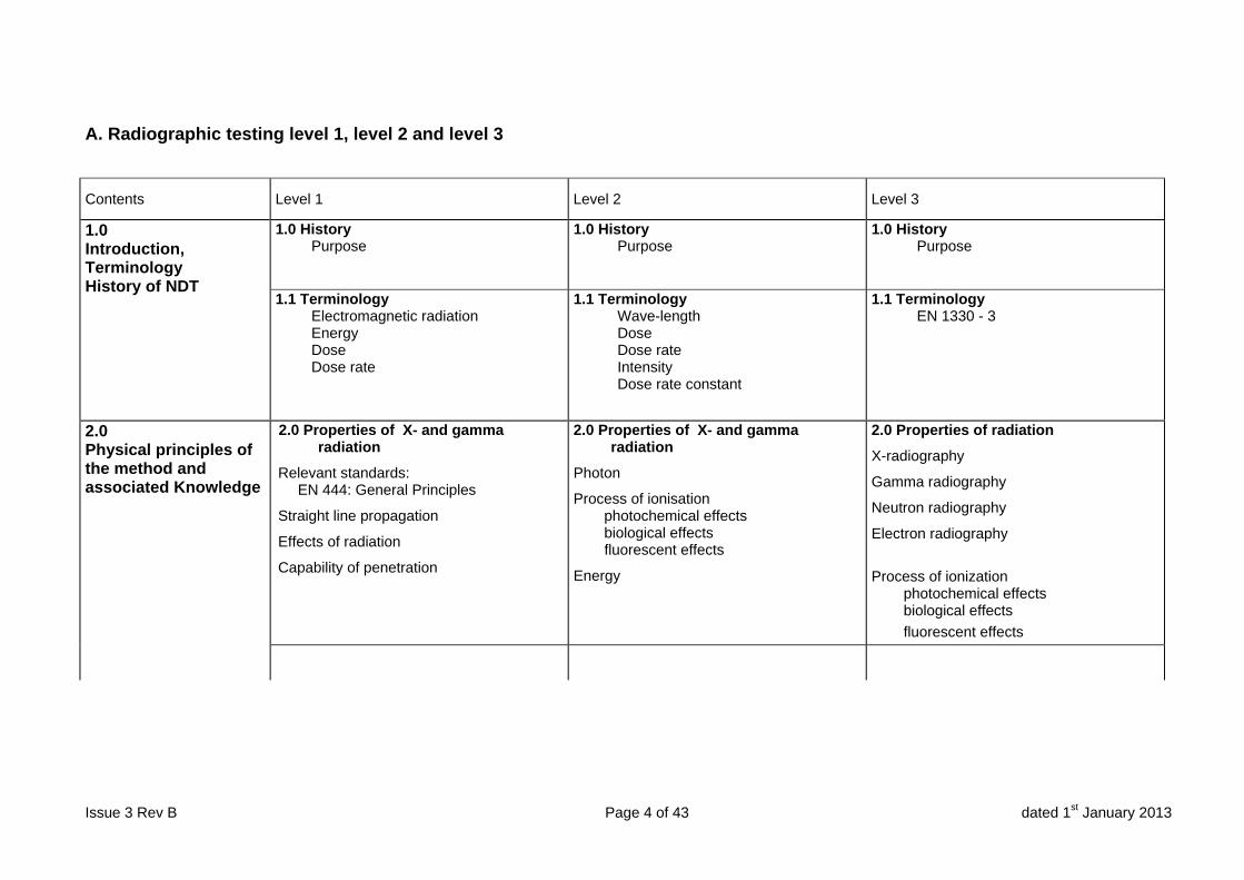
A. Radiographic testing level 1, level 2 and level 3
Contents Level 1 Level 2 Level 3
1.0 Introduction, Terminology History of NDT
1.0 History Purpose
1.0 History Purpose
1.0 History Purpose
1.1 Terminology Electromagnetic radiation Energy Dose Dose rate
1.1 Terminology Wave-length Dose Dose rate Intensity Dose rate constant
1.1 Terminology EN 1330 - 3
2.0 Physical principles of the method and associated Knowledge
2.0 Properties of X- and gamma radiation
Relevant standards: EN 444: General Principles
Straight line propagation
Effects of radiation
Capability of penetration
2.0 Properties of X- and gamma radiation
Photon
Process of ionisation photochemical effects biological effects fluorescent effects
Energy
2.0 Properties of radiation
X-radiography
Gamma radiography
Neutron radiography
Electron radiography
Process of ionization
photochemical effects biological effects
fluorescent effects
Contents Level 1 Level 2 Level 3
Issue 3 Rev B Page 5 of 43 dated 1st January 2013
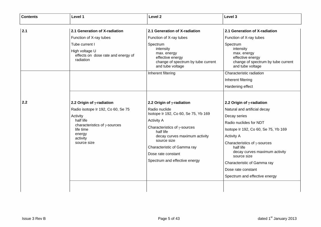
2.1 2.1 Generation of X-radiation
Function of X-ray tubes
Tube current I
High voltage U effects on dose rate and energy of radiation
2.1 Generation of X-radiation
Function of X-ray tubes
Spectrum intensity max. energy effective energy change of spectrum by tube current and tube voltage
2.1 Generation of X-radiation
Function of X-ray tubes
Spectrum intensity max. energy effective energy change of spectrum by tube current and tube voltage
Inherent filtering Characteristic radiation
Inherent filtering
Hardening effect
2.2 2.2 Origin of -radiation
Radio isotope Ir 192, Co 60, Se 75
Activity half life characteristics of -sources life time energy activity source size
2.2 Origin of -radiation
Radio nuclide Isotope Ir 192, Co 60, Se 75, Yb 169
Activity A
Characteristics of -sources half life decay curves maximum activity source size
Characteristic of Gamma ray
Dose rate constant
Spectrum and effective energy
2.2 Origin of -radiation
Natural and artificial decay
Decay series
Radio nuclides for NDT
Isotope Ir 192, Co 60, Se 75, Yb 169
Activity A
Characteristics of -sources half life decay curves maximum activity source size
Characteristic of Gamma ray
Dose rate constant
Spectrum and effective energy
Contents Level 1 Level 2 Level 3
Issue 3 Rev B Page 6 of 43 dated 1st January 2013
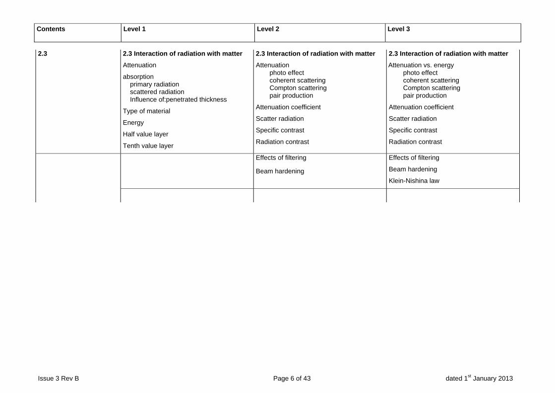
2.3 2.3 Interaction of radiation with matter
Attenuation
absorption primary radiation scattered radiation Influence of:penetrated thickness
Type of material
Energy
Half value layer
Tenth value layer
2.3 Interaction of radiation with matter
Attenuation photo effect coherent scattering Compton scattering pair production
Attenuation coefficient
Scatter radiation
Specific contrast
Radiation contrast
2.3 Interaction of radiation with matter
Attenuation vs. energy photo effect coherent scattering Compton scattering pair production
Attenuation coefficient
Scatter radiation
Specific contrast
Radiation contrast
Effects of filtering
Beam hardening
Effects of filtering
Beam hardening
Klein-Nishina law
Contents Level 1 Level 2 Level 3
Issue 3 Rev B Page 7 of 43 dated 1st January 2013
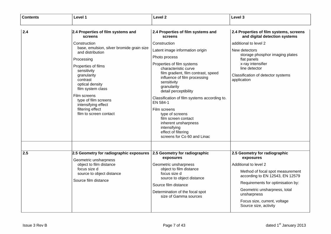
2.4 2.4 Properties of film systems and screens
Construction base, emulsion, silver bromide grain size and distribution
Processing
Properties of films sensitivity granularity contrast optical density film system class
Film screens type of film screens intensifying effect filtering effect film to screen contact
2.4 Properties of film systems and screens
Construction
Latent image information origin
Photo process
Properties of film systems characteristic curve film gradient, film contrast, speed influence of film processing sensitivity granularity detail perceptibility
Classification of film systems according to. EN 584-1
Film screens type of screens film screen contact inherent unsharpness intensifying effect of filtering screens for Co 60 and Linac
2.4 Properties of film systems, screens and digital detection systems
additional to level 2
New detectors storage phosphor imaging plates flat panels x-ray intensifier line detector
Classification of detector systems application
2.5 2.5 Geometry for radiographic exposures
Geometric unsharpness object to film distance focus size d source to object distance
Source film distance
2.5 Geometry for radiographic exposures
Geometric unsharpness object to film distance focus size d source to object distance
Source film distance
Determination of the focal spot size of Gamma sources
2.5 Geometry for radiographic exposures
Additional to level 2
Method of focal spot measurement according to EN 12543, EN 12579
Requirements for optimisation by:
Geometric unsharpness, total unsharpness
Focus size, current, voltage Source size, activity

Contents Level 1 Level 2 Level 3
Issue 3 Rev B Page 8 of 43 dated 1st January 2013
3.0 Product knowledge and capabilities of the method and its derivate Techniques
3.0 Typical weld defects imperfections
Type of discontinuity according. to EN ISO 6520
3.0 Weld imperfections
Type of weld seam and weld seam preparation
Welding process origin
Type of discontinuity according to EN ISO 6520
3.0 Weld imperfections
Additional to level 2 Introduction to fracture mechanics working load
Materials properties
Origin of defects
Further NDT methods
3.1 3.1Typical defects in castings
Types of defects
3.1 Defects in castings
Casting process
Types of cast imperfections and their origin
Structural indications
Beam direction to detectability
3.1 Defects in castings
Casting process
Type of cast imperfections and their origin
Structural indications
Working load
Materials properties
Production caused defects
3.2 3.2 Influence to detectability
type of defect, size orientation
Imaged thickness range
Number of exposures
3.2 Influence to detectability
beam direction geometric distortion increase in wall thickness
Imaged thickness range
Thickness ranges for x- and -rays
Number of exposures
3.2 Influence to detectability
beam direction geometric distortion increase in wall thickness
Imaged thickness range
Thickness ranges for x- and -rays
Number of exposures vs. distortion angle

Contents Level 1 Level 2 Level 3
Issue 3 Rev B Page 9 of 43 dated 1st January 2013
4.0 Equipment
4.0 Design and Operation of X-ray Machines
Stationary systems, mobile unit
Tubes glass- and metal-ceramic tube
Design of tubes standard tube rod anode tube short anode tube
Cooling: Gas, water, oil
Focal spot
High voltage, max. current
Exposure time
Diaphragm
Safety circuit
Operation instructions
4.0 Design and Operation of X-ray Machines
Additional to level 1:
inherent filtering pre-filtering
Devices for special applications micro focus tubes enlargement technique radioscopy
Linac
Construction
Field of application
Typical dates
4.0 Design and Operation of X-ray Machines
Additional to level 2
beam opening characteristics x-ray flash devices rod anode devices micro focus devices high voltage devices
Line focus tubes
Rotary anode tubes
4.1 4.1 Design and Operation of Gamma ray Devices
container, shielding class: P, M type: A, B (transportation) source holder and source capsule
Enclosed radioactive material manipulation device connections accessory remote control collimation fittings
Operation instructions
Reference to national requirements and safety regulations
4.1 Design and Operation of Gamma ray Devices
Additional to level 1:
crawler for pipelines special device for testing of heat exchanger tubes
4.1 Design and Operation of Gamma ray Devices
Same as level 2
Contents Level 1 Level 2 Level 3
Issue 3 Rev B Page 10 of 43 dated 1st January 2013
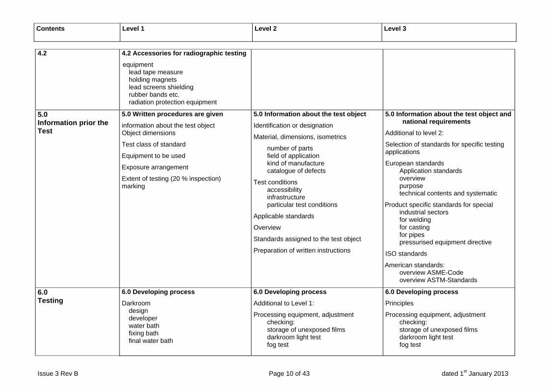
4.2 4.2 Accessories for radiographic testing
equipment lead tape measure holding magnets lead screens shielding rubber bands etc. radiation protection equipment
5.0 Information prior the Test
5.0 Written procedures are given
information about the test object Object dimensions
Test class of standard
Equipment to be used
Exposure arrangement
Extent of testing (20 % inspection) marking
5.0 Information about the test object
Identification or designation
Material, dimensions, isometrics
number of parts field of application kind of manufacture catalogue of defects
Test conditions accessibility infrastructure particular test conditions
Applicable standards
Overview
Standards assigned to the test object
Preparation of written instructions
5.0 Information about the test object and national requirements
Additional to level 2:
Selection of standards for specific testing applications
European standards Application standards overview purpose technical contents and systematic
Product specific standards for special industrial sectors for welding for casting for pipes pressurised equipment directive
ISO standards
American standards: overview ASME-Code overview ASTM-Standards
6.0 Testing
6.0 Developing process
Darkroom design developer water bath fixing bath final water bath
6.0 Developing process
Additional to Level 1:
Processing equipment, adjustment checking: storage of unexposed films darkroom light test fog test
6.0 Developing process
Principles
Processing equipment, adjustment checking: storage of unexposed films darkroom light test fog test
Contents Level 1 Level 2 Level 3
Issue 3 Rev B Page 11 of 43 dated 1st January 2013
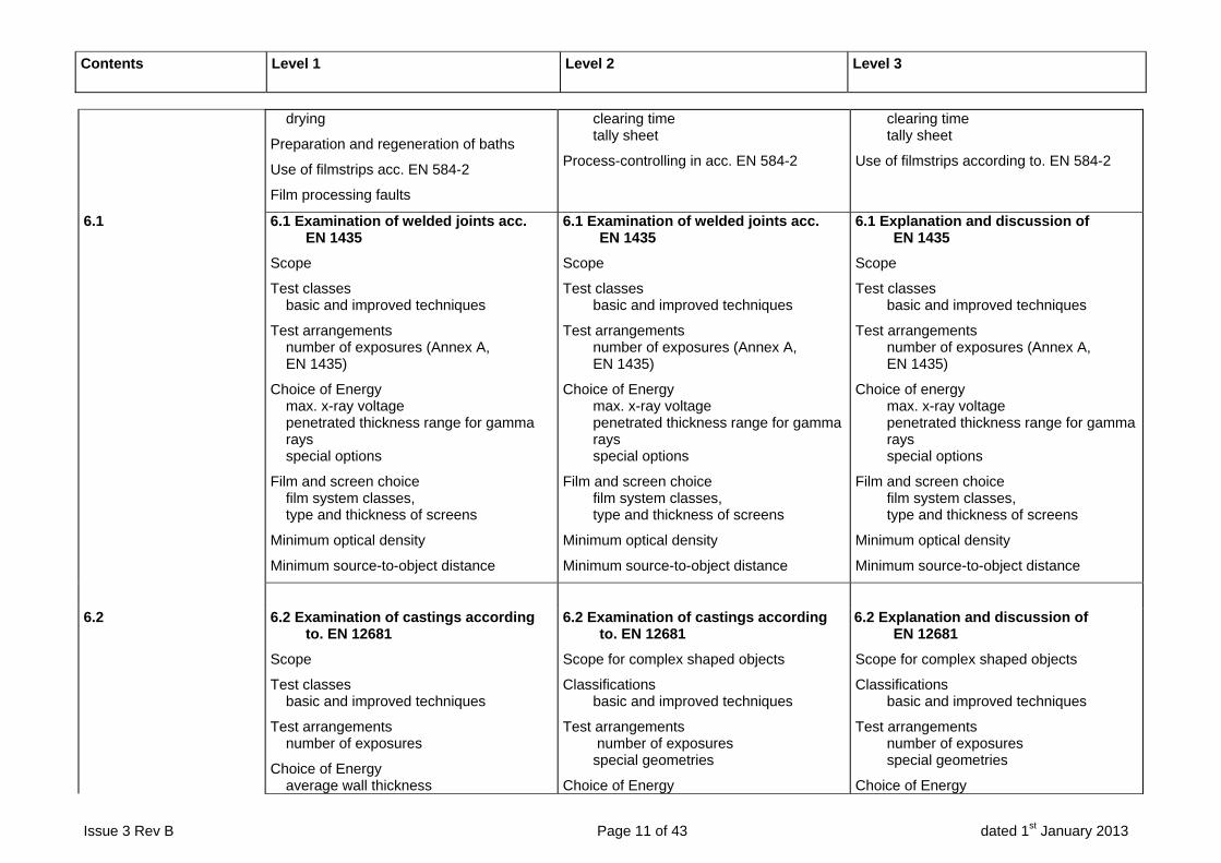
drying
Preparation and regeneration of baths
Use of filmstrips acc. EN 584-2
Film processing faults
clearing time tally sheet
Process-controlling in acc. EN 584-2
clearing time tally sheet
Use of filmstrips according to. EN 584-2
6.1 6.1 Examination of welded joints acc. EN 1435
Scope
Test classes basic and improved techniques
Test arrangements number of exposures (Annex A, EN 1435)
Choice of Energy max. x-ray voltage penetrated thickness range for gamma rays special options
Film and screen choice film system classes, type and thickness of screens
Minimum optical density
Minimum source-to-object distance
6.1 Examination of welded joints acc. EN 1435
Scope
Test classes basic and improved techniques
Test arrangements number of exposures (Annex A, EN 1435)
Choice of Energy max. x-ray voltage penetrated thickness range for gamma rays special options
Film and screen choice film system classes, type and thickness of screens
Minimum optical density
Minimum source-to-object distance
6.1 Explanation and discussion of EN 1435
Scope
Test classes basic and improved techniques
Test arrangements number of exposures (Annex A, EN 1435)
Choice of energy max. x-ray voltage penetrated thickness range for gamma rays special options
Film and screen choice film system classes, type and thickness of screens
Minimum optical density
Minimum source-to-object distance
6.2 6.2 Examination of castings according to. EN 12681
Scope
Test classes basic and improved techniques
Test arrangements number of exposures
Choice of Energy average wall thickness
6.2 Examination of castings according to. EN 12681
Scope for complex shaped objects
Classifications basic and improved techniques
Test arrangements number of exposures special geometries
Choice of Energy
6.2 Explanation and discussion of EN 12681
Scope for complex shaped objects
Classifications basic and improved techniques
Test arrangements number of exposures special geometries
Choice of Energy

Contents Level 1 Level 2 Level 3
Issue 3 Rev B Page 12 of 43 dated 1st January 2013
max. x-ray voltage penetrated thickness range for gamma rays special options
Film and screen choice film system classes, type and thickness of screens
Minimum optical density
Minimum source-to-object distance film
average wall thickness max. x-ray voltage penetrated thickness range for gamma rays special options
Use of enlargement Double film technique wall thickness compensation use of higher Energy, hardening
Film and screen choice film system classes, type and thickness of screens
minimum optical density
minimum source-to-object distance
average wall thickness max. x-ray voltage penetrated thickness range for gamma rays special options
Increase of covered thickness range Double film technique wall thickness equalization use of higher Energy, hardening
Film and screen choice film system classes, type and thickness of screens
minimum optical density
minimum source-to-object distance
6.3 6.3 Working with Exposure charts
Definition of exposure value exposure time
Correction of exposure time for different Film-focalspot-distance FFD optical density relative film exposure factor
6.3 Special Technique
Stereo technique
Round about technique
Testing of corrosion damage
Enlargement with micro focus
Real-time technique fluorescent screens radioscopy computed radiography documentation, picture archive
6.3 Direct radiography and radioscopy according to. EN 13068
Image detectors: fluoroscope flat panels x-ray intensifier camera and TV-systems
Applications: serial production testing dynamical testing special materials
Limits of the method: resolution dynamic signal-to-noise-ratio modulation transfer function
Basic image processing monitoring documentation

Contents Level 1 Level 2 Level 3
Issue 3 Rev B Page 13 of 43 dated 1st January 2013
6.4 6.4 Special Technique
Stereo technique
Round about technique
Testing of corrosion damage
Enlargement with micro focus
Special aspects for radiography of materials with high and low density
Low voltage radiography
Radiography of art objects light alloys plastics pre filtering
High voltage radiography concrete testing
Film – screen –systems pre filtering intermediate filtering heavy walled casting special radiation protection, contamination
6.5 6.5 Image quality indicators according. to EN 462-1, -2,-3
Definition of Image quality number design of IQI IQI position of different exposures image quality classes image quality number
6.5 Image quality indicators according to EN 462-1, -2,-3
Additional to Level 1:
Image quality number for other materials acc. EN 462-4 Detection of unsharpness with duplex-indicator acc. EN 462-5
6.5 Image quality indicators according to EN 462-1, -2,-3, 4, 5
Same as Level 2:
Relevance of image quality indicators
International image quality indicators
6.6 6.6 System of marking
object to film assignment permanent marking of the object, zero point, incremental count direction, marker tape, position of markings on the object
6.6 Drafting an NDT instruction for the testing of welding and castings
Organization of simple test procedures
Test objects ambient conditions reference documents, specifications, standards
6.6 Drafting an NDT procedure for the testing of welding and castings
Complete organization of test procedures in combination with other NDT-methods
Integration of internal priorities
Choice of testing method time of testing
Contents Level 1 Level 2 Level 3
Issue 3 Rev B Page 14 of 43 dated 1st January 2013
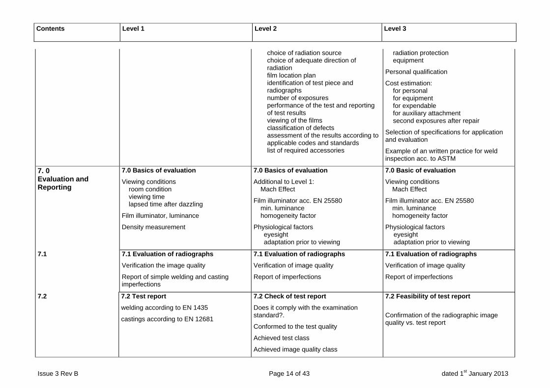
choice of radiation source choice of adequate direction of radiation film location plan identification of test piece and radiographs number of exposures performance of the test and reporting of test results viewing of the films classification of defects assessment of the results according to applicable codes and standards list of required accessories
radiation protection equipment
Personal qualification
Cost estimation: for personal for equipment for expendable for auxiliary attachment second exposures after repair
Selection of specifications for application and evaluation
Example of an written practice for weld inspection acc. to ASTM
7. 0 Evaluation and Reporting
7.0 Basics of evaluation
Viewing conditions room condition viewing time lapsed time after dazzling
Film illuminator, luminance
Density measurement
7.0 Basics of evaluation
Additional to Level 1: Mach Effect
Film illuminator acc. EN 25580 min. luminance homogeneity factor
Physiological factors eyesight adaptation prior to viewing
7.0 Basic of evaluation
Viewing conditions Mach Effect
Film illuminator acc. EN 25580 min. luminance homogeneity factor
Physiological factors eyesight adaptation prior to viewing
7.1 7.1 Evaluation of radiographs
Verification the image quality
Report of simple welding and casting imperfections
7.1 Evaluation of radiographs
Verification of image quality
Report of imperfections
7.1 Evaluation of radiographs
Verification of image quality
Report of imperfections
7.2 7.2 Test report
welding according to EN 1435
castings according to EN 12681
7.2 Check of test report
Does it comply with the examination standard?.
Conformed to the test quality
Achieved test class
Achieved image quality class
7.2 Feasibility of test report
Confirmation of the radiographic image quality vs. test report

Contents Level 1 Level 2 Level 3
Issue 3 Rev B Page 15 of 43 dated 1st January 2013
Achieved diagnostic coverage of test object
8.0 Assessment
8.0 Classification of imperfections
Type, size, localisation, frequency
8.0 Classification of imperfections
Type, size, localisation, frequency
8.1 Assessment of imperfections
Welding according to EN 25817 according to 12062 according to. EN 12517, according to Standard on inspection of pressure vessels (EN 13445-5)
casting according to ASTM
Evaluation catalogue to EN 25817
ASTM – catalogue
other national training catalogues
influence of manufacture and material
8.1 Assessment of imperfections
Welding according to ISO 6520 according to EN 25817 according to 12062 according to EN 12517, according to standard on inspection of pressure vessels (EN 13445-5)
casting according to ASTM
Evaluation catalogue to EN 25817
ASTM – catalogue
other national training catalogues
influence of manufacture and material
9.0 Quality aspects
9.0 Personnel qualification (according to EN ISO 9712)
Equipment verification
9.0 Personnel qualification (according to EN ISO 9712)
Equipment verification
Written instructions
Traceability of documents
A review of applicable NDT application and product standards
9.0 Personnel qualification (according to EN ISO 9712)
Equipment verification
Format of working procedures,
Traceability of documents
Other NDT qualification and certification systems
A review of applicable NDT application and product standards
Contents Level 1 Level 2 Level 3
Issue 3 Rev B Page 16 of 43 dated 1st January 2013
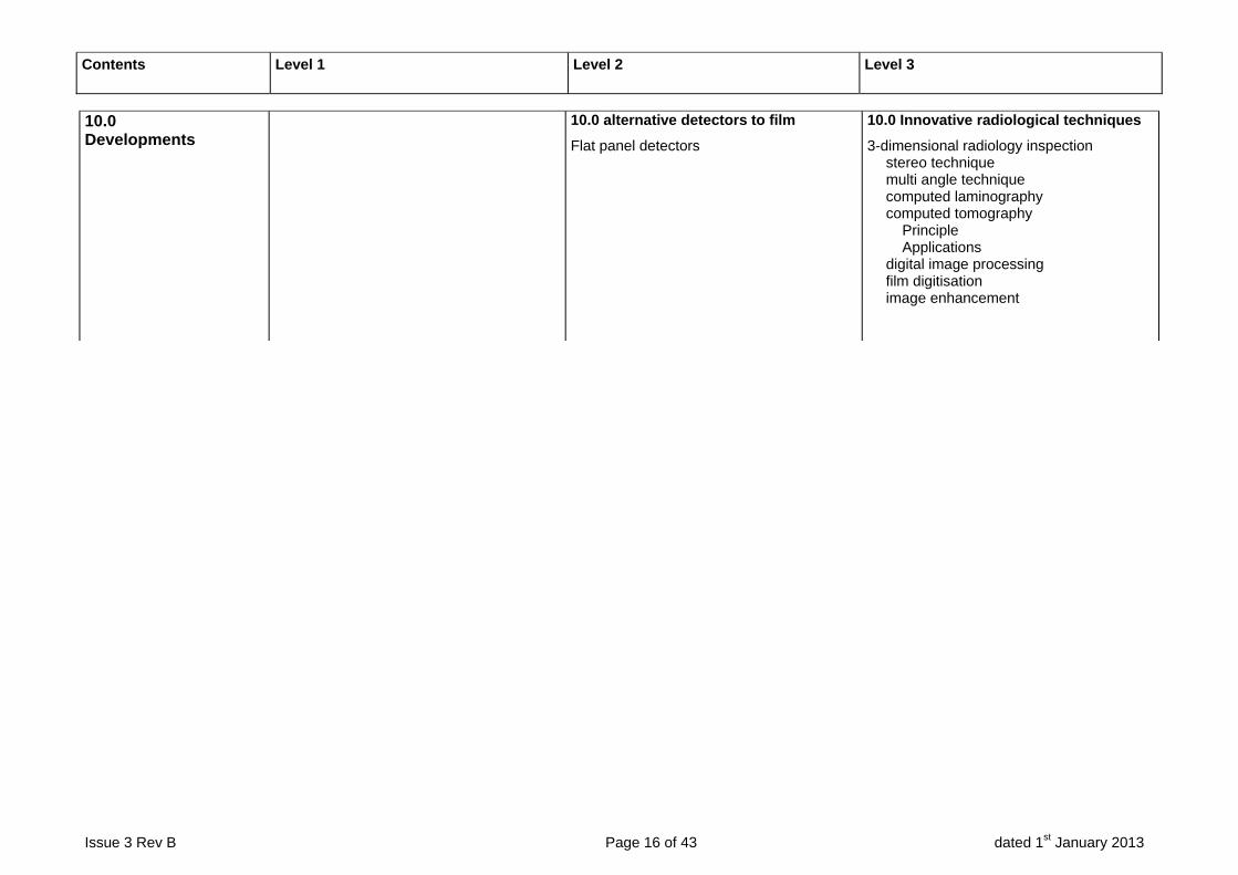
10.0 Developments
10.0 alternative detectors to film
Flat panel detectors
10.0 Innovative radiological techniques
3-dimensional radiology inspection stereo technique multi angle technique computed laminography computed tomography Principle Applications digital image processing film digitisation image enhancement
Issue 3 Rev B Page 17 of 43 dated 1st January 2013
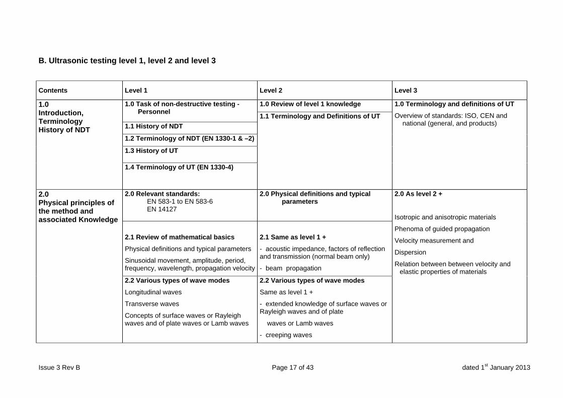
B. Ultrasonic testing level 1, level 2 and level 3
Contents Level 1 Level 2 Level 3
1.0 Introduction, Terminology History of NDT
1.0 Task of non-destructive testing - Personnel
1.0 Review of level 1 knowledge 1.0 Terminology and definitions of UT
Overview of standards: ISO, CEN and national (general, and products)
1.1 Terminology and Definitions of UT
1.1 History of NDT
1.2 Terminology of NDT (EN 1330-1 & –2)
1.3 History of UT
1.4 Terminology of UT (EN 1330-4)
2.0 Physical principles of the method and associated Knowledge
2.0 Relevant standards: EN 583-1 to EN 583-6 EN 14127
2.0 Physical definitions and typical parameters
2.0 As level 2 +
Isotropic and anisotropic materials
Phenoma of guided propagation
Velocity measurement and
Dispersion
Relation between between velocity and elastic properties of materials
2.1 Review of mathematical basics
Physical definitions and typical parameters
Sinusoidal movement, amplitude, period, frequency, wavelength, propagation velocity
2.1 Same as level 1 +
- acoustic impedance, factors of reflection and transmission (normal beam only)
- beam propagation
2.2 Various types of wave modes
Longitudinal waves
Transverse waves
Concepts of surface waves or Rayleigh waves and of plate waves or Lamb waves
2.2 Various types of wave modes
Same as level 1 +
- extended knowledge of surface waves or Rayleigh waves and of plate
waves or Lamb waves
- creeping waves
Contents Level 1 Level 2 Level 3
Issue 3 Rev B Page 18 of 43 dated 1st January 2013
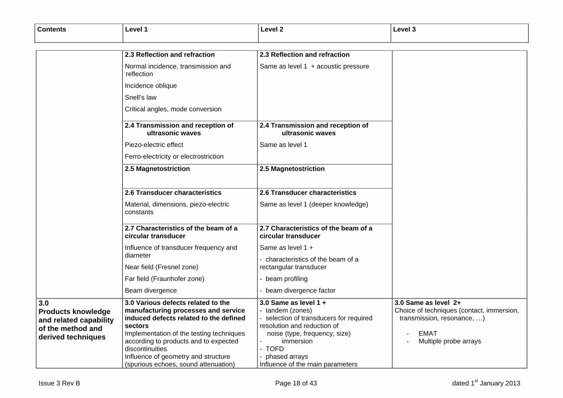
2.3 Reflection and refraction
Normal incidence, transmission and reflection
Incidence oblique
Snell’s law
Critical angles, mode conversion
2.3 Reflection and refraction
Same as level 1 + acoustic pressure
2.4 Transmission and reception of ultrasonic waves
Piezo-electric effect
Ferro-electricity or electrostriction
2.4 Transmission and reception of ultrasonic waves
Same as level 1
2.5 Magnetostriction
2.5 Magnetostriction
2.6 Transducer characteristics
Material, dimensions, piezo-electric constants
2.6 Transducer characteristics
Same as level 1 (deeper knowledge)
2.7 Characteristics of the beam of a circular transducer
Influence of transducer frequency and diameter
Near field (Fresnel zone)
Far field (Fraunhofer zone)
Beam divergence
2.7 Characteristics of the beam of a circular transducer
Same as level 1 +
- characteristics of the beam of a rectangular transducer
- beam profiling
- beam divergence factor
3.0 Products knowledge and related capability of the method and derived techniques
3.0 Various defects related to the manufacturing processes and service induced defects related to the defined sectors Implementation of the testing techniques according to products and to expected discontinuities Influence of geometry and structure (spurious echoes, sound attenuation)
3.0 Same as level 1 + - tandem (zones) - selection of transducers for required resolution and reduction of noise (type, frequency, size) - immersion - TOFD - phased arrays Influence of the main parameters
3.0 Same as level 2+ Choice of techniques (contact, immersion,
transmission, resonance, …)
- EMAT - Multiple probe arrays

Contents Level 1 Level 2 Level 3
Issue 3 Rev B Page 19 of 43 dated 1st January 2013
A comprehensive understanding and knowledge of the manufacturing processes and associated metallurgy & flaw types etc… A comprehensive understanding and knowledge of the cause and formation of in-service defects including associated metallurgy & flaw types etc…
4.0 Equipment
4.0 Various probes (normal, angle, dual) Instruments (analogical and digital) Pulse generation Reception and amplification (percentage and dB) Range setting A- scan presentation B- and C-scan presentation Additional functions: Couplant
4.0 Same as level 1 + - detailed knowledge of the different functions of UT test equipment - automatic and semi automatic systems - B- and C-scan presentation (deeper knowledge) - couplant (deeper knowledge) Calibration reference and transfer blocks
4.0 Same as level 2 + Systems (manual/semi-automatic,
automatic,): speed, incrementation, repeatability, …
Analog flaw detedors (different circuits) Digital flaw detectors (Comparison with
analog flaw detectors, Sampling-rate) Special equipment including thickness
measurment Probes - Dynamic range - Probes for immersion: focused,
spherical, cylindrical, Fermat surface; - Measurement of pulse length practical
mesurement of the near field Shoe (delay, curvature, …); Connecting cables (sealing, insulation and
flexibility; Blocks: representativity
5.0 Information prior to test
5.0 Written instruction (prepared by a level 2 or 3) Objectives Requirements
5.0 Same as level 1 (deeper knowledge)+- contents and requirements of instructions,
procedures and standards - - Preparation of written instructions
5.0 As level 2 + Selection of technical parameters:
- Products: geometry, surface quality, accessibility, environment, …
- UT indication/ discontinuity/ defect: type, origin, shape, dimension, orientation, tilt/skew, …
- properties of the equipment: Preparation of written specifications

Contents Level 1 Level 2 Level 3
Issue 3 Rev B Page 20 of 43 dated 1st January 2013
6.0 Testing
6.0 Verification of combined equipment according to EN 12668-3
6.0 Same as level 1 (deeper knowledge) +
- reference reflectors (laws of distance and size) - DGS-method - DAC-curves - distance/amplitude-correction - transfer correction (surface and attenuation) - sizing techniques, principles and limitations - scanning
6.0 Same as level 2 + Control and assessment of procedures and
instructions for their efficiency
6.1 Standardized calibration blocks ref : EN 12223 & EN 27963
6.2 Contact technique (straight and angle beam) Reflection Transmission
6.3 Immersion techniques (straight and angle beam) Reflection Transmission
6.4 Setting of range and sensitivity Reference reflectors Transfer correction
6.5 Ultrasonic thickness measurement Equipment Techniques
7.0 Evaluation and reporting
7.0 Detecting, locating (trigonometrical rules) and sizing techniques Recording and evaluation level Acceptance levels Test reports System of coordinate Measurement (probe, reflector) Calculated values
7.0 Same as level 1 (deeper knowledge)+ - characterization (planar / non planar
according to EN 1713 for welds) - Interpretation and evaluation of indications
7.0 Use of complementary NDT methods;
Interpretation of relevant standards and codes
Evaluation (conventional approach, validated method) ;
Distinction defect/artefact; Acceptance criteria; Level of significant variation; Storage and recording process
Contents Level 1 Level 2 Level 3
Issue 3 Rev B Page 21 of 43 dated 1st January 2013
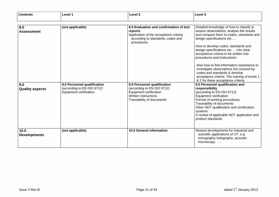
8.0 Assessment
(not applicable) 8.0 Evaluation and confirmation of test reports Application of the acceptance criteria
according to standards, codes and procedures
Detailed knowledge of how to classify & assess observations, analyse the results and compare them to codes, standards and design specifications etc…. How to develop codes, standards and design specifications etc…. into clear acceptance criteria to be written into procedures and instructions Also how to find information /assistance to investigate observations not covered by codes and standards & develop acceptance criteria. The training of levels 1 & 2 for these acceptance criteria.
9.0 Quality aspects
9.0 Personnel qualification (according to EN ISO 9712) Equipment verification
9.0 Personnel qualification (according to EN ISO 9712) Equipment verification Written instructions Traceability of documents
9.0 Personnel qualification and responsibility (according to EN ISO 9712) Equipment verification Format of working procedures, Traceability of documents Other NDT qualification and certification systems A review of applicable NDT application and product standards
10.0 Developments
(not applicable) 10.0 General information Newest developments for industrial and scientific applications of UT: e.g. tomography holography, acoustic microscopy, …
Issue 3 Rev B Page 22 of 43 dated 1st January 2013
C. Eddy current testing level 1, level 2 and level 3
Contents Level 1 Level 2 Level 3
1.0 Introduction, Terminology, History of NDT
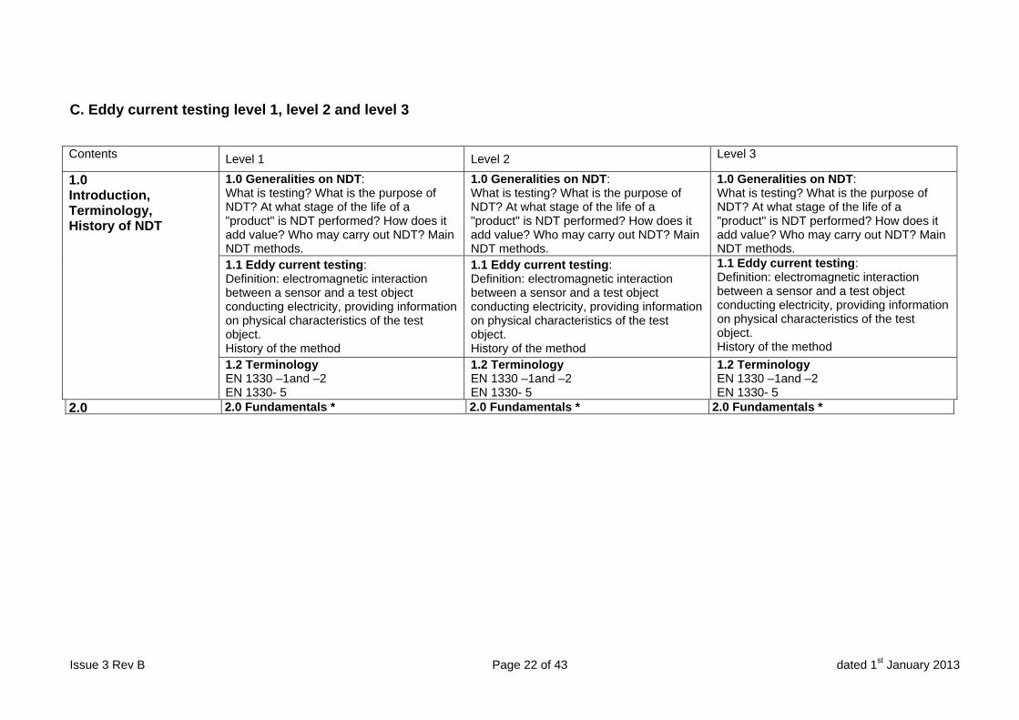
1.0 Generalities on NDT: What is testing? What is the purpose of NDT? At what stage of the life of a "product" is NDT performed? How does it add value? Who may carry out NDT? Main NDT methods.
1.0 Generalities on NDT: What is testing? What is the purpose of NDT? At what stage of the life of a "product" is NDT performed? How does it add value? Who may carry out NDT? Main NDT methods.
1.0 Generalities on NDT: What is testing? What is the purpose of NDT? At what stage of the life of a "product" is NDT performed? How does it add value? Who may carry out NDT? Main NDT methods.
1.1 Eddy current testing: Definition: electromagnetic interaction between a sensor and a test object conducting electricity, providing information on physical characteristics of the test object. History of the method
1.1 Eddy current testing: Definition: electromagnetic interaction between a sensor and a test object conducting electricity, providing information on physical characteristics of the test object. History of the method
1.1 Eddy current testing: Definition: electromagnetic interaction between a sensor and a test object conducting electricity, providing information on physical characteristics of the test object. History of the method
1.2 Terminology EN 1330 –1and –2 EN 1330- 5
1.2 Terminology EN 1330 –1and –2 EN 1330- 5
1.2 Terminology EN 1330 –1and –2 EN 1330- 5
2.0 2.0 Fundamentals * 2.0 Fundamentals * 2.0 Fundamentals *
Contents Level 1 Level 2 Level 3
Issue 3 Rev B Page 23 of 43 dated 1st January 2013
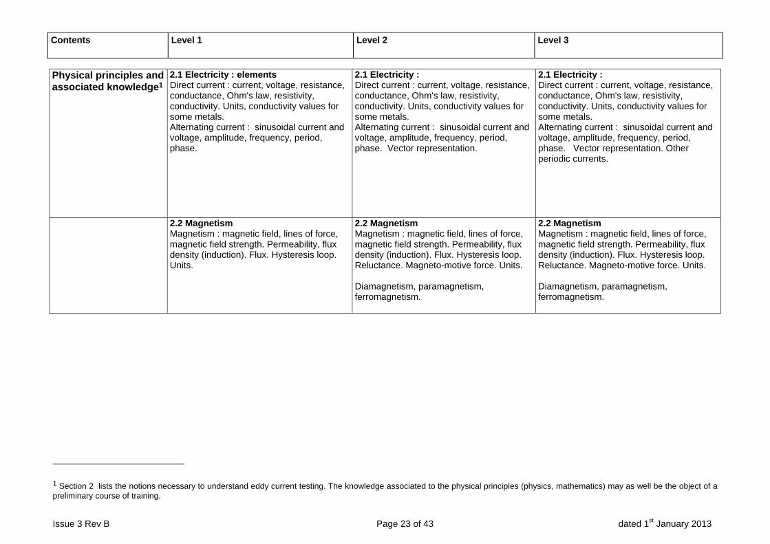
Physical principles and associated knowledge1
2.1 Electricity : elements Direct current : current, voltage, resistance, conductance, Ohm's law, resistivity, conductivity. Units, conductivity values for some metals. Alternating current : sinusoidal current and voltage, amplitude, frequency, period, phase.
2.1 Electricity : Direct current : current, voltage, resistance, conductance, Ohm's law, resistivity, conductivity. Units, conductivity values for some metals. Alternating current : sinusoidal current and voltage, amplitude, frequency, period, phase. Vector representation.
2.1 Electricity : Direct current : current, voltage, resistance, conductance, Ohm's law, resistivity, conductivity. Units, conductivity values for some metals. Alternating current : sinusoidal current and voltage, amplitude, frequency, period, phase. Vector representation. Other periodic currents.
2.2 Magnetism Magnetism : magnetic field, lines of force, magnetic field strength. Permeability, flux density (induction). Flux. Hysteresis loop. Units.
2.2 Magnetism Magnetism : magnetic field, lines of force, magnetic field strength. Permeability, flux density (induction). Flux. Hysteresis loop. Reluctance. Magneto-motive force. Units. Diamagnetism, paramagnetism, ferromagnetism.
2.2 Magnetism Magnetism : magnetic field, lines of force, magnetic field strength. Permeability, flux density (induction). Flux. Hysteresis loop. Reluctance. Magneto-motive force. Units. Diamagnetism, paramagnetism, ferromagnetism.
1 Section 2 lists the notions necessary to understand eddy current testing. The knowledge associated to the physical principles (physics, mathematics) may as well be the object of a preliminary course of training.
Contents Level 1 Level 2 Level 3
Issue 3 Rev B Page 24 of 43 dated 1st January 2013
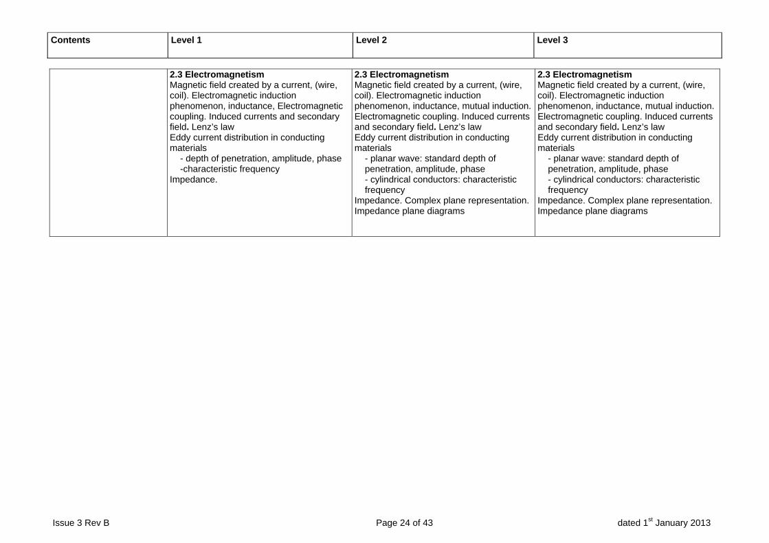
2.3 Electromagnetism Magnetic field created by a current, (wire, coil). Electromagnetic induction phenomenon, inductance, Electromagnetic coupling. Induced currents and secondary field. Lenz’s law Eddy current distribution in conducting materials
- depth of penetration, amplitude, phase -characteristic frequency
Impedance.
2.3 Electromagnetism Magnetic field created by a current, (wire, coil). Electromagnetic induction phenomenon, inductance, mutual induction. Electromagnetic coupling. Induced currents and secondary field. Lenz’s law Eddy current distribution in conducting materials
- planar wave: standard depth of penetration, amplitude, phase - cylindrical conductors: characteristic frequency
Impedance. Complex plane representation. Impedance plane diagrams
Contents Level 1 Level 2 Level 3
Issue 3 Rev B Page 25 of 43 dated 1st January 2013
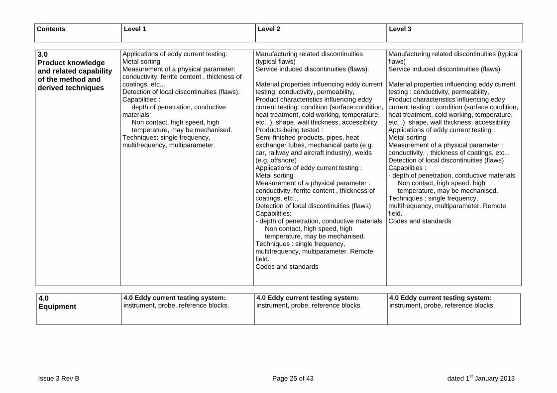
3.0 Product knowledge and related capability of the method and derived techniques
Applications of eddy current testing: Metal sorting Measurement of a physical parameter: conductivity, ferrite content , thickness of coatings, etc... Detection of local discontinuities (flaws). Capabilities : depth of penetration, conductive materials
Non contact, high speed, high temperature, may be mechanised.
Techniques: single frequency, multifrequency, multiparameter.
Manufacturing related discontinuities (typical flaws) Service induced discontinuities (flaws). Material properties influencing eddy current testing: conductivity, permeability, Product characteristics influencing eddy current testing: condition (surface condition, heat treatment, cold working, temperature, etc...), shape, wall thickness, accessibility Products being tested : Semi-finished products, pipes, heat exchanger tubes, mechanical parts (e.g. car, railway and aircraft industry), welds (e.g. offshore) Applications of eddy current testing : Metal sorting Measurement of a physical parameter : conductivity, ferrite content , thickness of coatings, etc... Detection of local discontinuities (flaws) Capabilities: - depth of penetration, conductive materials
Non contact, high speed, high temperature, may be mechanised.
Techniques : single frequency, multifrequency, multiparameter. Remote field. Codes and standards
Manufacturing related discontinuities (typical flaws) Service induced discontinuities (flaws). Material properties influencing eddy current testing : conductivity, permeability, Product characteristics influencing eddy current testing : condition (surface condition, heat treatment, cold working, temperature, etc...), shape, wall thickness, accessibility Applications of eddy current testing : Metal sorting Measurement of a physical parameter : conductivity, , thickness of coatings, etc... Detection of local discontinuities (flaws) Capabilities : - depth of penetration, conductive materials
Non contact, high speed, high temperature, may be mechanised.
Techniques : single frequency, multifrequency, multiparameter. Remote field. Codes and standards
4.0 Equipment
4.0 Eddy current testing system: instrument, probe, reference blocks.
4.0 Eddy current testing system: instrument, probe, reference blocks.
4.0 Eddy current testing system: instrument, probe, reference blocks.
Contents Level 1 Level 2 Level 3
Issue 3 Rev B Page 26 of 43 dated 1st January 2013
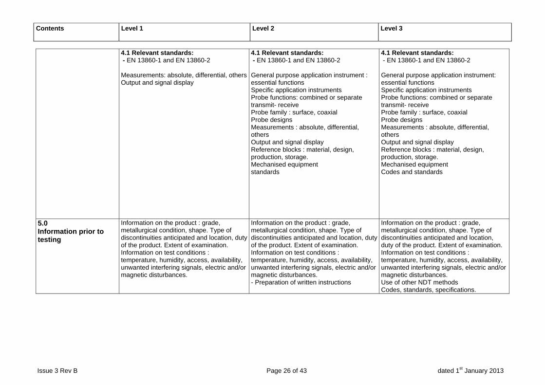
4.1 Relevant standards: - EN 13860-1 and EN 13860-2 Measurements: absolute, differential, othersOutput and signal display
4.1 Relevant standards: - EN 13860-1 and EN 13860-2 General purpose application instrument : essential functions Specific application instruments Probe functions: combined or separate transmit- receive Probe family : surface, coaxial Probe designs Measurements : absolute, differential, others Output and signal display Reference blocks : material, design, production, storage. Mechanised equipment standards
4.1 Relevant standards: - EN 13860-1 and EN 13860-2 General purpose application instrument: essential functions Specific application instruments Probe functions: combined or separate transmit- receive Probe family : surface, coaxial Probe designs Measurements : absolute, differential, others Output and signal display Reference blocks : material, design, production, storage. Mechanised equipment Codes and standards
5.0 Information prior to testing
Information on the product : grade, metallurgical condition, shape. Type of discontinuities anticipated and location, duty of the product. Extent of examination. Information on test conditions : temperature, humidity, access, availability, unwanted interfering signals, electric and/or magnetic disturbances.
Information on the product : grade, metallurgical condition, shape. Type of discontinuities anticipated and location, duty of the product. Extent of examination. Information on test conditions : temperature, humidity, access, availability, unwanted interfering signals, electric and/or magnetic disturbances. - Preparation of written instructions
Information on the product : grade, metallurgical condition, shape. Type of discontinuities anticipated and location, duty of the product. Extent of examination. Information on test conditions : temperature, humidity, access, availability, unwanted interfering signals, electric and/or magnetic disturbances. Use of other NDT methods Codes, standards, specifications.
Contents Level 1 Level 2 Level 3
Issue 3 Rev B Page 27 of 43 dated 1st January 2013
6.0 Testing
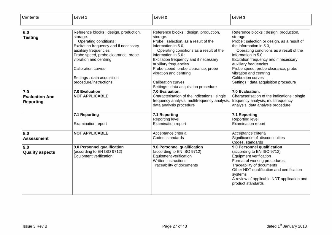
Reference blocks : design, production, storage. Operating conditions : Excitation frequency and if necessary auxiliary frequencies Probe speed, probe clearance, probe vibration and centring Calibration curves Settings : data acquisition procedure/instructions
Reference blocks : design, production, storage. Probe : selection, as a result of the information in 5.0, Operating conditions as a result of the information in 5.0 : Excitation frequency and if necessary auxiliary frequencies Probe speed, probe clearance, probe vibration and centring Calibration curves Settings : data acquisition procedure
Reference blocks : design, production, storage. Probe : selection or design, as a result of the information in 5.0, Operating conditions as a result of the information in 5.0 : Excitation frequency and if necessary auxiliary frequencies Probe speed, probe clearance, probe vibration and centring Calibration curves Settings : data acquisition procedure
7.0 Evaluation And Reporting
7.0 Evaluation NOT APPLICABLE
7.0 Evaluation. Characterisation of the indications : single frequency analysis, multifrequency analysis, data analysis procedure
7.0 Evaluation. Characterisation of the indications : single frequency analysis, multifrequency analysis, data analysis procedure
7.1 Reporting Examination report
7.1 Reporting Reporting level Examination report
7.1 Reporting Reporting level Examination report
8.0 Assessment
NOT APPLICABLE Acceptance criteria Codes, standards
Acceptance criteria Significance of discontinuities Codes, standards
9.0 Quality aspects
9.0 Personnel qualification (according to EN ISO 9712) Equipment verification
9.0 Personnel qualification (according to EN ISO 9712) Equipment verification Written instructions Traceability of documents
9.0 Personnel qualification (according to EN ISO 9712) Equipment verification Format of working procedures, Traceability of documents Other NDT qualification and certification systems A review of applicable NDT application and product standards
Contents Level 1 Level 2 Level 3
Issue 3 Rev B Page 28 of 43 dated 1st January 2013
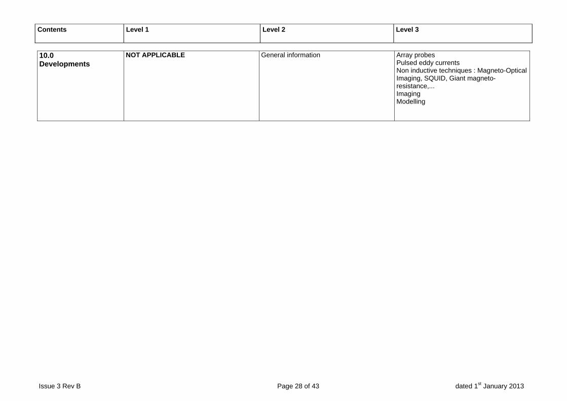
10.0 Developments
NOT APPLICABLE General information Array probes Pulsed eddy currents Non inductive techniques : Magneto-Optical Imaging, SQUID, Giant magneto-resistance,... Imaging Modelling
Issue 3 Rev B Page 29 of 43 dated 1st January 2013
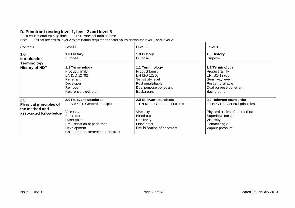
D. Penetrant testing level 1, level 2 and level 3 * E = educational training time P = Practical training time Note "direct access to level 2 examination requires the total hours shown for level 1 and level 2".
Contents Level 1 Level 2 Level 3
1.0 Introduction, Terminology History of NDT
1.0 History Purpose
1.0 History Purpose
1.0 History Purpose
1.1 Terminology Product family EN ISO 12706 Penetrant Developer Remover Reference block e.g.
1.1 Terminology Product family EN ISO 12706 Sensitivity level Post emulsifiable Dual purpose penetrant Background
1.1 Terminology Product family EN ISO 12706 Sensitivity level Post emulsifiable Dual purpose penetrant Background
2.0 Physical principles of the method and associated Knowledge
2.0 Relevant standards: - EN 571-1: General principles Viscosity Bleed out Flash point Emulsification of penetrant Development Coloured and fluorescent penetrant
2.0 Relevant standards: - EN 571-1: General principles Viscosity Bleed out Capillarity Flash point Emulsification of penetrant
2.0 Relevant standards: - EN 571-1: General principles Physical basics of the method Superficial tension Viscosity Contact angle Vapour pressure
Contents Level 1 Level 2 Level 3
Issue 3 Rev B Page 30 of 43 dated 1st January 2013
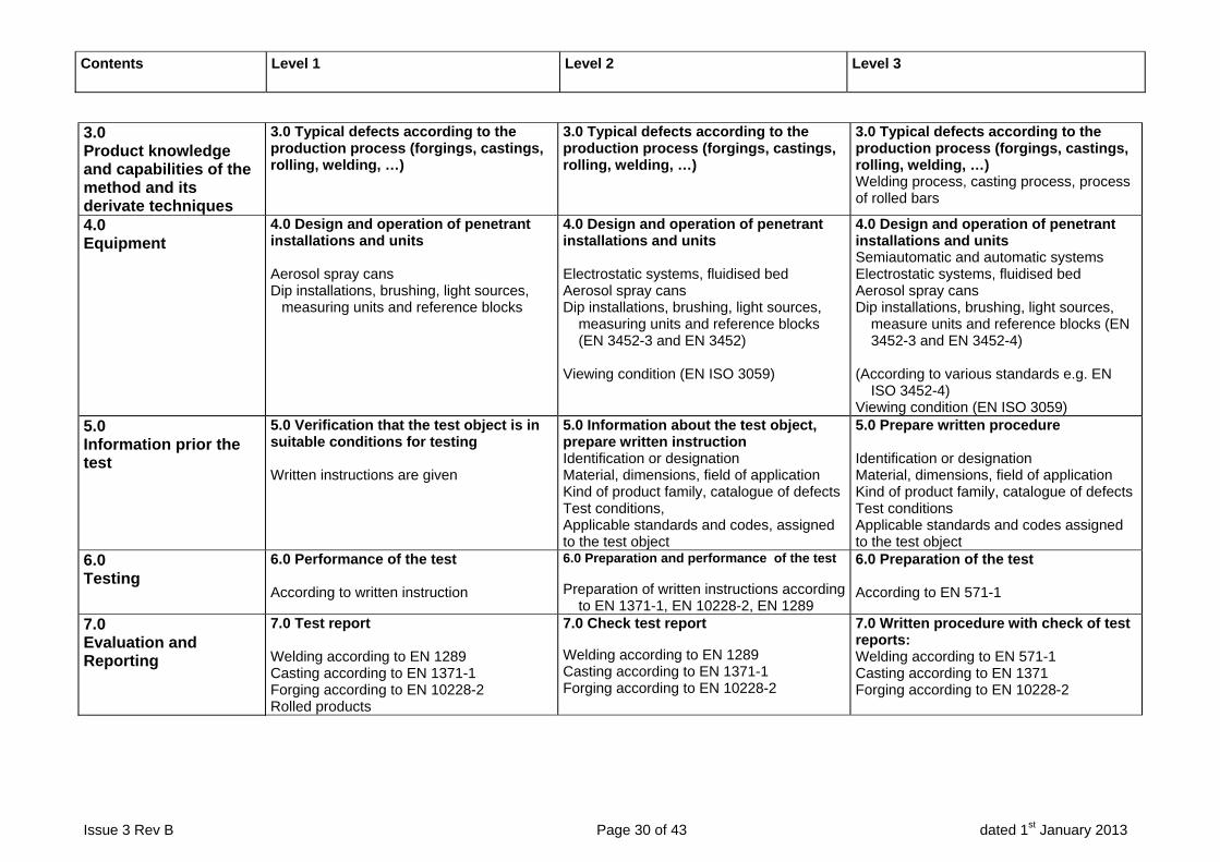
3.0 Product knowledge and capabilities of the method and its derivate techniques
3.0 Typical defects according to the production process (forgings, castings, rolling, welding, …)
3.0 Typical defects according to the production process (forgings, castings, rolling, welding, …)
3.0 Typical defects according to the production process (forgings, castings, rolling, welding, …) Welding process, casting process, process of rolled bars
4.0 Equipment
4.0 Design and operation of penetrant installations and units Aerosol spray cans Dip installations, brushing, light sources,
measuring units and reference blocks
4.0 Design and operation of penetrant installations and units Electrostatic systems, fluidised bed Aerosol spray cans Dip installations, brushing, light sources,
measuring units and reference blocks (EN 3452-3 and EN 3452)
Viewing condition (EN ISO 3059)
4.0 Design and operation of penetrant installations and units Semiautomatic and automatic systems Electrostatic systems, fluidised bed Aerosol spray cans Dip installations, brushing, light sources,
measure units and reference blocks (EN 3452-3 and EN 3452-4)
(According to various standards e.g. EN
ISO 3452-4) Viewing condition (EN ISO 3059)
5.0 Information prior the test
5.0 Verification that the test object is in suitable conditions for testing Written instructions are given
5.0 Information about the test object, prepare written instruction Identification or designation Material, dimensions, field of application Kind of product family, catalogue of defects Test conditions, Applicable standards and codes, assigned to the test object
5.0 Prepare written procedure Identification or designation Material, dimensions, field of application Kind of product family, catalogue of defects Test conditions Applicable standards and codes assigned to the test object
6.0 Testing
6.0 Performance of the test According to written instruction
6.0 Preparation and performance of the test Preparation of written instructions according
to EN 1371-1, EN 10228-2, EN 1289
6.0 Preparation of the test According to EN 571-1
7.0 Evaluation and Reporting
7.0 Test report Welding according to EN 1289 Casting according to EN 1371-1 Forging according to EN 10228-2 Rolled products
7.0 Check test report Welding according to EN 1289 Casting according to EN 1371-1 Forging according to EN 10228-2
7.0 Written procedure with check of test reports: Welding according to EN 571-1 Casting according to EN 1371 Forging according to EN 10228-2

Contents Level 1 Level 2 Level 3
Issue 3 Rev B Page 31 of 43 dated 1st January 2013
7.1 Basics of evaluation Viewing conditions according to EN ISO
3059 Reference block No 2 (according to EN ISO 3452-3)
Verification the indication quality
Report of simple welding, forging, rolled products and casting imperfections
7.1 Basics of evaluation Viewing conditions according to EN ISO
3059 Reference block Nos. 1 and 2 (according to EN ISO 3452-3)
Other used reference blocks Calibration of test units Batch test report
7.1 Basics of evaluation Viewing conditions according to EN ISO
3059 Reference block Nos. 1 and 2 (according to
EN ISO 3452-3) Other used reference blocks Calibration of test units
7.2 Evaluation Verification the indication quality
Report of discontinuities according to EN
1289, EN 1371-1, EN 10228-2
7.2 Evaluation Verification the indication quality
8.0 Assessment
8.0 Assessment of discontinuities Depth, width, shape, position, orientation
8.0 Assessment of discontinuities Influence of manufacture and material
8.0 Assessment of discontinuities Depth, width, shape, position, orientation
9.0 Quality aspects
Personnel qualification (according to EN ISO 9712) Equipment verification
Personnel qualification (according to EN ISO 9712) Equipment verification Written instructions Traceability of documents A review of applicable NDT application and product standards
Personnel qualification (according to EN ISO 9712) Equipment verification Format of working procedures Traceability of documents Other NDT qualification and certification systems A review of applicable NDT application and product standards
10.0 Environmental and safety conditions
10.0 Disposing of chemicals Penetrants Developer Emulsifier Material of process excess removal Safety data sheet
10.0 Disposing of chemicals Penetrants Developer Emulsifier Material of process excess removal Safety data sheet Active carbon method, ultrafiltration methodUV radiation, electrical hazard Disposal is regulated by national regulations
10.0 Disposing of chemicals Penetrants Soluble remover, developer Safety data sheets UV-radiation, electrical hazard A review of applicable NDT application and product standards

Contents Level 1 Level 2 Level 3
Issue 3 Rev B Page 32 of 43 dated 1st January 2013
11.0 Developments
(Not applicable) Special installations Automotive installations (examples)
Creative and innovative special installations Automotive installations (examples) Tube installations

Issue 3 Rev B Page 33 of 43 dated 1st January 2013
E. Magnetic particle testing level 1, level 2 and level 3 * E = educational training time P = Practical training time Note "direct access to level 2 examination requires the total hours shown for level 1 and level 2".
Contents Level 1 Level 2 Level 3
1.0 Introduction, terminology, purpose and history of NDT
1.0 Introduction Presentation of the magnetic particle testing Applicability and limits History Terminology
1.0 Introduction Presentation of the magnetic particle testing Applicability and limits History Terminology
1.0 Introduction Presentation of the magnetic particle testing Applicability and limits History Terminology
2.0 Physical principles and associated knowledge
2.0 Basic physical phenomena in terms of general description Electric circuits, typical values, units Magnetic circuits, typical values, units Magnetic field created by electric circuits Passage of the flux from a magnetic medium to a non magnetic media Magnetic flux of a magnetic discontinuity Influence of depth and orientation of a magnetic discontinuity on its detection Magnetic properties of materials Nonmagnetic materials Magnetic materials. Curie point
2.0 Basic physical phenomena Electric circuits, typical value, units Magnetic circuits, typical value, units Magnetic field created by electric circuits
Indefinite rectilinear conductor Long magnetic coil Short or flat magnetizing coil Passage of the flow of a magnetic in a non magnetic media Continuity of HT Continuity of BN Magnetic flux of a magnetic discontinuity Influence of the geometry (depth, thickness) and of the orientation of a magnetic discontinuity on its detection
Magnetic properties Designation of alloys Non magnetic materials Magnetic materials
Field of application Curie Point Curve of the first magnetization Hysteresis cycle and remarkable points Magnetic properties of steels
2.0 Basics Diamagnetism – Paramagnetism Ferromagnetism – Ferrimagnetism Magnetic fields characterization and measurements Magnetic field H - magnetic Induction B Hysteresis cycle and remarkable points Influence of the temperature on the magnetic properties Principle of magnetic particle testing Influence of the interface between a magnetic medium and a nonmagnetic medium
Continuity of HT Continuity of BN
Influence of the orientation of the discontinuity on magnetic flux Behaviour of a magnetic particle in the vicinity of a magnetic flux Influence of geometry (depth, thickness and orientation) on detectability Magnetic properties of principal ferromagnetic alloys
Magnetic field H, magnetic induction B, relative magnetic permeability µ R , coercitive force Hc, electrical resistance

Contents Level 1 Level 2 Level 3
Issue 3 Rev B Page 34 of 43 dated 1st January 2013
. Influence of composition, heat treatments and work hardening of the steel.
Influence of work hardening. Influence of heat treatment Particular alloys: e.g. Permalloys, Invar, Inconel
3.0 Product knowledge and capabilities of method and its derivate techniques
3.0 Typical discontinuities according to the production process (welds, forgings, castings and roller products
3.0 Typical discontinuities in welds, forgings, castings and roller products and there indications
3.0 Typical discontinuities in welds, forgings, castings and roller products and there indications
3.1 Testing parameters: Magnetization, detection media and test of detection media indication.
3.1 Testing parameters: Magnetization, detection media and test of detection media indication.
3.1 Testing parameters: Magnetization, detection media and test of detection media indication
4.0 Equipment
4.0 Equipment Magnetizing equipment Viewing condition Measurement and calibration Demagnetization
4.0 Equipment Various types
Portable electromagnet Mobile Magnetic benches Automatic and robotized with automatic detection (magnetic leakage field)
4.0 Equipment Mobile or fixed equipment using magnetic flow technique or current flow technique Automatic and robotized with automatic detection (magnetic leakage field)
Contents Level 1 Level 2 Level 3
Issue 3 Rev B Page 35 of 43 dated 1st January 2013
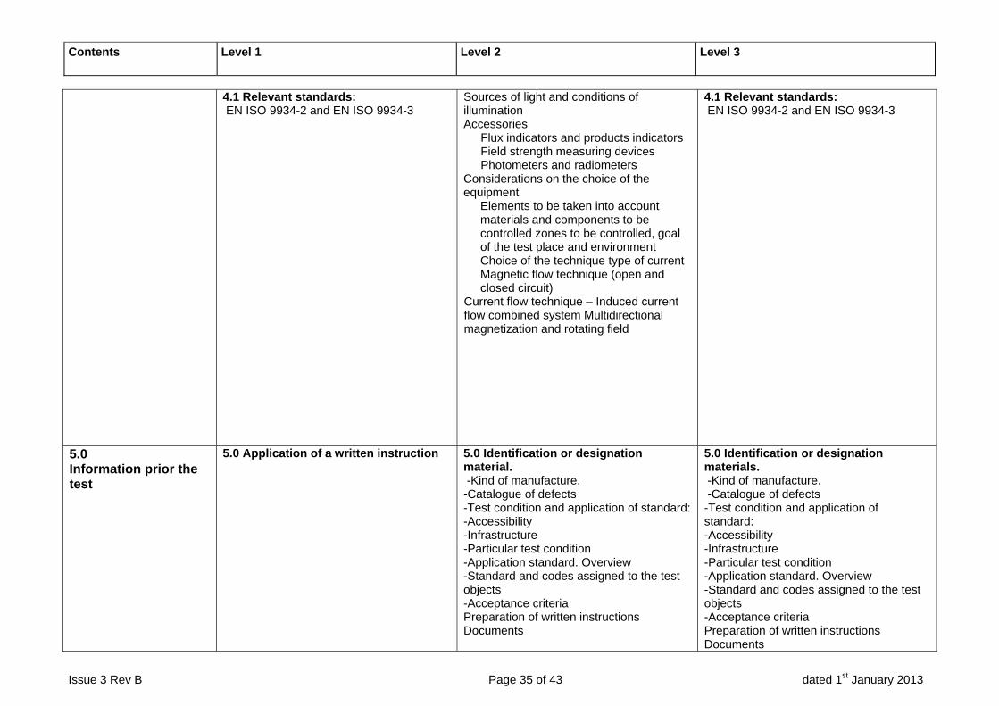
4.1 Relevant standards: EN ISO 9934-2 and EN ISO 9934-3
Sources of light and conditions of illumination Accessories
Flux indicators and products indicators Field strength measuring devices Photometers and radiometers
Considerations on the choice of the equipment
Elements to be taken into account materials and components to be controlled zones to be controlled, goal of the test place and environment Choice of the technique type of current Magnetic flow technique (open and closed circuit)
Current flow technique – Induced current flow combined system Multidirectional magnetization and rotating field
4.1 Relevant standards: EN ISO 9934-2 and EN ISO 9934-3
5.0 Information prior the test
5.0 Application of a written instruction
5.0 Identification or designation material. -Kind of manufacture. -Catalogue of defects -Test condition and application of standard: -Accessibility -Infrastructure -Particular test condition -Application standard. Overview -Standard and codes assigned to the test objects -Acceptance criteria Preparation of written instructions Documents
5.0 Identification or designation materials. -Kind of manufacture. -Catalogue of defects -Test condition and application of standard: -Accessibility -Infrastructure -Particular test condition -Application standard. Overview -Standard and codes assigned to the test objects -Acceptance criteria Preparation of written instructions Documents
Contents Level 1 Level 2 Level 3
Issue 3 Rev B Page 36 of 43 dated 1st January 2013
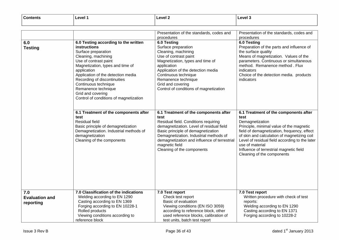
Presentation of the standards, codes and procedures
Presentation of the standards, codes and procedures
6.0 Testing
6.0 Testing according to the written instructions Surface preparation Cleaning, machining Use of contrast paint Magnetization, types and time of application Application of the detection media Recording of discontinuities Continuous technique Remanence technique Grid and covering Control of conditions of magnetization
6.0 Testing Surface preparation Cleaning, machining Use of contrast paint Magnetization, types and time of application Application of the detection media Continuous technique Remanence technique Grid and covering Control of conditions of magnetization
6.0 Testing Preparation of the parts and influence of the surface quality Means of magnetization. Values of the parameters. Continuous or simultaneous method. Remanence method . Flux indicators Choice of the detection media. products indicators
6.1 Treatment of the components after test Residual field Basic principle of demagnetization Demagnetization. Industrial methods of demagnetization Cleaning of the components
6.1 Treatment of the components after test Residual field. Conditions requiring demagnetization. Level of residual field Basic principle of demagnetization Demagnetization. Industrial methods of demagnetization and influence of terrestrial magnetic field Cleaning of the components
6.1 Treatment of the components after test Demagnetization Principle, minimal value of the magnetic field of demagnetization, frequency, effect of skin and calculation of magnetizing coil Level of residual field according to the later use of material Influence of terrestrial magnetic field Cleaning of the components
7.0 Evaluation and reporting
7.0 Classification of the indications Welding according to EN 1290 Casting according to EN 1369 Forging according to EN 10228-1 Rolled products
Viewing conditions according to reference block
7.0 Test report Check test report Basic of evaluation Viewing conditions (EN ISO 3059) according to reference block, other used reference blocks, calibration of test units, batch test report
7.0 Test report Written procedure with check of test reports: Welding according to EN 1290 Casting according to EN 1371 Forging according to 10228-2

Contents Level 1 Level 2 Level 3
Issue 3 Rev B Page 37 of 43 dated 1st January 2013
Verification the indication quality (EN ISO 3059) Report of simple welding, forging, rolled products and casting imperfections
Evaluation and verification the indication quality Report of imperfections according to EN 1290, EN 1369, EN 10228-1
Basics of evaluation, viewing conditions (EN ISO 3059) according to reference block, other used refer-ence blocks calibration of test units Evaluation verification the indication quality
8.0 Assessment
Not applicable
Assessment of discontinuities Influence of manufacture and material
Assessment of discontinuities Influence of manufacture and material
9.0 Quality aspects
9.0 Personnel qualification (according to EN ISO 9712) Equipment verification
9.0 Personnel qualification (according to EN ISO 9712) Equipment verification Written instructions Traceability of documents A review of applicable NDT application and product standards
9.0 Personnel qualification (according to EN ISO 9712) Equipment verification Format of working procedures Traceability of documents A review of applicable NDT application and product standards
10.0 Environmental and Safety conditions
10.0 Health and Safety Electric risks hazards Risks related to the products (magnetic inks) Risks related to the ultraviolet radiation Disposal of the effluents and environmental conditions (concepts) Safety data sheet
10.0 Health and Safety Electric risks hazards Risks related to the products (magnetic inks) Risks related to the ultraviolet radiation Disposal of the effluents and environmental conditions (concepts) Safety data sheet
10.0 Health and Safety Electric risks hazards Risks related to the products (magnetic inks) Risks related to the ultraviolet radiation Disposal of the effluents and environmental conditions (concepts) Harmfulness and toxicity of the products Treatment and rejection of the effluents, environmental conditions Fire hazards Risks related to the ultraviolet radiations
11.0 Developments
(Not applicable) Special installation and equipment New techniques Creative and innovative special installations
Contents Level 1 Level 2 Level 3
Issue 3 Rev B Page 38 of 43 dated 1st January 2013
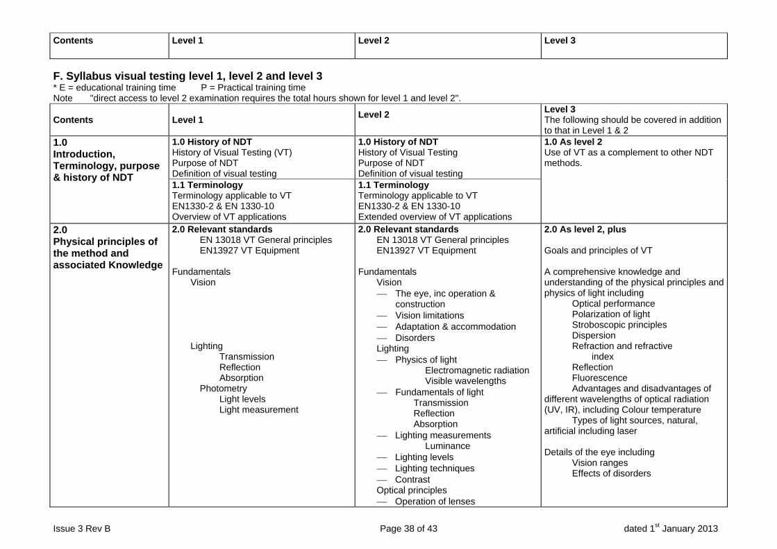
F. Syllabus visual testing level 1, level 2 and level 3 * E = educational training time P = Practical training time Note "direct access to level 2 examination requires the total hours shown for level 1 and level 2".
Contents Level 1 Level 2
Level 3 The following should be covered in addition to that in Level 1 & 2
1.0 Introduction, Terminology, purpose & history of NDT
1.0 History of NDT History of Visual Testing (VT) Purpose of NDT Definition of visual testing
1.0 History of NDT History of Visual Testing Purpose of NDT Definition of visual testing
1.0 As level 2 Use of VT as a complement to other NDT methods.
1.1 Terminology Terminology applicable to VT EN1330-2 & EN 1330-10 Overview of VT applications
1.1 Terminology Terminology applicable to VT EN1330-2 & EN 1330-10 Extended overview of VT applications
2.0 Physical principles of the method and associated Knowledge
2.0 Relevant standards EN 13018 VT General principles EN13927 VT Equipment Fundamentals Vision Lighting Transmission Reflection Absorption Photometry Light levels Light measurement
2.0 Relevant standards EN 13018 VT General principles EN13927 VT Equipment Fundamentals Vision
The eye, inc operation & construction
Vision limitations Adaptation & accommodation Disorders
Lighting Physics of light
Electromagnetic radiation Visible wavelengths
Fundamentals of light Transmission Reflection Absorption
Lighting measurements Luminance
Lighting levels Lighting techniques Contrast
Optical principles Operation of lenses
2.0 As level 2, plus Goals and principles of VT A comprehensive knowledge and understanding of the physical principles and physics of light including Optical performance Polarization of light Stroboscopic principles Dispersion Refraction and refractive index Reflection Fluorescence Advantages and disadvantages of different wavelengths of optical radiation (UV, IR), including Colour temperature Types of light sources, natural, artificial including laser Details of the eye including Vision ranges Effects of disorders
Contents Level 1 Level 2 Level 3
Issue 3 Rev B Page 39 of 43 dated 1st January 2013
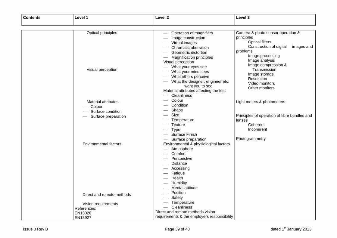
Optical principles Visual perception Material attributes
Colour Surface condition Surface preparation
Environmental factors Direct and remote methods Vision requirements References: EN13028 EN13927
Operation of magnifiers Image construction Virtual images Chromatic aberration Geometric distortion Magnification principles
Visual perception What your eyes see What your mind sees What others perceive What the designer, engineer etc.
want you to see Material attributes affecting the test
Cleanliness Colour Condition Shape Size Temperature Texture Type Surface Finish Surface preparation
Environmental & physiological factors Atmosphere Comfort Perspective Distance Accessing Fatigue Health Humidity Mental attitude Position Safety Temperature Cleanliness
Direct and remote methods vision requirements & the employers responsibility
Camera & photo sensor operation & principles Optical filters Construction of digital images and problems Image processing Image analysis Image compression & Transmission Image storage Resolution Video monitors Other monitors Light meters & photometers Principles of operation of fibre bundles and lenses Coherent Incoherent Photogrammetry
Contents Level 1 Level 2 Level 3
Issue 3 Rev B Page 40 of 43 dated 1st January 2013
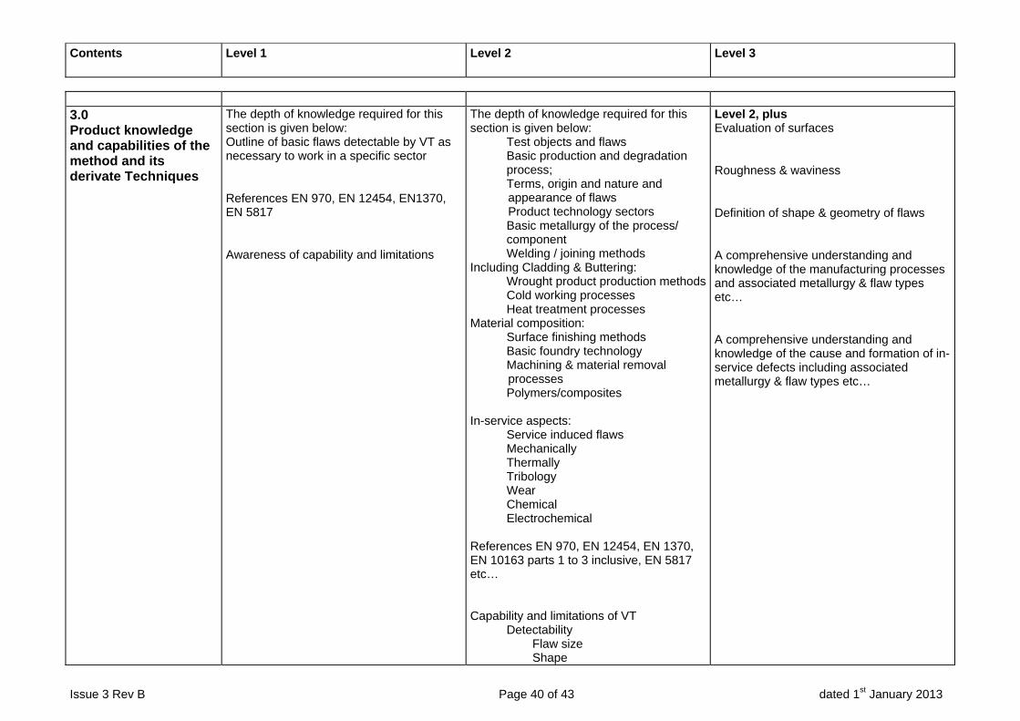
3.0 Product knowledge and capabilities of the method and its derivate Techniques
The depth of knowledge required for this section is given below: Outline of basic flaws detectable by VT as necessary to work in a specific sector
References EN 970, EN 12454, EN1370, EN 5817
Awareness of capability and limitations
The depth of knowledge required for this section is given below: Test objects and flaws Basic production and degradation process; Terms, origin and nature and
appearance of flaws Product technology sectors
Basic metallurgy of the process/ component Welding / joining methods Including Cladding & Buttering: Wrought product production methods Cold working processes Heat treatment processes Material composition: Surface finishing methods Basic foundry technology Machining & material removal
processes Polymers/composites In-service aspects: Service induced flaws Mechanically Thermally Tribology Wear Chemical Electrochemical References EN 970, EN 12454, EN 1370, EN 10163 parts 1 to 3 inclusive, EN 5817 etc… Capability and limitations of VT Detectability Flaw size Shape
Level 2, plus Evaluation of surfaces
Roughness & waviness
Definition of shape & geometry of flaws
A comprehensive understanding and knowledge of the manufacturing processes and associated metallurgy & flaw types etc…
A comprehensive understanding and knowledge of the cause and formation of in-service defects including associated metallurgy & flaw types etc…

Contents Level 1 Level 2 Level 3
Issue 3 Rev B Page 41 of 43 dated 1st January 2013
Orientation/ position Flaw types Surface condition effects Equipment limitations Lighting effects Associated techniques Gauging Comparators Measurement Thermographic imaging Replication References: ISO3057
4.0 Equipment
4.0 Introduction to equipment Mirrors Magnifiers (ref ISO 3058) Borescopes Fibrescopes Photographic & video:
Imaging cameras Light sources and special lighting Gauges, templates, scales,
special tools, etc. Automated systems Computer-enhanced systems Demonstration test piece Resolution targets Or other special equipment as necessary for the test. Why equipment must be verified References: EN 13927 ISO 3058
4.0 Introduction to, and applications of equipment Mirrors Magnifiers (ref ISO 3058) Borescopes Fibrescopes Photographic & video:
Imaging cameras Video monitors Light sources and special lighting Gauges, templates, scales, special
tools, etc. Automated systems Computer-enhanced systems Demonstration test piece Resolution targets Graticules Image recording, transfer & storage equipment:
Equipment selection & limitations Verification of equipment
Sizing of indications: Imaging systems Special optical systems
Or other special equipment as necessary for the test, such as underwater, radiation resistant, etc.
As level 2, plus the inclusion of equipment for assessment of surface conditions A good understanding of equipment performance limitations & the selection of new equipment for its suitability. Additionally, the effect this will have on the test arrangement The evaluation of equipment to fulfil a particular task Development of verification for equipment performance, including the choice/design and application of demonstration test pieces Understanding of the procedure for control, maintenance and calibration of equipment

Contents Level 1 Level 2 Level 3
Issue 3 Rev B Page 42 of 43 dated 1st January 2013
5.0 Information prior to the Test
5.0 Pre-test documentation (ref EN13018)
Test instruction Written procedure (when required)
These should specify the following aspects: Object to be tested Extent of test coverage Technique & sequence of performing test Surface condition Surface preparation The stage of manufacture or service life when testing is to be carried out The requirements of test personnel The acceptance criteria The illumination (type, level and direction) The visual testing equipment to be used The post test documentation A demonstration test piece & inspection checkpoints Requirement for recorded images References: EN13018
5.0 Pre-test documentation (ref EN13018)
Test instruction Written procedure or standard (when required) These should specify the following aspects: Object to be tested Extent of test coverage Technique & sequence of performing Test Surface condition Surface preparation The stage of manufacture or service life when testing is to be carried out The requirements of test personnel The acceptance criteria The illumination (type, level and direction) The visual testing equipment to be used The post test documentation A demonstration test piece & inspection checkpoints Requirement for recorded images Development and writing of NDT instructions for level I for a given test specimen, from standards or codes.
5.0 As level 2, plus the writing of procedures and the design of the test arrangement.
The development & application of verification techniques including the demonstration of procedures and instructions for effectiveness. A thorough knowledge of complementary
NDT methods that may be referenced in written procedures.
6.0 Testing
6.0 How to set up a test Working with demonstration test pieces and resolution targets Practical training on test equipment and performing tests on training test pieces with known flaws to provided instructions/ procedures including equipment and test parameters.
6.0 How to set up and calibrate a test Specifying & Working with demonstration test pieces and resolution targets Prepare written test instructions from standards or codes for given test pieces. Practical training on test equipment and performing tests on training test pieces with known flaws to instructions as above including equipment and test parameters.
6.0 As level 2, plus the control of procedures and instructions for their effectiveness

Contents Level 1 Level 2 Level 3
Issue 3 Rev B Page 43 of 43 dated 1st January 2013
7.0 Evaluation and Reporting
7.0 Reporting the results of tests
Reference to test standards Calibration status Reference points for location of indications Classification of indications per: instructed acceptance criteria reports and documentation reporting verification results
7.0 Level 1 detail, plus How to control and monitor a Level 1 test done with your guidance. Interpretation, evaluation & reporting of results to specifications and standards Objective/Subjective evaluation Completion of calibration forms
7.0 As level 2 plus how to develop report formats for ease of use and clarity. Organization and storage/distribution of final reports Investigation of suitable codes & product standards for each application Acting as a reference point for level 2 advice for interpretation and evaluation References: EN 13445-5 EN 12732 EN 12952 etc.
8.0 Assessment
Not Applicable Classification & assessment of observations per acceptance criteria from the codes, standards or written instructions etc. or by specific reference to a level 3 where no codes or standards exist. By comparison By measurement Automated evaluation e.g. pattern recognition Recording Reporting
Detailed knowledge of how to classify & assess observations, analyse the results and compare them to codes, standards and design specifications etc. How to develop codes, standards and design specifications etc. into clear acceptance criteria to be written into procedures and instructions Also how to find information /assistance to investigate observations not covered by codes and standards & develop acceptance criteria. The training of levels 1 & 2 for these acceptance criteria.
9.0 Quality aspects
9.0 Personnel qualification (according to EN ISO 9712) Equipment verification
9.0 Personnel qualification (according to EN ISO 9712) Equipment verification Written instructions Traceability of documents A review of applicable NDT application and product standards
9.0 Personnel qualification (according to EN ISO 9712) Equipment verification Format of working procedures Traceability of documents Other NDT qualification and certification systems A review of applicable NDT application and product standards
10.0 Development
Not applicable General information The importance of investigating current and developing technology and methods of application. Summary of latest developments


![Ndt Training - Ultrasonic Methode[1]](https://img.dokumen.tips/doc/110x75/5571f88c49795991698da7a2/ndt-training-ultrasonic-methode1.jpg)


