Embed Size (px)
Citation preview
Unit –I Basics of Computer Graphics (8 marks)
Marathwada Mitra Mandals Polytechnic, Thergaon.
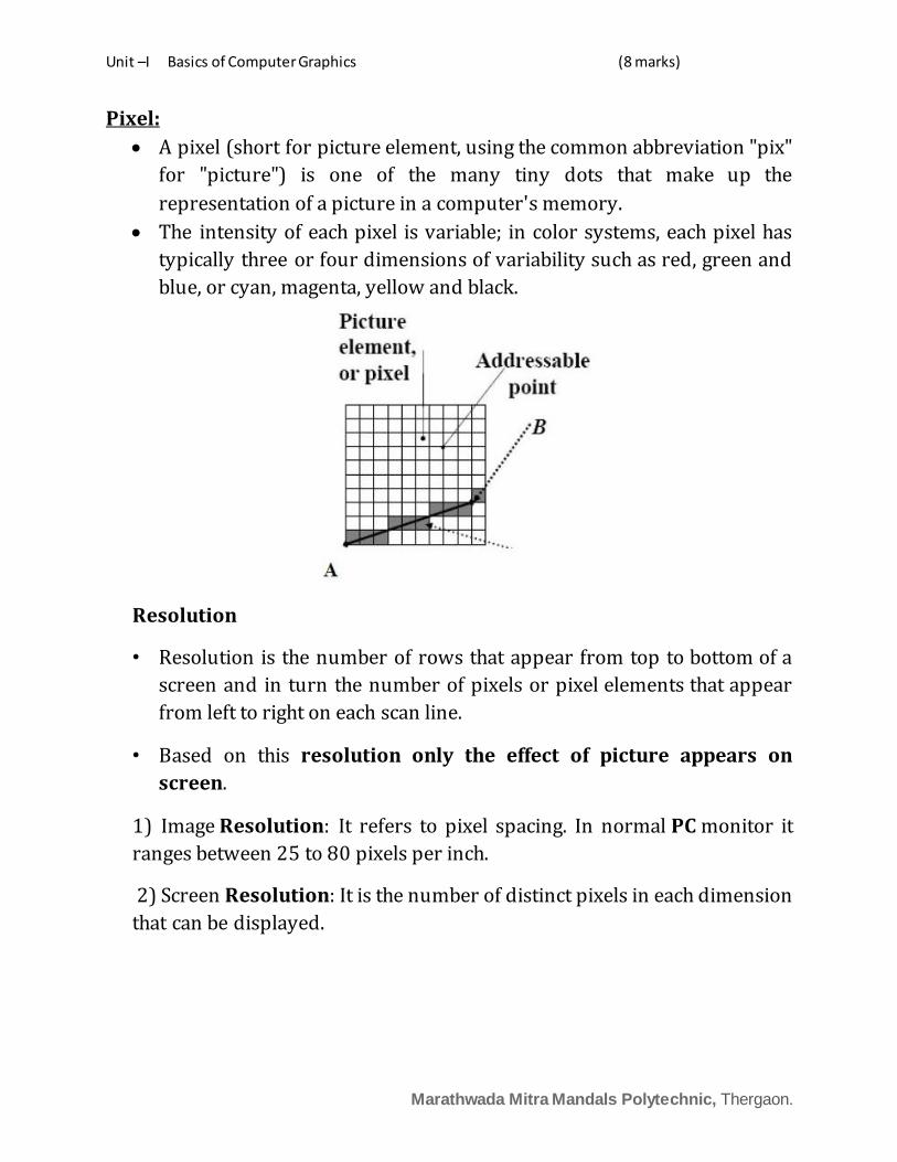
Pixel:
A pixel (short for picture element, using the common abbreviation "pix"
for "picture") is one of the many tiny dots that make up the
representation of a picture in a computer's memory.
The intensity of each pixel is variable; in color systems, each pixel has
typically three or four dimensions of variability such as red, green and
blue, or cyan, magenta, yellow and black.
Resolution
• Resolution is the number of rows that appear from top to bottom of a
screen and in turn the number of pixels or pixel elements that appear
from left to right on each scan line.
• Based on this resolution only the effect of picture appears on
screen.
1) Image Resolution: It refers to pixel spacing. In normal PC monitor it
ranges between 25 to 80 pixels per inch.
2) Screen Resolution: It is the number of distinct pixels in each dimension
that can be displayed.
Unit –I Basics of Computer Graphics (8 marks)
Marathwada Mitra Mandals Polytechnic, Thergaon.
Text mode
• Text mode is a personal computer display setting that divides the
display screen into 25 rows and 80 columns in order to display text
without images.
• In text mode, each box can contain one character. Text mode is also
known as character mode or alphanumeric mode. In character mode,
the display screen is treated as an array of blocks, each of which can
hold one ASCII character.
Graphics Mode
Graphics mode is the more sophisticated. Programs that run in
graphics mode can display an unlimited variety of shapes and fonts.
Programs that run entirely in graphics mode are called graphics-
based programs. In graphics mode, the display screen is treated as an
array of pixels. Characters and other shapes are formed by turning
on combinations of pixels.
Graphics Mode Graphics Function
The graphics-mode functions allow you to draw dots, lines, and shapes (like circles, rectangles, and ellipse etc.), add color to lines and areas, and perform many other graphics-related activities.
Setting up Graphics Mode
detectgraph() : This function checks the system and returns two integer parameters: a value representing the system's graphics driver and a value for the recommended graphics mode if an adapter is installed.
The mode value is the highest resolution possible with that adapter. Syntax: detectgraph(int *gdriver, int *gmode);
initgraph (): This library function must be executed before any other graphics mode functions can be used.
This requires the GRAPHICS.H header file. Syntax: initgraph(int *driver, int *mode, char *path);
where *driver is the graphics driver, given by an integer. *mode is the graphics mode, given by an integer.
Unit –I Basics of Computer Graphics (8 marks)
Marathwada Mitra Mandals Polytechnic, Thergaon.
*path is a string indicating where the driver is available note:The Driver is a file extention BGI.Each type of hardware requires a
different driver.A null string ("") indicates sriver is in the current directory.
Graphics Pipeline
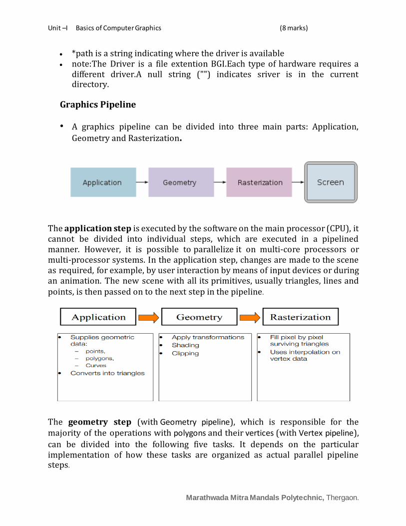
• A graphics pipeline can be divided into three main parts: Application,
Geometry and Rasterization.
The application step is executed by the software on the main processor (CPU), it cannot be divided into individual steps, which are executed in a pipelined manner. However, it is possible to parallelize it on multi-core processors or multi-processor systems. In the application step, changes are made to the scene as required, for example, by user interaction by means of input devices or during an animation. The new scene with all its primitives, usually triangles, lines and points, is then passed on to the next step in the pipeline.
The geometry step (with Geometry pipeline), which is responsible for the majority of the operations with polygons and their vertices (with Vertex pipeline),
can be divided into the following five tasks. It depends on the particular implementation of how these tasks are organized as actual parallel pipeline steps.

Unit –I Basics of Computer Graphics (8 marks)
Marathwada Mitra Mandals Polytechnic, Thergaon.
The Rasterization step is the task of taking an image described in a vector graphics format (shapes) and converting it into a raster image (pixels or dots) for output on a video display or printer, or for storage in a bitmap file format. It refers to both rasterization of models and 2D rendering primitives such as polygons, line segments, etc.
Bitmap based Graphics
Bitmap (or raster) images are stored as a series of tiny dots called pixels. Each pixel is actually a very small square that is assigned a color, and then arranged in a pattern to form the image. When you zoom in on a bitmap image you can see the individual pixels that make up that image. The three most popular image formats used on the Web (PNG, JPEG, and GIF) are bitmap formats. The bitmap format is excellent for creating backgrounds and overlay elements.
Vector based graphics
Vector images are not based on pixel patterns, but instead use mathematical formulas to draw lines and curves that can be combined to create an image from geometric objects such as circles and polygons. All major browsers support the SVG (Scalable Vector Graphics) format. Vector graphics are more flexible than bit-maps because they can be easily re-sized. Vector-based graphics can be very useful when creating large illustrations, as these graphics are resolution independent.
Applications of Computer Graphics
• Computer graphics user interfaces (GUIs) − A graphic, mouse-oriented paradigm which allows the user to interact with a computer.
• Business presentation graphics − "A picture is worth a thousand words".

Unit –I Basics of Computer Graphics (8 marks)
Marathwada Mitra Mandals Polytechnic, Thergaon.
• Cartography − Drawing maps. • Weather Maps − Real-time mapping, symbolic representations. • Satellite Imaging − Geodesic images. • Photo Enhancement − Sharpening blurred photos. • Medical imaging − MRIs, CAT scans, etc. - Non-invasive internal
examination. • Engineering drawings − mechanical, electrical, civil, etc. - Replacing the
blueprints of the past. • Architecture − Construction plans, exterior sketches - replacing the
blueprints and hand drawings of the past. • Art − Computers provide a new medium for artists. • Entertainment − Movies and games. • Simulation and modeling − Replacing physical modeling and enactments
RASTER-SCAN DISPLAYS
In a raster scan system, the electron beam is swept across the screen,
one row at a time from top to bottom. As the electron beam moves
across each row, the beam intensity is turned on and off to create a
pattern of illuminated spots.
Picture definition is stored in memory area called the Refresh
Buffer or Frame Buffer. This memory area holds the set of intensity
values for all the screen points. Stored intensity values are then
retrieved from the refresh buffer and “painted” on the screen one row
(scan line) at a time as shown in the following illustration.

Unit –I Basics of Computer Graphics (8 marks)
Marathwada Mitra Mandals Polytechnic, Thergaon.
Each screen point is referred to as a pixel (picture element) or pel. At
the end of each scan line, the electron beam returns to the left side of
the screen to begin displaying the next scan line.
Random-Scan Display
In this technique, the electron beam is directed only to the part of the
screen where the picture is to be drawn rather than scanning from left
to right and top to bottom as in raster scan. It is also called vector
display, stroke-writing display, or calligraphic display.
Picture definition is stored as a set of line-drawing commands in an
area of memory referred to as the refresh display file.
To display a specified picture, the system cycles through the set of
commands in the display file, drawing each component line in turn.

Unit –I Basics of Computer Graphics (8 marks)
Marathwada Mitra Mandals Polytechnic, Thergaon.
After all the line-drawing commands are processed, the system cycles
back to the first line command in the list.
Random-scan displays are designed to draw all the component lines of
a picture 30 to 60 times each second.
Flat Panel Display
The term flat–panel displays refers to a class of video devices that have
reduced volume, weight, and power requirements compared to a CRT.
A significant feature of flat-panel displayed is that they are thinner than
CRTs, and we can hang them on walls or wear them on our wrists.
Flat-panel displays into two categories: emissive displays and
nonemissive displays.
The emissive displays are devices that displays, and light-emitting
diodes are examples of emissive displays.
Nonemissive displays use optical effects to convert sunlight or light
from some other source into graphics patterns.
Unit –I Basics of Computer Graphics (8 marks)
Marathwada Mitra Mandals Polytechnic, Thergaon.
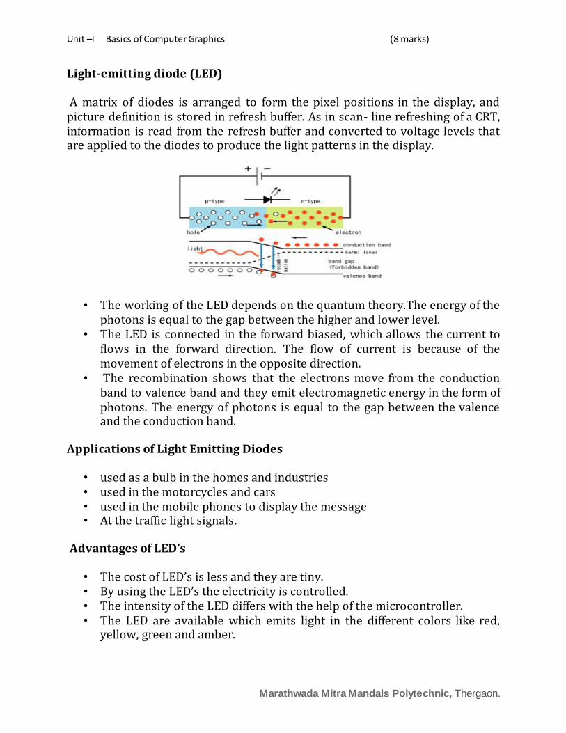
Light-emitting diode (LED)
A matrix of diodes is arranged to form the pixel positions in the display, and picture definition is stored in refresh buffer. As in scan- line refreshing of a CRT, information is read from the refresh buffer and converted to voltage levels that are applied to the diodes to produce the light patterns in the display.
• The working of the LED depends on the quantum theory.The energy of the photons is equal to the gap between the higher and lower level.
• The LED is connected in the forward biased, which allows the current to flows in the forward direction. The flow of current is because of the movement of electrons in the opposite direction.
• The recombination shows that the electrons move from the conduction band to valence band and they emit electromagnetic energy in the form of photons. The energy of photons is equal to the gap between the valence and the conduction band.
Applications of Light Emitting Diodes
• used as a bulb in the homes and industries • used in the motorcycles and cars • used in the mobile phones to display the message • At the traffic light signals.
Advantages of LED’s
• The cost of LED’s is less and they are tiny. • By using the LED’s the electricity is controlled. • The intensity of the LED differs with the help of the microcontroller. • The LED are available which emits light in the different colors like red,
yellow, green and amber.

Unit –I Basics of Computer Graphics (8 marks)
Marathwada Mitra Mandals Polytechnic, Thergaon.
Disadvantages of LED
• The LED consumes more power as compared to LCD, and their cost is high. Also, it is not used for making the large display.
Liquid-crystal display (LCD)
• It is combination of two states of matter, the solid and the liquid. • LCD uses a liquid crystal to produce a visible image. • LCD commonly used in systems, such as calculators and portable, laptop
computers. • The basic structure of LCD should be controlled by changing the applied
current. • We must use a polarized light. • Liquid crystal should able be to control both of the operation to transmit
or can also able to change the polarized light.
Advantages of an LCD’s:
• LCD’s consumes less amount of power compared to CRT and LED • LCDs are of low cost • Provides excellent contrast • LCD’s are thinner and lighter when compared to cathode ray tube and LED
Disadvantages of an LCD’s:
• Require additional light sources • Range of temperature is limited for operation • Low reliability • Speed is very low
Applications of Liquid Crystal Display
Unit –I Basics of Computer Graphics (8 marks)
Marathwada Mitra Mandals Polytechnic, Thergaon.
• Liquid crystal thermometer ,Optical imaging, Used in the medical applications
Plasma Display Panel
• A plasma display is a type of flat panel display . • Plasma displays are also known as gas-plasma displays. • A plasma display panel (PDP) is a type of flat panel display common to
large TV displays 30 inches (76 cm) or larger. • They are called "plasma" displays because they use small cells
containing electrically charged ionized gases, which are plasmas. • Plasma displays are thinner than cathode ray tube ( CRT ) displays and
brighter than liquid crystal displays ( LCD).
Touch Screen
• A touch screen is a computer display screen that is also an input device. The screens are sensitive to pressure; a user interacts with the computer by touching pictures or words on the screen.
• There are three types of touch screen technology:
Resistive Surface wave Capacitive
Output primitives
• The Primitives are the simple geometric functions that are used to generate various Computer Graphics required by the User. Some most basic Output primitives are point-position (pixel), and a straight line.
• Line, polygon , marker , text.
Line Attributes
• A straight-line segment can be displayed with three basic attributes: color,
width, and style. Additionally, lines may be generated with other effects,
such as pen and brush strokes.
• To set line type attributes in a PHICS application program, a user invokes the
function :setLinetype (It)

Unit –I Basics of Computer Graphics (8 marks)
Marathwada Mitra Mandals Polytechnic, Thergaon.
where parameter It is assigned a positive integer value of 1,2,3, or 4 to
generate lines that are, respectively, solid, dashed, dotted, or dash-dotted.
Marker Attributes
A marker symbol display single character in a different color and in different sizes.
We select marker type using the function. setMarkerType (mt)
Where marker type parameter mt set to an integer code. Typical codes for marker type are the integers 1 through 5, specifying,
respectively, a dot (.), a vertical cross (+), an asterisk (*), a circle (o), and a diagonal cross (x). Displayed marker types centered on the marker coordinates.
Text Attributes
The attributes that can be assigned to text are common knowledge nowadays: Font (e.g. Courier, Arial, Times, Broadway, …), style (normal, bold, italic, underlined, …), size, text direction, color, alignment (left, right, centered, justified) and so on.
Attributes of Polygons
A set of line segments joined end to end. Attributes: Fill color, Thickness, Fill pattern

Unit –I Basics of Computer Graphics (8 marks)
Marathwada Mitra Mandals Polytechnic, Thergaon.
Graphics Functions
Standard graphics formats allow images to be moved from machine to machine, while standard graphics languages let graphics programs be moved from machine to machine. For example, GKS, PHIGS and OpenGL are major graphics languages . GDI and DirectX are the graphics languages in Windows.
Putpixel function is to draw the pixel on the screen. Pixel is small dot on the screen.
Syntax:-putpixel(x co-orinate, y co-ordinate,COLOR);
Example: – putpixel(100,100,BLUE);
Rectangle function is used to draw the rectangle on the screen. X1,y1 are the lower left co-ordinates of the rectangle and the x2,y2 are the upper right co-ordinates of the rectangle.
Syntax:– rectangle(x1,,y1,x2,y2);
Example:– rectangle(100,100,200,200);
Line function is used to draw the line on the screen.
Syntax: line(x1,y1,x2,y2);
Example:-line(100,100,200,100);
Circle function is used to draw the circle on the screen
Syntax:– circle(x,y,radius);
Example:-circle(100,100,50);
ellipse function is used to draw the ellipse on the screen.
Syntax:-ellipse(x, y, starting angle, ending angle, xradius, yradius);
Example:-ellipse(100,100,90,200,20,20);

Unit –I Basics of Computer Graphics (8 marks)
Marathwada Mitra Mandals Polytechnic, Thergaon.
Virtual reality
• Virtual reality (VR) means experiencing things through our
computers that don't really exist.
• A believable, interactive 3D computer-created world that you can
explore so you feel you really are there, both mentally and physically.
• Virtual reality essentially to make world Believable, Interactive, Computer-generated, Explorable and Immersive(to be both believable and interactive).
Types of Virtual reality (VR) System
1. Windows on World(WoW)
– Also called Desktop VR.
– Using a conventional computer monitor to display the 3D virtual
world.
2. Immersive VR
– Completely immerse the user's personal viewpoint inside the
virtual 3D world.
– The user has no visual contact with the physical word.
– Often equipped with a Head Mounted Display (HMD).
3. Telepresence
– A variation of visualizing complete computer generated worlds.
4. Mixed Reality(Augmented Reality)
- The seamless merging of real space and virtual space
Unit –I Basics of Computer Graphics (8 marks)
Marathwada Mitra Mandals Polytechnic, Thergaon.
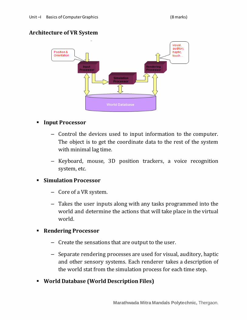
Architecture of VR System
Input Processor
– Control the devices used to input information to the computer.
The object is to get the coordinate data to the rest of the system
with minimal lag time.
– Keyboard, mouse, 3D position trackers, a voice recognition
system, etc.
Simulation Processor
– Core of a VR system.
– Takes the user inputs along with any tasks programmed into the
world and determine the actions that will take place in the virtual
world.
Rendering Processor
– Create the sensations that are output to the user.
– Separate rendering processes are used for visual, auditory, haptic
and other sensory systems. Each renderer takes a description of
the world stat from the simulation process for each time step.
World Database (World Description Files)

Unit –I Basics of Computer Graphics (8 marks)
Marathwada Mitra Mandals Polytechnic, Thergaon.
– Store the objects that inhabit the world, scripts that describe
actions of those objects.
What equipment do we need for virtual reality?
Head-mounted displays (HMDs) Data gloves Binocular Omni-Orientation Monitor (BOOM) Cave Automatic Virtual Environment (CAVE)
Applications
Entertainment Medicine Manufacturing Education & Training
Augmented Reality (AR)
Augmented reality combines real and computer-based scenes and
images to deliver a unified but enhanced view of the world .
• There are three components needed in order to make an augmented-
reality system work:
– Head-mounted display
– Tracking system
– Mobile computing power
• Future of Augmented Reality
• Military:
– The Office of Naval Research has sponsored AR research
– AR system could provide troops with vital information about their
surroundings.
• Medical:
Unit –I Basics of Computer Graphics (8 marks)
Marathwada Mitra Mandals Polytechnic, Thergaon.
– Superimpose an image from an MRI onto a patient’s body.
– This might allow surgeons to pinpoint a tumor to remove.
• Education:
– Used in labs where students can learn more about the
experiments they are participating in.
• Gaming:
– ARQuake is an AR version of the popular game Quake.
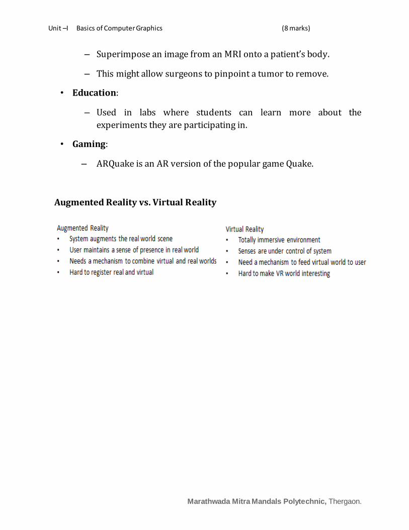
Augmented Reality vs. Virtual Reality