Embed Size (px)
Citation preview

Progress In Electromagnetics Research M, Vol. 66, 87–98, 2018
Pattern Synthesis for the Cylindrical Polarimetric Phased ArrayRadar (CPPAR)
Mohammad-Hossein Golbon-Haghighi1, *, Hadi Saeidi-Manesh1,Guifu Zhang1, 2, and Yan Zhang1
Abstract—A new optimization algorithm for the Cylindrical Polarimetric Phased Array Radar(CPPAR) antenna pattern synthesis is presented to achieve multi-mission requirements. To allowaccurate weather measurements, the CPPAR antenna needs to have matched co-polarization (H andV ) patterns, low sidelobe levels and high cross-polarization purity. To achieve these goals, first, a high-performance dual-polarized hybrid-fed microstrip patch antenna is designed, and its embedded radiationpattern is extracted. Then, a pattern synthesis using a new optimization method is presented to findthe optimal weights for each radiating element and each polarization. The modified particle swarmoptimization (MPSO) with new features is used to optimize the current distribution of the CPPAR.The adaptive beamforming algorithm also has the capability to mitigate interference by steering nullsof the radiation pattern in the desired direction without affecting the main beam. The performanceimprovement is demonstrated through the simulation results.
1. INTRODUCTION
The Multifunction Phased Array Radar (MPAR) is planned to integrate four radar networks in theUnited States. Replacing the (1) National Weather Surveillance Radar (WSR-88D or NEXRAD),(2) Terminal Doppler Weather Radar (TDWR), (3) Airport Surveillance Radar (ASR), and (4) AirRoute Surveillance Radar (ARSR) with a single radar network would be cost-effective, beneficial, andwill enable data sharing between radars [1–5]. Currently, the national weather surveillance radar hasbeen upgraded with dual-polarization capability, and it is capable of transmitting and receiving bothhorizontally and vertically polarized waves simultaneously. The dual-polarization radar will improveweather measurements and classify hydrometeor types better than single polarized weather radars.
Compared to the traditional mechanically scanned antennas, which are currently used for weathermeasurements, phased array antennas offer faster data update and higher beam agility [6]. However, ina Planar Polarimetric Phased Array Antenna (PPPAR), the antenna radiation characteristics dependon the beam pointing angle, which results in a high level of cross-polarization in the off-principle planescanning angles.
A cylindrical polarimetric phased array radar (CPPAR) has the advantages of azimuth scan-invariant pattern and polarization purity and has been proposed to overcome the deficiencies encounteredwith (PPPAR) [7]. However, the analysis and synthesis of the CPPAR antenna radiation pattern differfrom that of PPPAR. The pattern synthesis for CPPAR is complicated because the element positionsare not in one plane, and the array parameters are nonlinearly related to the element radiation pattern.Therefore, evolutionary optimization algorithms, including genetic algorithm (GA) [8, 9], particle swarm
Received 10 January 2018, Accepted 18 March 2018, Scheduled 26 March 2018* Corresponding author: Mohammad-Hossein Golbon-Haghighi ([email protected]).1 School of Electrical & Computer Engineering, Advanced Radar Research Center (ARRC), The University of Oklahoma, USA.2 School of Meteorology, The University of Oklahoma, USA.
88 Golbon-Haghighi et al.
optimization (PSO) [10] and invasive weed optimization (IWO) [11–13], have been proposed to solvethis optimization problem.
The first step in carrying out weather measurements is to generate a set of transmit beamformingweights for each embedded element pattern. However, finding these beamforming weights and patternsynthesis of nonplanar or cylindrical arrays is more complicated than for planar arrays. Severaloptimization algorithms for pattern synthesis have been recently proposed with smooth (parameterized)amplitude distributions, such as Bernstein polynomial [10, 13]. These algorithms use a predefinedsmooth amplitude distribution with fewer optimization variables and fewer degrees of freedom. Althoughthese smooth amplitude distributions have a limited number of variables to be optimized (which reducesthe optimization time and complexity), their optimization does not always converge for multi-objectiveoptimizations. This is because the feasible sets of the optimization problem are bounded by reducingthe number of optimization variables. Also, the optimization algorithms with smooth amplitudedistributions cannot match the H and V co-polarization patterns, because the radiation patterns andembedded element patterns are not symmetric due to the mutual coupling effects. Furthermore, thebeamforming optimization for null steering cannot be converged with the optimization methods basedon the smooth amplitude distributions, because the radiation patterns and amplitude distributions arenot symmetrical.
In this paper, an optimization algorithm for pattern synthesis is developed to efficiently optimize thebeamforming weights of multi-objective optimization problem for the CPPAR. The beamforming weightsare optimized to achieve the desired sidelobe levels, beam-width and matched horizontal and verticalco-polarization patterns. Also, an adaptive null steering feature is considered as another objectivefunction for the optimization problem to reduce the effect of interference and ground clutter. Ournovel optimization method is based on the particle swarm optimization (PSO) and is modified withan iterative particle replacing feature to improve computational efficiency and increase the convergencerate for our multi-objective optimization problem. For accurate weather measurements, it necessary tohave low cross-polarization and high isolation antenna. A high-performance hybrid-fed dual-polarizedmicrostrip patch antenna is also designed, and its embedded element pattern is used for cylindricalarray pattern synthesis.
This paper is organized as follows: Section 2 presents the designed of single element. In Section 3,the formulation of the CPPAR antenna pattern is presented. In Section 4, the modified PSO algorithm isdescribed. The optimization results along with the efficiency and specific features of this new algorithmare shown in Section 5. Conclusions are drawn in Section 6.
2. SINGLE ELEMENT DESIGN
In the presented hybrid feed design shown in Figure 1, horizontal polarization is excited by a balancedfeed method which consists of a pair of 180◦ out of phase probes and a transmission line that distributespower from excitation point to the probes. The phase shift between two probes is provided by lengthdifference of two arms of the horizontal polarization transmission line. Vertical polarization is excited
Figure 1. The geometry of the designed hybrid-fed microstrip patch antenna l1 = l2 = 55 mm.

Progress In Electromagnetics Research M, Vol. 66, 2018 89
through an H-shaped slot which is placed in the center of the ground plane. The H-shaped slot is fedby a transmission line laid below the ground plane. Also, since the bandwidth of the microstrip patchantenna is limited, a parasitic square patch with a smaller dimension is placed on top of the excitedradiating square patch. In this design, the transmission lines are laid on a top layer of the first substratewhich is a 1.574mm thick Rogers 5880. The ground plane is etched and on the bottom layer of the firstsubstrate. The excited radiation patch and parasitic patch are laid on the bottom side of the secondand third substrates, which are 3.175 mm thick Rogers 5880.
The simulated S-parameter of the designed single element is shown in Figure 2. As shown in Figure 2the reflection coefficient of horizontal and vertical polarizations are below −13 dB, and isolation betweenhorizontal and vertical ports is more than 52 dB. For array radiation pattern synthesis, the embedded
Figure 2. Simulated reflection coefficient and isolation of horizontal and vertical ports.
(c) (d)
(a) (b)
Figure 3. Embedded co and cross-polarization radiation pattern of the designed single element.

90 Golbon-Haghighi et al.
element pattern of the designed element is used. The advantage of using embedded element patternis that the coupling between elements will be included in the element radiation pattern and the arrayradiation pattern will be more accurate and closer to full-wave simulations than using an isolated elementpattern for calculating the array radiation pattern. Since the embedded element radiation pattern of thelarge cylindrical array antenna is similar to the embedded element radiation pattern of the planar arrayantenna, the embedded element pattern is extracted from the simulation of 5× 5-element planar arrayantenna while the center element was excited and all other elements were terminated. The embeddedelement pattern of the designed element is shown in Figure 3.
3. PATTERNS OF CYLINDRICAL ARRAYS
The analysis and synthesis of nonplanar arrays are more complicated than the analysis and synthesis ofplanar arrays because the element positions are not in one plane, and the effective element spacings arenot always equal. In cylindrical array antennas, the array factor and element patterns are not separable,and the array factor is not simple as it is for planar arrays. A cylindrical array has the advantage ofsymmetry in azimuth, making it a natural fit for applications with a full 360◦ coverage. The CPPARbeam and polarization characteristics do not change when a commutation scan is performed. A CPPARschematic is shown in Figure 4.
(a) (b)
Figure 4. Cylindrical polarimetric phased array radar; (a) schematic; (b) CPPAR.
The radiation pattern for CPPAR with radius of “r” and N elements located on a circumferenceof a cylinder at (ϕn = n∆ϕ, Zm) can be simply calculated as [14, 15].
E(θ, ϕ) =M∑
m=1
N∑
n=1
w(n,m)Fn,m(θ, ϕ)ejk(r sin θ cos(ϕ−n∆ϕ))+zm cos(θ) (1)
where N and M are the numbers of elements in H and E-planes; w(n,m) is the amplitude excitationof the nmth element; Fn,m(θ, ϕ) are the active element patterns; ϕn, zm are the location of nmthelement on the cylindrical coordinate system. Also, the element patterns of CPPAR are dependent onthe element location and due to symmetry, it can be written as:
Fn,m(θ, ϕ) = f(θ, ϕ− n∆ϕ) (2)The amplitude excitation w(n,m) contains the amplitude and phase required for array radiation
pattern synthesis. For in-phase collimated beam at the angle (θ0, ϕ0), we have:
w(n,m)Fn,m = |w(n, m)Fn,m(θ, ϕ)|e−jkr sin θ0 cos(ϕ0−n∆ϕ) (3)

Progress In Electromagnetics Research M, Vol. 66, 2018 91
It should be noted that the CPPAR array can be focused on the elevation angle that is notnecessarily broadsided or in the plane of the array (θ0 = π/2). Therefore, the array pattern for thecylindrical array in (θ0, ϕ0) direction would be:
E(θ, ϕ) =M∑
m=1
N∑
n=1
w(n,m)Fn,m(θ, ϕ)ejk((r sin θ cos(ϕ−n∆ϕ))+zm cos(θ))−(r sin θ0 cos(ϕ0−n∆ϕ))+zm cos(θ0)) (4)
4. MODIFIED PARTICLE SWARM OPTIMIZATION
In this section, the particle swarm optimization (PSO) is modified and applied to the CPPAR antennato obtain the radiation pattern with the desired sidelobe levels (SLL). Particle swarm optimizationsimulates the behaviors of bird flocking [16–18]. In this algorithm, a group of birds is randomly searchingfor food in the specific area. There is only one piece of food in the area being searched [10, 19]. Althoughall the birds do not know where the food is, they know their distance to the food, in each step. In ourcase, one set of beamforming weight w in Eq. (4) represents a particle for the optimization problem.The distance of the array radiation pattern to desired radiation pattern (i.e., mask) for each w is definedas the distance of the particle to the food or the fitness value. Thus, the best strategy to find the foodor optimal value is to follow the bird which is nearest to the food. PSO is learning from the scenarioand updating particles to solve the optimization problem. In this algorithm, every single solution isconsidered as a particle in the solution space. All the particles have fitness values which are evaluated bythe optimal value and have velocities which direct the flying of the particles to the food. The particlesfollow the current optimum particle (or local best) and fly through the problem space to find the globaloptimal value (or global best). Consider 2N variables as the phase and amplitude of N element patternsfor the optimization. Each particle is assigned a random position in the 2N -dimensional problem spaceand represents one set of beamforming weights. Therefore, each particle’s position is corresponding toa candidate solution of the optimization problem, and these particle positions are scored to calculate acost based on how well each particle solves the problem. By using a simple update rule, these particlesthen fly to new positions in the problem space, which are then mapped to the problem space and scoredin new positions.
In each step, each particle knows the best position that it has ever found, named as the local best.Each particle also knows the best position found by any other particles, named as the global best.By proceeding optimization, particles are pulled toward these known solutions with linear spring-likeattraction forces [10]. In general, PSO starts by initializing a group of particles (here 40), with randompositions. The random values are between 0 and 1. In some cases, the initial points can be defined asdeterministic distributions such as Taylor or Chebyshev distributions. The object of the optimizationproblem is to obtain sidelobe levels less than a tapered mask and holding the 3-dB beamwidth to bearound 2◦ and matched copolar patterns. Then, all these particles are scored to find the global bestparticle.
Finally, by using the following stochastic velocity update rule, the particles are flown through theproblem hyperspace for a specified number of iterations.
νk+1 = wνk + φ1rand(plocal best
k − pk
)+ φ2rand
(pglobal best
k − pk
)(5)
where pk is the position of the kth particle, plocal bestk the best position ever found by pk, pglobal best
kthe best position of any particle, vk the velocity of the kth particle, w the inertia or momentum, andφ1 and φ2 are the self-knowledge and group knowledge weights and also known as correction factors.Inertia is proportional to the old velocity and is the tendency of the particle to continue in the samedirection it has been traveling. It is possible to select this multiplier as a random value or decreasingfunction to encourage local searching at the end of the optimization process or randomly vary duringthe optimization [10]. In our case, w is assumed to be a constant value: w = 0.2.
In each iteration, the second term of the velocity (i.e., φ1rand(plocal bestk − pk)) is updating like a
linear attraction toward the best position ever found by a particle (local best) and scaled by a constantvalue and a random number. The third term of the velocity (i.e., φ2rand(pglobal best
k − pk)) is updatingthe equation as a linear attraction toward the best position found by any particle (global best) and

92 Golbon-Haghighi et al.
scaled by a constant and a random number between zero and one. For this study, the correction factorsare assumed to be: φ1 = φ2 = 2. It should be noted that a high value of φ1, φ2 can cause the particles toconverge quickly on a solution, but cannot cover enough of the solution space. If the correction factorsare too low, the swarm will lose consistency, and it will be difficult to converge on a solution space.Finally, the new position of the particle is calculated as:
pk+1 = pk + νk (6)It should be noticed that the beamforming weights should be optimized to achieve the desired
sidelobe levels, 2◦ beamwidth, matched horizontal and vertical co-polarization patterns and null steering.Therefore, for this multi-objective optimization, some of the particles have never converged to theoptimal value, as discussed in the next section. Therefore, the convergence rate can be improvedby replacing these particles with new particles. Consequently, PSO is modified with a new feature toeliminate the particles with lower fitness values and replaced them with new particles, every m iterations.The new particles are spread over the solution space, as shown in Figure 5. This feature can improvethe optimization performance, especially for multi-objective optimization problem.
Figure 5. Flowchart of the optimization algorithm.
5. OPTIMIZATION RESULTS
For the optimization problem, multi-objective functions have been considered [20–22]. The modifiedPSO algorithm is designed to match the main beams and keep the beamwidth around 2◦ whileminimizing the sidelobe levels (SLL). It is important to match the main beams because the mismatchcould result in inaccurate weather sensing. Coupling effect in the element pattern is the reason forobtaining different patterns for horizontal- and vertical-polarized beams. Therefore, in each m iterations,

Progress In Electromagnetics Research M, Vol. 66, 2018 93
the particles with the beamwidth, far from 2◦, will be replaced by new particles. New particles arereplaced over the solution space, near the global best. Therefore, new particles are distributed inrandom positions with mean equal to the global best and varying standard deviations.
Also, the optimization algorithm has been designed to match the main beam of H and Vpolarizations and also to keep all pattern peaks at the same levels compared to the mask, in orderto smooth out the amplitude distribution.
Minimizew
: SLLH,V
Subject to BWH,V = 2MBH,V ≈ 0
(7)
where w stands for the beamforming weights, SLLH,V the maximum SLLs for H and V polarizationscompared to the mask, BWH,V the 3-dB beamwidths of radiation patterns for H and V polarizations,and MBH,V the difference between main beam levels for H and V polarizations that should be matchedduring the optimization, as shown in Figure 6. For simplicity, Eq. (7) can be rewritten based on the
-20 -15 -10 -5 0 5 10 15 20
Azimuth Angle , (degree)
-33
-30
-27
-24
-21
-18
-15
-12
-9
-6
-3
0
No
rma
lize
d G
ain
(d
B)
MBH,V
SLLV
SLLH
BWH
BWV
Figure 6. Multi-objective optimization.
(a) (b)
Figure 7. Embedded element pattern in (a) horizontal plane and (b) vertical plane.

94 Golbon-Haghighi et al.
Lagrangian method:
Minimizew
: SLLH,V + λ1 (|BWH,V − 2|) + λ2(|MBH,V |) (8)
where λ1 and λ2 are the normalized coefficient for the optimization problem.Figure 7, shows the embedded element pattern for H and V polarizations. The optimized radiation
patterns at frequency 2.8 GHz are shown in Figure 8, in the horizontal plane for H and V polarizations.The beamforming weights are optimized to achieve 2◦ beamwidth with matched H and V polarizationswith respect to the pre-defined mask. A 90◦ sector of cylinder surface needs to populate with 70 columnsaround the cylinder and 53 elements in each vertical column to achieve all optimization goals, based onthe optimization results. Also, the element spacing in the horizontal plane is chosen by the optimizationprogram to be 0.58λ. Having such a spacing between elements, a CPPAR design is achieved with aheight of 3.23 m and a radius of R = 2.72m.
The mask is defined to increase from −27 dB to −34 dB at 135◦. Figure 9 shows the optimizedradiation pattern for H polarization in H-plane compared to Taylor distribution (4, −30) with thesame beamwidth. It can be seen from this figure that our modified PSO algorithm has around 4 dBgain improvement in SLL compared to Taylor distribution, for the same beamwidth and matched co-
-15 -10 -5 0 5 10 15
Azimuth Angle , (degree)
-50
-45
-40
-35
-30
-25
-20
-15
-10
-5
0
No
rmalized
Gain
(d
B)
Mask
H
V
-100 -50 0 50 100
Azimuth Angle , (degree)
-100
-90
-80
-70
-60
-50
-40
-30
-20
-10
0
No
rmalized
Gain
(d
B)
Mask
H
V
H Cross
V Cross
(a) (b)
Figure 8. Optimized radiation pattern in horizontal plane.
-135 75 -15 15 75 135
Azimuth Angle , (degree)
-70
-60
-50
-40
-30
-20
-10
0
No
rma
lize
d G
ain
(d
B)
HTaylor dist.Mask
-20 -15 -10 -5 0 5 10 15 20
Azimuth Angle , (degree)
-60
-50
-40
-30
-20
-10
0
No
rma
lize
d G
ain
(d
B)
HTaylor dist.Mask
120 125 130 135
Azimuth Angle , (degree)
-44
-42
-40
-38
-36
-34
-32
-30
-28
No
rma
lize
d G
ain
(d
B)
HTaylor dist.Mask
(a) (b) (c)
Figure 9. Optimized radiation pattern in horizontal plane compare to Taylor distribution.

Progress In Electromagnetics Research M, Vol. 66, 2018 95
polar patterns. It should be noted that the beamwidth could be reduced at the cost of increasing thesidelobe levels. However, the goal of the optimization is to achieve relatively low SLL and 2-degreebeamwidth while having the matched main beams for H and V polarizations.
Achieving both lower SLLs and reducing the beamwidth can be obtained by increasing the antennasaperture, which can cause grating lobes to appear. Therefore, we can decrease the beamwidth by eitherincreasing the spacing of elements or increasing the number of elements. Therefore, the optimizationproblem is designed to compromise between the spacing, SLL, and beamwidth, while co-polar patternsare matched. The current distribution of the radiation pattern in the horizontal plane may not besymmetrical because the embedded element patterns are not symmetrical since the patch on each columnis not designed to be in the middle of the antenna column. Furthermore, the current distribution isachieved using an evolutionary optimization algorithm which does not provide a unique solution to theoptimization problem [11].
Also, the PSO algorithm needs to optimize all 70 elements separately. It is clear that getting allof the sidelobe levels below a certain level, holding the beamwidth around 2◦ and matching the mainbeams for H and V polarizations by using the optimization algorithm results in an asymmetrical current
0 20 40 60 80 100 120 140 160 180
Zenith Angle , (degree)
-90
-80
-70
-60
-50
-40
-30
-20
-10
0
No
rma
lize
d G
ain
(d
B)
V
V cross
H
H cross
mask
Figure 10. Optimized radiation pattern in vertical plane for H and V polarizations.
(a) (b)
Figure 11. Optimized 2D co-polar radiation pattern for H polarization.
96 Golbon-Haghighi et al.
distribution. This will not affect the practical implantation of the array since any current value can beapplied to the antenna column using the amplifiers [11]. Also, we can use another constraint to smoothout the amplitude distribution, in the case it has practical limitations.
It should be noted that there are several smooth current distributions, like the Taylor distributionor Bernstein polynomial, with a fewer optimization variables and less degrees of freedom. However, thesedistributions have a limited number of variables to be optimized, so it can easily limit the optimizationperformance, especially for multi-objective optimizations.
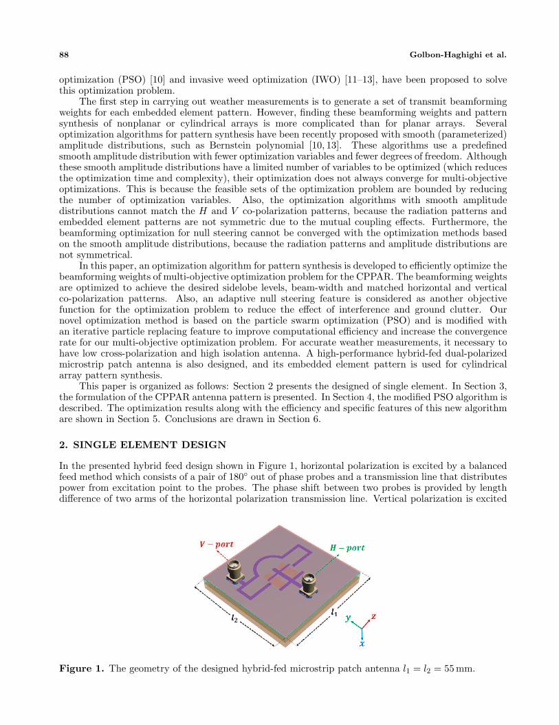
Figure 10 shows the co- and cross-polar radiation patterns in the vertical plane for H and Vpolarizations with 53 elements. The beamwidth for both H-pol and V -pol is designed to be 2◦. Figure 11shows the optimized 2D copolar radiation pattern for designed CPPAR. To achieve a cost-efficient designfor the CPPAR, the number of elements should be minimized. To minimize the number of elements forarray antennas, element spacing should be increased, which can cause the appearance of grating lobes.Therefore, we need to compromise between the number of elements and appearance of grating lobes,based on the specific case. It is clear that the 3-dB beamwidth will increase by decreasing the number
0 50 100 150
Zenith Angle , (degree)
-90
-80
-70
-60
-50
-40
-30
-20
-10
0
No
rmalized
Gain
(d
B)
Mask
H
V
V Cross
H Cross
-135 -95 -55 -15 25 65 105 135
Azimuth Angle , (degree)
-70
-60
-50
-40
-30
-20
-10
0
No
rmalized
Gain
(d
B)
Mask
H
V
V Cross
H Cross
(a) (b)
Figure 12. Optimized radiation pattern in (a) horizontal plane and (b) vertical plane for H and Vpolarizations with 20-degree elevation.
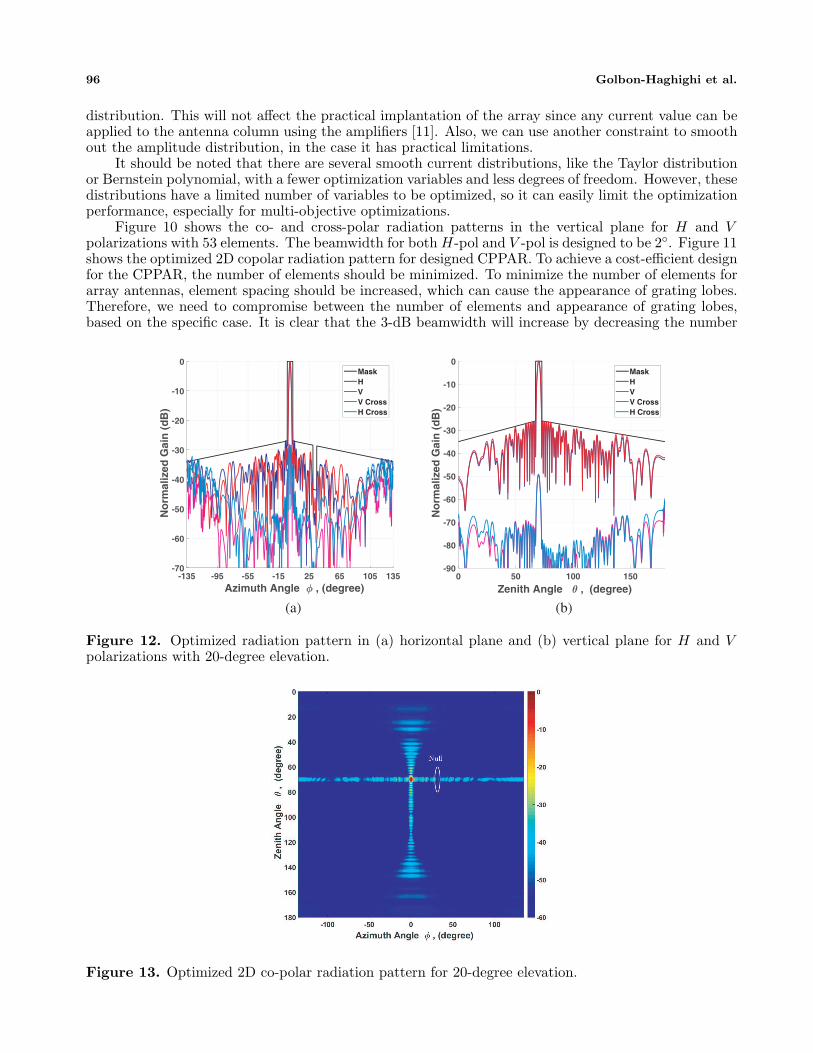
Figure 13. Optimized 2D co-polar radiation pattern for 20-degree elevation.

Progress In Electromagnetics Research M, Vol. 66, 2018 97
of elements in the vertical or horizontal planes.To study the performance of the proposed modified PSO algorithm for other elevations, a 20◦
elevation has been considered. Here, the modified PSO is designed to achieve the desired sidelobe level,beamwidth and matched co-polarization patterns, while the main beam is pointed to θ = 70◦. Also,a null is steered with 15 dB lower than the mask and between 30◦–35◦, as shown in Figure 12. Theradiation pattern in the horizontal and vertical planes for H and V polarizations are optimized forthe case where the main beam is pointed to θ = 70◦. It is clear that by increasing the scan angle inelevation, the beamwidth was slightly increased, for the same number of elements and side lobe levels.The 2D copolar radiation pattern for 20◦ elevation is shown in Figure 13. The optimization algorithmcan update the beamforming weights to have null steering for different directions and widths, if we haveinterference from more than one directions. To mitigate the back-to-back interference when multiplesimultaneous beams are formed and share the same frequency, a null can be designed at 180◦.
6. CONCLUSION
A modified PSO algorithm was applied to optimally design the cylindrical polarimetric phased arrayradar (CPPAR) antenna patterns for weather measurements. After minimizing the number of elementsof the CPPAR, the complex beamforming weights are optimized to achieve the desired radiation patternbased on the multi objective function. Simulation results show the performance of the modified PSOalgorithm in achieving desired sidelobe levels and beamwidth and matched co-polarization patterns, forboth broadside and off broadside directions. Also, an adaptive null steering feature is considered toreduce the effect of interference and ground clutter.
ACKNOWLEDGMENT
This work was supported by the National Oceanic and Atmospheric Administration under GrantsNA11OAR4320072 and NA16OAR4320115.
REFERENCES
1. Weber, M., J. Cho, J. Flavin, J. Herd, and M. Vai, “Multi-function phased array radar for US civil-sector surveillance needs,” The 32nd Conf. on Radar Meteorology, Albuquerque, NM, Oct. 24–29,2005.
2. Zrnic, D., J. Kimpel, D. Forsyth, A. Shapiro, G. Crain, R. Ferek, J. Heimmer, W. Benner,T. McNellis, and R. Vogt, “Agile-beam phased array radar for weather observations,” Bulletinof the American Meteorological Society, Vol. 88, No. 11, 1753–1766, 2007.
3. Zhang, G., Weather Radar Polarimetry, CRC Press, 2016.4. Saeidi-Manesh, H. and G. Zhang, “Characterization and optimization of cylindrical polarimetric
array antenna patterns for multi-mission applications,” Progress In Electromagnetics Research,Vol. 158, 49–61, 2017.
5. Golbon-Haghighi, M.-H., Y. Li, G. Zhang, and R. Doviak, “Detection of ground clutter fromweather radar using a dual-polarization and dual-scan method,” Atmosphere, Vol. 7, No. 6, 83,Jun. 2016.
6. Saeidi-Manesh, H., S. Karimkashi, G. Zhang, and R. J. Doviak, “High-isolation low cross-polarization phased-array antenna for mpar application,” Radio Science, Vol. 158, 49–61, 2017.
7. Saeidi-Manesh, H. and G. Zhang, “Cross-polarisation suppression in cylindrical array antenna,”Electronics Letters, Vol. 53, No. 9, 577–578, 2017.
8. Yang, J. O., Q. R. Yuan, F. Yang, H. J. Zhou, Z. P. Nie, and Z. Q. Zhao, “Synthesis ofconformal phased array with improved NSGA-II algorithm,” IEEE Transactions on Antennas andPropagation, Vol. 57, No. 12, 4006–4009, Dec. 2009.
9. Holland, J. H., “Genetic algorithms,” Scientific American, Vol. 267, No. 1, 66–73, 1992.

98 Golbon-Haghighi et al.
10. Boeringer, D. W. and D. H. Werner, “Efficiency-constrained particle swarm optimization ofa modified bernstein polynomial for conformal array excitation amplitude synthesis,” IEEETransactions on Antennas and Propagation, Vol. 53, No. 8, 2662–2673, 2005.
11. Karimkashi, S. and G. Zhang, “Optimizing radiation patterns of a cylindrical polarimetric phased-array radar for multimissions,” IEEE Transactions on Geoscience and Remote Sensing, Vol. 53,No. 5, 2810–2818, May 2015.
12. Saeidi-Manesh, H. and G. Zhang, “High-isolation, low cross-polarization, dual-polarization, hybridfeed microstrip patch array antenna for MPAR application,” IEEE Transactions on Antennas andPropagation, Vol. 66, No. 05, 2018, doi: 10.1109/TAP.2018.2811780.
13. Karimkashi, S. and G. Zhang, “An optimal design of a cylindrical polarimetric phased array radarfor weather sensing,” Radio Science, Vol. 47, No. 2, 2012.
14. Mailloux, R. J., Phased Array Antenna Handbook (Artech House Antennas and PropagationLibrary), Artech House, 2005.
15. Lei, L., G. Zhang, and R. J. Doviak, “Theoretical analysis of polarization characteristics for planarand cylindrical phased array radars,” AMS General Meeting in New Orleans, 2012.
16. Eberhart, R. and J. Kennedy, “A new optimizer using particle swarm theory,” Proceedings ofthe Sixth International Symposium on Micro Machine and Human Science, 1995, MHS’95, 39–43,IEEE, 1995.
17. Kennedy, J., “Particle swarm optimization,” Encyclopedia of Machine Learning, 760–766, Springer,2011.
18. Eberhart, R. C., Y. Shi, and J. Kennedy, Swarm Intelligence, Elsevier, 2001.19. Khodier, M. M. and M. Al-Aqeel, “Linear and circular array optimization: A study using particle
swarm intelligence,” Progress In Electromagnetics Research B, Vol. 15, 347–373, 2009.20. Golbon-Haghighi, M. H., B. Mahboobi, and M. Ardebilipour, “Linear pre-coding in MIMO-CDMA
relay networks,” Wireless Personal Communications, Vol. 79, No. 2, 1321–1341, Springer, Jul. 2014.21. Golbon-Haghighi, M. H., “Beamforming in wireless networks,” InTech Open, Book Chapter, 163–
192, ISBN 978-953-51-2833-5, Dec. 2016.22. Golbon-Haghighi, M. H., B. Mahboobi, and M. Ardebilipour, “Multiple antenna relay beamforming
for wireless peer to peer communications,” Journal of Information Systems and Telecommunication(JIST), 209–2015, 2013.