Embed Size (px)
Citation preview
Parul Polytechnic Institute Parul Polytechnic Institute
NAME OF SUBJECT : ECC
TOPIC : FILTERS
NAME OF FACULTY :HUTESH BAVISKAR

FILTERS A Power Supply Must Provide Ripple Free Source
Of Power From An A.C. Line. But The Output Of A Rectifier Circuit Contains Ripple Components In Addition To A D.C. Term. It Is Necessary To Include A Filter Between The Rectifier And The Loads In Order To Eliminate These Ripple Components.
Topic: FILTERS
Ripple Components Are High Frequency A.C. Signals In The D.C Output Of The Rectifier. These Are Not Desirable, So They Must Be Filtered. So Filter Circuits Are Used. Many Types Of Passive Filters Are In Use Such As.
Topic: FILTERS
TYPES OF FILTERS
1. Shunt Capacitor Filter2. Series Inductor Filters3. Choke Input Lc Filter4. Capacitor Input Lc Filter5. Pi-filter
Topic: FILTERS

SHUNT CAPACITOR FILTER This Type Of Filter Consists Of Large Value Of
Capacitor Connected Across The Load Resistor RL As Shown In Figure .
This Capacitor Offers A Low Reactance To The A.C. Components And Very High Impedance To D.C. So That The A.C.
Components In The Rectifier Output Find Low Reactance Path Through Capacitor And Only A Small Part Flows Through Rl, Producing Small Ripple At The Output As Shown In Figure.
Topic: FILTERS
Here Xc (=1/2πfc, The Impedance Of Capacitor) Should Be Smaller Than RL. Because, Current Should Pass Through C And C Should Get Charged.
If C Value Is Very Small, Xc Will Be Large And Hence Current Flows Through Rl Only And No Filtering Action Takes Place.
The Capacitor C Gets Charged When The Diode (In The Rectifier) Is Conducting And Gets Discharged (When The Diode Is Not Conducting) Through Rl.
Topic: FILTERS
When The Input Voltage = Is Greater 𝑣 𝑉𝑚 𝑠𝑖𝑛 𝜔𝑡Than The Capacitor Voltage, C Gets Charged.
When The Input Voltage Is Less Than That Of The Capacitor Voltage, C Will Discharge Through Rl.
The Stored Energy In The Capacitor Maintains The Load Voltage At A High Value For A Long Period.
Topic: FILTERS

The Diode Conducts Only For A Short Interval Of High Current.
The Waveforms Are As Shown In Figure 5.2. Capacitor Opposes Sudden Fluctuations In Voltage Across It.
So The Ripple Voltage Is Minimized.
Sub: BASIC ELECTRONICS Topic: FILTERS

CT FWR With Shunt Capacitor Filter
Rectifier With Shunt Capacitor Filter
The Discharging Of The Capacitor Depends Upon The Time Constant C.Rl.
Hence The Smoothness And The Magnitude Of Output Voltage Depend Upon The Value Of Capacitor C And Rl.
As The Value Of C Increases The Smoothness Of The Output Also Increases.
But The Maximum Value Of The Capacitor Is Limited By The Current Rating Of The Diode.
Topic: FILTERS

Also Decrease In The Value Of RL Increases The Load Current And Makes The Time Constant Smaller.
These Types Of Filters Are Used In Circuits With Small Load Current Like Transistor Radio Receivers, Calculators, Etc.
The Ripple Factor In Capacitor Filter Is Given B = 𝜸 Y𝟏 𝟒 𝟑𝒇𝑪𝑹𝑳 .
Topic: FILTERS

Advantage Disadvantage
Low Cost Capacitor Draws More Current
Small Size And Weight
Good Characteristics
Can Be Connected For Both HW And FW Rectifiers
Improved D.C. Output
Topic: FILTERS
SERIES INDUCTOR FILTER
The Working Of Series Inductor Filter Depends On The Inherent Property Of The Inductor To Oppose Any Variation In Current Intend To Take Place.
Fig Shows A Series Inductor Filter Connected At The Output Of A Fwr.
Here The Reactance Of The Inductor Is More For Ac Components And It Offers More Opposition To Them.
Topic: FILTERS

At The Same Time It Provides No Impedance For D.C. Component.
Therefore The Inductor Blocks A.C. Components In The Output Of The Rectifier And Allows Only D.C. Component To Flow Through RL.
Sub: BASIC ELECTRONICS Topic: FILTERS

Rectifier With Series Inductor Filter
Filter Output Waveform

The Action Of An Inductor Depends Upon The Current Through It And It Requires Current To Flow At All Time.
Therefore Filter Circuits Consisting Inductors Can Only Be Used Together With Full Wave Rectifiers.
In Inductor Filter An Increase In Load Current Will Improve The Filtering Action And Results In Reduced Ripple.
Topic: FILTERS

Series Inductor Filters Are Used In Equipments Of High Load Currents.
The Ripple Factor In Series Inductor Filter 𝜸 = 𝑹𝑳 𝟑 𝟐𝝎𝑳Advantages Disadvantages Sudden Changes In Current Is Smoothen Out
Reduced Output Voltage Due To The Drop Across The Inductor.
Improved Filtering Action At High Load Currents
Bulky And Large In Size
Note Suite For HWR Sub: BASIC ELECTRONICS Topic: FILTERS

CHOKE INPUT LC FILTER It Is A Combination Of Inductor And Capacitor
Filter. Here An Inductor Is Connected In Series And A
Capacitor Is Connected In Parallel To The Load As Shown In Fig .
As Discussed Earlier, A Series Inductor Filter Will Reduce The Ripple, When Increasing The Load Current.
Topic: FILTERS

But In Case Of A Capacitor Filter It Is Reverse That When Increasing Current The Ripple Also Increases.
So A Combination Of These Two Filters Would Make Ripple Independent Of Load Current.
The Ripple Factor Of A Chock Input Filter Is Given By = . 𝜸 𝟏 𝟏𝟗𝟒 𝑳𝑪 (By Taking F=50hz)
Sub: BASIC ELECTRONICS Topic: FILTERS

Rectifier with LC filter
output waveform of Rectifier with LC filter

Since The D.C. Resistance Of The Inductor Is Very Low It Allows D.C.
Current To Flow Easily Through It. The Capacitor Appears Open For D.C And So All D.C.
Component Passes Through It. The Capacitor Appears Open For D.C. And So All D.C
Components Passes Through The Load Resistor RL.
Topic: FILTERS
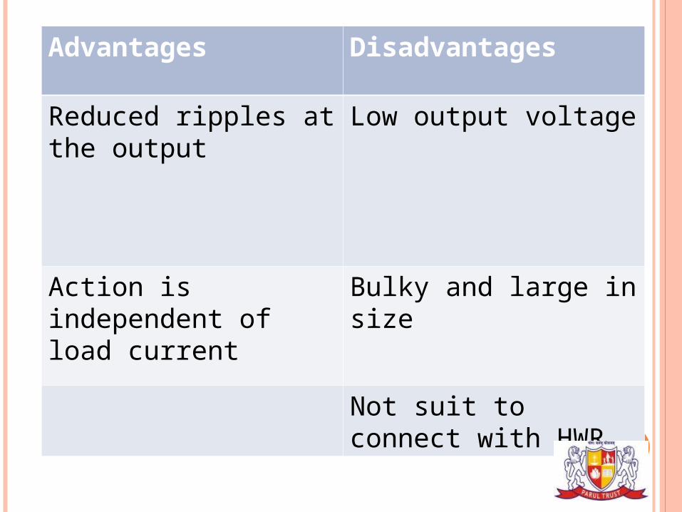
Advantages Disadvantages
Reduced ripples at the output
Low output voltage
Action is independent of load current
Bulky and large in size
Not suit to connect with HWR.
This filter is basically a capacitor filter followed by an LC filter as shown in fig .
Since its shape (C-L- C) is like the letter π it is called π – filter.
It is also called capacitor input filter because the rectifier feeds directly into the capacitor C1.
π – filter (Capacitor input filter) or CLC filter
Topic: FILTERS

Here the first capacitor C1 offers a low reactance to a.c.
component of rectifier output but provide more reactance to d.c components.
Therefore most of the a.c. components will bypass through C1 and the d.c. component flows through chock L.
The chock offers very high reactance to the a.c. component.
Topic: FILTERS

Thus It Blocks A.C. Components While Pass The D.C. The Capacitor C2 Bypasses Any Other A.C. Component Appears Across The Load And We Get Study D.C. Output As Shown Below.
The Ripple Factor In A Π-section Filter Is Given By = 𝛾2 1 2 𝑋𝐶 𝑋𝐶 𝑋𝐿𝑅𝐿
Topic: FILTERS

Rectifier With CLC Filter
Output Waveform Of Rectifier With CLC Filter
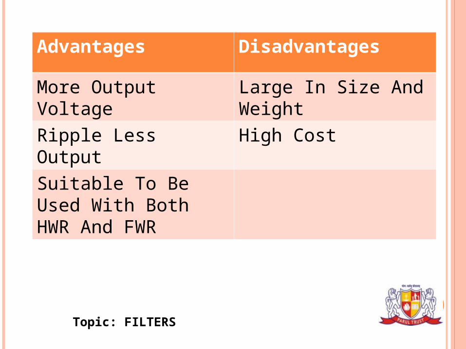
Advantages Disadvantages
More Output Voltage Large In Size And Weight
Ripple Less Output High Cost
Suitable To Be Used With Both HWR And FWR
Topic: FILTERS