Embed Size (px)
Citation preview
PARTHENOS – D6.1
1
PARTHENOS Cloud Infrastructure
PARTNER(s): CNR
DATE: 31 October 2016

2
PARTHENOS – D6.1
3
HORIZON 2020 - INFRADEV-4-2014/2015:
Grant Agreement No. 654119
PARTHENOS
Pooling Activities, Resources and Tools for Heritage E-research Networking,
Optimization and Synergies
NAME OF THE DELIVERABLE
Deliverable Number D6.1
Dissemination Level Public
Delivery date 31 October 2016
Status Final
Author(s)
Pasquale Pagano
Leonardo Candela
Massimiliano Assante
Luca Frosini
Paolo Manghi
Alessia Bardi
Fabio Sinibaldi
4
Project Acronym PARTHENOS
Project Full title Pooling Activities, Resources and Tools for Heritage E-
research Networking, Optimization and Synergies
Grant Agreement nr. 654119
Deliverable/Document Information
Deliverable nr./title D6.1 PARTHENOS Cloud Infrastructure
Document title PARTHENOS Cloud Infrastructure
Author(s) Pasquale Pagano, Massimiliano Assante, Leonardo Candela,
Luca Frosini, Paolo Manghi, Alessia Bardi and Fabio Sinibaldi
Dissemination
level/distribution
Public
Document History
Version/date Changes/approval Author/Approved by
V 0.1 30.06.16 Structure, table of contents,
introduction
Paolo Manghi, Pasquale
Pagano, Leonardo Candela
V 0.2 17.07.16 Enabling Technologies Pasquale Pagano
V 0.3 30.06.16 Storage Framework Alessia Bardi, Massimiliano
Assante, Fabio Sinibaldi
V 0.5 30.09.16 Content Cloud Framework Alessia Bardi
V 0.6 27.10.16 Analytics Framework Massimiliano Assante
V 0.7 24.11.16 Collaborative Framework Massimiliano Assante
V 0.8 12.12.16 Enabling Framework Luca Frosini, Pasquale
Pagano
Final 20/12/2016 FINAL version Pasquale Pagano
This work is licensed under the Creative Commons CC-BY License. To view a copy of the
license, visit https://creativecommons.org/licenses/by/4.0/
PARTHENOS – D6.1
5
Table of content
Table of Figures ........................................................................................................................................... 7
Executive Summary.................................................................................................................................... 8
Abbreviations ............................................................................................................................................... 9
1. Introduction ....................................................................................................................................... 10
1.1. Structure of this report .......................................................................................................................... 11
2. Cloud Infrastructure ....................................................................................................................... 12
2.1. Hardware Layer ........................................................................................................................................ 12
2.1.1. Enabling Technology ....................................................................................................................................... 12
2.1.2. Supporting Technology .................................................................................................................................. 13
2.1.2.1. Monitoring and Alerting System ............................................................................................................................. 13
2.1.2.2. Provisioning System ..................................................................................................................................................... 15
2.2. Enabling Framework .............................................................................................................................. 16
2.2.1. Overview .............................................................................................................................................................. 16
2.2.2. Key Features ....................................................................................................................................................... 17
2.2.3. Subsystems.......................................................................................................................................................... 18
2.2.3.1. Resource Registry ......................................................................................................................................................... 18
2.2.3.2. Resource Manager ........................................................................................................................................................ 20
2.2.3.3. Virtual Research Environment Manager ............................................................................................................ 21
2.2.3.4. Authentication and Authorization ......................................................................................................................... 22
2.2.3.5. Accounting ........................................................................................................................................................................ 27
2.3. Storage Framework ................................................................................................................................. 30
2.3.1. Overview .............................................................................................................................................................. 30
2.3.2. Key Features ....................................................................................................................................................... 30
2.3.3. Subsystems.......................................................................................................................................................... 31
2.3.3.1. File-Based Store System ............................................................................................................................................. 31
2.3.3.2. Metadata Store System ............................................................................................................................................... 32
2.3.3.3. Spatial Data Repositories ........................................................................................................................................... 33
2.4. Analytics Framework ............................................................................................................................. 35
2.4.1. Overview .............................................................................................................................................................. 35
2.4.2. Key Features ....................................................................................................................................................... 35
2.4.3. Subsystems.......................................................................................................................................................... 36
2.4.3.1. Data Miner System ........................................................................................................................................................ 36
2.4.3.2. Smart Executor System ............................................................................................................................................... 38
6
2.5. Content Cloud Framework .................................................................................................................... 39
2.5.1. Overview .............................................................................................................................................................. 39
2.5.2. Key Features ....................................................................................................................................................... 40
2.5.3. Subsystems.......................................................................................................................................................... 41
2.5.3.1. Workflow Management System .............................................................................................................................. 42
2.5.3.2. Data Source Management System .......................................................................................................................... 42
2.5.3.3. Data Collection System ............................................................................................................................................... 43
2.5.3.4. Data Transformation System ................................................................................................................................... 44
2.5.3.5. Data Provision System ................................................................................................................................................ 44
2.6. Collaborative Framework ..................................................................................................................... 45
2.6.1. Overview .............................................................................................................................................................. 45
2.6.2. Key Features ....................................................................................................................................................... 46
2.6.3. Subsystems.......................................................................................................................................................... 46
2.6.3.1. Social Networking System ......................................................................................................................................... 46
2.6.3.2. Shared Workspace System ........................................................................................................................................ 47
2.6.3.3. User Management System ......................................................................................................................................... 48
3. Conclusions ........................................................................................................................................ 50
PARTHENOS – D6.1
7
Table of Figures
Figure 1: High-level architecture of the PARTHENOS infrastructure ................................. 11
Figure 2: Nagios Status Report and Availability Report for the Accounting Cluster ........... 14
Figure 3: Ganglia Aggregated View for the Accounting Cluster ......................................... 15
Figure 4: Enabling Framework Architecture ....................................................................... 17
Figure 5: Resource Registry Architecture .......................................................................... 19
Figure 6: Resource Manager Architecture ......................................................................... 21
Figure 7: VRE Manager Architecture ................................................................................. 22
Figure 8: Authorization Architecture ................................................................................... 25
Figure 9: Accounting Architecture ...................................................................................... 28
Figure 10: File-Based System Architecture ........................................................................ 32
Figure 11: Spatial Data Repositories Architecture ............................................................. 34
Figure 12: Data Miner System Architecture ....................................................................... 37
Figure 13: Smart Executor System Architecture ................................................................ 38
Figure 14: D-NET Aggregative Infrastructure Architecture................................................. 40
Figure 15: GUI for Data Source Management ................................................................... 43
Figure 16: Social Networking System Architecture ............................................................ 47
Figure 17: Shared Workspace System Architecture .......................................................... 48
8
Executive Summary
This report describes the PARTHENOS e-infrastructure architecture: the hardware and the
services. Hardware is organized as a dynamic cloud of virtual machines, supporting
computation and storage, while the services are organized into e-infrastructure
middleware, storage, and end user services.
PARTHENOS – D6.1
9
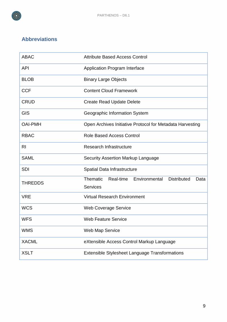
Abbreviations
ABAC Attribute Based Access Control
API Application Program Interface
BLOB Binary Large Objects
CCF Content Cloud Framework
CRUD Create Read Update Delete
GIS Geographic Information System
OAI-PMH Open Archives Initiative Protocol for Metadata Harvesting
RBAC Role Based Access Control
RI Research Infrastructure
SAML Security Assertion Markup Language
SDI Spatial Data Infrastructure
THREDDS Thematic Real-time Environmental Distributed Data
Services
VRE Virtual Research Environment
WCS Web Coverage Service
WFS Web Feature Service
WMS Web Map Service
XACML eXtensible Access Control Markup Language
XSLT Extensible Stylesheet Language Transformations
10
1. Introduction
The PARTHENOS e-infrastructure architecture consists of a hardware layer and a service
layer. The hardware layer is organized as a dynamic pool of virtual machines, supporting
computation and storage, while the services layer is organized into e-infrastructure
middleware, storage, and end user services. The hardware layer consists of an OpenStack
installation, supporting the deployment of services in the upper layer by provision of
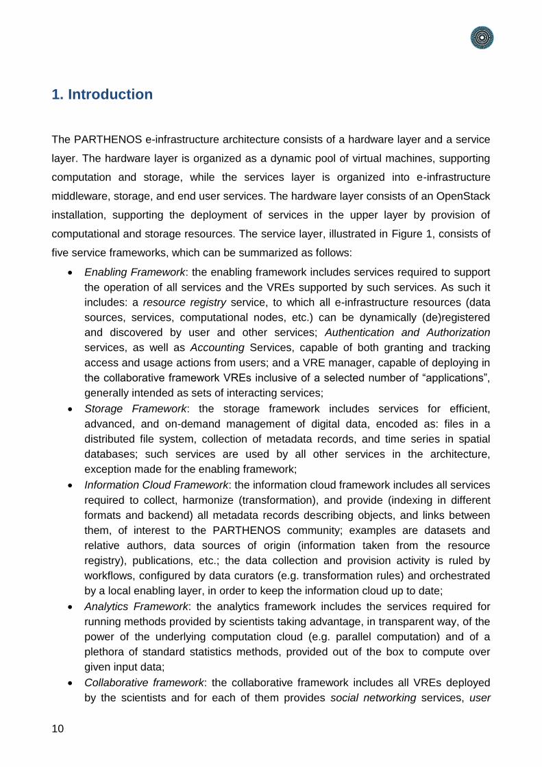
computational and storage resources. The service layer, illustrated in Figure 1, consists of
five service frameworks, which can be summarized as follows:
Enabling Framework: the enabling framework includes services required to support
the operation of all services and the VREs supported by such services. As such it
includes: a resource registry service, to which all e-infrastructure resources (data
sources, services, computational nodes, etc.) can be dynamically (de)registered
and discovered by user and other services; Authentication and Authorization
services, as well as Accounting Services, capable of both granting and tracking
access and usage actions from users; and a VRE manager, capable of deploying in
the collaborative framework VREs inclusive of a selected number of “applications”,
generally intended as sets of interacting services;
Storage Framework: the storage framework includes services for efficient,
advanced, and on-demand management of digital data, encoded as: files in a
distributed file system, collection of metadata records, and time series in spatial
databases; such services are used by all other services in the architecture,
exception made for the enabling framework;
Information Cloud Framework: the information cloud framework includes all services
required to collect, harmonize (transformation), and provide (indexing in different
formats and backend) all metadata records describing objects, and links between
them, of interest to the PARTHENOS community; examples are datasets and
relative authors, data sources of origin (information taken from the resource
registry), publications, etc.; the data collection and provision activity is ruled by
workflows, configured by data curators (e.g. transformation rules) and orchestrated
by a local enabling layer, in order to keep the information cloud up to date;
Analytics Framework: the analytics framework includes the services required for
running methods provided by scientists taking advantage, in transparent way, of the
power of the underlying computation cloud (e.g. parallel computation) and of a
plethora of standard statistics methods, provided out of the box to compute over
given input data;
Collaborative framework: the collaborative framework includes all VREs deployed
by the scientists and for each of them provides social networking services, user
PARTHENOS – D6.1
11
management services, shared workspace services, and WebUI access to the
information cloud and to the analytics framework, via analytics laboratory services.
Figure 1: High-level architecture of the PARTHENOS infrastructure
1.1. Structure of this report
This report is structured in two sections: Section 2 on the Cloud Infrastructure and Section
3, which concludes the report. More in detail, Section 2 is organized in six subsections:
section Enabling Technology, for the hardware (storage and computation) layer, and
sections Enabling Framework, Storage Framework, Analytics Framework, and Content
Cloud Framework, and Collaborative Framework for the service layer.
12
2. Cloud Infrastructure
The PARTHENOS e-infrastructure architecture consists of a hardware layer and a service
layer.
The hardware layer is organized as a dynamic pool of virtual machines, supporting
computation and storage. The operations and management of those resources is
performed via a set of enabling technologies selected to ensure availability and reliability
of the infrastructure while guaranteeing reduction of costs of ownership and a set of
supporting technologies selected to ensure secure monitoring, alerting and provisioning.
The services layer is organized into layered software frameworks that increasingly hide the
complexity of the cloud-based infrastructure.
2.1. Hardware Layer
2.1.1. Enabling Technology
The following well-known technologies have been selected to manage the PARTHENOS
e-infrastructure hardware resources:
a. Ceph, http://www.ceph.com, has been selected as block storage since it is Amazon S3
compatible and OpenStack Swift compatible, it is completely distributed, and it may
even use disposable server hardware;
b. Openstack, http://www.openstack.org, has been selected as cloud-computing software
platform. It uses Ceph as storage;
c. ManageIQ, http://manageiq.org, has been selected to manage quotas, permissions,
production vs devel environments.
The Ceph Storage offers object, block, and file storage under a unified system. It has
been designed to provide excellent performance, reliability and scalability. It supports rapid
provisioning of massively scalable cloud storage and enables computation intensive
workloads. It provides access to the storage via application written in Java, Python, Ruby,
C, etc. It scales to Petabytes and it offers linear scaling with linear performance increase.
The Openstack, open source cloud computing platform, provides Infrastructure-as-a-
Service (IaaS). OpenStack lets the PARTHENOS Enabling Framework deploys virtual
machines and other instances that handle different tasks on the fly. It makes horizontal
scaling affordable, which means that services that benefit from running concurrently can
PARTHENOS – D6.1
13
easily serve more or fewer tasks – issued either by users or by other services - on the fly
by just spinning up more service instances.
The ManageIQ open source platform is a management framework for infrastructure
integrating resources from several data centres. It has been designed to manage small
and large infrastructure, and supports private data centers exploiting virtual machines and
even public clouds. ManageIQ supports continuously discover of the latest state of the
infrastructure, simplifies the enforcement of policies across the environment, and it
optimizes the performance and utilization of the hardware resources.
2.1.2. Supporting Technology
2.1.2.1. Monitoring and Alerting System
The PARTHENOS e-infrastructure is currently comprised of 212 servers. This means that
neither all of them are exploited at the same time nor that all of them have to be active
concurrently to deliver specific service capabilities. Servers are allocated dynamically in
accordance with the Cloud-computing approach and are activated/deactivated in response
to load, failures, changes in policies and deployment strategies. This complexity requires
proper monitoring infrastructure to check the servers and the services running on the
servers and to proper alert when failures are identified. The PARTHENOS e-infrastructure
exploits two well-known technology to perform this task: Nagios and Ganglia.
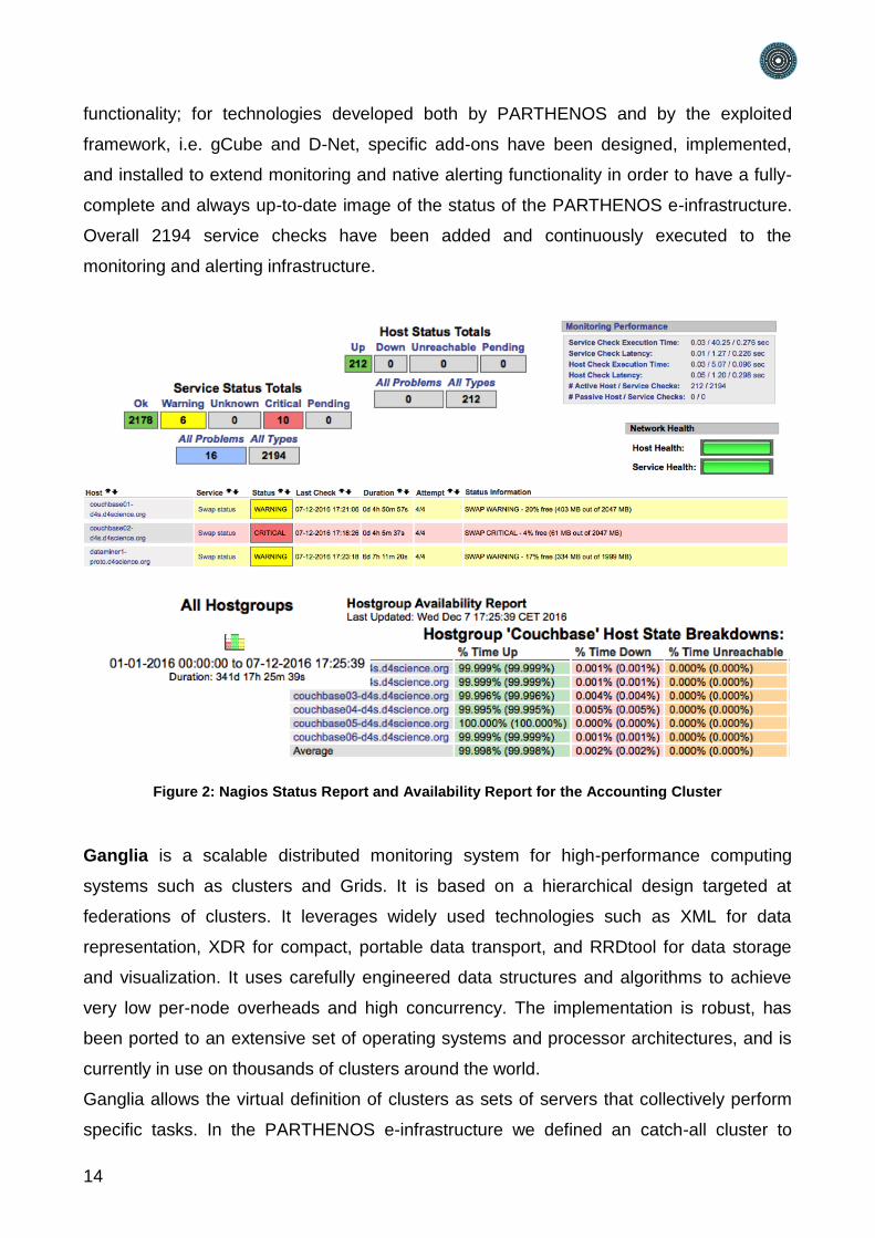
Nagios is an enterprise-class monitoring and alerting solution that provides extended
insight of the infrastructure enabling quickly identification and resolution of problems
before they may affect critical business processes. It provides monitoring of all mission-
critical infrastructure components including applications, services, operating systems,
network protocols, systems metrics, and network infrastructure. Nagios provides a central
view of operations, network, and business processes running on the infrastructure.
Powerful dashboards provide at-a-glance access to powerful monitoring information and
third-party data. Views provide users with quick access to the information they find most
useful, and to spot problems easily with advanced data visualization reports. Moreover,
alerts are sent to infrastructure managers and the Parthenos quality assurance task force
via email or mobile text messages, providing them with outage details so they can start
resolving issues immediately. Finally, multiple APIs provide for simple integration with in-
house and third-party applications. In particular, for well-known technologies exploited in
the PARTHENOS e-infrastructure, e.g. MongoDB, Cassandra, Couchbase, PostgreSQL,
etc, existing add-ons have been installed to extend monitoring and native alerting
14
functionality; for technologies developed both by PARTHENOS and by the exploited
framework, i.e. gCube and D-Net, specific add-ons have been designed, implemented,
and installed to extend monitoring and native alerting functionality in order to have a fully-
complete and always up-to-date image of the status of the PARTHENOS e-infrastructure.
Overall 2194 service checks have been added and continuously executed to the
monitoring and alerting infrastructure.
Figure 2: Nagios Status Report and Availability Report for the Accounting Cluster
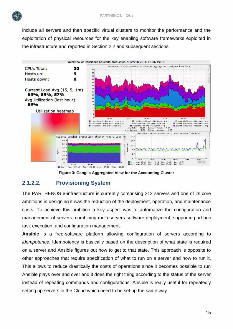
Ganglia is a scalable distributed monitoring system for high-performance computing
systems such as clusters and Grids. It is based on a hierarchical design targeted at
federations of clusters. It leverages widely used technologies such as XML for data
representation, XDR for compact, portable data transport, and RRDtool for data storage
and visualization. It uses carefully engineered data structures and algorithms to achieve
very low per-node overheads and high concurrency. The implementation is robust, has
been ported to an extensive set of operating systems and processor architectures, and is
currently in use on thousands of clusters around the world.
Ganglia allows the virtual definition of clusters as sets of servers that collectively perform
specific tasks. In the PARTHENOS e-infrastructure we defined an catch-all cluster to
PARTHENOS – D6.1
15
include all servers and then specific virtual clusters to monitor the performance and the
exploitation of physical resources for the key enabling software frameworks exploited in
the infrastructure and reported in Section 2.2 and subsequent sections.
Figure 3: Ganglia Aggregated View for the Accounting Cluster
2.1.2.2. Provisioning System
The PARTHENOS e-infrastructure is currently comprising 212 servers and one of its core
ambitions in designing it was the reduction of the deployment, operation, and maintenance
costs. To achieve this ambition a key aspect was to automatize the configuration and
management of servers, combining multi-servers software deployment, supporting ad hoc
task execution, and configuration management.
Ansible is a free-software platform allowing configuration of servers according to
idempotence. Idempotency is basically based on the description of what state is required
on a server and Ansible figures out how to get to that state. This approach is opposite to
other approaches that require specification of what to run on a server and how to run it.
This allows to reduce drastically the costs of operations since it becomes possible to run
Ansible plays over and over and it does the right thing according to the status of the server
instead of repeating commands and configurations. Ansible is really useful for repeatedly
setting up servers in the Cloud which need to be set up the same way.
16
In order to exploit Ansible in the PARTHENOS e-infrastructure, it was needed to define a
number of resources and configuration scripts that then are exploited by Ansible to
perform the activities
inventories - list of servers to configure and maintain
playbooks - collection of plays, or simply a collection of roles for a 1-play playbook
plays - a collection of roles
roles - generally, one service (like postgres or nginx)
tasks - a command that Ansible runs via its modules, like a task for installing a
package via apt-get
handlers - like tasks that get called when other tasks request them via notifications.
Typically used to restart services.
host vars - variables that apply to one collection of hosts
modules - provided by Ansible to do things like configure MySQL (mysql module),
install via apt-get (apt module), copy over files (file module), add users (user
module).
Overall, to manage the PARTHENOS e-infrastructure 197 roles have been defined.
2.2. Enabling Framework
2.2.1. Overview
The Enabling Framework is realized by a combination of services and libraries powered by
the gCube System open-source project. Those services promote the optimal exploitation
of the resources available in the PARTHENOS Cloud Infrastructure and the integration of
technology external to it. They insulate as much as possible the management of the
infrastructure from the data and the data management services that are hosted in or
accessible through the infrastructure itself.
The motto at the heart of the management facilities is less dependencies for more
management meaning that the requirements posed to resources (even independent
resources) to be managed are minimal, close to zero in some cases. All the implemented
solutions are prioritized in order to pursue this goal.
Towards new directions of openness and interoperability called by our growing community,
management facilities move along:
adoption of standards
support for new software platforms by implementing a zero-dependency approach
to software management.
PARTHENOS – D6.1
17
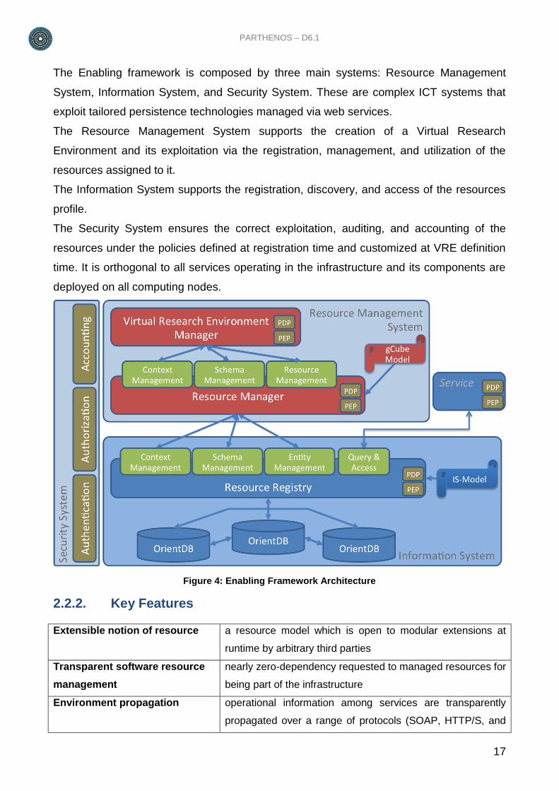
The Enabling framework is composed by three main systems: Resource Management
System, Information System, and Security System. These are complex ICT systems that
exploit tailored persistence technologies managed via web services.
The Resource Management System supports the creation of a Virtual Research
Environment and its exploitation via the registration, management, and utilization of the
resources assigned to it.
The Information System supports the registration, discovery, and access of the resources
profile.
The Security System ensures the correct exploitation, auditing, and accounting of the
resources under the policies defined at registration time and customized at VRE definition
time. It is orthogonal to all services operating in the infrastructure and its components are
deployed on all computing nodes.
Figure 4: Enabling Framework Architecture
2.2.2. Key Features
Extensible notion of resource a resource model which is open to modular extensions at
runtime by arbitrary third parties
Transparent software resource
management
nearly zero-dependency requested to managed resources for
being part of the infrastructure
Environment propagation operational information among services are transparently
propagated over a range of protocols (SOAP, HTTP/S, and
18
more)
Dynamic Deployment and
Optimal Resource (re)Allocation
remote deployment and (re-)configuration of resources
across the infrastructure
Resource lifetime management complete running of the entire lifetime of resources ranging
from creation and publication to discovery, access and
consumption
Self-elastic management dynamic resource provisioning to meet peaks and lows in
demand
Interoperability, openness and
integration at software level
third-parties software can be added to the infrastructure at
runtime
Support to standards crucial functionalities are accessible via recognized
standards in order to enhance interoperability
2.2.3. Subsystems
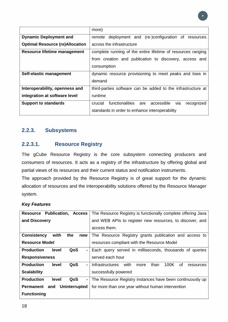
2.2.3.1. Resource Registry
The gCube Resource Registry is the core subsystem connecting producers and
consumers of resources. It acts as a registry of the infrastructure by offering global and
partial views of its resources and their current status and notification instruments.
The approach provided by the Resource Registry is of great support for the dynamic
allocation of resources and the interoperability solutions offered by the Resource Manager
system.
Key Features
Resource Publication, Access
and Discovery
The Resource Registry is functionally complete offering Java
and WEB APIs to register new resources, to discover, and
access them.
Consistency with the new
Resource Model
The Resource Registry grants publication and access to
resources compliant with the Resource Model
Production level QoS -
Responsiveness
Each query served in milliseconds, thousands of queries
served each hour
Production level QoS -
Scalability
Infrastructures with more than 100K of resources
successfully powered
Production level QoS -
Permanent and Uninterrupted
Functioning
The Resource Registry instances have been continuously up
for more than one year without human intervention
PARTHENOS – D6.1
19
Flexible deployment scenarios The Resource Registry components can be deployed in
several ways, to best fit the needs of the infrastructure or a
specific community
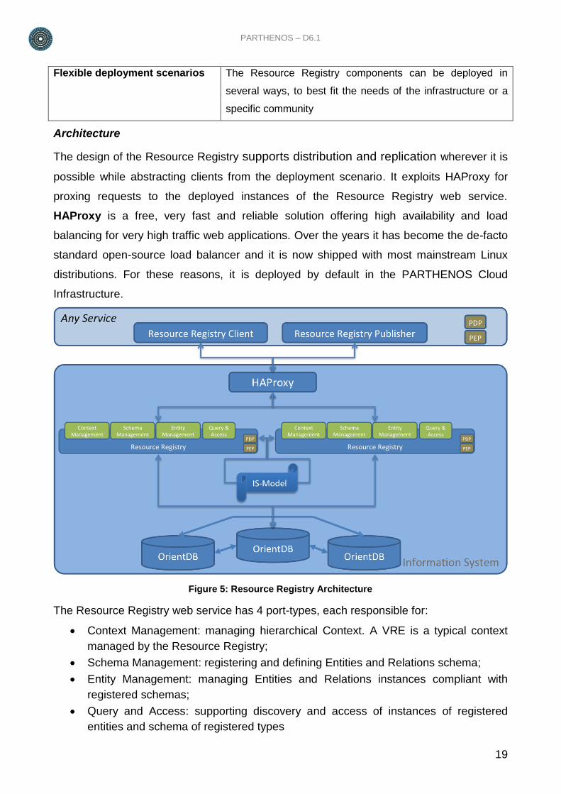
Architecture
The design of the Resource Registry supports distribution and replication wherever it is
possible while abstracting clients from the deployment scenario. It exploits HAProxy for
proxing requests to the deployed instances of the Resource Registry web service.
HAProxy is a free, very fast and reliable solution offering high availability and load
balancing for very high traffic web applications. Over the years it has become the de-facto
standard open-source load balancer and it is now shipped with most mainstream Linux
distributions. For these reasons, it is deployed by default in the PARTHENOS Cloud
Infrastructure.
Figure 5: Resource Registry Architecture
The Resource Registry web service has 4 port-types, each responsible for:
Context Management: managing hierarchical Context. A VRE is a typical context
managed by the Resource Registry;
Schema Management: registering and defining Entities and Relations schema;
Entity Management: managing Entities and Relations instances compliant with
registered schemas;
Query and Access: supporting discovery and access of instances of registered
entities and schema of registered types
20
Every port-type is exposed with a REST API.
The Resource Registry web service is stateless making possible to replicate it horizontally.
2.2.3.2. Resource Manager
The Resource Manager is responsible for providing Resources compliant with the gCube-
Model. In fact, this service is the only one entitled to perform operations on the Resource
Registry. It does so by exposing three port types:
1. Context Management enables Resource Registry context management by checking
if the requester has the proper role/rights to do the requested action.
2. Schema Management enables schema management on Resource Registry by
checking if the requester has the proper role/rights to do it;
3. Resource Management: enables to manage Resource instances by checking if:
a. the requester has the proper role/rights to do the requested action;
b. the action can be performed looking at the policies attached to the entities
and relation instances;
c. the action involves other entities or relations.
When all these checks are performed, and if and only if the action is feasible, the
Resource Manager translates the incoming request in one or more outgoing requests to
the Resource Registry service.
Key Features
Resource Publication, Access
and Discovery
The Resource Manager offers Java and WEB APIs to register
new resource types and instances.
Consistency with the gCube
Model
The Resource Registry grants publication and access to
resources compliant with the gCube Model at Resource level.
PARTHENOS – D6.1
21
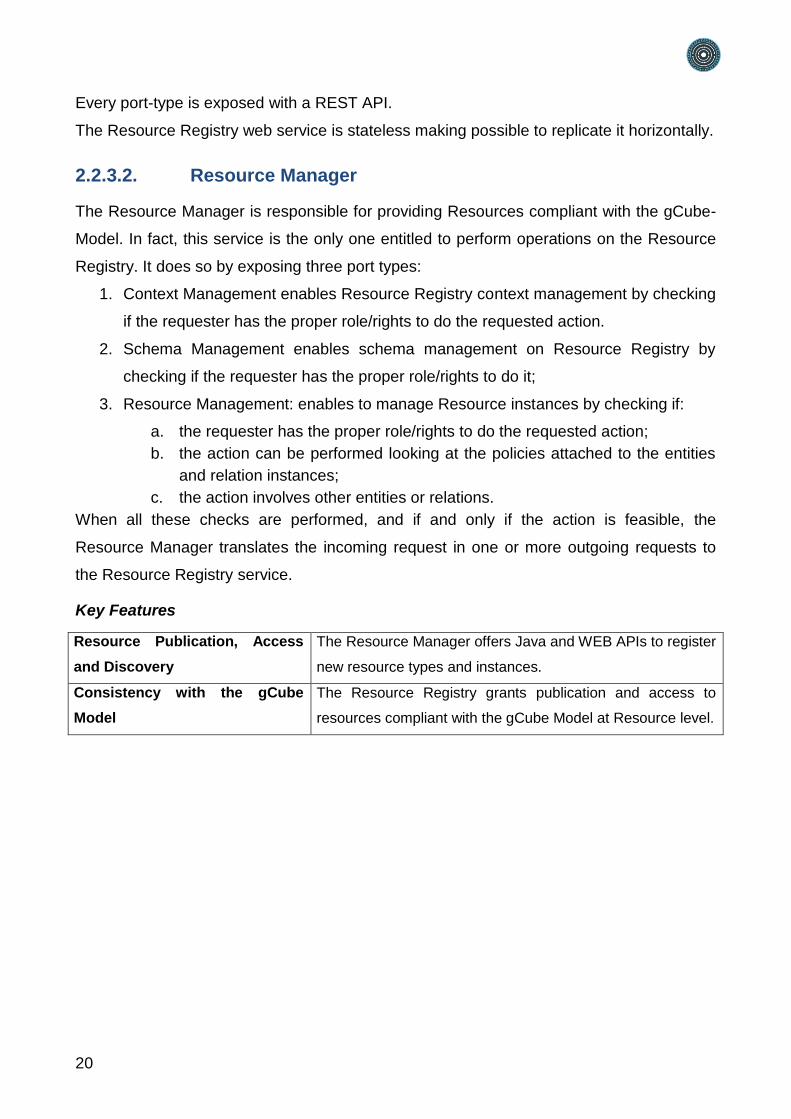
Architecture
Figure 6: Resource Manager Architecture
As depicted in Figure 6: Resource Manager Architecture, the Resource Manager uses the
Resource Registry Client to query the Resource registry and get the actual knowledge of
the infrastructure.
When the Resource Manager receives a request, once the proper checks have been
performed, it uses the Resource Registry publisher to make the request effective.
Both Resource Registry Client and Publisher interact with one of the instances of
Resource Registry through HA-Proxy.
2.2.3.3. Virtual Research Environment Manager
VRE Manager is responsible for providing context guarantees based on the gCube-Model.
The VRE Manager operates on the PARTHENOS Cloud Infrastructure by using
components of:
the enabling technologies such as Resource Manager;
supporting technologies such as Provisioning System.
The VRE Manager contacts the Resource Registry to get a current view of the
infrastructure; uses the provisioning system to deploy/undeploy services and data; asks
the Resource Manager to update the infrastructure state consistently.
Key Features
Context Management The VRE Manager offers Java and WEB APIs to create, edit,
and delete security context, i.e. Virtual Research
Environment.
22
Consistency with the gCube
Model
The VRE Manager grants publication and access to
resources compliant with the gCube Model at context level.
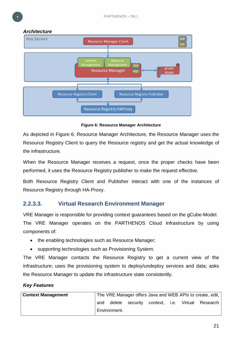
Architecture
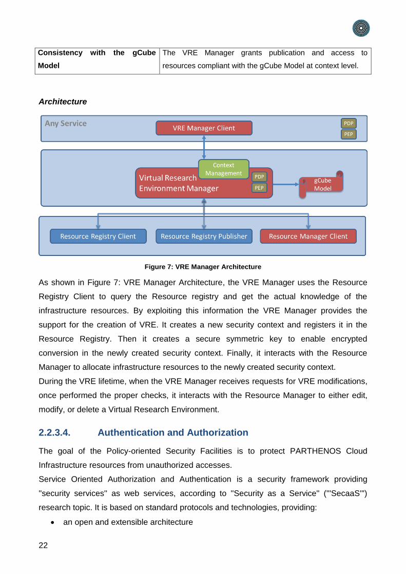
Figure 7: VRE Manager Architecture
As shown in Figure 7: VRE Manager Architecture, the VRE Manager uses the Resource
Registry Client to query the Resource registry and get the actual knowledge of the
infrastructure resources. By exploiting this information the VRE Manager provides the
support for the creation of VRE. It creates a new security context and registers it in the
Resource Registry. Then it creates a secure symmetric key to enable encrypted
conversion in the newly created security context. Finally, it interacts with the Resource
Manager to allocate infrastructure resources to the newly created security context.
During the VRE lifetime, when the VRE Manager receives requests for VRE modifications,
once performed the proper checks, it interacts with the Resource Manager to either edit,
modify, or delete a Virtual Research Environment.
2.2.3.4. Authentication and Authorization
The goal of the Policy-oriented Security Facilities is to protect PARTHENOS Cloud
Infrastructure resources from unauthorized accesses.
Service Oriented Authorization and Authentication is a security framework providing
''security services'' as web services, according to ''Security as a Service'' ('''SecaaS''')
research topic. It is based on standard protocols and technologies, providing:
an open and extensible architecture
PARTHENOS – D6.1
23
interoperability with external infrastructures and domains, obtaining, if required, also
so-called ''Identity Federation''
total isolation from the enabling framework and technologies: zero dependencies in
both the directions
The Policy-oriented Security Facilities are powered by the gCube Authorization framework.
The gCube Authorization framework is a token-based authorization system. The token
is a string generated on request by the Authorization service for identification purposes
and associated with every entity interacting with the infrastructure (users or services).
The token is passed in every call and is automatically propagated in the lower layers.
The token can be passed to a service in 3 ways:
using the HTTP-header: adding the value ("gcube-token","{your-token}") to the
header parameters
using the query-string: adding gcube-token={your-token} to the existing query-string
logging via the default authentication widget showed by the browser using your
username as username and your token as password.
The personal token can be retrieved using the token widget deployed on every
environment of the portal.
This framework is compliant with the Attribute-based access control (ABAC) that defines
an access control paradigm whereby access rights are granted to users through the use of
policies which combine attributes together.
ABAC defines access control based on attributes that describe:
the requesting entity (either the user or the service),
the targeted resource (either the service or the resource),
the desired action (read, write, delete, execute),
and environmental or contextual information (either the VRE or the VO where the
operation is executed).
ABAC is a logical access control model that is distinguishable because it controls access
to objects by evaluating rules against the attributes of the entities (requesting entity or
target resource) actions and the environment relevant to a request. ABAC relies upon the
evaluation of attributes of the requesting entity, attributes of the targeted resource,
environment conditions, and a formal relationship or access control rule defining the
allowable operations for entity-resource attribute and environment condition combinations.
The Authorization framework is compliant with the XACML reference architecture. XACML
is the OASIS standard for fine-grained authorization management based on the concept of
24
Attribute-based access control (ABAC), where access control decisions are made based
on attributes associated with relevant entities while operating in a given operational
context, a natural evolution from Role Based Access Control (RBAC).
Key Features
Security as a Service Authentication and Authorization provided by web services
called by resource management modules
Flexible authentication model The user is not requested to have personal digital certificates
Attribute-based Access Control A generic way to manage access: access control decisions
are based on one or more attributes
Support to different categories
of attributes
User related attributes (e.g. roles) and environment related
attributes (e.g. context)
Modularity Composed by different modules: each module has a well-
defined scope and provides well-defined services
Support to standards All the operations delivered by the facilities are built atop of
recognized standards
High performance The design and architectural choices have been made
paying great attention to performances
Resource Usage Tracking Administrators and users can monitor applications resources
usage
Architecture
The XACML standard proposes a reference architecture with commonly accepted names
for the various entities involved in the architecture. The nomenclature is not new (SAML
uses similar names to describe entities in its ecosystem), nor is the architecture
complicated, allowing for easier common base of understanding of the standard. Five
modules compose it:
Policy Administration Point (PAP) - Point which manages access authorization
policies
Policy Decision Point (PDP) - Point which evaluates access requests against
authorization policies before issuing access decisions
Policy Enforcement Point (PEP) - Point which intercepts user's access request to a
resource, makes a decision request to the PDP to obtain the access decision (i.e.
access to the resource is approved or rejected), and acts on the received decision
Policy Information Point (PIP) - The system entity that acts as a source of attribute
values (i.e. a resource, subject, environment)
PARTHENOS – D6.1
25
Policy Retrieval Point (PRP) - Point where the XACML access authorization policies
are stored, typically a database or the filesystem.
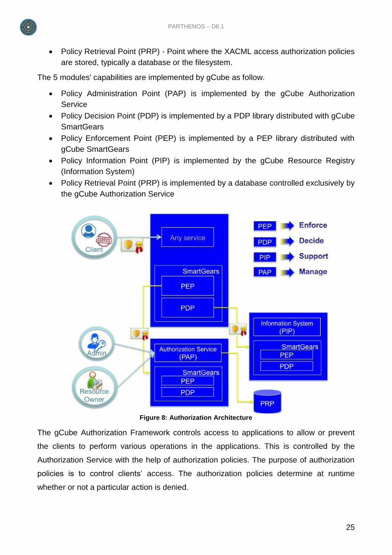
The 5 modules' capabilities are implemented by gCube as follow.
Policy Administration Point (PAP) is implemented by the gCube Authorization
Service
Policy Decision Point (PDP) is implemented by a PDP library distributed with gCube
SmartGears
Policy Enforcement Point (PEP) is implemented by a PEP library distributed with
gCube SmartGears
Policy Information Point (PIP) is implemented by the gCube Resource Registry
(Information System)
Policy Retrieval Point (PRP) is implemented by a database controlled exclusively by
the gCube Authorization Service
Figure 8: Authorization Architecture
The gCube Authorization Framework controls access to applications to allow or prevent
the clients to perform various operations in the applications. This is controlled by the
Authorization Service with the help of authorization policies. The purpose of authorization
policies is to control clients’ access. The authorization policies determine at runtime
whether or not a particular action is denied.
26
All the policies are used to DENY to a client an operation in a specific context. Two types
of policy are supported:
User2Service (U2S)
Service2Service (S2S)
The U2S policies are used to deny to a user or a role the access to specific service or
class of services. The S2S policies are used to deny to a service or a class of services the
access to specific service or class of services. To make easier the possibility to allow
access only to few clients except restriction clause can be added to the policies.
For every policy, a specific ACTION, i.e. Access, Write, Delete, and Execute, can be
specified (if supported from the service) otherwise all the ACTION will be denied.
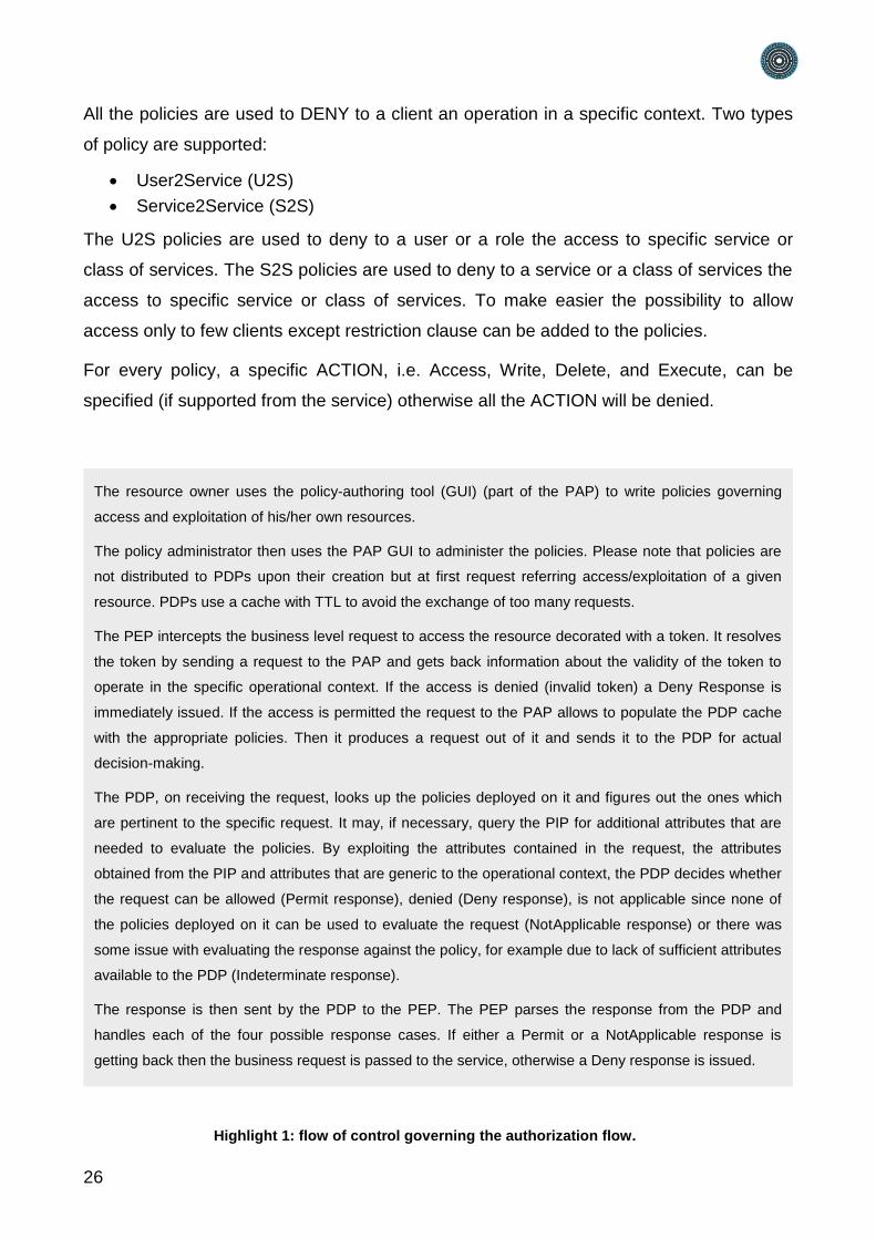
The resource owner uses the policy-authoring tool (GUI) (part of the PAP) to write policies governing
access and exploitation of his/her own resources.
The policy administrator then uses the PAP GUI to administer the policies. Please note that policies are
not distributed to PDPs upon their creation but at first request referring access/exploitation of a given
resource. PDPs use a cache with TTL to avoid the exchange of too many requests.
The PEP intercepts the business level request to access the resource decorated with a token. It resolves
the token by sending a request to the PAP and gets back information about the validity of the token to
operate in the specific operational context. If the access is denied (invalid token) a Deny Response is
immediately issued. If the access is permitted the request to the PAP allows to populate the PDP cache
with the appropriate policies. Then it produces a request out of it and sends it to the PDP for actual
decision-making.
The PDP, on receiving the request, looks up the policies deployed on it and figures out the ones which
are pertinent to the specific request. It may, if necessary, query the PIP for additional attributes that are
needed to evaluate the policies. By exploiting the attributes contained in the request, the attributes
obtained from the PIP and attributes that are generic to the operational context, the PDP decides whether
the request can be allowed (Permit response), denied (Deny response), is not applicable since none of
the policies deployed on it can be used to evaluate the request (NotApplicable response) or there was
some issue with evaluating the response against the policy, for example due to lack of sufficient attributes
available to the PDP (Indeterminate response).
The response is then sent by the PDP to the PEP. The PEP parses the response from the PDP and
handles each of the four possible response cases. If either a Permit or a NotApplicable response is
getting back then the business request is passed to the service, otherwise a Deny response is issued.
Highlight 1: flow of control governing the authorization flow.
PARTHENOS – D6.1
27
2.2.3.5. Accounting
Accounting is defined as the recording, summarizing, and classifying of service invocations
and other events, e.g. storage of data, systematically. Accountancy, in a simpler sense, is
the procedure of communicating and translating raw data from the infrastructure operation
to its managers and stakeholders.
Key Features
open and extensible accounting
model
the underlying accounting model is flexible to adapt to
diverse provider needs
highly modular and extensible
architecture
the entire subsystem comprise a large number of
components clearly separating the functional constituents
multiple options for storage the subsystem can rely on an array of diverse solutions for
actually storing records
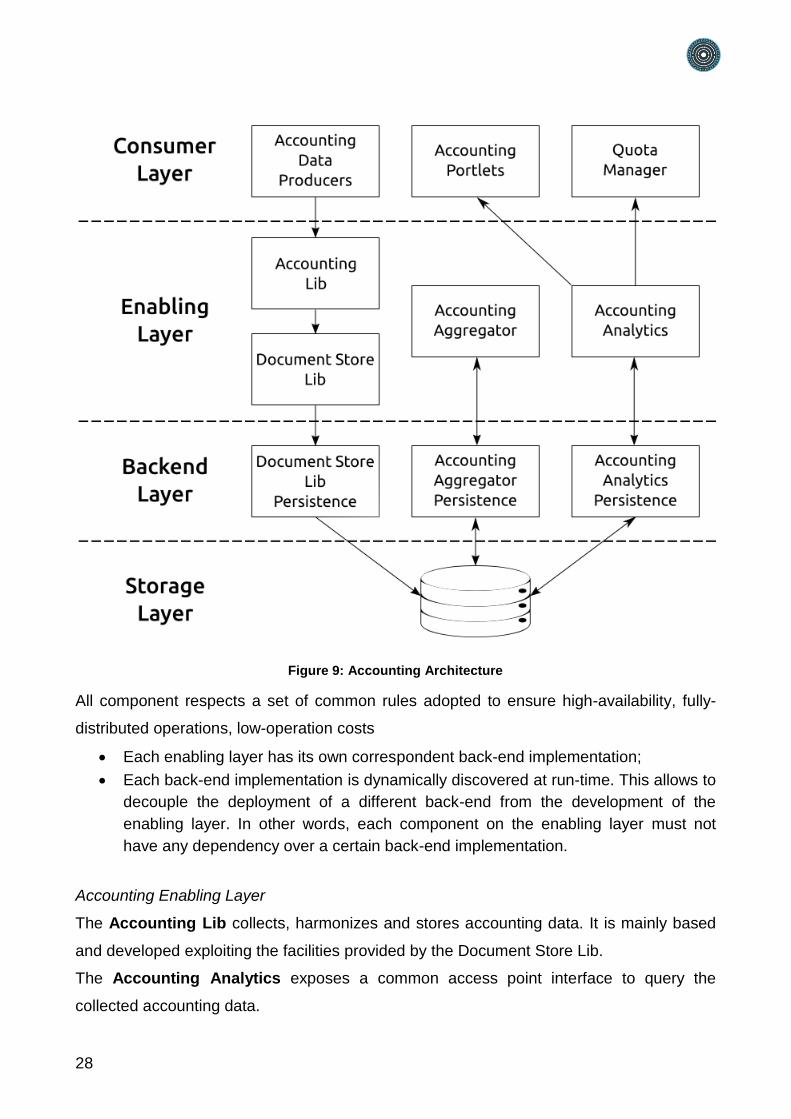
Architecture
The gCube Accounting architecture is logically divided in four different layers:
Accounting Consumer Layer
Accounting Enabling layer
Accounting Backend layer
Accounting Storage layer
28
Figure 9: Accounting Architecture
All component respects a set of common rules adopted to ensure high-availability, fully-
distributed operations, low-operation costs
Each enabling layer has its own correspondent back-end implementation;
Each back-end implementation is dynamically discovered at run-time. This allows to
decouple the deployment of a different back-end from the development of the
enabling layer. In other words, each component on the enabling layer must not
have any dependency over a certain back-end implementation.
Accounting Enabling Layer
The Accounting Lib collects, harmonizes and stores accounting data. It is mainly based
and developed exploiting the facilities provided by the Document Store Lib.
The Accounting Analytics exposes a common access point interface to query the
collected accounting data.
PARTHENOS – D6.1
29
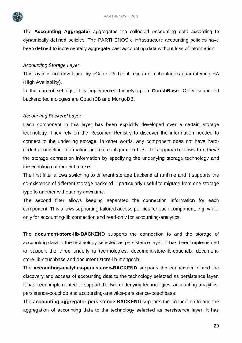
The Accounting Aggregator aggregates the collected Accounting data according to
dynamically defined policies. The PARTHENOS e-infrastructure accounting policies have
been defined to incrementally aggregate past accounting data without loss of information
Accounting Storage Layer
This layer is not developed by gCube. Rather it relies on technologies guaranteeing HA
(High Availability).
In the current settings, it is implemented by relying on CouchBase. Other supported
backend technologies are CouchDB and MongoDB.
Accounting Backend Layer
Each component in this layer has been explicitly developed over a certain storage
technology. They rely on the Resource Registry to discover the information needed to
connect to the underling storage. In other words, any component does not have hard-
coded connection information or local configuration files. This approach allows to retrieve
the storage connection information by specifying the underlying storage technology and
the enabling component to use.
The first filter allows switching to different storage backend at runtime and it supports the
co-existence of different storage backend – particularly useful to migrate from one storage
type to another without any downtime.
The second filter allows keeping separated the connection information for each
component. This allows supporting tailored access policies for each component, e.g. write-
only for accounting-lib connection and read-only for accounting-analytics.
The document-store-lib-BACKEND supports the connection to and the storage of
accounting data to the technology selected as persistence layer. It has been implemented
to support the three underlying technologies: document-store-lib-couchdb, document-
store-lib-couchbase and document-store-lib-mongodb;
The accounting-analytics-persistence-BACKEND supports the connection to and the
discovery and access of accounting data to the technology selected as persistence layer.
It has been implemented to support the two underlying technologies: accounting-analytics-
persistence-couchdb and accounting-analytics-persistence-couchbase;
The accounting-aggregator-persistence-BACKEND supports the connection to and the
aggregation of accounting data to the technology selected as persistence layer. It has
30
been implemented to support the two underlying technologies: accounting-aggregator-
persistence-couchdb and accounting-aggregator-persistence-couchbase;
Accounting Consumer Layer
Each component in this layer allows either producing or consuming accounting
information. It does not include only a graphical interface designed for managers, i.e.
Accounting Portlet. Rather it includes all the components that collect accounting data as
the Quota Manager, currently in development stage.
2.3. Storage Framework
2.3.1. Overview
The Storage framework is realized by a combination of services and libraries powered by
the gCube System open-source project. It is composed by three main systems: File-Based
System, Metadata Store System, and Spatial Data Repository System. These acts as
main driver for clients that interface the storage resources managed by the system or
accessible through facilities available within the system.
The File-Based System supports functions for standards-based and structured access
and storage of files of arbitrary size.
The Metadata Store System supports functions for the storage of metadata objects in
XML format.
The Spatial Data Repository System is composed by a number of different spatial data
repositories for storing spatial data in different (standard) formats (e.g. NetCDF, vector
data, raster data etc.)
2.3.2. Key Features
Standards compliancy Support for standard communication protocols /
interfaces and data / metadata formats.
Economy of scale Services constituting one aggregative infrastructure
may be hosted over servers maintained at different
sites
Failover Management Automatically transfers control to a duplicate
computational node when faults or failures are detected
Support of geospatial dataset Support for generation, revision, publishing, access,
PARTHENOS – D6.1
31
lifecycle visualization and sharing of geospatial data.
Support for analysis and processing Support for high performance operations over datasets
Geo-referencing datasets Provide analysis tools to create standard spatial
representation of datasets
2.3.3. Subsystems
2.3.3.1. File-Based Store System
The File-Based Store system includes services providing clients functions for standards-
based and structured access and storage of files of arbitrary size. This is a fundamental
requirement for a wide range of system processes, including indexing, transfer,
transformation, and presentation. Equally, it is a main driver for clients that interface the
resources managed by the PARTHENOS infrastructure or accessible through facilities
available within the same infrastructure.
The File-Based System is composed by a service abstracting over the physical storage
and capable of mounting several different store implementations, (by default clients can
make use of the MongoDB store) presenting a unified interface to the clients and allowing
them to download, upload, remove, add and list files or unstructured byte-streams (binary
objects). The binary objects must have owners and owners may define access rights to
files, allowing private, public, or shared (group-based) access.
All the operations of this service are provided through a standards-based, POSIX-like API
which supports the organization and operations normally associated with local file systems
whilst offering scalable and fault-tolerant remote storage
32
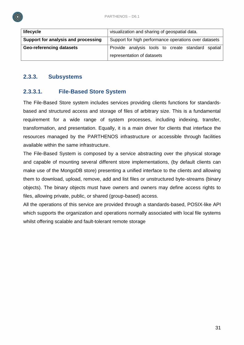
Figure 10: File-Based System Architecture
As shown in Figure 10: File-Based System Architecture the core of the Storage Manager
service is a software component named Storage Manager Core that offers APIs allowing
to abstracts over the physical storage. The Storage Manager Wrapper instead is a
software component used to discover back-end information from the Resource Registry
service of the PARTHENOS Infrastructure. The separation between these two
components is necessary to allow the usage of the service in different contexts other than
the PARTHENOS Infrastructure.
2.3.3.2. Metadata Store System
The Metadata Store system includes services for the storage of metadata objects in XML
format. The core service is the MDStore Sevice, a web service that implements the factory
pattern for the management of MDStore units.
An MDStore unit is a metadata store capable of storing metadata objects of a given
metadata data model. Consumers can create and delete units, and add, remove, update,
fetch, get statistics on metadata objects from-to a given unit via the MDStore Service. The
Service is implemented as an abstraction over the document-oriented storage MongoDB in
order to exploit its high-scalability and replica management features, but also to take
PARTHENOS – D6.1
33
advantage of out-of-the-box support with the Hadoop Map-Reduce framework, if
necessary.
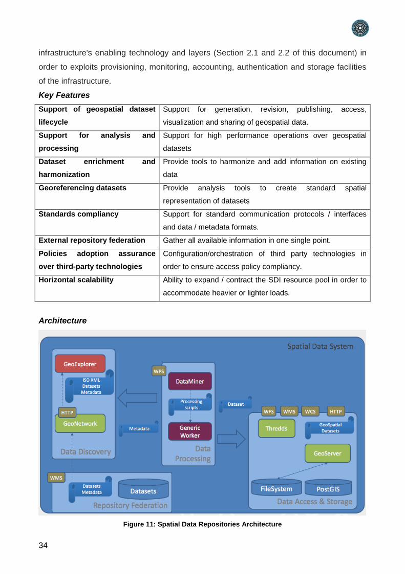
2.3.3.3. Spatial Data Repositories
The Spatial Data Repositories include services, technology, policies and practices
designed in order to provide the following features:
Data Discovery: The ability to browse, query and access metadata files about
accessible geospatial datasets. This feature is obtained exploiting GeoNetwork
webservice, the Open Source catalogue for geospatial metadata compliant with
standards mandated by Open Geospatial Consortium (OGC).
External Repository Federation: Transparently extend the Data Discovery
capabilities by including output from registered external catalogues and repositories
in order to give users global result from a single point.
Data Access & Storage: Provide users and applications to access/store geospatial
data in standard formats. Due to the heterogeneity of spatial data representation
and formats, the following technologies have been adopted:
◦ PostGIS: Geospatial extension of PostgreSQL relational DBMS;
◦ GeoServer: Open Source application for management and dissemination of
geospatial data through standards mandated by OGC;
◦ Thredds Data Server: Unidata's Thematic Real-time Environmental Distributed
Data Services (THREDDS) is a web server that provides data access for
scientific geospatial dataset formats (i.e. NetCDF).
Data Processing: The Data Processing framework includes services designed to
perform analysis and transformations over geospatial datasets. The adoption of
52°North Web Processing Service (WPS) grants users a standardized way to
interact with Data Processing facilities. This framework is fully described in section
2.4 of this document.
Data Visualization: Web application, named GeoExplorer, designed to render
views of overlapped geospatial datasets on a specific Earth projection, with the
ability to query / inspect and export selected data and rendered images.
The set of spatial data repositories and the comprehensive set of integrated technologies
for their management, discovery, and exploitation is fully integrated with both
34
infrastructure's enabling technology and layers (Section 2.1 and 2.2 of this document) in
order to exploits provisioning, monitoring, accounting, authentication and storage facilities
of the infrastructure.
Key Features
Support of geospatial dataset
lifecycle
Support for generation, revision, publishing, access,
visualization and sharing of geospatial data.
Support for analysis and
processing
Support for high performance operations over geospatial
datasets
Dataset enrichment and
harmonization
Provide tools to harmonize and add information on existing
data
Georeferencing datasets Provide analysis tools to create standard spatial
representation of datasets
Standards compliancy Support for standard communication protocols / interfaces
and data / metadata formats.
External repository federation Gather all available information in one single point.
Policies adoption assurance
over third-party technologies
Configuration/orchestration of third party technologies in
order to ensure access policy compliancy.
Horizontal scalability Ability to expand / contract the SDI resource pool in order to
accommodate heavier or lighter loads.
Architecture
Figure 11: Spatial Data Repositories Architecture
PARTHENOS – D6.1
35
The set of Spatial Data Repositories technologies selected and integrated are not only
fully compliant with the Open Geospatial Consortium (OGC) standards, i.e. Web Map
Service (WMS), Web Coverage Service (WCS), and Web Feature Service (WFS). Rather
specific mediators and validators have been designed and implemented to respect the
INSPIRE Directive, the EU initiative geared to help to make spatial or geographical
information more accessible and interoperable for a wide range of purposes supporting
sustainable development.
The Data Discovery components allow the discovery at runtime of all available datasets
independently of their locations and it is indifferent to the technology used to host them. It
also indifferent to the fact that the data are maintained by a repository managed by the
PARTHENOS Cloud Infrastructure or by an independent provider. The same applies also
to the Data Processing components that first discover the datasets to process and then
are able to process them independently of the technology used to host them and the
provider entitled to manage them.
2.4. Analytics Framework
2.4.1. Overview
The Analytics Framework includes a set of features, services and methods for performing
data processing and mining on information sets. These features face several aspects of
data processing ranging from modeling to clustering, from identification of anomalies to
detection of hidden series. This set of services and libraries is used by the e-infrastructure
to manage data mining problems even from a computational complexity point of view.
Algorithms are executed in parallel and possibly distributed fashion, using the same e-
infrastructure nodes as working nodes. Furthermore, Services performing Data Mining
operations are deployed according to a distributed architecture, in order to balance the
load of those procedures requiring local resources.
2.4.2. Key Features
Parallel Processing Support for the execution of algorithms on multi-cores
computational nodes
Distributed Processing Transparent distribution of the execution on sets of
computational nodes
Failover Management Automatically transfers control to a duplicate computational
36
node when faults or failures are detected
State-of-the-art data mining
algorithms
General purpose algorithms (e.g. Clustering, Principal
Component Analysis, Artificial Neural Networks, Maximum
Entropy, etc.) supplied as-a-service
Data trends generation and
analysis
Identification of trends; inspection of time series to
automatically identify anomalies; basic signal processing
techniques to explore periodicities in trends
2.4.3. Subsystems
2.4.3.1. Data Miner System
The Data Miner System’s goal is to offer a unique access for performing data mining or
statistical operations on heterogeneous data. These data can reside on the client side in
the form of CSV files or they can be remotely hosted, as SDMX documents or,
furthermore, they can be stored in a database.
The Data Miner System is composed by a service, namely Data Miner service, able to take
such inputs and execute the operation requested by a client interface, by invoking the
most suited computational infrastructure, choosing among a set of available possibilities:
executions can run on multi-core machines, or on different computational infrastructures,
like the PARTHENOS, Windows Azure, CompSs and other options.
Algorithms are implemented as plug-ins which makes the injection mechanism of new
functionalities easy to deploy.
Key Features
Openness Interaction with external software supporting Standard
protocols
Parallel Processing Support for the execution of algorithms on multi-cores
computational nodes
Distributed Processing Transparent distribution of the execution on sets of
computational nodes
State-of-the-art data mining
algorithms
General purpose algorithms (e.g. Clustering, Principal
Component Analysis, Artificial Neural Networks, Maximum
Entropy, etc.) supplied as-a-service
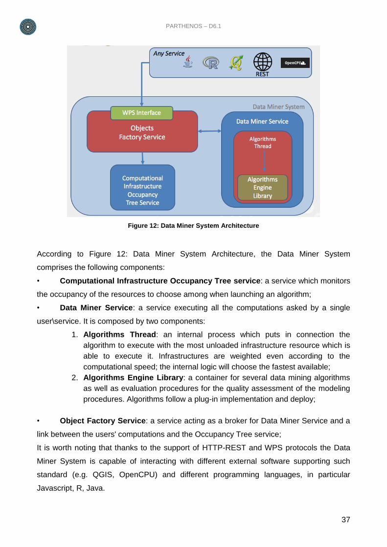
Architecture
PARTHENOS – D6.1
37
Figure 12: Data Miner System Architecture
According to Figure 12: Data Miner System Architecture, the Data Miner System
comprises the following components:
• Computational Infrastructure Occupancy Tree service: a service which monitors
the occupancy of the resources to choose among when launching an algorithm;
• Data Miner Service: a service executing all the computations asked by a single
user\service. It is composed by two components:
1. Algorithms Thread: an internal process which puts in connection the
algorithm to execute with the most unloaded infrastructure resource which is
able to execute it. Infrastructures are weighted even according to the
computational speed; the internal logic will choose the fastest available;
2. Algorithms Engine Library: a container for several data mining algorithms
as well as evaluation procedures for the quality assessment of the modeling
procedures. Algorithms follow a plug-in implementation and deploy;
• Object Factory Service: a service acting as a broker for Data Miner Service and a
link between the users' computations and the Occupancy Tree service;
It is worth noting that thanks to the support of HTTP-REST and WPS protocols the Data
Miner System is capable of interacting with different external software supporting such
standard (e.g. QGIS, OpenCPU) and different programming languages, in particular
Javascript, R, Java.
38
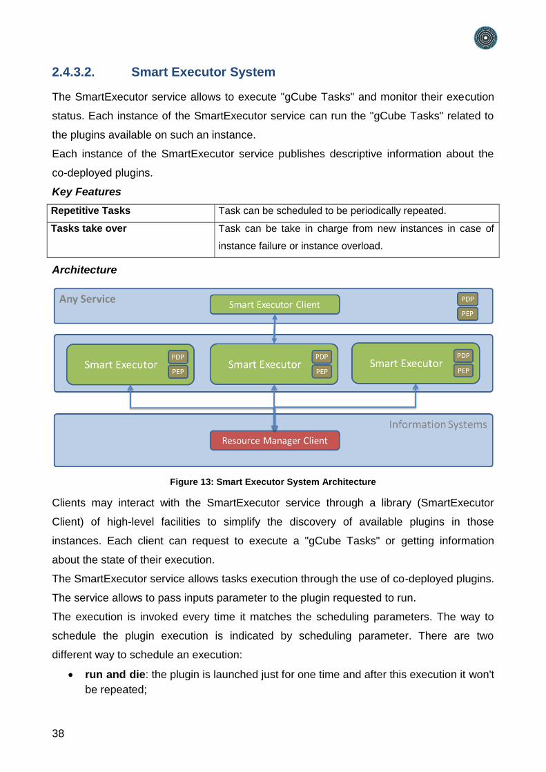
2.4.3.2. Smart Executor System
The SmartExecutor service allows to execute "gCube Tasks" and monitor their execution
status. Each instance of the SmartExecutor service can run the "gCube Tasks" related to
the plugins available on such an instance.
Each instance of the SmartExecutor service publishes descriptive information about the
co-deployed plugins.
Key Features
Repetitive Tasks Task can be scheduled to be periodically repeated.
Tasks take over Task can be take in charge from new instances in case of
instance failure or instance overload.
Architecture
Figure 13: Smart Executor System Architecture
Clients may interact with the SmartExecutor service through a library (SmartExecutor
Client) of high-level facilities to simplify the discovery of available plugins in those
instances. Each client can request to execute a "gCube Tasks" or getting information
about the state of their execution.
The SmartExecutor service allows tasks execution through the use of co-deployed plugins.
The service allows to pass inputs parameter to the plugin requested to run.
The execution is invoked every time it matches the scheduling parameters. The way to
schedule the plugin execution is indicated by scheduling parameter. There are two
different way to schedule an execution:
run and die: the plugin is launched just for one time and after this execution it won't
be repeated;
PARTHENOS – D6.1
39
scheduled: the plugin repeat its execution over time according to a delay interval or
to a “cron” expression.
SmartExecutor instances could take care of a scheduled run when the node where it was
previously allocated crashes or is overloaded. To achieve this goal a scheduled task
description is registered in the Information System through the Resource Manager.
2.5. Content Cloud Framework
2.5.1. Overview
The PARTHENOS Content Cloud is a digital space that acts as container of resources and
metadata of resources aggregated from RI registries registered in the PARTHENOS
registry.
The Content Cloud Framework (CCF) groups the services needed to (i) populate the
Content Cloud, and (ii) make the Content Cloud accessible to human and machines
according to different standard protocols.
The CCF is based on the D-Net Software toolkit, a service-oriented framework specifically
designed to support developers at constructing custom aggregative infrastructures in a
cost-effective way.
The D-Net Software Toolkit is open source (Apache license), fully developed in Java,
based on the Web Service framework (http://www.w3.org/2002/ws), and available for
download at http://www.d-net.research-infrastructures.eu. Its first software release was
designed and developed within the DRIVER and DRIVER-II EC projects (2006-2008)
(Feijen et al., 2007). The scenario motivating its realization was that of constructing the
European repository infrastructure for Open Access repositories. The infrastructure had to
harvest (tens of) millions of Dublin Core metadata records from hundreds of OAI-PMH
repository data sources, harmonize the structure and values of such records to form a
uniform information space.
A D-NET data infrastructure is a run-time distributed environment, inspired by Service-
Oriented Architecture paradigms (Lomow and Newcomer, 2005; MacKenzie et al., 2006),
where administrators can dynamically construct, refine, and monitor aggregation and data
management workflows for information space construction.
40
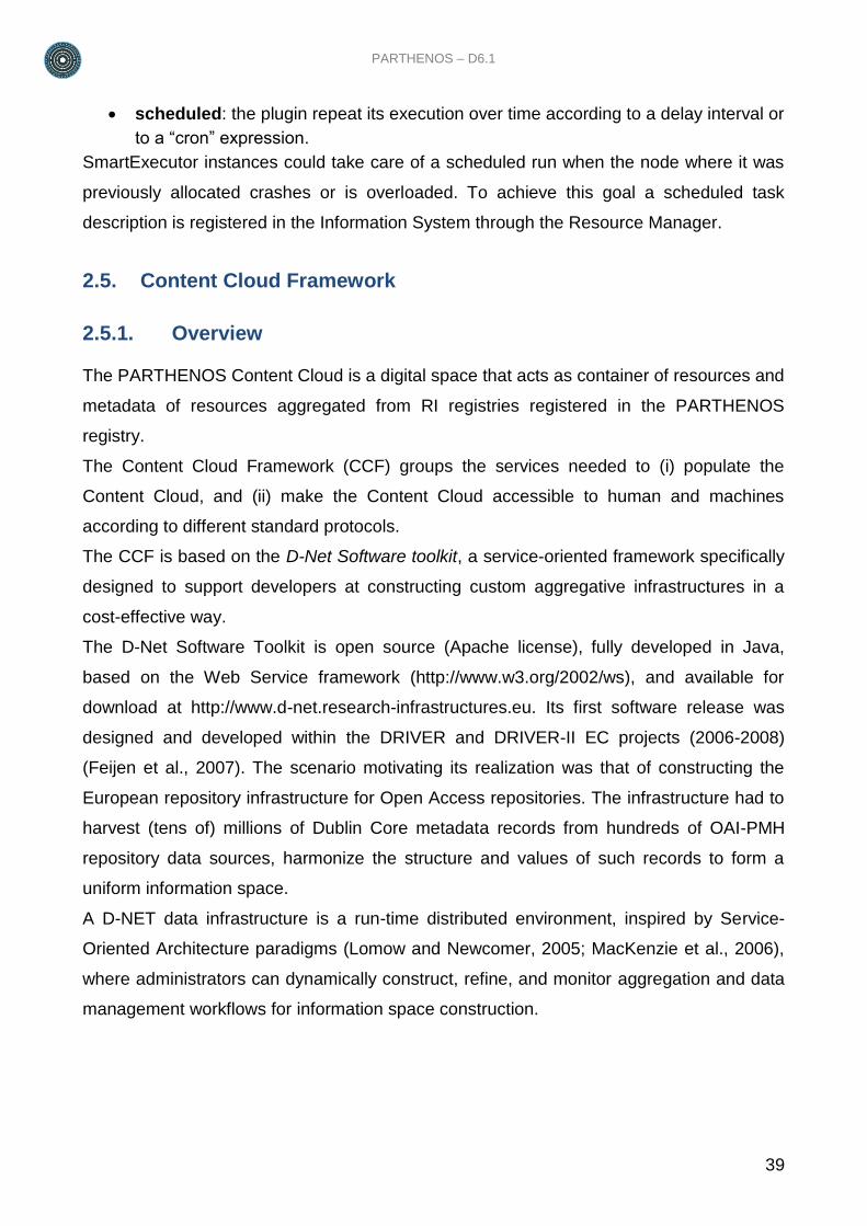
Figure 14: D-NET Aggregative Infrastructure Architecture
2.5.2. Key Features
Economy of scale Services constituting one aggregative infrastructure may be
hosted over servers maintained at different sites
Robustness Service replicas, i.e. clones of functionality and content, can
be kept at different sites. This strategy, in combination with
dynamic discovery of resources, makes the system more
robust to network failures and system crashes (availability of
service) as well as to concurrent accesses (scalability by
PARTHENOS – D6.1
41
workload distribution).
Autonomicity Manager Services can autonomously orchestrate and
monitor the status of services in the aggregative
infrastructure
Elasticity Thanks to dynamic discovery, services can join or leave the
infrastructure anytime without administrators having to re-
configure application workflows.
Modularity Services provide “functionality in isolation”, that is
functionality “factored out as much as possible”, in order to
maximize re-use in different workflows
Customizability Services managing metadata objects should be customizable
at run-time to operate according to a given data model. This
feature makes service instances dynamically programmable
and promotes their re-use to serve different goals
Metadata Interoperability Services are able to manage metadata records in different
formats. Different standard exchange protocols are
supported both in import and export phases. In the import
phase (data collection) idiosyncratic protocols can also be
supported by integrating dedicated plugins.
2.5.3. Subsystems
The Content Cloud Framework (CCF) is an instance of D-NET configured for
PARTHENOS. Thanks to the D-Net modularity, the CCF can be constructed by selecting
and configuring the D-NET sub-systems and services that are needed to satisfy the
requirements of PARTHENOS among those available in Figure 14, namely:
Workflow Manager and Orchestration System: for the execution of aggregation
workflows in autonomicity;
Data Source Management System: for the management of dynamic data sources
(i.e. data sources that can join/leave the infrastructure at run-time);
Data Collection System: services to collect metadata and resources according to
different models, formats via different exchange protocols;
Data Transformation System: services to transform metadata from an original
model to the Parthenos data model;
Data Provision System: services that interface external applications, e.g. end-user
portals, third-party services, with resources and metadata in the Content Cloud.
42
2.5.3.1. Workflow Management System
The Workflow Manager and Orchestration System (MS) addresses service orchestration
and monitoring, hence “autonomic behavior”. One or more MSs can be configured by
developers to autonomously execute workflows. D-NET workflows are resources
describing sequences of steps, where each step may consist of business logic (i.e. Java
code), remote service invocations, workflow forks (i.e. parallel sub-workflows), and
workflow conjunctions (confluence of parallel workflows). Typically, service invocations are
preceded by a look-up into the IS, which discovers the “best” service of the needed kind
and available to execute the call. Workflows can be fired manually or as a consequence of
the notification of a resource-related event from the IS or because of time-events, i.e. cron
jobs. Workflows are commonly used to automatically schedule data collection from data
sources and population of information spaces.
Workflows can implement long-term transactions by exploiting subscription and notification
of events in the IS. When a time-consuming step is to be fired (e.g. indexing a large set of
metadata objects), the invocation is accompanied by a subscription request to the event
“conclusion of the step”. The MS waits for the relative notification before moving on to the
next step. Workflows can also be used as monitoring threads, checking for consistency
and availability of resources or consistency and Quality of Service of the aggregative
infrastructure. For example, aggregative infrastructure policies may require that a given
collection of information objects be replicated K times; monitoring workflows may, at given
time intervals, check that this is really the case and possibly take corrective actions, e.g.
creating a missing replica. When corrective actions are not possible, warning emails can
be sent to administrators.
The MS user interface offers a graphical overview of the ongoing workflows and allows
administrators to interact with such workflows, for example to manually re-execute them or
to redefine their configuration parameters. In the current D-NET implementation, workflows
are not treated as infrastructure resources, i.e. cannot be shared by different instances of
the Manager Service, and are preserved in the local status of the service.
2.5.3.2. Data Source Management System
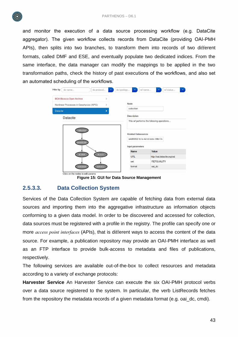
The Data Source Management System provides services and graphical user interfaces
(GUIs) for the registration and administration of data sources to the aggregative
infrastructure, meaning the organization and scheduling of the respective data collection
and processing workflows. Figure 15 illustrates the admin user interface used to execute
PARTHENOS – D6.1
43
and monitor the execution of a data source processing workflow (e.g. DataCite
aggregator). The given workflow collects records from DataCite (providing OAI-PMH
APIs), then splits into two branches, to transform them into records of two different
formats, called DMF and ESE, and eventually populate two dedicated indices. From the
same interface, the data manager can modify the mappings to be applied in the two
transformation paths, check the history of past executions of the workflows, and also set
an automated scheduling of the workflows.
Figure 15: GUI for Data Source Management
2.5.3.3. Data Collection System
Services of the Data Collection System are capable of fetching data from external data
sources and importing them into the aggregative infrastructure as information objects
conforming to a given data model. In order to be discovered and accessed for collection,
data sources must be registered with a profile in the registry. The profile can specify one or
more access point interfaces (APIs), that is different ways to access the content of the data
source. For example, a publication repository may provide an OAI-PMH interface as well
as an FTP interface to provide bulk-access to metadata and files of publications,
respectively.
The following services are available out-of-the-box to collect resources and metadata
according to a variety of exchange protocols:
Harvester Service An Harvester Service can execute the six OAI-PMH protocol verbs
over a data source registered to the system. In particular, the verb ListRecords fetches
from the repository the metadata records of a given metadata format (e.g. oai_dc, cmdi).
44
File Download Service A File Downloader Service can download into a given Store unit a
set of files whose URLs are provided as input. Additional plug-in are available to fetch the
download URL from metadata records already collected by the aggregator.
FTP Service An FTP Service can download files from a given FTP data source registered
to the system.
HTTP Service HTTP access points are remote calls, which follow a site-dependent URL
syntax and return site-dependent HTML/XML/CSV lists of results; e.g. a search on a
website index. The HTTP Service is an executor of “HTTP connector modules”. Each
module, which is identified by a unique name, a URL, a list of parameters and an output
metadata data model resource, is implemented by code capable of performing the HTTP
calls properly using the parameters. Data source resources can, in their profile, specify an
HTTP access point by indicating the name of the module to be used. It is often the case
that the same module can be re-used to access content from several data sources, which
are possibly based on the same technology. On the other hand, when this is not the case,
the implementation of the import code is strictly limited to access to the specific data
source.
2.5.3.4. Data Transformation System
The Data Transformation System leverages services for transforming metadata objects of
one metadata data model into objects of one output metadata data model (Haslhofer and
Klas, 2010). User interfaces allow data managers to specify the logic of the transformation,
i.e. the mapping, which can be an XSLT, a D-Net script or an X3M mapping file generated
with the X3M Mapping tool implemented by the project partner FORTH and available in the
PARTHENOS infrastructure.
In the specific case of PARTHENOS, it is expected that mappings will be prepared with the
X3M Mapping tool and registered in the registry in order to be discoverable by the D-Net
Data Transformation System.
2.5.3.5. Data Provision System
Services in the data provision area interface external applications, e.g. end-user portals,
third-party services, with resources and metadata in the Content Cloud in its different
manifestations. Specifically, metadata are made available to third-parties via the following
services:
PARTHENOS – D6.1
45
OAI-PMH Publisher Service An OAI-PMH Publisher Service offers OAI- PMH interfaces
to third-party applications (i.e. harvesters) willing to access metadata objects. The service
can be dynamically configured to expose sets grouping records that satisfy given criteria
(e.g. original data source, value of the subject field). The service is implemented on
MongoDB.
Index and Browse Service An Index (factory) Service manages a set of Index units
capable of indexing metadata objects of a given data model. Consumers can feed units
with metadata objects, remove objects or query the records. As indexing back-end, the
service supports Apache Solr (Kuć, 2013), a de-facto standard for full-text indexing and
content retrieval. The schema of the Solr index will be configured by the Index Service
according to a configuration, that can be changed dynamically at run-time, in terms of
indexable and browsable fields. The Solr index offers built-in REST APIs that can be used
by third-parties to query and browse by faceted search the PARTHENOS Content Cloud.
2.6. Collaborative Framework
2.6.1. Overview
The Collaborative Framework is realized through a combination of software components
(services and libraries) powered by the gCube System. Three main subsystems
characterise the Collaborative Framework:
Social Networking System
Shared workspace System
User Management System
These systems provide consumers with a homogenous abstraction layer over different
external technologies enabling to operation of the framework. The external technologies
involved comprises, Apache Cassandra, Apache Jackrabbit, Elastic Search, MongoDB,
and Liferay Portal. In particular, the Social Networking System exploits an Apache
Cassandra cluster and an Elastic Search cluster, the Shared Workspace System exploits
an Apache Jackrabbit repository (metadata) and a MongoDB cluster (payload) for its
backend, the User Management System exploits Liferay Portal for its backend and to allow
users to login for personalized services or views.
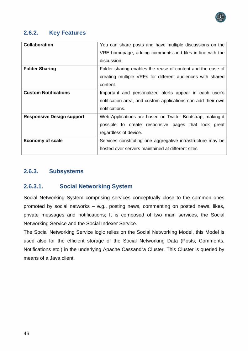
46
2.6.2. Key Features
Collaboration You can share posts and have multiple discussions on the
VRE homepage, adding comments and files in line with the
discussion.
Folder Sharing Folder sharing enables the reuse of content and the ease of
creating multiple VREs for different audiences with shared
content.
Custom Notifications Important and personalized alerts appear in each user’s
notification area, and custom applications can add their own
notifications.
Responsive Design support Web Applications are based on Twitter Bootstrap, making it
possible to create responsive pages that look great
regardless of device.
Economy of scale Services constituting one aggregative infrastructure may be
hosted over servers maintained at different sites
2.6.3. Subsystems
2.6.3.1. Social Networking System
Social Networking System comprising services conceptually close to the common ones
promoted by social networks – e.g., posting news, commenting on posted news, likes,
private messages and notifications; It is composed of two main services, the Social
Networking Service and the Social Indexer Service.
The Social Networking Service logic relies on the Social Networking Model, this Model is
used also for the efficient storage of the Social Networking Data (Posts, Comments,
Notifications etc.) in the underlying Apache Cassandra Cluster. This Cluster is queried by
means of a Java client.
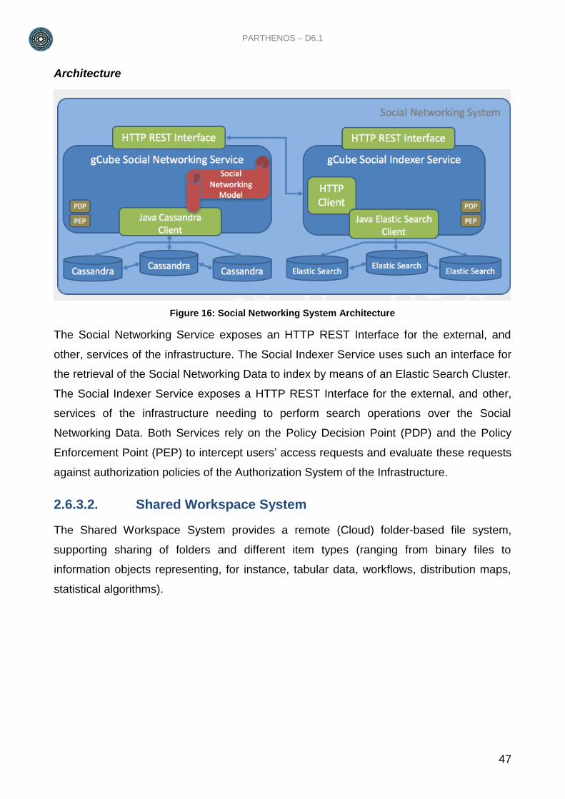
PARTHENOS – D6.1
47
Architecture
Figure 16: Social Networking System Architecture
The Social Networking Service exposes an HTTP REST Interface for the external, and
other, services of the infrastructure. The Social Indexer Service uses such an interface for
the retrieval of the Social Networking Data to index by means of an Elastic Search Cluster.
The Social Indexer Service exposes a HTTP REST Interface for the external, and other,
services of the infrastructure needing to perform search operations over the Social
Networking Data. Both Services rely on the Policy Decision Point (PDP) and the Policy
Enforcement Point (PEP) to intercept users’ access requests and evaluate these requests
against authorization policies of the Authorization System of the Infrastructure.
2.6.3.2. Shared Workspace System
The Shared Workspace System provides a remote (Cloud) folder-based file system,
supporting sharing of folders and different item types (ranging from binary files to
information objects representing, for instance, tabular data, workflows, distribution maps,
statistical algorithms).
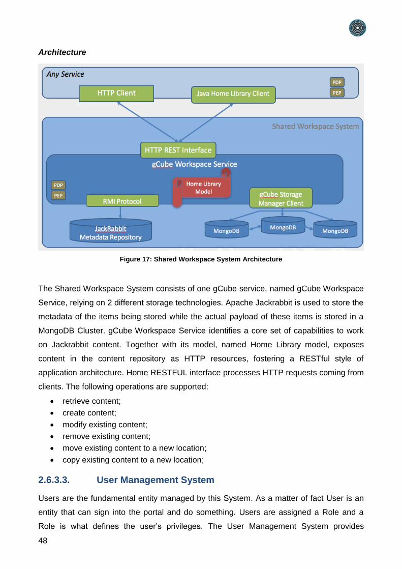
48
Architecture
Figure 17: Shared Workspace System Architecture
The Shared Workspace System consists of one gCube service, named gCube Workspace
Service, relying on 2 different storage technologies. Apache Jackrabbit is used to store the
metadata of the items being stored while the actual payload of these items is stored in a
MongoDB Cluster. gCube Workspace Service identifies a core set of capabilities to work
on Jackrabbit content. Together with its model, named Home Library model, exposes
content in the content repository as HTTP resources, fostering a RESTful style of
application architecture. Home RESTFUL interface processes HTTP requests coming from
clients. The following operations are supported:
retrieve content;
create content;
modify existing content;
remove existing content;
move existing content to a new location;
copy existing content to a new location;
2.6.3.3. User Management System
Users are the fundamental entity managed by this System. As a matter of fact User is an
entity that can sign into the portal and do something. Users are assigned a Role and a
Role is what defines the user’s privileges. The User Management System provides

PARTHENOS – D6.1
49
functionality to manage personal profiles and users in the PARTHENOS infrastructure,
supporting user groups (for the purpose of group specific privileges) and roles for
application specific needs related to the user’s role in PARTHENOS.
50
3. Conclusions
The PARTHENOS e-infrastructure features a non-trivial architecture, supported by Cloud-
oriented resource provision (computation and storage) and enacted by service workflows
supporting scientists with an Information Cloud, with relative analytics and VRE-oriented
collaborative functionalities.
The resulting software can be deployed as a production service due to the adoption of
stable and supported software packages and past experience of the supporting
development teams. Specifically, OpenStack is adopted for cloud resource provision, D-
NET for the Information Cloud, and gCube for the analytics and collaborative framework
part.
The relative e-infrastructure system can be operated by keeping maintenance, refinement,
and extension costs at minimum since gCube and D-NET are devised according to
service-computing and loosely coupled components principles.