Embed Size (px)
Citation preview

PART TMMATERIAL REQUIREMENTS
Article TM-1Material Requirements
TM-100 GENERAL
The requirements of Part TM are applicable to allpressure parts in pressure vessels and attachments topressure parts, except as permitted by the applicableModal Appendix, and shall be used in conjunction withthe specific requirements given elsewhere in this Sectionthat pertain to the method of fabrication, the materialused, and the commodities being transported. See theapplicable Modal Appendix for materials for other partsof transport tanks.
TM-110 GENERAL REQUIREMENTS FOR ALLPRODUCTS
(a) Material subject to stress due to pressure, andattachments that are essential to structural integrity ofthe pressure vessel when welded to pressure-retainingcomponents, shall conform to one of the specificationsgiven in Tables TM-130.2-1 through TM-130.2-7 andlisted in Section II, Parts A and B, except as otherwisepermitted in TM-110.5, TM-110.10, TM-120, and TM-130.1. Material may be identified as meeting more thanone material specification or grade, provided the mate-rial meets all requirements of the identified materialspecification(s) or grade(s).
(b) Except as limited by TM-180.2, material for non-pressure parts, such as baffles, extended heat transfersurfaces, insulation supports, and minor attachments1
(such as clips, locating lugs, name plates) need not con-form to the specifications for the material to which theyare attached or to a material specification permitted inthis Section; but if attached to the vessel by welding, itshall be of weldable quality. The allowable stress valuesfor material not identified in accordance with TablesTM-130.2-1 through TM-130.2-7 shall not exceed 80%of the maximum allowable stress value permitted forsimilar material in Tables TM-130.2-1 to TM-130.2-7.
(c) Materials other than those allowed by this Sectionmay not be used, unless data thereon are submitted to
1 Minor attachments are parts of small size [not over 10 mm(3⁄8 in.) thick or 80 cm3 (5 in.3) volume] that support no load orinsignificant load.
9
and approved by the Boiler and Pressure Vessel Commit-tee in accordance with Appendix 5 in Section II, Part D.
(d) Materials outside the limits of size and/or thick-ness listed in the title or scope clause of the specificationslisted in Tables TM-130.2-1 through TM-130.2-7, and per-mitted elsewhere in this section, may be used if thematerial is in compliance with the other requirementsof the specification and no size or thickness limitationis given in the stress tables. In those specifications inwhich chemical composition or mechanical propertiesvary with size or thickness, materials outside the rangeshall be required to conform to the composition andmechanical properties shown for the nearest specifiedrange.
(e) All material used for construction of vessels andappurtenances must be suitable for the modal applica-tion and conditions specified by the User (see TG-310)and shall comply with the additional requirements inthe applicable Modal Appendices.
TM-110.1 Plates
Plates used in the construction of vessels shall con-form to one of the specifications in Tables TM-130.2-1through TM-130.2-7 for which allowable stress valuesare given in Section II, Part D, except as otherwise pro-vided in TM-110(a) through (e), TM-110.10, TM-120, andTM-130.1.
TM-110.2 Forgings
Forged material may be used in vessel construction,provided the material has been worked sufficiently toremove the coarse ingot structure. Specifications foracceptable forging materials are given in TablesTM-130.2-1 through TM-130.2-7 and maximum allow-able stress values in Section II, Part D.
TM-110.3 Castings
Cast material may be used in the construction of ves-sels and vessel parts. Specifications for acceptable cast-ing materials are listed in Tables TM-130.2-1 throughTM-130.2-7 and the maximum allowable stress valuesin Section II, Part D. Castings shall comply with theadditional requirements in TM-190. The allowable stress
Copyright ASME International Provided by IHS under license with ASME
Not for ResaleNo reproduction or networking permitted without license from IHS
--`,,```,,,,````-`-`,,`,,`,`,,`---

TM-110.3 TM-110.102004 SECTION XII
values shall be multiplied by the applicable casting qual-ity factor given in TM-190.
TM-110.4 Pipe and Tubes
Pipe and tubes of seamless or welded constructionconforming to one of the specifications given in TablesTM-130.2-1 through TM-130.2-7 may be used for shellsand other parts of transport tanks. Allowable stress val-ues for the materials used in pipe and tubes are givenin Section II, Part D.
TM-110.5 Welding Materials
Welding materials used for production shall complywith the requirements of this Section, Section IX, andthe applicable qualified welding procedure specifica-tion. When the welding materials comply with one ofthe specifications in Section II, Part C, the marking ortagging of the material, containers, or packages asrequired by the applicable Section II specification maybe accepted for identification in lieu of a Material TestReport or a Certificate of Compliance. When the weldingmaterials do not comply with one of the specificationsof Section II, the marking or tagging shall be identifiablewith the welding materials set forth in the welding pro-cedure specification and may be accepted in lieu of aMaterial Test Report or a Certificate of Compliance.
TM-110.6 Bolts and Studs
(a) Bolts and studs may be used for the attachmentof removable parts. Permissible specifications are listedin Tables TM-130.2-1 through TM-130.2-7. Nuts and boltsshall conform to the requirements of TM-110.6 and theadditional rules in TM-150.1, TM-150.5, or TM-160.1, asapplicable. The allowable stresses for bolting materialsare given in Section II, Part D, Table 3.
(b) Studs shall be threaded full length or shall bemachined down to the root diameter of the thread in theunthreaded portion, provided that the threaded portionsare at least 11⁄2 diameters in length. Studs greater thaneight diameters in length may have an unthreaded por-tion that has the nominal diameter of the thread, pro-vided the following requirements are met:
(1) the threaded portions shall be at least 11⁄2 diame-ters in length
(2) the stud shall be machined down to the rootdiameter of the thread for a minimum distance of 0.5diameters adjacent to the threaded portion
(3) a suitable transition shall be provided betweenthe root diameter and the unthreaded portion
(4) particular consideration shall be given to anydynamic loadings
TM-110.7 Nuts and Washers
(a) Nuts shall conform to the requirements in theapplicable paragraph elsewhere in this Code (see TM-150.1, TM-150.2, and TM-160.2). They shall engage thethreads for the full depth of the nut.
10
(b) The use of washers is optional. When used, theyshall be of wrought materials.
TM-110.8 Rods and Bars
Rod and bar stock may be used in the vessel construc-tion for pressure parts such as flange rings, stiffeningrings, frames for reinforced openings, stays and stay-bolts, and similar parts. Rod and bar materials shallconform to the requirements for bars or bolting in theapplicable section elsewhere in this Code (see TM-150.4).
TM-110.9 Ferritic Steels With Tensile PropertiesEnhanced by Heat Treatment
Except when specifically prohibited by Part TM (seeTM-180.2 and TW-130.7), steels listed in Table TM-130.2-6 may be used for the entire vessel or for individualcomponents that are joined to other Grades listed in thatTable or to other steels conforming to the specificationsin Tables TM-130.2-1 or TM-130.2-2. The maximumallowable stress values for the materials listed in TableTM-130.2-6 are given in Section II, Part D.
TM-110.10 Prefabricated or Preformed PressureParts
Prefabricated or preformed pressure parts for vesselsthat are subject to stress due to pressure and that arefurnished by other than the shop of the Manufacturerresponsible for the vessel to be marked with the Codesymbol shall conform to all applicable requirements ofthis Section as related to the vessel, including servicerestrictions applicable to the material, inspection in theshop of the parts Manufacturer, and the furnishing ofPartial Data Reports, except as permitted in TM-110.10(a), (b), and (c). When the prefabricated or pre-formed parts are furnished with a nameplate and thenameplate interferes with further fabrication or service,and where stamping on the material is prohibited, theManufacturer of the completed vessel, with the concur-rence of the Inspector, may remove the nameplate. Theremoval of the nameplate shall be noted in the“Remarks” section of the tank Manufacturer ’s DataReport. The nameplate shall be destroyed. The rules ofTM-110.10(a), (b), and (c) shall not be applied to quick-actuating closure.
(a) Cast, Forged, Rolled, or Die-Formed Standard Pres-sure Parts
(1) Pressure parts, such as pipe fittings, flanges,nozzles, welding necks, welding caps, manhole framesand covers, that are wholly formed by casting, forging,rolling, or die forming shall not require inspection, iden-tification in accordance with TM-140.1(a) or (b), or Par-tial Data Reports. Standard pressure parts, whichcomply with some ASME/ANSI standard, shall be madeof materials permitted by this Section or of materials
Copyright ASME International Provided by IHS under license with ASME
Not for ResaleNo reproduction or networking permitted without license from IHS
--`,,```,,,,````-`-`,,`,,`,`,,`---

TM-110.10 TM-110.10PART TM — MATERIAL REQUIREMENTS
specifically listed in an ASME/ANSI product standard2
listed elsewhere in this Section. Standard pressure parts,which comply with a Manufacturer’s standard, shall bemade of materials permitted by this Section. Parts madeto either an ASME/ANSI standard or Manufacturer’sstandard shall be marked with the name or trademarkof the parts Manufacturer and such other markings asare required by the standard. Such markings shall beconsidered as the parts Manufacturer’s certification thatthe product complies with the material specificationsand standards indicated and is suitable for service atthe rating indicated. The intent of this paragraph willhave been met if, in lieu of the detailed marking on thepart itself, the parts described herein have been markedin any permanent or temporary manner that will serveto identify the part with the parts Manufacturer’s writtenlisting of the particular items and such listings are avail-able for examination by the Inspector.
(2) Flanges and flanged fittings may be used at thepressure-temperature ratings specified in Table TG-130.Other pressure-temperature ratings may be used if theflange satisfies the requirements of TM-110.10(a)(1) and,using the specified gaskets and bolting, satisfies thedesign requirements of TD-500.
(3) Parts of small size falling within this categoryfor which it is difficult or impossible to obtain identifiedmaterial or which may be stocked and for which identifi-cation in accordance with TM-140.2 cannot be economi-cally obtained and are not customarily furnished, andwhich do not appreciably affect the safety of the vessel,may be used for relatively unimportant parts or partsstressed to not more than 50% of the stress value permit-ted by this Section, provided they are suitable for thepurpose intended and are acceptable to the Inspector.The Manufacturer of the vessel to be marked with theCode symbol shall verify that the part is suitable for thedesign conditions specified for the vessel in accordancewith the rules of this Section.
(b) Cast, Forged, Rolled, or Die-Formed Nonstandard Pres-sure Parts. Pressure parts such as shells, heads, remov-able doors, and pipes coils that are wholly formed bycasting, forging, rolling, or die forming may be suppliedbasically as materials. All such parts shall be made ofmaterials permitted under this Section and the Manufac-turer of the part shall furnish identification in accordancewith TM-140.2. Such parts shall be marked with thename or trademark of the parts Manufacturer and withsuch other markings as will serve to identify the particu-lar parts with accompanying material identification. TheManufacturer of the tank to be marked with the Codesymbol shall satisfy himself that the part is suitable forthe design conditions specified for the completed tank
2 These are pressure parts that comply with some ASME/ANSIproduct standard accepted by reference in TD-100.5. The ASME/ANSI product standard establishes the basis for pressure-tempera-ture rating and marking, unless modified in TD-100.5.
11
in accordance with the rules of this Section.(c) Welded Standard Pressure Parts for Use Other Than
the Shell or Heads of a Vessel. Pressure parts, such aswelded standard pipe fittings, welding caps, and flangesthat are fabricated by one of the welding processes recog-nized by this Section shall not require inspection, identi-fication in accordance with TM-140.1(a) or (b), or PartialData Reports, provided that:
(1) standard pressure parts that comply with someASME/ANSI product standard2 shall be made of materi-als permitted by this Section or of materials specificallylisted in an ASME/ANSI product standard listed else-where in this Section. Standard pressure parts, whichcomply with a Manufacturer’s standard, shall be madeof materials permitted by this Section.
(2) welding for pressure parts that comply with aManufacturer ’s standard3,4 shall comply with therequirements of Article TF-2. Welding for pressure parts,which comply with some ASME/ANSI product stan-dard shall comply with the requirements of Article TF-2, or with the welding requirements of SA-234, 5.2 and5.3. Markings, where applicable, or Certification by theparts Manufacturer where markings are not applicable,shall be accepted as evidence of compliance with theabove welding requirements. Such parts shall be markedas required by TM-110.10(a)(1).
Such parts shall be marked with the name or trade-mark of the parts Manufacturer and with such othermarkings as will serve to identify the materials of whichthe parts are made. Such markings shall be consideredas the parts Manufacturer’s certification that the productcomplies with TM-110.10(c)(1). A statement by the partsManufacturer that all welding complies with Coderequirements shall be accepted as evidence that theproduct complies with TM-110.10(c)(2).
(3) if radiography or postweld heat treatment isrequired by the rules of this Section, it may be performedeither in the plant of the parts Manufacturer or in theplant of the manufacturer of the tank to be marked withthe Code symbol.
If the radiographing is done under the control of theparts Manufacturer, the completed radiographs, prop-erly identified, with a radiographic inspection reportshall be forwarded to the tank Manufacturer and shallbe available to the Inspector.
3 These are pressure parts that comply with a parts Manufactur-er ’s standard, which defines the pressure-temperature ratingmarked on the the part and described in the parts Manufacturer’sliterature. The Manufacturer of the completed vessel shall satisfyhimself that the part is suitable for the design conditions of thecompleted vessel in accordance with the rules of this Section.
4 Pressure parts may be in accordance with ASME/ANSI productstandard not covered by footnote 1, but such parts shall satisfythe requirements applicable to a parts Manufacturer’s standardand footnote 2.
Copyright ASME International Provided by IHS under license with ASME
Not for ResaleNo reproduction or networking permitted without license from IHS
--`,,```,,,,````-`-`,,`,,`,`,,`---

TM-110.10 TM-1202004 SECTION XII
(4) if heat treatment is performed at the plant ofthe parts Manufacturer, certification by the parts Manu-facturer that such treatment was performed shall beaccepted as evidence of compliance with applicableCode paragraphs. This certification shall be available tothe Inspector.
(d) Parts furnished under the provisions of TM-110.10(a), (b), and (c) need not be manufactured by aCertificate of Authorization Holder.
TM-120 MATERIAL IDENTIFIED WITH ORPRODUCED TO A SPECIFICATION NOTPERMITTED BY THIS SECTION, ANDMATERIAL NOT FULLY IDENTIFIED
(a) Identified Material With Complete Certification Fromthe Material Manufacturer. Material identified with a spec-ification not permitted by this Section, or procured tochemical composition requirements, and identified to asingle production lot as required by a permitted specifi-cation may be accepted as satisfying the requirementsof a specification permitted by this Section, providedthe conditions set forth in TM-120(a)(1) or (a)(2) aresatisfied.
(1) Recertification by an Organization Other Than theVessel or Part Manufacturer
(a) All requirements, including but not limitedto, melting method, melting practice, deoxidization,quality, and heat treatment of the specification permittedby this Section, to which the material is to be recertified,have been demonstrated to have been met.
(b) A copy of the certification by the materialManufacturer of the chemical analysis required by thepermitted specification, with documentation showingthe requirements to which the material was producedand purchased, and which demonstrates that there isno conflict with the requirements of the permitted speci-fication, has been furnished to the vessel or part Manu-facturer.
(c) A certification that the material was manufac-tured and tested in accordance with the requirementsof the specification to which the material is recertified,excluding the specific marking requirements, has beenfurnished to the vessel or part Manufacturer, togetherwith copies of all documents and test reports pertinentto the demonstration of conformance to the require-ments of the permitted specification.
(d) The material and the Certificate of Compli-ance or the Material Test Report has been identified withthe designation of the specification to which the materialis recertified and with the notation “Certified perTM-120.”
(2) Recertification by the Vessel or Part Manufacturer(a) A copy of the certification by the material
Manufacturer of the chemical analysis required by thepermitted specification, with documentation showing
12
that the requirements to which the material was pro-duced and purchased is in compliance with the require-ments of the permitted specification, is available to theInspector.
(b) For applications in which the maximumallowable stresses are subject to a cautionary note, docu-mentation is available to the Inspector that establisheswhat deoxidization was performed during the materialmanufacture, to the degree necessary for the vessel orpart Manufacturer to make a decision with regard tothe cautionary note.
(c) Documentation is available to the Inspector,which demonstrates that the metallurgical structure,mechanical property, and hardness requirements of thepermitted specification have been met.
(d) For material recertified to a permitted specifi-cation that requires a fine austenitic grain size or thatrequires a fine-grain practice be used during melting,documentation is available to the Inspector, which dem-onstrates that the heat treatment requirements of thepermitted specification have been met or will be metduring fabrication.
(e) The material has marking, acceptable to theInspector, for identification to the documentation.
(f) When the conformance of the material withthe permitted specification has been established, thematerial has been marked as required by the permittedspecification.
(b) Material Identified to a Particular Production Lot asRequired by a Specification Permitted by This Section butWhich Cannot Be Qualified Under TM-120(a). Any materialidentified to a particular production lot as required bya specification permitted by this Section, but for whichthe documentation required in TM-120(a) is not avail-able, may be accepted as satisfying the requirements ofthe specification permitted by this Section, provided thatthe conditions set forth below are satisfied.
(1) Recertification by an Organization Other Than theVessel or Part Manufacturer. Not permitted.
(2) Recertification by the Vessel or Part Manufacturer(a) Chemical analyses are made on different
pieces from the lot to establish a mean analysis, whichis to be accepted as representative of the lot. The pieceschosen for analysis shall be selected at random from thelot. The number of pieces selected shall be at least 10%of the number of pieces in the lot, but not less thanthree. For lots of three pieces or less, each piece shall beanalyzed. Each individual analysis for an element shallconform to the limits for product analysis in the permit-ted specification, and the mean for each element shallconform to the heat analysis limits of that specification.Analyses need only be made for those elements requiredby the permitted specification. However, considerationshould be given to making analyses for elements notspecified in the specification but that would be deleteri-ous if present in excessive amounts.
Copyright ASME International Provided by IHS under license with ASME
Not for ResaleNo reproduction or networking permitted without license from IHS
--`,,```,,,,````-`-`,,`,,`,`,,`---

TM-120 TM-130.2PART TM — MATERIAL REQUIREMENTS
(b) Mechanical property tests are made in accor-dance with the requirements of the permitted specifica-tion, and the results of the tests conform to the specifiedrequirements.
(c) For applications in which the maximumallowable stresses are subject to a cautionary note, chem-ical analysis results are obtained, which are sufficientto establish what deoxidization was used during thematerial manufacture, to the degree necessary for mak-ing a decision with regard to the cautionary note.
(d) When the requirements of the permitted spec-ification include metallurgical structure requirements(i.e., fine austenitic grain size), tests are made and theresults are sufficient to establish that those requirementsof the specification have been met.
(e) When the requirements of the permitted spec-ification include heat treatment, the material is heattreated in accordance with those requirements, eitherprior to or during fabrication.
(f) When the conformance of the material withthe permitted specification has been established, thematerial has been marked as required by the permittedspecification.
(c) Material Not Fully Identified. Material that cannotbe qualified under the provisions of either TM-120(a) or(b), such as material not fully identified as requiredby the permitted specification or unidentified material,may be accepted as satisfying the requirements of aspecification permitted by this Section, provided thatthe conditions set forth below are satisfied.
(1) Qualification by an Organization Other Than theVessel or Part Manufacturer. Not permitted.
(2) Qualification by the Vessel or Part Manufacturer(a) Each piece is tested to show that it meets
the chemical composition for product analysis and themechanical property requirements of the permittedspecification. Chemical analyses need only be made forthose elements required by the permitted specification.However, consideration should be given to making anal-yses for elements not specified in the specification butwhich would be deleterious if present in excessiveamounts. For plates, when the direction of final rollingis not known, both a transverse and a longitudinal ten-sion test specimen shall be taken from each samplinglocation designated in the permitted specification. Theresults of both tests shall conform to the minimumrequirements of the specification, but the tensile strengthof only one of the two specimens need conform to themaximum requirement.
(b) The provisions of TM-120(b)(2)(c), (b)(2)(d),and (b)(2)(e) are met.
(c) When the identity of the material with thepermitted specification has been established in accor-dance with TM-120(c)(2)(a) and (c)(2)(b), each piece (orbundle, etc., if permitted in the specification) is marked
13
with a marking giving the permitted specification num-ber and grade, type, or class as applicable and a serialnumber identifying the particular lot of material. A suit-able report, clearly marked as being a “Report on Testsof Nonidentified Material,” shall be completed and certi-fied by the tank or part Manufacturer. This report, whenaccepted by the Inspector, shall constitute authority touse the material in lieu of material procured to therequirements of the permitted specification.
TM-130 MATERIAL SPECIFICATIONS
TM-130.1 Product Specification
When there is no material specification listed in TablesTM-130.2-1 through TM-130.2-7 covering a particularwrought product of a grade, but there is an approvedspecification listed in Tables TM-130.2-1 throughTM-130.2-7 covering some other wrought product of thatgrade, the product for which there is no specificationmay be used, provided:
(a) the chemical and mechanical properties, heattreating requirements, and requirements for deoxida-tion, or grain size requirements conform to the approvedspecification listed in Tables TM-130.2-1 throughTM-130.2-7. The stress values for that specification givenin the tables referenced in TM-130.2 shall be used.
(b) the manufacturing procedures, tolerances, tests,and marking are in accordance with a specification listedin Tables TM-130.2-1 through TM-130.2-7 covering thesame product form of a similar material.
(c) for the case of welded tubing made of plate, sheet,or strip, without the addition of filler metal, the appro-priate stress values are multiplied by a factor of 0.85.
(d) the product is not pipe or tubing fabricated byfusion welding with the addition of filler metal unlessit is fabricated in accordance with the rules of this Sectionas a pressure part.
(e) mill test reports reference the specifications usedin producing the material and make reference to thisparagraph.
TM-130.2 Approved Material Specifications
(a) Approved material specifications are listed in thefollowing Tables:
Table TM-130.2-1 Carbon and Low Alloy SteelTable TM-130.2-2 High Alloy SteelTable TM-130.2-3 Aluminum and Aluminum Alloy
ProductsTable TM-130.2-4 Copper and Copper AlloysTable TM-130.2-5 Nickel and High Nickel AlloysTable TM-130.2-6 Ferritic Steels With Tensile Proper-
ties Enhanced by Heat TreatmentTable TM-130.2-7 Titanium and Titanium Alloys
Copyright ASME International Provided by IHS under license with ASME
Not for ResaleNo reproduction or networking permitted without license from IHS
--`,,```,,,,````-`-`,,`,,`,`,,`---

2004 SECTION XII
Table TM-130.2-1 Carbon and Low Alloy Steels
Specification Number Type/Grade ASME P-No. Group No.
Plates, Sheets, and StripSA-36 . . . 1 1SA-203 A, B 9A 1
D, E, F 9B 1SA-204 A, 3 1
B, C 3 2SA-225 C 10A 1SA-283 A, B, C, D 1 1SA-285 A, B, C 1 1SA-299 . . . 1 2SA-302 A, 3 2
B, C, D 3 3
SA-387 2, Cl. 1 3 12, Cl. 2 3 2
SA-414 A, B, C, D, E 1 1F, G 1 2
SA-455 . . . 1 2SA-515 60, 65 1 1
70 1 2SA-516 55, 60, 65 1 1
70 1 2SA-537 Cl. 1 1 2
Cl. 2 and 3 1 3
SA-562 . . . 1 1SA-612 . . . 10C 1SA-1008 CS-A and CS-B 1 1SA-662 A, B 1 1
C 1 2SA-737 B 1 2
C 1 3SA-738 A 1 2
B, C 1 3
SA/CSA-G40.21 38W 1 1SA/EN 10028-2 P295GH 1 1SA/EN 10028-3 P275NH 1 1
ForgingsSA-266 1 1 1
2, 4 1 2SA-336 F1 3 2SA-372 A 1 1
B 1 2C, D, . . . . . .E Cl. 65 and 70 . . . . . .F Cl. 70, G Cl. 70 . . . . . .H Cl. 70, J Cl. 65 . . . . . .J Cl. 70 and 110, L . . . . . .M Cl. A and B . . . . . .
14
Copyright ASME International Provided by IHS under license with ASME
Not for ResaleNo reproduction or networking permitted without license from IHS
--`,,```,,,,````-`-`,,`,,`,`,,`---

PART TM — MATERIAL REQUIREMENTS
Table TM-130.2-1 Carbon and Low Alloy Steels (Cont’d)
Specification Number Type/Grade ASME P-No. Group No.
Forgings (Cont’d)SA-508 1, 1A 1 2
2 Cl. 1, 3 Cl. 1, 4N Cl. 3 3 3SA-541 1, 1A 1 2
2 Cl. 1, 3 Cl. 1 3 3SA-765 I 1 1
II 1 2III 9B 1
SA-836 . . . 1 1
Flanges, Fittings, and ValvesSA-105 . . . 1 2SA-181 Cl. 60 1 1
Cl. 70 1 2SA-182 F1, F2 3 2
FR 9A 1SA-234 WPB 1 1
WPC 1 2WP1 3 1
SA-350 LF1 1 1LF2 1 2
LF5 Cl. 1 and 2, LF9 9A 1LF3 9B 1
SA-420 WPL6 1 1WPL9 9A 1WPL3 9B 1
SA-727 . . . 1 1
PipeSA-53 S Gr. A and B, E Gr. A and B 1 1SA-106 A, B 1 1
C 1 2SA-135 A, B 1 1SA-333 1, 6 1 1
7, 9 9A 13 9B 1
SA-335 P1, P2, P15 3 1SA-369 FP1, FP2 3 1SA-524 I, II 1 1SA-587 . . . 1 1
TubesSA-178 A, C 1 1SA-179 . . . 1 1SA-192 . . . 1 1SA-209 T1, T1a, T1b 3 1SA-210 A-1 1 1
C 1 2SA-213 T2 3 1
T17 10B 1SA-214 . . . 1 1SA-250 T1, T1a, T1b 3 1
15
Copyright ASME International Provided by IHS under license with ASME
Not for ResaleNo reproduction or networking permitted without license from IHS
--`,,```,,,,````-`-`,,`,,`,`,,`---

2004 SECTION XII
Table TM-130.2-1 Carbon and Low Alloy Steels (Cont’d)
Specification Number Type/Grade ASME P-No. Group No.
Tubes (Cont’d)SA-334 1, 6 1 1
7, 9 9A 13 9B 1
SA-556 A2, B2 1 1C2 1 2
SA-557 A2, B2 1 1C2 1 2
CastingsSA-216 WCA 1 1
WCB, WCC 1 2SA-217 WC1 3 1SA-352 LCB 1 1
LC1 3 1LC2 9A 1LC3 9B 1
SA-487 1 Cl. A and B 10A 12 Cl. A and B, 4 Cl. A 3 3
BarSA-675 45, 50, 55, 60, 65 1 1
70 1 2SA-695 B Gr. 35 1 1
B Gr. 40 1 2
BoltingSA-193 B5, B7, B7M, B16 . . . . . .SA-307 B . . . . . .SA-320 L7, L7A, L7M, L43 . . . . . .SA-325 1 . . . . . .SA-354 BC, BD . . . . . .SA-437 B4B, B4C . . . . . .SA-449 . . . . . . . . .
SA-540 B21 Cl. 1, 2, 3 and 4 . . . . . .B22 Cl. 3 . . . . . .B23 Cl. 1, 2, 3, 4, and 5 . . . . . .B24 Cl. 1, 2, 3, 4, and 5 . . . . . .B24V . . . . . .
SA-574 (screws) . . . . . . . . .
NutsSA-194 2, 2H, 2HM, 3, 4, 7, 7M, 16 . . . . . .SA-540 B23, B24 . . . . . .
16
Copyright ASME International Provided by IHS under license with ASME
Not for ResaleNo reproduction or networking permitted without license from IHS
--`,,```,,,,````-`-`,,`,,`,`,,`---
PART TM — MATERIAL REQUIREMENTS
Table TM-130.2-2 High Alloy Steels
Specification Number UNS No. Type/Grade ASME P-No. Group No.
Plates, Sheet, and StripSA-240 S41000 410 6 1
S42900 429 6 2S40500 405 7 1S41008 410S 7 1S40900 409 7 1S43000 430 7 2S44400 . . . 7 2S30200 302 8 1S30400 304 8 1S30403 304L 8 1
S30451 304N 8 1S30453 304LN [Note (1)] 8 1S31600 316 8 1S31603 316L 8 1S31635 316Ti 8 1S31640 316Cb 8 1S31651 316N 8 1S31653 316LN [Note (2)] 8 1S31700 317 8 1S31703 317L 8 1
S32100 321 8 1S34700 347 8 1S34800 348 8 1S38100 XM-15 8 1S30908 309 S 8 2S30940 309Cb 8 2S31008 310S 8 2S31040 310Cb 8 2S31050 310MoLN 8 2S30815 . . . 8 2
S20910 XM-19 8 3S24000 XM-29 8 3S20100 201-1, 201-2 8 3S20400 204 8 3S31254 . . . 8 4S31725 . . . 8 4S31200 . . . 10H 1S31260 . . . 10H 1S31803 . . . 10H 1
S32304 . . . . . . . . .S32550 . . . 10H 1S32900 329 10H 1S32950 . . . 10H 1S44626 XM-33 10I 1S44627 XM-27 10I 1S44635 25-4-4 10I 1S44700 29-4 10J 1S44660 26-3-3 10K 1S44800 29-4-2 10K 1
17
Copyright ASME International Provided by IHS under license with ASME
Not for ResaleNo reproduction or networking permitted without license from IHS
--`,,```,,,,````-`-`,,`,,`,`,,`---

2004 SECTION XII
Table TM-130.2-2 High Alloy Steels (Cont’d)
Specification Number UNS No. Type/Grade ASME P-No. Group No.
Plates, Sheet, and Strip (Cont’d)SA-666 S20100 201-1, 201-2 8 3
S21904 XM-11 8 3
ForgingsSA-336 S30400 F304 8 1
S30403 F304L 8 1S30451 F304N 8 1S30453 304LN [Note (1)] 8 1S31600 F316 8 1S31603 F316L 8 1S31651 F316N 8 1S31653 316LN [Note (2)] 8 1S32100 F321 8 1S34700 F347 8 1
S34800 F348 8 1S31000 F310 8 2S31904 FXM-11 8 3
Flanges, Fittings, and ValvesSA-182 S41000 F6a, Cl. 1 6 1
S41000 F6a, Cl. 2 6 3S30400 F304 8 1S30403 F304L 8 1S30453 304LN9 8 1S31600 F316 8 1S31603 F316L 8 1S31653 316LN10 8 1S32100 F321 8 1S34700 F347 8 1
S34800 F348 8 1S31700 F317 8 1S31703 F317 8 1S30815 F45 8 2S31000 F310 8 2S20910 FXM-19 8 3S21904 FXM-11 8 3S31254 F44 8 4S31803 51 10H 1S44627 FXM-27Cb 10I 1
SA-403 S30400 WP304 8 1S30403 WP304L 8 1S30451 WP304N 8 1S31600 WP316 8 1S31603 WP316 L 8 1S31651 WP316N 8 1S31700 WP317 8 1S31703 WP317L 8 1S32100 WP321 8 1S34700 WP347 8 1
18
Copyright ASME International Provided by IHS under license with ASME
Not for ResaleNo reproduction or networking permitted without license from IHS
--`,,```,,,,````-`-`,,`,,`,`,,`---

PART TM — MATERIAL REQUIREMENTS
Table TM-130.2-2 High Alloy Steels (Cont’d)
Specification Number UNS No. Type/Grade ASME P-No. Group No.
Flanges, Fittings, and Valves (Cont’d)SA-403 S34800 WP348 8 1
S30900 WP309 8 2S31000 WP310 8 2S20910 WPXM-19 8 3
SA-815 S31803 . . . 10H 1
PipeSA-312 S30400 TP304 8 1
S30403 TP304L 8 1S30451 TP304N 8 1S30453 304LN [Note (1)] 8 1S31600 TP316 8 1S31603 TP316L 8 1S31651 TP316N 8 1S31653 316LN [Note (2)] 8 1S31700 TP317 8 1S31703 TP317L 8 1
S32100 TP321 8 1S34700 TP347 8 1S34800 TP348 8 1S38100 TPXM-15 8 1S30815 . . . 8 2S30908 TP309S 8 2S30940 TP309Cb 8 2S31008 TP310S 8 2S31040 TP310Cb 8 2S31050 TP310MoLN 8 2
S20910 TPXM-19 8 3S21904 TPXM-11 8 3S24000 TP-XM29 8 3
SA-358 S31254 . . . 8 4S31725 . . . 8 4
SA-376 S30400 TP304 8 1S30451 TP304N 8 1S30453 304LN [Note (1)] 8 1S31600 TP316 8 1S31651 TP316N 8 1
S31653 316LN [Note (2)] 8 1S32100 TP321 8 1S34700 TP347 8 1S34800 TP348 8 1S31725 . . . 8 4
SA-409 S31725 . . . 8 4
19
(A06)
Copyright ASME International Provided by IHS under license with ASME
Not for ResaleNo reproduction or networking permitted without license from IHS
--`,,```,,,,````-`-`,,`,,`,`,,`---

2004 SECTION XII
Table TM-130.2-2 High Alloy Steels (Cont’d)
Specification Number UNS No. Type/Grade ASME P-No. Group No.
Pipe (Cont’d)SA-731 S44626 TPXM-33 10I 1
S44627 TPXM-27 10I 1SA-790 S31500 . . . 10H 1
S31260 . . . 10H 1S31803 . . . 10H 1S32304 . . . 10H 1S32550 . . . 10H 1S32750 . . . 10H 1S32900 . . . 10H 1S32950 . . . 10H 1
SA-813 S30908 TP309 8 2S30940 TP309Cb 8 2S31008 TP310S 8 2S31040 TP310Cb 8 2
SA-814 S30908 TP309S 8 2S30940 TP309Cb 8 2S31008 TP310S 8 2S31040 TP310Cb 8 2
TubesSA-213 S30400 TP304 8 1
S30403 TP304L 8 1S30451 TP304N 8 1S30453 304LN [Note (1)] 8 1S31600 TP316 8 1S31603 TP316L 8 1S31651 TP316N 8 1S31653 316LN [Note (2)] 8 1S32100 TP321 8 1S34700 TP347 8 1
S34800 TP348 8 1S38100 TPXM-15 8 1S30815 . . . 8 2S30908 TP309S 8 2S30940 TP309Cb 8 2S31008 TP310S 8 2S31040 TP310Cb 8 2S31050 TP310MoLN 8 2S31725 . . . 8 4
SA-249 S30400 TP304 8 1S30403 TP304L 8 1S30451 TP304N 8 1S31600 TP316 8 1S31603 TP316L 8 1S31651 TP316N 8 1S31700 TP317 8 1S31703 TP317L 8 1S32100 TP321 8 1S34700 TP347 8 1
20
Copyright ASME International Provided by IHS under license with ASME
Not for ResaleNo reproduction or networking permitted without license from IHS
--`,,```,,,,````-`-`,,`,,`,`,,`---

PART TM — MATERIAL REQUIREMENTS
Table TM-130.2-2 High Alloy Steels (Cont’d)
Specification Number UNS No. Type/Grade ASME P-No. Group No.
Tubes (Cont’d)SA-249 S34800 TP348 8 1
S38100 TPXM-15 8 1S30815 . . . 8 2S30908 TP309S 8 2S30940 TP309Cb 8 2S31008 TP310S 8 2S31040 TP310Cb 8 2S31050 TP310MoLN 8 2S20910 TPXM-19 8 3S24000 TP-XM29 8 3S31254 . . . 8 4S31725 . . . 8 4
SA-268 S41000 TP410 6 1S42900 TP429 6 2S40500 TP405 7 1S40800 . . . 7 1S40900 TP409 7 1S43000 TP430 7 2S43035 TP439 7 2S44400 . . . 7 2S44600 TP446-1, TP446-2 10I 1S44626 XM33 10I 1
S44627 XM-27 10I 1S44635 . . . 10I 1S44700 29-4 10J 1S44735 29-4C 10J 1S44660 26-3-3 10K 1S44800 29-4-2 10K 1
SA-688 S30400 TP304 8 1S30403 TP304L 8 1S30451 TP304N 8 1S31600 TP316 8 1S31603 TP316L 8 1S24000 TPXM-29 8 3
SA-789 S31500 . . . 10H 1S31260 . . . 10H 1S31803 . . . 10H 1S32304 . . . 10H 1S32550 . . . 10H 1S32750 . . . 10H 1S32900 . . . 10H 1S32950 . . . 10H 1
SA-803 S43035 TP439 7 2S44660 26-3-3 10K 1
CastingsSA-217 J91150 CA15 6 3
21
Copyright ASME International Provided by IHS under license with ASME
Not for ResaleNo reproduction or networking permitted without license from IHS
--`,,```,,,,````-`-`,,`,,`,`,,`---

2004 SECTION XII
Table TM-130.2-2 High Alloy Steels (Cont’d)
Specification Number UNS No. Type/Grade ASME P-No. Group No.
Castings (Cont’d)SA-351 J92500 CF3 8 1
J92500 CF3A 8 1J92590 CF10 8 1J92600 CF8 8 1J92600 CF8A 8 1J92710 CF8C 8 1J92800 CF3M 8 1J92900 CF8M 8 1J93000 CG8M 8 1
J93254 CK3MCuN 8 4J93400 CH8 8 2J93402 CH20 8 2J94202 CK20 8 2J93790 CG6MMN 8 3J93345 CE8MN 10H 1
Bar and ShapesSA-479 S41000 410 6 1
S40500 405 7 1S43000 430 7 2S43035 439 7 2S30200 302 8 1S30400 304 8 1S30403 304L 8 1S30453 304LN [Note (1)] 8 1S31600 316 8 1S31603 316L 8 1
S31653 316LN [Note (2)] 8 1S32100 321 8 1S34700 347 8 1S34800 348 8 1S30815 . . . 8 2S30908 309S 8 2S30940 309Cb 8 2S31008 310S 8 2S31040 310Cb 8 2S20910 XM-19 8 3
S24000 XM-29 8 3S31725 . . . 8 4S32550 . . . 10H 1S44627 XM-27 10I 1S44700 29-4 10J 1S44800 29-4-2 10K 1
BoltingSA-193 S21800 B8S, B8SA . . . . . .
S30400 B8 Cl. 1 and 2 . . . . . .S30451 B8NA Cl. 1A . . . . . .
22
Copyright ASME International Provided by IHS under license with ASME
Not for ResaleNo reproduction or networking permitted without license from IHS
--`,,```,,,,````-`-`,,`,,`,`,,`---

PART TM — MATERIAL REQUIREMENTS
Table TM-130.2-2 High Alloy Steels (Cont’d)
Specification Number UNS No. Type/Grade ASME P-No. Group No.
Bolting (Cont’d)SA-193 S30500 B8P Cl. 1 and 2 . . . . . .
S31600 B8M Cl. 1 and 2, B8M2 . . . . . .Cl. 2
S31651 B8MNA Cl. 1A . . . . . .S32100 B8T Cl. 1 and 2 . . . . . .S34700 B8C Cl. 1 and 2 . . . . . .S41000 B6 . . . . . .
SA-320 S30323 B8F Cl. 1, B8FA Cl. 1A . . . . . .S30400 B8 Cl. 1 and Cl. 2, B8A . . . . . .
Cl. 1AS31600 B8M Cl. 1 and 2, B8MA . . . . . .
Cl. 1AS32100 B8T Cl. 1 and 2, B8TA . . . . . .
Cl. 1AS34700 B8C Cl. 1 and 2, B8CA . . . . . .
Cl. 1ASA-453 S63198 651 Cl. A and B . . . . . .
S66286 660 Cl. A and B . . . . . .SA-479 . . . XM-19 . . . . . .SA-564 . . . 630, H1075, H1100, . . . . . .
H 1150 (not welded)SA-705 . . . 630, H1075, H1100, . . . . . .
H 1150 (not welded)
NOTES:(1) The maximum allowable design stress values given in Table 1A of Section II, Part D, for solution
annealed Type 304 stainless steel (Alloy UNS S30400) are applicable for solution annealed Type304LN stainless steel (Alloy UNS S30453) for maximum design metal temperature not exceeding 38°C(100°F).
(2) The maximum allowable design stress values given in Table 1A of Section II, Part D, for solutionannealed Type 316 stainless steel (Alloy UNS S31600) are applicable for solution annealed Type316LN stainless steel (Alloy UNS S31653) for maximum design metal temperature not exceeding 38°C(100°F).
23
Copyright ASME International Provided by IHS under license with ASME
Not for ResaleNo reproduction or networking permitted without license from IHS
--`,,```,,,,````-`-`,,`,,`,`,,`---

2004 SECTION XII
Table TM-130.2-3 Aluminum and Aluminum Alloy Products
ASMESpecification Number Alloy Designation/UNS No. P-No.
Plates, Sheet, and StripSB-209 Alclad 3003, A91060, A91100, A93003 21
Alclad 3004, A93004, A95052, A95154, A95254, A95454 22Alclad 6061, A96061 23A95083, A95086, A95456, A95652 25
ForgingsSB-247 A93003 21
A96061 23A95083 25A92014 . . .
Pipe and TubesSB-210 Alclad 3003, A91060, A93003 21
A95052, A95154 22A96061, A96063 23
SB-234 Alclad 3003, A91060, A93003 21A95052, A95454 22A96061 23
SB-241 Alclad 3003, A91060, A91100, A93003 21A95052, A95454 22A96061, A96063 23A95083, A95086, A95456 25
CastingsSB-26 A02040, A03560, A24430 . . .SB-108 A02040, A03560 . . .
Rod, Bar, Wire, ShapesSB-211 A92014, A92024, A96061 23SB-221 A91060, A91100, A93003 21
A95154, A95454 22A96061, A96063 23A95083, A95086, A95456 25A92024 . . .
SB-308 (shapes) A96061 23
BoltingSB-211 A92014, A92024, A96061 . . .
24
Copyright ASME International Provided by IHS under license with ASME
Not for ResaleNo reproduction or networking permitted without license from IHS
--`,,```,,,,````-`-`,,`,,`,`,,`---

PART TM — MATERIAL REQUIREMENTS
Table TM-130.2-4 Copper and Copper Alloys
Specification Number Alloy Designation/UNS No. ASME P-No.
Plates, Sheet, Strip, and Rolled BarsSB-96 C65500 33SB-152 C10200, C10400, C10500, C10700, C11000, C12200, 31
C12300SB-169 C61400 35SB-171 C36500, C44300, C44400, C44500, C46400, C46500 32
C70600, C71500 34C61400, C63000 35
ForgingsSB-283 C37700 . . .
C64200 . . .
PipeSB-42 C10200, C12000, C12200 31SB-43 C23000 32SB-315 C65500 33SB-467 C70600 34
TubesSB-75 A12000, C10200, C12200 31SB-111 A12000, C10200, C12200, C14200, C19200 31
C23000, C28000, C44300, C44400, C44500, C68700 32C70400, C70600, C71000, C71500, C72200 34C60800 35
SB-135 C23000 32SB-315 C65500 33SB-359 C70600 34SB-395 A12000, C10200, C12200, C14200, C19200 31
C23000, C44300, C44400, C44500, C68700 32C70600, C71000, C71500 34C60800 35
SB-466 C70600, C71000, C71500 34SB-543 C12200, C19400 31
C23000, C44300, C44400, C44500, C68700 32C70400, C70600, C71500 34
CastingsSB-61 C99200 . . .SB-62 C83600 . . .SB-148 C95200, C95400 35SB-271 C95200 35SB-584 C92200, C93700, C97600 . . .
Rod, Bar, and ShapesSB-98 C65100, C65500, C66100 33SB-150 C61400, C62300, C63000, C64200 35SB-187 C10200, C11000 31
BoltingSB-98 C65100, C65500, C66100 33SB-150 C61400, C62300, C63000, C64200 35SB-187 C10200, C11000 31
25
Copyright ASME International Provided by IHS under license with ASME
Not for ResaleNo reproduction or networking permitted without license from IHS
--`,,```,,,,````-`-`,,`,,`,`,,`---

2004 SECTION XII
Table TM-130.2-5 Nickel and Nickel Alloys
Specification Number UNS No. ASME P-No.
Plates, Sheet, and StripSB-127 N04400 42SB-162 N02200, N02201 41SB-168 N06600, N06690 43SB-333 N10001, N10665, N10675 44SB-424 N08825 45SB-434 N10003 44SB-435 N06002, N06230 43
R30556 45
SB-443 N06625 43SB-463 N08020, N08024, N08026 45SB-536 N08330 46SB-575 N06022, N06059, N06455, N10276 44SB-582 N06007, N06030, N06975, N06985 45SB-599 N08700 45SB-620 N08320 45SB-625 N08904, N08925 45SB-688 N08366, N08367 45SB-709 N08028 45
ForgingsSB-564 N04400 42
N06022, N06059, N06230, N06600, N06625, N10276 43N10675 44N08367 45
SB-637 N07718, N07750 . . .
Flanges, Fittings, and ValvesSB-366 N02200, N02201 41
N04400 42N06002, N06022, N06230, N06059, N06455, N06600, 43
N06625, N10276N10001, N10003, N10665, N10675 44N06007, N06030, N06985, N08020, N08825 45N08330 46
SB-462 N08020, N08367 45
Pipe and TubeSB-161 N02200, N02201 41SB-163 N02200, N02201 41
N04400 42N06600 43N08825 45
SB-165 N04400 42SB-167 N06600, N06690 43SB-423 N08825 45SB-444 N06625 43SB-464 N08020, N08024, N08026 45
SB-468 N08020, N08024, N08026 45SB-516 N06600 43SB-517 N06600 43SB-535 N08330 46
26
Copyright ASME International Provided by IHS under license with ASME
Not for ResaleNo reproduction or networking permitted without license from IHS
--`,,```,,,,````-`-`,,`,,`,`,,`---

PART TM — MATERIAL REQUIREMENTS
Table TM-130.2-5 Nickel and Nickel Alloys (Cont’d)
Specification Number UNS No. ASME P-No.
Pipe and Tube (Cont’d)SB-619 N06002, N06022, N06059, N06230, N06455, N10276 43
N10001, N10665, N10675 44N06007, N06030, N06975, N06985, N08320, R30556 45
SB-622 N06002, N06022, N06059, N06455, N10276 43N10001, N10665, N10675 44N06007, N06030, N06975, N06985, N08320, R30556 45
SB-626 N06002, N06022, N06059, N06455, N10276 43N10001, N10665, N10675 44N06007, N06030, N06975, N06985, N08320, R30556 45
SB-668 N08028 45SB-673 N08904, N08925 45SB-674 N08904, N08925 45SB-675 N08366, N08367 45
SB-676 N08366, N08367 45SB-677 N08904, N08925 45SB-690 N08366, N08367 45SB-704 N06625 43
N08825 45SB-705 N06625 43
N08825 45SB-710 N08330 46SB-729 N08020 45SB-804 N08367 . . .
CastingsSA-351 N08151 (Grade CT-15C) 45
J94651 (Grade CN-3MN) 45SA-494 N26022 (Grade CX2MW) 44
N30002 (Grade CW-12MW/C)N30012 (Grade N-12MV/B)
Rod, Bar, Wire, and ShapesSB-160 N02200, N02201 41SB-164 N04400, N04405 42SB-166 N06600, N06690 43SB-335 N10001, N10665, N10675 44SB-425 N08825 45SB-446 N06625 43SB-473 N08020 45SB-511 N08330 46SB-572 N06002, N06230 43
R30556 45
SB-573 N10003 44SB-574 N06022, N06059, N06455, N10276 44SB-581 N06007, N06030, N06975, N06985 45SB-621 N08320 45SB-649 N08904, N08925 45SB-672 N08700 45SB-691 N08366, N08367 45
27
Copyright ASME International Provided by IHS under license with ASME
Not for ResaleNo reproduction or networking permitted without license from IHS
--`,,```,,,,````-`-`,,`,,`,`,,`---

2004 SECTION XII
Table TM-130.2-5 Nickel and Nickel Alloys (Cont’d)
Specification Number UNS No. ASME P-No.
Bolting [Note (1)]SB-160 N02200, N02201 . . .SB-164 N04400, N04405 . . .SB-166 N06600 . . .SB-335 N10001, N10665 . . .SB-425 N08825 . . .SB-446 N06625 . . .SB-572 N06002, R30556 . . .SB-573 N10003 . . .SB-574 N06022, N06455, N10276 . . .SB-581 N06007, N06030, N06975 . . .SB-621 N08320 . . .SB-637 N07718, N07750 . . .
NOTE:(1) Minimum design metal temperature for all bolting material listed in this table is −196°C (−320°F).
Table TM-130.2-6 Ferritic Steels With Tensile PropertiesEnhanced by Heat Treatment
Specification Number Type/Grade ASME P-No. Group No.
Plates and Sheet
SA-353 . . . 11A 1SA-517 A 11B 1
E 11B 2F 11B 3B 11B 4J 11B 6P 11B 8
SA-533 B Cl. 3, D Cl. 3 11A 4SA-553 I, II 11A 1SA-645 . . . 11A 2SA-724 A, B, C 1 4
Flanges, Fittings, and ValvesSA-420 WPL8 11A 1SA-522 I 11A 1SA-592 A 11B 1
E 11B 2F 11B 3
PipeSA-333 8 11A 1
TubesSA-334 8 11A 1
CastingsSA-487 4 Cl. B and E 11A 3
CA6NM Cl. A 6 4
28
Copyright ASME International Provided by IHS under license with ASME
Not for ResaleNo reproduction or networking permitted without license from IHS
--`,,```,,,,````-`-`,,`,,`,`,,`---

PART TM — MATERIAL REQUIREMENTS
Table TM-130.2-7 Titanium and Titanium Alloys
Specification Number UNS No. Grade ASME P-No.
Plates, Sheet, and StripSB-265 R50400 2 51
R52400 7 51R52402 16 51R50550 3 52R53400 12 52R56320 9 53
ForgingsSB-381 R50400 F-2 51
R52400 F-7 51R52402 F-16 51R50550 F-3 52R53400 F-12 52R56320 F-9 53
FittingsSB-363 R50400 WPT-2 51
R52400 WPT-7 51R52402 WPT-16 51R50550 WPT-3 52R53400 WPT-12 52R56320 WPT-9 53
PipeSB-861 (seamless) R50400 2 51
R52400 7 51R52402 16 51R50550 3 52R53400 12 52R56320 9 53
SB-862 (welded) R50400 2 51R52400 7 51R52402 16 51R50550 3 52R53400 12 52R56320 9 53
TubingSB-338 R50400 2 51
R52400 7 51R52402 16 51R50550 3 52R53400 12 52R56320 9 53
Bars and BilletSB-348 R50400 2 51
R52400 7 51R52402 16 51R50550 3 52R53400 12 52R56320 9 53
CastingsSB-367 R50400 C-2 51
R52400 C-3 52R52402 Ti-Pd7B 51R52404 Ti-Pd16 51
29
Copyright ASME International Provided by IHS under license with ASME
Not for ResaleNo reproduction or networking permitted without license from IHS
--`,,```,,,,````-`-`,,`,,`,`,,`---

TM-130.2 TM-140.12004 SECTION XII
(b) The maximum allowable tensile stress values forthe materials listed in Tables TM-130.2-1 throughTM-130.2-7 are the values given in Section II, Part D,for Section VIII, Division 1 construction, except whereotherwise specified or limited by Table TM-130.2-1, Note(1); Table TM-130.2-2, Notes (1) and (2); Table TM-130.2-5, Note (1); and Table TM-130.2-7.
TM-140 INSPECTION AND MARKING OFMATERIALS
TM-140.1 Inspection of Materials
(a) Except as provided in TM-110(a) through (e), TM-110.10, TM-120, and TM-130.1, requirements for accept-ance of materials furnished by the material Manufac-turer or material supplier shall be in completecompliance with a material specification of Section IIand the following requirements:
(1) For plates, the tank Manufacturer shall obtainthe material test report or certificate of compliance asprovided for in the material specification and the Inspec-tor shall examine the Material Test Report or Certificateof Compliance and shall determine if it represents thematerial and meets the requirements of the materialspecification.
(2) For all other product forms, the material shallbe accepted as complying with the material specificationif the material specification provides for the marking ofeach piece with the specification designation, includingthe grade, type, and class if applicable, and each pieceis so marked.
(3) If the material specification does not include forthe marking of each piece as indicated in TM-140.1(a)(2),the material shall be accepted as complying with thematerial specification, provided the following require-ments are met:
(a) Each bundle lift, or shipping container ismarked with the specification designation, includingthe grade, type, and class if applicable by the materialManufacturer or supplier.
(b) The handling and storage of the material bythe vessel Manufacturer shall be documented in hisQuality Control System such that the Inspector candetermine that it is the material identified in TM-140.1(a)(3)(a). Traceability to specific lot, order, or heatis not required. Traceability is required only to materialspecification and grade and type and class, if applicable.
(4) For pipe or tube where the length is not ade-quate for the complete marking in accordance with thematerial specification or not provided in accordancewith TM-140.1(a)(3), the material shall be acceptable ascomplying with the material specification, provided thefollowing are met:
(a) A coded marking is applied to each piece ofpipe or tube by the material Manufacturer or materialsupplier.
30
(b) The coded marking applied by the materialManufacturer or material supplier is traceable to thespecification designation, including the grade, type, andclass, if applicable.
(b) Except as otherwise provided in TM-110(a)through (e), TM-110.10, TM-120, and TM-130.1, whensome requirements of a material specification of SectionII have been completed by other than the material Manu-facturer (see TM-140.2 and TM-210.4), then the tankManufacturer shall obtain supplementary material testreports or certificates of compliance, and the Inspectorshall examine these documents and shall determine thatthey represent the material and meet the requirementsof the material specification.
(c) When requirements or provisions of this Sectionapplicable to the materials exceed or supplement therequirements of the material specification of Section II(see TM-140.2, TM-150.6, and TM-210.1), then the tankManufacturer shall obtain supplementary material testreports or certificates of compliance and the Inspectorshall examine these documents and shall determine thatthey represent the material and meet the requirementsor provisions of Section XII.
(d) Unless otherwise specified below, all materials tobe used in constructing a pressure vessel shall be visuallyexamined before fabrication for the purpose of detecting,as far as possible, imperfections that would affect thesafety of the pressure vessel.
(1) Particular attention should be given to cut edgesand other parts of rolled plate that would disclose theexistence of laminations, shearing cracks, and otherimperfections.
(2) All materials that are to be impact-tested inaccordance with the requirements of TM-200 shall beexamined for surface cracks.
(3) When a pressure part is to be welded to a flatplate thicker than 13 mm (1⁄2 in.) to form a corner jointunder the provisions of TW-130.5(e), the weld joint prep-aration in the flat plate shall be examined before weldingas specified in TM-140.1(d)(4) by either the magneticparticle or liquid-penetrant methods. After welding,both the peripheral edge of the flat plate and anyremaining exposed surface of the weld joint preparationshall be reexamined by the magnetic particle or liquid-penetrant methods as described in TM-140.1(d)(4).When the plate is nonmagnetic, only the liquid-pene-trant method shall be used.
(4) For Fig. TW-130.5-2, the weld joint preparationand the peripheral edges of the flat plate forming acorner joint shall be examined as follows:
(a) the weld edge preparation of typical weldjoint preparations in the flat plate as shown in sketches(b), (c), (d), and (f)
(b) the outside peripheral edge of the flat plateafter welding as shown in sketches (a), (b), (c), and (d)
Copyright ASME International Provided by IHS under license with ASME
Not for ResaleNo reproduction or networking permitted without license from IHS
--`,,```,,,,````-`-`,,`,,`,`,,`---

TM-140.1 TM-150.5PART TM — MATERIAL REQUIREMENTS
(c) the outside peripheral edge of the flat plateafter welding, as shown in sketches (e), (f), and (g) ifthe distance from the edge of the completed weld to theperipheral edge of the flat plate is less than the thicknessof the flat plate, such as defined in TD-500(b)
(d) the inside peripheral surface of the flat plateafter welding as shown in sketches (m) and (n)
(e) The Inspector shall ensure himself that the thick-ness and other dimensions of material comply with therequirements of this Section.
(f) The Inspector shall satisfy himself that the inspec-tion and marking requirements of TM-190 have beencomplied with for those castings assigned a casting qual-ity factor exceeding 80%.
TM-140.2 Heat Treatment Performed by Other ThanMaterial Manufacturer
When specification heat treatments are not performedby the material Manufacturer, they shall be performedby, or be under the control of the Manufacturer whoshall place the letter T following the letter G in theMill plate marking (see SA-20) to indicate that the heattreatments required by the material specification havebeen performed. The Manufacturer shall also documentin accordance with TM-140.1(b) that the specified heattreatment has been performed.
See TF-310.2, TF-610.3, and TF-610.4 for heat treatmentof test specimens.
TM-140.3 Marking on Materials
The Inspector shall inspect materials used in the con-struction to see that they bear the identification requiredby the applicable material specification, except as other-wise provided in TM-110(b), TM-110.10, TM-120, or TM-140.1. Should the identifying marks be obliterated orthe material be divided into two or more parts, the marksshall be properly transferred by the manufacturer asprovided in TF-110.2(a). (See TM-140.2.)
TM-140.4 Examination of Surfaces
All materials used in the construction shall be exam-ined for imperfections that have been uncovered duringfabrication as well as to determine that the work hasbeen done properly. (See TF-110.3.)
TM-150 ADDITIONAL REQUIREMENTS FORCARBON AND LOW ALLOY STEELS
TM-150.1 Use in Welded Construction
Carbon and low alloy steel having a carbon contentof more than 0.35% by heat analysis shall not be usedin welded construction or be shaped by oxygen cutting.
TM-150.2 Carbon and Low Alloy Steel Bolt Material
(a) Approved specifications for bolt materials of car-bon steel and low alloy steel are given in Table TM-130.2-1. (See TM-110.6.)
31
(b) High alloy steel and nonferrous bolts, studs, andnuts may be used, provided they meet the requirementsof TM-160.2(a) or TM-170.1, as applicable.
TM-150.3 Nuts and Washers for Carbon Steel andLow Alloy Steel Vessels
(a) Materials for nuts shall conform to SA-194, SA-563, or to the requirements for nuts in the specificationsfor the bolting material with which they are to be used.Nuts of special design, such as wing nuts, may be madeof any suitable wrought material listed in Table TM-130.2-1 or Table TM-130.2-2 and shall be either: hot- orcold-forged; or machined from hot-forged, hot-rolled,or cold-drawn bars. Washers may be made from anysuitable material listed in Table TM-130.2-1 and TableTM-130.2-2.
(b) Nuts shall be semifinished, chamfered, andtrimmed. Nuts shall be threaded to Class 2B or finertolerances according to ASME B1.20.1. For use withflanges conforming to the standards listed in TD-100.5,nuts shall conform at least to the dimensions given inASME B18.2.2 for Heavy Series Nuts.
(c) Nuts of special design or dimensions other thanANSI Heavy Series may be used, provided their strengthis equal to that of the bolting, giving due considerationto bolt hole clearance, bearing area, thread form andclass of fit, thread shear, and radial thrust from threads[see TG-100.2(c)].
TM-150.4 Carbon and Low Alloy Steel Bars
(a) Carbon and low alloy steel bolt materials listed inTable TM-130.2-1 may be used as bar material. Allowablestresses at different temperatures are given in SectionII, Part D.
(b) Parts made from bars, on which welding is done,shall be made of material for which a P-Number forprocedure qualification is given in Section IX, QW/QB-422.
(c) Use of Rod and Bar for Nozzle Neck. In addition tothe pressure parts listed in TM-110.8, rod and bar mate-rial listed in Table TM-130.2-1 may be used for nozzlenecks of pressure vessels, provided the following addi-tional requirements are met:
(1) When the nozzle neck is greater than DN 100(NPS 4), or nozzle nominal wall thickness is less thanthat for standard wall pipe, or the design hoop tensionstress is greater than 50% of the allowable stress value,the material shall be formed into a ring. The joints inthe ring shall be welded using joints that are Type No.1 or 2 of Table TW-130.4.
TM-150.5 Structural Quality Steel
(a) Structural quality steel plate, sheets, and shapesconforming to specifications listed in Table TM-130.2-1may be used for nonpressure boundary materials andfor attachments to pressure boundary materials not
Copyright ASME International Provided by IHS under license with ASME
Not for ResaleNo reproduction or networking permitted without license from IHS
--`,,```,,,,````-`-`,,`,,`,`,,`---

TM-150.5 TM-180.22004 SECTION XII
deemed to be essential to the structural integrity of thepressure vessel.
(b) Structural quality plates, sheets, and shapes maynot be used for pressure parts in transport tanks con-forming to the requirements of this Section, except aspermitted by Mandatory Appendix VIII or the applica-ble Modal Appendix.
TM-150.6 Heat Treatment of Test Specimens
(a) Heat treatment as used in this Section shall includeall thermal treatments of the material during fabricationexceeding 480°C (900°F).
(b) When material is subject to heat treatment duringfabrication, the test specimens required by the applicablespecification shall be obtained from sample couponsthat have been heat treated in the same manner as thematerial, including such heat treatments as were appliedby the material producer before shipment. The requiredtests may be performed by the material producer or thefabricator.
(c) The material used in the tank shall be representedby test specimens that have been subjected to the samemanner of heat treatment, including postweld heat treat-ment. The kind and number of tests and test results shallbe as required by the material specification. The tankManufacturer shall specify the temperature, time, andcooling rates to which the material will be subjectedduring fabrication, except as permitted in TF-310.2(g).Material from which the specimens are prepared shallbe heated at the specified temperature within reasonabletolerances such as are normal in actual fabrication. Thetotal time at temperature shall be at least 80% of thetotal time at temperature during actual heat treatmentof the product and may be performed in a single cycle.Simulation of postweld heat treatment time may beapplied to the test specimen blanks.
(d) Heat treatment of material is not intended toinclude such local heating as thermal cutting, pre-heating, welding, or heating below the lower transfor-mation temperature of tubing and pipe for bending orsizing.
(e) Exemptions From Requirement of Sample Test Cou-pons. See TF-310.2 for exemptions from the requirementof heat treating sample test coupons.
TM-160 ADDITIONAL REQUIREMENTS FOR HIGHALLOY STEELS
TM-160.1 High Alloy Steel Materials
The specifications in Table TM-130.2-2 do not use auniform system for designating the Grade number ofmaterials that have approximately the same range ofchemical composition. To provide a uniform system ofreference, these tables include a column of UNS (UnifiedNumbering System) numbers assigned to identify vari-ous alloy compositions. When these particular UNS
32
numbers were assigned, the familiar AISI type numbersfor stainless steels were incorporated in the designation.These type numbers are used in the rules of this Sectionwhenever reference is made to materials of approxi-mately the same chemical composition that are fur-nished under more than one approved specification orin more than one product form.
TM-160.2 High Alloy Steel Bolt Material
(a) Approved specifications for bolt materials of highalloy steel are given in Table TM-130.2-2. (See TM-110.6.)
(b) Nonferrous bolts, studs, and nuts may be used,provided they meet the requirements of TM-170.1 orTM-170.2, as applicable.
TM-160.3 Metallurgical Phenomena
See Appendix A, A-300 of Section II, Part D.
TM-170 ADDITIONAL REQUIREMENTS FORNONFERROUS MATERIALS
TM-170.1 Bolt Material
(a) Approved materials for nonferrous bolts are listedin Tables TM-130.2-3, TM-130.2-4, TM-130.2-5, and TM-130.2-7. (See TM-110.6.)
(b) When bolts are machined from heat-treated, hot-rolled, or cold-worked material and are not subse-quently hot-worked or annealed, the allowable stressvalues in Section II, Part D, Table 3, to be used in designshall be based on the condition of the material selected.
TM-170.2 Nuts and Washers
(a) Approved materials for nonferrous nuts andwashers are listed in Tables TM-130.2-3, TM-130.2-4, TM-130.2-5, and TM-130.2-7.
(b) Nuts may be of any dimension or shape, providedtheir strength is equal to that of bolting, giving dueconsideration to bolt hole clearance, bearing area, threadform and class of fit, thread shear, and radial thrust fromthreads.
TM-170.3 Metallurgical Phenomena
See Appendix A, A-400 of Section II, Part D.
TM-180 ADDITIONAL REQUIREMENTS FORFERRITIC STEELS ENHANCED BY HEATTREATMENT
TM-180.1 Heat Treatment of Test Coupons
See TF-610.3 for heat treatment verification tests.
TM-180.2 Structural Attachments and StiffeningRings to Ferritic Steels With PropertiesEnhanced by Heat Treatment
(a) Except as permitted in TM-180.2(b), all structuralattachments and stiffening rings that are welded directly
Copyright ASME International Provided by IHS under license with ASME
Not for ResaleNo reproduction or networking permitted without license from IHS
--`,,```,,,,````-`-`,,`,,`,`,,`---

TM-180.2 TM-190PART TM — MATERIAL REQUIREMENTS
to pressure parts shall be made of materials of specifiedminimum yield strength within ±20% of that of the mate-rial to which they are attached and which are listed inTable TM-130.2-6.
(b) All permanent structural attachments weldeddirectly to shells or heads constructed of materials con-forming to SA-333 Grade 8, SA-334 Grade 8, SA-353,SA-522, SA-553, and SA-645 shall be of the materialcovered by these specifications or austenitic stainlesssteel of the type that cannot be hardened by heat treat-ment. If suitable austenitic stainless steel is used forpermanent attachments, consideration should be givento the greater coefficient of expansion of the austeniticstainless steel.
TM-190 ADDITIONAL REQUIREMENTS FORCASTINGS
(a) Quality Factors. A casting quality factor as speci-fied below shall be applied to the allowable stress valuesfor carbon and low alloy steel castings. At a weldedjoint in a casting, only the lesser of the casting qualityfactor or the weld joint efficiency specified in TW-130.4applies, but not both. NDE methods and the acceptancestandards are given in Mandatory Appendix X.
(1) A casting quality factor not to exceed 80% shallbe applied to static castings, which are examined inaccordance with the minimum requirements of the mate-rial specification. In addition to the minimum require-ments of the material specification, all surfaces ofcentrifugal castings shall be machined after heat treat-ment to a finish not coarser than 6.35 �m (250 �in.)arithmetical mean deviation, and a factor not to exceed85% shall be applied.
(2) For nonferrous materials, a factor not to exceed90% shall be applied if in addition to the minimumrequirements of TM-190(a)(1).
(a) Each casting is subjected to a thorough exami-nation of all surfaces, particularly such as are exposedto machining or drilling, without revealing any defects.
(b) At least three pilot castings5 representing thefirst lot of five castings made from a new or altereddesign are sectioned or radiographed at all critical sec-tions6 without revealing any defects.
5 Pilot casting: any one casting, usually one of the first from anew pattern, poured of the same material and using the identicalfoundry procedure (rising, gating, pouring, and melting) as thecasting it is intended to represent. Any pilot casting or castingstaken to represent a lot and the castings of that lot shall be pouredfrom a heat of metal from which the castings on the current orderare poured.
6 Critical sections: for static castings, the sections where imperfec-tions are usually encountered are abrupt changes in section andat the junctions of risers, gates, or feeders to the casting. For centrif-ugal castings, critical sections shall be interpreted to be any abruptchanges of section, the circumference for a distance of at least 75mm (3 in.) from each end, and one additional circumferential bandat least 75 mm (3 in.) wide and including the area of the mostsevere indication detected by other examination methods.
33
(c) One additional casting taken at random fromevery subsequent lot of five is sectioned or radiographedat all critical sections without revealing any defects.
(d) All castings other than those that have beenradiographed are examined at all critical sections6 bythe magnetic particle or liquid-penetrant methods inaccordance with the requirements of Mandatory Appen-dix X.
(3) For nonferrous materials, a factor not to exceed90% may be used for a single casting that has beenradiographed at all critical sections and found free ofdefects.
(4) For nonferrous materials, a factor not to exceed90% may be used for a casting that has been machinedto the extent that all critical sections6 are exposed forexamination for the full wall thickness. The examinationafforded may be taken in lieu of destructive or radio-graphic testing required in TM-190(a)(2)(b).
(5) For carbon, low alloy, or high alloy steels, higherquality factors may be applied if, in addition to theminimum requirements of TM-190(a)(2)(a), additionalexaminations are made as follows:
(a) For centrifugal castings, a factor not to exceed90% may be applied if the castings are examined bythe magnetic particle or liquid-penetrant methods inaccordance with the requirements of Mandatory Appen-dix X.
(b) For static and centrifugal castings, a factornot to exceed 100% may be applied if the castings areexamined with all the requirements of MandatoryAppendix X.
(6) The following additional requirements applywhen castings (including those permitted in TM-110.10)are to be used in vessels containing hazardous fluids[see TW-100.1(a)].
(a) Casings of cast iron and cast ductile iron areprohibited.
(b) Each casting of nonferrous material permittedby this Section shall be radiographed at all critical sec-tions6 without revealing any defects. The quality factorfor nonferrous castings shall not exceed 90%.
(c) Each casting of steel material permitted bySection XII shall be examined per Mandatory AppendixX for severe service applications [see Mandatory Appen-dix X, para. X3(b)]. The quality factor shall not exceed100%.
(b) Defects. Imperfections found as unacceptable byeither the material specification or by MandatoryAppendix X, para. X3, whichever is more restrictive,are considered to be defects and shall be the basis forrejection of the casting. Where defects may have beenrepaired by welding, the completed repair shall be sub-ject to reexamination and, when required by either therules of this Section or the requirements of the castingspecification, the repaired casting shall be examined asrequired by TM-190(a)(2), (3), (4), (5), or (6). Repairs shall
Copyright ASME International Provided by IHS under license with ASME
Not for ResaleNo reproduction or networking permitted without license from IHS
--`,,```,,,,````-`-`,,`,,`,`,,`---

TM-190 TM-1902004 SECTION XII
be made using the procedures and Welders qualified inaccordance with Section IX.
(c) Identification and Marking. Each casting to which aquality factor greater than 80% is applied shall be
34
marked with the name, trademark, or other traceableidentification of the Manufacturer and the casting identi-fication, including the casting quality factor and thematerial designation.
Copyright ASME International Provided by IHS under license with ASME
Not for ResaleNo reproduction or networking permitted without license from IHS
--`,,```,,,,````-`-`,,`,,`,`,,`---

Article TM-2Notch Toughness Requirements
TM-200 GENERAL TOUGHNESS REQUIREMENTSFOR ALL STEEL PRODUCTS
TM-210 GENERAL
(a) Unless exempted by TM-240 or TM-250, or other-wise specified in TM-250.1(d)(2) or TM-260.2(b), CharpyV-notch impact tests in accordance with Article TM-2shall be made for steel materials used for shells, heads,nozzles, manways, reinforcing pads, flanges, backingstrips that remain in place, and attachments that areessential to structural integrity of the pressure vesselwhen welded to pressure-retaining components.
(b) Toughness test requirements for materials listedin Table TM-130.2-1 are given in TM-240 and the accept-ance criteria is in TM-220.1 and TM-220.2. Toughnessrequirements for materials listed in Table TM-130.2-2 aregiven in TM-250. Toughness requirements for materialslisted in Table TM-130.2-6 are given in TM-260. For weldand heat-affected zone toughness requirements, see TM-230, TM-240.2, TM-250.1, TM-250.2, and TM-260.3, asapplicable.
(c) Impact testing is not required for vessels con-structed of materials listed in Tables TM-130.2-3, TM-130.2-4, TM-130.2-5, and TM-130.2-7 (see TM-270).
TM-210.1 Test Procedures
(a) Impact test procedures and apparatus shall con-form to the applicable paragraphs of SA-370.
(b) Unless permitted by Table TM-210.1, the impacttest temperature shall not be warmer than the minimumdesign metal temperature [see TD-140(b)].
TM-210.2 Test Specimens
(a) Each set of impact tests shall consist of three spec-imens.
(b) The impact test specimens shall be of the CharpyV-notch type and shall conform in all respects to Fig.TM-210.2. The standard full-size (10 mm � 10 mm)specimen, when obtainable, shall be used, except thatfor materials that normally have absorbed energy inexcess of 245 J (180 ft-lbf) when tested using full-sizespecimens at the specified testing temperature, subsize(10 mm � 6.7 mm) specimens may be used in lieu offull-size specimens. However, when this option is used,the acceptance value shall be 100 J (75 ft-lbf) minimumfor each specimen.
(c) For material from which full-size specimens can-not be obtained, either due to the material shape or
35
Table TM-210.1 Impact Test TemperatureDifferential
Minimum Specified Temperature Difference,Yield Strength, °C (°F)
MPa (ksi) [Note (1)]
≤275 (40) 6 (10)≤380 (55) 3 (5)>380 (55) 0 (0)
NOTE:(1) Impact test temperature may be warmer than the minimum design
temperature by the amount shown.
10 mm (0.394 in.) [Note (1)]
8 mm (0.315 in.)
0.25 mm (0.010 in.) R
45 deg
55 mm (2.165 in.)
NOTE:(1) See TM-210.2(c) and TM-220.3(b) for width of reduced-type
specimen.
Fig. TM-210.2 Simple Beam Impact TestSpecimens (Charpy-Type Test)
thickness, the specimens shall be either the largest possi-ble subsize specimen obtainable or specimens of fullmaterial thickness, which may be machined to removesurface irregularities. [The test temperature criteria ofTM-220.3(b) shall apply for Table TM-130.2-1 materialshaving a specified minimum tensile strength less than655 MPa (95 ksi) when the width along the notch is lessthan 80% of the material thickness.] Alternatively, suchmaterial may be reduced in thickness to produce thelargest possible Charpy subsize specimen. Toughnesstests are not required where the maximum obtainableCharpy specimen has a width along the notch less than2.5 mm (0.099 in.), but carbon steels too thin to impacttest shall not be used for design temperatures colderthan −48°C (−55°F).
Copyright ASME International Provided by IHS under license with ASME
Not for ResaleNo reproduction or networking permitted without license from IHS
--`,,```,,,,````-`-`,,`,,`,`,,`---

TM-210.3 TM-220.32004 SECTION XII
TM-210.3 Standard Product Forms
When no procedural requirements are included in theproduct specification for toughness testing, the follow-ing apply:
(a) The manufacturer of small parts, either cast orforged, may certify a lot of not more than 20 duplicateparts by reporting the results of one set of impact speci-mens taken from one such part selected at random,provided the same specification and heat of materialand the same process of production, including heat treat-ment, were used for all of the lot.
(b) When the part is too small to provide the threespecimens of at least minimum size indicated in TM-210.2, no impact test need be made [see TM-210.2(c)].
TM-210.4 Certification of Compliance With ImpactTest Requirements
(a) Certified reports of impact tests by the materialsmanufacturer will be acceptable evidence that the mate-rial meets the requirements of this paragraph, provided
(1) the specimens taken are representative of thematerial delivered and the material is not subjected toheat treatment during or following fabrication that willmaterially reduce its impact properties, or
(2) the materials from which the specimens areremoved are heat treated separately such that they arerepresentative of the material in the finished vessel (seeTF-310.2)
(b) The Manufacturer of the vessel may have impacttests made to prove the suitability of a material that thematerials Manufacturer has not impact-tested, providedthat the number of tests and the method of taking thetest specimens are as specified for the materials Manu-facturer (see TM-140.1).
TM-220 ACCEPTANCE CRITERIA FOR IMPACTTESTS OF FERROUS MATERIALS OTHERTHAN BOLTING
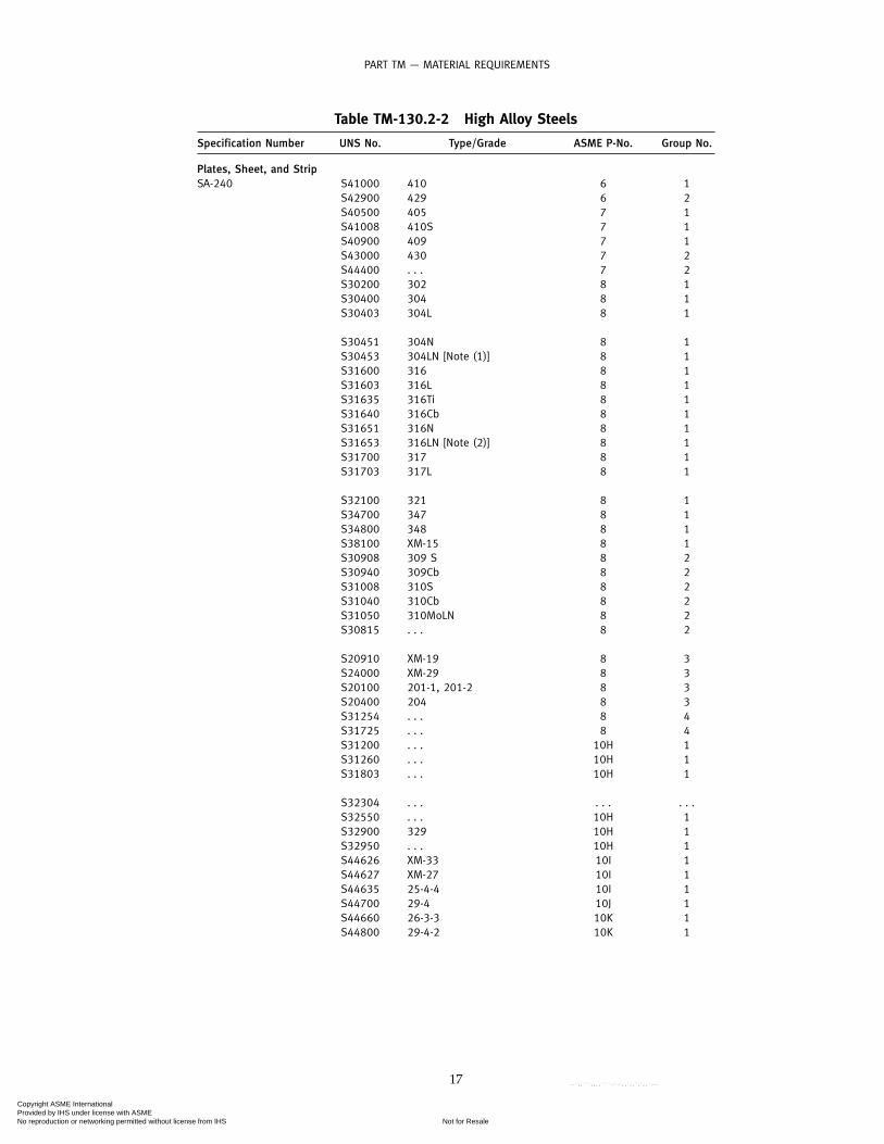
TM-220.1 Minimum Energy Requirements for TableTM-130.2-1 Materials With SpecifiedMinimum Tensile Strength Less Than 655MPa (95 ksi)
The applicable minimum energy requirement for allspecimen sizes shall be that shown in Fig. TM-220.1multiplied by the ratio of the actual specimen widthalong the notch to the width of a full-size specimen,except as otherwise provided in TM-210.2(b). The mini-mum impact test energy for one specimen shall not beless than two-thirds of the minimum average energyrequired for three specimens.
TM-220.2 Lateral Expansion Requirements for AllOther Steels
(a) Except for materials produced and impact-testedin accordance with the specifications listed in General
36
Note (c) of Fig. TM-220.1, the applicable minimum lat-eral expansion opposite the notch for all specimen sizesfor Table TM-130.2-1 materials having a specified mini-mum tensile strength of 655 MPa (95 ksi) or greater andfor Table TM-130.2-6 materials shall be not less than therequirements shown in Table TM-220.2. The minimumvalues for intermediate thicknesses may be obtained bystraight line interpolation.
(b) For Table TM-130.2-2 materials, the minimum lat-eral expansion opposite the notch shall be 0.38 mm (0.015in.) for minimum design metal temperatures (MDMTs)of −196°C (−320°F) and warmer. For MDMTs colder than−196°C (−320°F), the testing temperature shall be −196°C(−320°F) and the lateral expansion opposite the notchshall be not less than 0.53 mm (0.021 in.). (See also Fig.TM-220.2.)
TM-220.3 Impact Test Temperature Criteria
For all Charpy impact tests, the following test temper-ature criteria shall be observed:
(a) For Materials of Thickness Equal to or Greater Than10 mm (0.394 in.). Where the largest obtainable CharpyV-notch specimen has a width along the notch of at least8 mm (0.315 in.) (see Fig. TM-210.2), the Charpy test ofsuch a specimen shall be conducted at a temperature notwarmer than the minimum design metal temperature.Where the largest possible test specimen has a widthalong the notch less than 8 mm (0.315 in.), the test shallbe conducted at a temperature colder than the minimumdesign metal temperature by the amount shown in TableTM-220.3 for the specimen width. [This requirementdoes not apply when the option of TM-210.2(b) is used.]
(b) For Materials With Thickness Less Than 10 mm (0.394in.). Where the largest obtainable Charpy V-notch speci-men has a width along the notch of at least 80% of thematerial thickness, the Charpy test of such a specimenshall be conducted at a temperature not warmer thanthe minimum design metal temperature.1
Where the largest possible test specimen has a widthalong the notch of less than 80% of the material thick-ness, the test for Table TM-130.2-1 materials having aspecified minimum tensile strength of less than 655 MPa(95 ksi), shall be conducted at a temperature colder thanthe minimum design metal temperature by an amountequal to the difference (referring to Table TM-220.3)between the temperature reduction corresponding to theactual material thickness and the temperature reductioncorresponding to the Charpy specimen width actuallytested. [This requirement does not apply when theoption of TM-210.2(b) is used.] For Table TM-130.2-1materials having a specified minimum tensile strengthgreater than or equal to 655 MPa (95 ksi), and for TablesTM-130.2-2 and TM-130.2-6 materials, the test shall be
1 Where applicable for materials listed in Table TM-130.2-1, theimpact test temperature may be adjusted in accordance with TableTM-210.1.
Copyright ASME International Provided by IHS under license with ASME
Not for ResaleNo reproduction or networking permitted without license from IHS
--`,,```,,,,````-`-`,,`,,`,`,,`---
PART TM — MATERIAL REQUIREMENTS
Maximum Nominal Thickness of Materials or Weld, mm (in.)
CV, J
(ft
-lb
) (a
vera
ge
of
thre
e sp
ecim
ens)
25 (1.0) 50 (2.0) ≥75 (3.0)0
14 (10)
20 (15)
27 (20)
41 (30)
54 (40)
68 (50)
10 mm (0.394 in.)
≤262 MPa (38 ksi)
310 MPa (45 ksi)
344 MPa (50 ksi)
379 MPa (55 ksi)
≥448 MPa (65 ksi)
Minimum specifiedyield strength
GENERAL NOTES:(a) Interpolation between yield strengths is permitted.(b) The minimum impact energy value for one specimen shall not be less than two-thirds of the average energy required
for three specimens.(c) Material produced and impact tested in accordance with SA-320, SA-333, SA-334, SA-350, SA-352, SA-420, SA-437, SA-
540 (except for materials produced under Table 2, Note 4 in SA-540), and SA-765 do not have to satisfy these energyvalues. They are acceptable for use at minimum design metal temperature not colder than the test temperature whenthe energy values required by the applicable specification are satisfied.
(d) For materials having a specified minimum tensile strength of 655 MPa (95 ksi) or more, see TM-220.2.
Fig. TM-220.1 Charpy V-Notch Impact Test Requirements for Full-Size Specimens for Carbon and LowAlloy Steels, Having Specified Minimum Tensile Strength Less Than 95 ksi, Listed in Table TM-130.2-1
37
Copyright ASME International Provided by IHS under license with ASME
Not for ResaleNo reproduction or networking permitted without license from IHS
--`,,```,,,,````-`-`,,`,,`,`,,`---

TM-220.3 TM-220.42004 SECTION XII
Table TM-220.2 Minimum LateralExpansion Requirements
Minimum Charpy V-NotchMaximum Nominal Thickness, Lateral Expansion, mm (mils)
mm (in.) [Note (1)]
≤ 32 (11⁄4) 0.38 (15)54 (21⁄8) 0.51 (20)75 (3) 0.64 (25)
NOTE:(1) Straight line interpolation for intermediate values is permitted.
10 mm(0.394 in.)
Width along notch
Charpy V-Notch Specimen
Broken Specimen
a
A−A
Impact
b
B−B
A
A
B
B
2 mm(0.079 in.)
Fig. TM-220.2 Illustration of Lateral Expansion ina Broken Charpy V-Notch Specimen
conducted at a temperature not warmer than the mini-mum design metal temperature.
TM-220.4 Retest
(a) For Absorbed Energy Criteria. If the absorbed energycriteria are not met, retesting in accordance with theapplicable procedures of SA-370 shall be permitted.
(b) For Lateral Expansion Criteria(1) Retesting is permitted only if the average value
for three specimens equals or exceeds the value required(a) for Table TM-130.2-1 materials having speci-
fied minimum tensile strengths of 655 MPa (95 ksi) orgreater and for Table TM-130.2-6 materials, if the mea-sured value of lateral expansion for one test specimenin a group of three is less than that required by TableTM-220.2
38
Table TM-220.3 Charpy Impact Test TemperatureReduction Below Minimum Design Metal
Temperature (MDMT)
Actual Material Thickness [See TM-220.3(b)] of Charpy ImpactSpecimen Width Along the Notch [Note (1)]
Thickness, Temperature Reduction,mm (in.) °C (°F)
10.01 (full-size standard bar) (0.394) 0 (0)8.99 (0.354) 0 (0)8.00 (0.315) 0 (0)7.49 (3⁄4 size bar) (0.295) 3 (5)7 (0.276) 4 (8)6.7 (2⁄3 size bar) (0.262) 6 (10)5.99 (0.236) 8 (15)5.00 (1⁄2 size bar) (0.197) 11 (20)4 (0.158) 17 (30)3.33 (1⁄3 size bar) (0.131) 19 (35)3.00 (0.118) 22 (40)2.51 (1⁄4 size bar) (0.099) 28 (50)
GENERAL NOTE: For Table TM-130.2-1 materials having a specifiedminimum tensile strength of less than 655 MPa (95 ksi), when thesubsize Charpy impact width is less than 80% of the materialthickness.
NOTE:(1) Straight line interpolation for intermediate values is permitted.
(b) for materials of Table TM-130.2-2 for MDMTsno colder than −196°C (−320°F), if the measured valueof lateral expansion for one test specimen in a group ofthree is less than 0.38 mm (0.015 in.), but not less than0.25 mm (0.010 in.)
(c) for materials of Table TM-130.2-2 for MDMTscolder than −196°C (−320°F), if the measured value oflateral expansion for one test specimen in a group ofthree is less than 0.53 mm (0.021 in.), but not less than0.38 mm (0.015 in.)
(d) for materials of Table TM-130.2-6, if the mea-sured value of lateral expansion for one specimen in agroup of three is less than that required in Table TM-220.2, but not less than two-thirds of the required value
(2) The retest shall consist of three additional speci-mens. For materials listed in Table TM-130.2-6 and forTable TM-130.2-1 materials having specified tensilestrengths of 655 MPa (95 ksi) or greater, the retest valuefor each specimen must equal or exceed the value listedin Table TM-220.2. For Table TM-130.2-2 materials, theretest value for each specimen must equal or exceed0.38 mm (0.015 in.) for MDMTs no colder than −196°C(−320°F).
(3) If the required values are not obtained in theretest, or if the values in the initial test are less thanminimum required for retest, the material may be reheat-treated. After reheat treatment, a set of three specimensshall be made; for acceptance, the lateral expansion ofeach of the specimens must equal or exceed the mini-mum required values in Table TM-220.2.
Copyright ASME International Provided by IHS under license with ASME
Not for ResaleNo reproduction or networking permitted without license from IHS
--`,,```,,,,````-`-`,,`,,`,`,,`---

TM-220.4 TM-230.4PART TM — MATERIAL REQUIREMENTS
(c) When an erratic result is caused by a defectivespecimen or there is uncertainty in the test procedure,a retest will be allowed. When the option of TM-220.2(b)is used for the initial test and the acceptance of 100 J(75 ft-lbf) minimum is not attained, retest using full-size (10 mm � 10 mm) specimens will be allowed.
TM-230 IMPACT TEST REQUIREMENTS FORWELDED JOINTS
TM-230.1 Impact Testing of Welds
(a) For steel vessels of welded construction, theimpact toughness of welds and heat-affected zones ofprocedure qualification plates and vessel impact testplates (production impact test plates) shall be deter-mined as herein required.
(b) All test plates shall be subjected to heat treatment,including cooling rates and aggregate time at tempera-ture or temperatures as established by the Manufacturerfor use in actual manufacture. Heat treatment require-ments of TM-140.1, TF-310.2, TF-610.3, and TF-610.4 shallapply to the test plates, except that the provisions ofTF-310.2(f) are not applicable to plates joining P-Nos. 1and 2 materials.
TM-230.2 Location, Orientation, Temperature, andValues of Weld Impact Tests
All welded joint impact tests shall comply with thefollowing:
(a) Each set of weld metal impact specimens shall betaken across the weld with the notch in the weld metal.Each specimen shall be oriented so that the notch isnormal to the surface of the material and one face ofthe specimen shall be within 1.6 mm (1⁄16 in.) of thesurface of the material.
(b) Each set of heat-affected zone impact test speci-mens shall be taken across the weld and of sufficientlength to locate, after etching, the notch in the heat-affected zone. The notch shall be cut approximately nor-mal to the material surface in such a manner as to includeas much of the heat-affected zone material as possiblein the resulting fracture.
(c) For welds made of solid-state welding process,such as for electric resistance welded pipe, the weldimpact tests shall consist only of one set of three speci-mens taken across the weld with the notch at the weldcenterline. Each specimen shall be oriented such thatthe notch is normal to the surface of the material andone face of the specimen shall be within 1.6 mm (1⁄16 in.)of the surface of the material. The weld impact tests arenot required if the weld and the base metal have beenannealed, normalized, or quenched and tempered.
(d) The test temperature for welds and heat affectedzones shall not be higher than required for the basemetal.
39
(e) Impact test values shall be at least as high as thoserequired for the base metal.
TM-230.3 Impact Tests of Welding ProcedureQualifications
(a) General. For steel vessels of welded construction,the impact toughness of the welds and heat-affectedzones of the procedure qualification test plates shallbe determined in accordance with TM-230.2 and therequirements specified in TM-230.3(a) through (d).
(b) When Required. Welding procedure impact testsshall be made when required by TM-240.2, TM-250, orTM-260.3. For vessels constructed of carbon and lowalloy steels in Table TM-130.2-1, the test plate materialshall satisfy the following requirements relative to thematerial to be used in production:
(1) be of the same P-Number and Group Numberfor ferrous materials and the same P-Number and UNSNumber for nonferrous materials
(2) meet the minimum notch toughness require-ments of TM-220.1 for the thickest material of the rangeof base material qualified by the procedure (see Fig. TM-220.1).
If impact tests are required for the weld metal, butthe base metal is exempted from impact tests (as in TM-250), welding procedure test plates shall be made. Thetest plate material shall be material of the same P-Num-ber and Group Number used in the vessel. One set ofimpact test specimens shall be taken with the notchapproximately centered in the weld metal and perpen-dicular to the surface; the heat-affected zone need notbe impact-tested.
When the welding procedure employed for produc-tion welding is used for fillet welds only, it shall bequalified by a groove weld qualification test. The qualifi-cation test plate or pipe material shall meet the require-ments of TM-210 when impact testing is a requirement.
(c) Material Over 38 mm (11⁄2 in.) Thick. When proce-dure tests are made on material over 38 mm (11⁄2 in.) inthickness, three sets of impact test specimens arerequired. One set of heat-affected zone specimens shallbe taken as described in TM-230.2(b). Two sets of impacttest specimens shall be taken from the weld with oneset located near [within 1.6 mm (1⁄16 in.)] the surface ofone side of the material and one set taken as near aspractical midway between the surface and the center ofthickness of the opposite side as described in TM-230.2.
(d) Supplementary Essential Variables. The additionalsupplementary essential variables described in SectionIX, QW-250, for impact testing are required.
TM-230.4 Vessel (Production) Impact Test Plates
(a) General. In addition to the requirements of TM-230.3, impact tests of welds and heat-affected zones shallbe made in accordance with TM-230.2 for each qualified
Copyright ASME International Provided by IHS under license with ASME
Not for ResaleNo reproduction or networking permitted without license from IHS
--`,,```,,,,````-`-`,,`,,`,`,,`---

TM-230.4 TM-240.12004 SECTION XII
welding procedure used on each vessel or group of ves-sels as defined in TM-230.4(c). The vessel impact testplate shall be one of the heats of steel used for the vesselor group of vessels. For Category A joints, the test plateshall, where practicable, be welded as an extension tothe end of a production joint so that the test plate weld-ment will represent as nearly as practicable the qualityand type of welding in the vessel joint. For Category Bjoints that are welded using a different welding proce-dure than used on Category A joints, a test plate shallbe welded under the production welding conditionsused for the vessel, using the same type of equipmentand at the same location and using the same proceduresas used for the joint, and it shall be welded concurrentlywith the production welds or as close to the start ofproduction welding as practicable.
(b) When Required. Vessel (production) impact testplates shall be made for all joints for which impact testsare required for the welding procedure by TM-240.2,TM-250, and TM-260.3 (except where production testplates are specifically exempt by these paragraphs). Testsshall be made of the weld metal and/or heat-affectedzone to the extent required by the procedure test (seeTM-240.2, TM-250, and TM-260.3).
(c) Number of Impact Test Plates Required(1) For each vessel, one test plate shall be made for
each welding procedure used for joints of Categories Aand B, unless the vessel is one of several as defined inTM-230.4(c)(2). In addition, for Categories A and B jointsthe following shall apply:
(a) If automatic or semiautomatic welding is per-formed, a test plate shall be made in each positionemployed in the vessel welding.
(b) If manual welding is also employed, a testplate shall be made in the flat position only; except ifwelding is to be performed in other positions, a testplate need be made in the vertical position only (wherethe major portions of the layers of welds are depositedin the vertical upward direction). Qualifications in thevertical position shall qualify that manual process in allpositions.
(2) For several vessels or parts of vessels, weldedwithin any 3-month period at one location, the platethickness of which does not vary by more than 6 mm(1⁄4 in.), or 25%, whichever is greater, and of the samespecification and grade of material, a test plate shall bemade for each 120 m (400 ft) of joints welded by thesame procedure.
TM-230.5 Rejection
If the vessel test plate fails to meet the impact testrequirements, the weld(s) represented by the plate shallbe unacceptable. Reheat treatment and retesting, orretesting only, are permitted.
40
TM-240 IMPACT TEST REQUIREMENTS FORCARBON AND LOW ALLOY STEELS
TM-240.1 For Carbon and Low Alloy Steels,Dependent on Design Temperature
Figure TM-240.1-1 shall be used to establish impacttesting exemptions for steels listed in Table TM-130.2-1. Unless otherwise exempted by the rules of Section XII,impact testing is required for a combination of minimumdesign metal temperature [see TD-140(b)] and thickness(as defined below), which is below the curve assignedto the subject material. If a minimum design metal tem-perature and thickness combination is on or above thecurve, impact testing is not required by the rules ofSection XII, except as required by TM-240.2 for weldmetal and heat-affected zones. See also Table TM-240.1.
Components such as shells, heads, nozzles, manways,reinforcing pads, stiffening rings, flanges, flat coverplates, backing strips, and attachments that are essentialto the structural integrity of the vessel when welded topressure-retaining components shall be treated as sepa-rate components. Each component shall be evaluatedfor impact test requirements based on its individualmaterial classification, thickness as defined in TM-240.1(a), (b), or (c), and the minimum design metal tem-perature. The following thickness limitations applywhen using Fig. TM-240.1-1.
(a) Excluding castings, the governing thickness tg ofa welded part is as follows:
(1) for butt joints, except those in flat heads, thenominal thickness of the thickest welded joint [see Fig.TM-240.1-2, sketch (a)]
(2) for corner, fillet, or lap-welded joints, includingattachments as defined above, the thinner of the twoparts joined
(3) for flat heads, the larger of TM-240.1(a)(2) orthe flat component thickness divided by 4
(4) for welded assemblies comprised of more thantwo components (e.g., nozzle-to-shell joint with reinforc-ing pad), the governing thickness and permissible mini-mum design metal temperatures of each of theindividual welded joints of the assembly shall be deter-mined, and the warmest of the minimum design metaltemperatures shall be used as the permissible minimumdesign metal temperature (MDMT) of the welded assem-bly [see Fig. TM-240.1-2, sketch (b)]
(b) The governing thickness of a casting shall be itslargest nominal thickness.
(c) The governing thickness of flat nonwelded parts,such as bolted flanges and flat heads, is the flat compo-nent thickness divided by 4.
(d) The governing thickness of a nonwelded dishedhead is the greater of the flat flange thickness dividedby 4 or the minimum thickness of the dished portion.
Examples of the governing thickness for some typicalvessel details are shown in Fig. TM-240.1-2.
Copyright ASME International Provided by IHS under license with ASME
Not for ResaleNo reproduction or networking permitted without license from IHS
--`,,```,,,,````-`-`,,`,,`,`,,`---

PART TM — MATERIAL REQUIREMENTS
Min
imu
m D
esig
n M
etal
Tem
per
atu
re, º
C (
ºF)
-62 (-80)
Nominal Thickness, mm (in.)
Impact testing required
A
C
B
D
-50 (-60)
-40 (-40)
-48 (-55)
-29 (-20)
-18 (0)
-7 (20)
4 (40)
16 (60)
27 (80)
38 (100)
49 (120)
60 (140)
10 (0.394) 25 (1) 50 (2) 75 (3)
Fig. TM-240.1-1 Impact Test Exemption Curves[See Notes (1) and (2)]
41
Copyright ASME International Provided by IHS under license with ASME
Not for ResaleNo reproduction or networking permitted without license from IHS
--`,,```,,,,````-`-`,,`,,`,`,,`---

2004 SECTION XII
GENERAL NOTES ON ASSIGNMENT OF MATERIALS TO CURVES:(a) Curve A applies to
(1) all carbon and all low alloy steel plates, structural shapes, and bars not listed in Curves B, C, and D below(2) SA-216 Grades WCB and WCC if normalized and tempered or water-quenched and tempered; SA-217 Grade WC6 if
normalized and tempered or water-quenched and tempered(b) Curve B applies to
(1) SA-216 Grade WCA if normalized and tempered or water-quenched and temperedSA-216 Grades WCB and WCC for thicknesses not exceeding 50 mm (2 in.), if produced to fine grain practice and
water-quenched and temperedSA-285 Grades A and BSA-414 Grade ASA-515 Grade 60SA-516 Grades 65 and 70 if not normalizedSA-612 if not normalizedSA-662 Grade B if not normalizedSA/EN 10028-2 P295GH as-rolled;
(2) except for cast steels, all materials of Curve A if produced to fine grain practice and normalized which are not listedin Curves C and D below;
(3) all pipe, fittings, forgings and tubing not listed for Curves C and D below;(4) parts permitted under TM-110.10 shall be included in Curve B even when fabricated from plate that otherwise
would be assigned to a different curve.(c) Curve C
(1) SA-302 Grades C and DSA-516 Grades 55 and 60 if not normalizedSA-662 Grade A
(2) all material of Curve B if produced to fine grain practice and normalized and not listed for Curve D below.(d) Curve D
SA-203SA-508 Grade 1SA-516 if normalizedSA-524 Classes 1 and 2SA-537 Classes 1, 2, and 3SA-612 if normalizedSA-662 if normalizedSA-738 Grade ASA-738 Grade A with Cb and V deliberately added in accordance with the provisions of the material specification, not
colder than −29°C (−20°F)SA-738 Grade B not colder than −29°C (−20°F)SA/EN 10028-2 P295GH if normalized [see Note (g)(3)]SA/EN 10028-3 P275NH
General Notes and Notes continue on next page
Fig. TM-240.1-1 Impact Test Exemption Curves (Cont’d)
42
Copyright ASME International Provided by IHS under license with ASME
Not for ResaleNo reproduction or networking permitted without license from IHS
--`,,```,,,,````-`-`,,`,,`,`,,`---

PART TM — MATERIAL REQUIREMENTS
GENERAL NOTES ON ASSIGNMENT OF MATERIALS TO CURVES (CONT’D):(e) For bolting and nuts, the following impact test exemption temperature shall apply:
Bolting
Impact Test ExemptionSpec. No. Grade Diameter, mm (in.) Temperature, °C (°F)
SA-193 B5 Up to 100 (4), incl. −29 (−20)B7 Up to 65 (21⁄2), incl. −48 (−55)
Over 65 (21⁄2) to 180 (7) −40 (−40)B7M Up to 65 (21⁄2), incl. −48 (−55)B16 Up to 180 (7), incl. −29 (−20)
SA-307 B All −29 (−20)SA-320 L7, L7A, Up to 65 (21⁄2), incl. See General Note (c) of Fig. TM-220.1
L7M, Up to 65 (21⁄2), incl. See General Note (c) of Fig. TM-220.1L43 Up to 25 (1), incl. See General Note (c) of Fig. TM-220.1
SA-325 1 13 to (1⁄2) to 38 (11⁄2) −29 (−20)SA-354 BC Up to 100 (4), incl. −18 (0)SA-354 BD Up to 100 (4), incl. −7 (20)SA-437 B4B, B4C All diameters See General Note (c) of Fig. TM-220.1SA-449 . . . Up to 75 (3), incl. −29 (−20)SA-540 B21 Cl. All All Impact test required
B22 Cl. 3 Up to 100 (4), incl. Impact test requiredB23 Cl. 1, 2 All Impact test requiredB23 Cl. 3, 4 Up to 150 (6), incl. See General Note (c) of Fig. TM-220.1B23 Cl. 3, 4 Over 150 (6) to 240 (91⁄2), incl. Impact test requiredB23 Cl. 5 Up to 200 (8), incl. See General Note (c) of Fig. TM-220.1B24 Cl. 5 Over 200 (8) to 240 (91⁄2), incl. Impact test requiredB24 Cl. 1 Up to 150 (6), incl. See General Note (c) of Fig. TM-220.1B24 Cl. 1 Over 150 (6) to 200 (8), incl. Impact test requiredB24 Cl. 2 Up to 180 (7), incl. See General Note (c) of Fig. TM-220.1B24 Cl. 2 Over 180 (7) to 240 (91⁄2), incl. Impact test requiredB24 Cl. 3, 4 Up to 200 (8), incl. See General Note (c) of Fig. TM-220.1B24 Cl. 3, 4 Over 200 (8) to 240 (91⁄2), incl. Impact test requiredB24 Cl. 5 Up to 240 (91⁄2), incl. See General Note (c) of Fig. TM-220.1B24V Cl. 3 All See General Note (c) of Fig. TM-220.1
Nuts
Spec. Impact Test ExemptionNo. Grade Temperature, °C (°F)
SA-194 2, 2H, 2HM, 3, 4, 7, 7M, and 16 −55 (−48)SA-540 B21/B22/B23/B24/B24V −55 (−48)
(f) When no class or grade is shown, all classes or grades are included.(g) The following shall apply to all material assignment notes.
(1) Cooling rates faster than those obtained by cooling in air, followed by tempering, as permitted by the material spec-ification, are considered to be equivalent to normalizing or normalizing and tempering heat treatments.
(2) Fine grain practice is defined as the procedure necessary to obtain a fine austenitic grain size as described inSA-20.
(3) Normalized rolling condition is not considered as being equivalent to normalizing.
NOTES:(1) Tabular values for this Figure are provided in Table TM-240.1.(2) Castings not listed in General Notes (a) and (b) above shall be impact tested.
Fig. TM-240.1-1 Impact Test Exemption Curves (Cont’d)
43
Copyright ASME International Provided by IHS under license with ASME
Not for ResaleNo reproduction or networking permitted without license from IHS
--`,,```,,,,````-`-`,,`,,`,`,,`---

TM-240.1 TM-240.22004 SECTION XII
Table TM-240.1 Tabular Values forFig. TM-240.1-1
Thickness, Curve A, Curve B, Curve C, Curve D,in. °F °F °F °F
0.25 18 −20 −55 −550.3125 18 −20 −55 −550.375 18 −20 −55 −550.4375 25 −13 −40 −550.5 32 −7 −32 −55
0.5625 37 −1 −26 −510.625 43 5 −22 −480.6875 48 10 −18 −450.75 53 15 −15 −420.8125 57 19 −12 −380.875 61 23 −9 −360.9375 65 27 −6 −331 68 31 −3 −30
1.0625 72 34 −1 −281.125 75 37 2 −261.1875 77 40 4 −231.25 80 43 6 −211.3125 82 45 8 −191.375 84 47 10 −181.4375 86 49 12 −161.5 88 51 14 −14
1.5625 90 53 16 −131.625 92 55 17 −111.6875 93 57 19 −101.75 94 58 20 −81.8125 96 59 22 −71.875 97 61 23 −61.9375 98 62 24 −52 99 63 26 −4
2.0625 100 64 27 −32.125 101 65 28 −22.1875 102 66 29 −12.25 102 67 30 02.3125 103 68 31 12.375 104 69 32 22.4375 105 70 33 32.5 105 71 34 4
2.5625 106 71 35 52.625 107 73 36 62.6875 107 73 37 72.75 108 74 38 82.8125 108 75 39 82.875 109 76 40 92.9375 109 77 40 103 110 77 41 11
GENERAL NOTE: See Fig. TM-240.1-1 for SI values.
44
TM-240.2 Impact Tests of Welding Procedures
Except as exempted by TM-240.4(a), the Welding Pro-cedure Qualification for welded construction shallinclude impact tests of welds and heat-affected zonesmade in accordance with TM-230 when required by thefollowing provisions. The MDMT used below shall bethe MDMT stamped on the nameplate, or the exemptiontemperature of the welded component before applyingthe temperature reduction permitted by TM-240.3(a) orTM-240.4(g):
(a) Welds made with filler metal shall be impact-tested in accordance with TM-210 and TM-230 whenany of the following apply:
(1) when either base metal is required to be impact-tested by the rules of this Section, or
(2) when joining base metals from Fig. TM-240.1-1 Curves C or D, or metals exempted from impact testingby TM-240.4(f), and the minimum design metal temper-ature is colder than −29°C (−20°F) but not colder than−48°C (−55°F), unless welding consumables that havebeen classified by impact tests at a temperature notwarmer than the MDMT by the applicable SFA specifica-tion are used
(3) when joining base metals exempt from impacttesting by TM-240.4(f) when the design metal tempera-ture is colder than −48°C (−55°F).
(b) Welds in materials listed in Table TM-130.2-1 madewithout the use of filler metal shall be impact-testedwhen the thickness of the weld exceeds 13 mm (1⁄2 in.)for all minimum design metal temperatures or whenthe thickness at the weld exceeds 8 mm (5⁄16 in.) and theminimum design metal temperature is colder than 10°C(50°F).
(c) Weld heat-affected zones produced with or with-out the addition of filler metal shall be impact-testedwhenever any of the following apply:
(1) when the base metal is required to be impact-tested by the rules of this Section
(2) when the welds have any individual weld passexceeding 13 mm (1⁄2 in.) in thickness, and the minimumdesign metal temperature is colder than 21°C (70°F)
(3) when joining base metals exempt from testingby TM-240.4(f) when the minimum design metal tem-perature is colder than −48°C (−55°F)
(d) Vessel (production) impact tests in accordancewith TM-230.4 may be waived for any of the following:
(1) weld metals joining steels exempted fromimpact testing by TM-240.1 or TM-240.4 for minimumdesign metal temperatures of −29°C (−20°F) or warmer
(2) weld metals defined in TM-240.2(a)(2) and (a)(3)(3) heat-affected zones in steels exempted from
impact testing by TM-240.1 or TM-240.4, except whenTM-240.2(c)(3) applies
Copyright ASME International Provided by IHS under license with ASME
Not for ResaleNo reproduction or networking permitted without license from IHS
--`,,```,,,,````-`-`,,`,,`,`,,`---

TM-240.3 TM-240.3PART TM — MATERIAL REQUIREMENTS
Fig. TM-240.1-2 Some Typical Tank Details Showing the Governing Thicknesses as Defined in TM-240.1
TM-240.3 For Carbon and Low Alloy Steels,Dependent on Design Stress Values
(a) When the coincident ratio defined in Fig. TM-240.3-1 is less than one, Fig. TM-240.3-1 provides a basisfor the use of components made of Table TM-130.2-1materials without impact testing at MDMT colder thanthat derived from TM-240.1.
(1) For such components, and for MDMT of −48°C(−55°F) and warmer, the MDMT without impact testingas determined in TM-240.1 for the given material andthickness may be reduced as determined from Fig. TM-240.3-1. If the resulting temperature is colder than therequired MDMT, impact testing of the material is notrequired.
(2) Figure TM-240.3-1 may also be used for compo-nents not stressed in general primary membrane tensilestress, such as flat heads, covers, and flanges (including
45
bolts and nuts). The MDMT of these components with-out impact testing as determined in TM-240.1 or TM-240.4(b) may be reduced as determined from Fig. TM-240.3-2. The ratio used in Step 3 of Fig. TM-240.3-2 shallbe the ratio of maximum design pressure at the MDMTto the maximum allowable pressure (MAP) of the com-ponent at the MDMT. If the resulting temperature iscolder than the required MDMT, impact testing of thematerial is not required, provided the MDMT is notcolder than −48°C (−55°F).
(3) In lieu of using TM-240.3(a)(2), the MDMTdetermined in TM-240.1 or TM-240.4(b) may be reducedfor a flange attached by welding, by the same reductionas determined in TM-240.3(a)(2) for the neck or shell towhich the flange is attached. The bolt-up condition neednot be considered when determining the temperaturereduction for flanges.
Copyright ASME International Provided by IHS under license with ASME
Not for ResaleNo reproduction or networking permitted without license from IHS
--`,,```,,,,````-`-`,,`,,`,`,,`---

2004 SECTION XII
Fig. TM-240.1-2 Some Typical Tank Details Showing the Governing Thicknesses as Defined in TM-240.1(Cont’d)
46
Copyright ASME International Provided by IHS under license with ASME
Not for ResaleNo reproduction or networking permitted without license from IHS
--`,,```,,,,````-`-`,,`,,`,`,,`---

TM-240.3 TM-240.4PART TM — MATERIAL REQUIREMENTS
tA
tB
tA
tB
Pressure partPressure part
1
A
B
1 1
A
B
tg1 � thinner if tA or tB
(f) Welded Attachments as Defined in TM-240.1
GENERAL NOTE: tg p governing thickness of the welded joint as defined in TM-240.1.
Fig. TM-240.1-2 Some Typical Tank Details Showing the Governing Thicknesses as Defined in TM-240.1(Cont’d)
(4) When the minimum design metal temperatureis colder than −48°C (−55°F), impact testing is requiredfor all materials, except as allowed in TM-240.3(a)(5)and TM-240.4(g).
(5) When the minimum design metal temperatureis colder than −48°C (−55°F) and not colder than −104°C(−155°F), and the coincident ratio defined in Fig. TM-240.3-1 is less than or equal to 0.35, impact testing isnot required.
(b) The exemptions in TM-240.3(a) apply to those ves-sels in which the pressure is dependent on the vaporpressure of the contents (e.g., vessels subject to low sea-sonal atmospheric temperatures). For such services, theprimary thickness calculations normally will be madefor the maximum design pressure coincident with themaximum temperature expected on or above the line inFig. TM-240.1-1 for the applicable group of materials,using the appropriate design stress values in Section II,Part D. Thickness calculations then will be made for themaximum coincident pressure expected below the linein Fig. TM-240.1-1 for the applicable group of materialsusing the reduced design stress value(s). The greater ofthe thickness so calculated shall be used. Comparison ofpressure ratios or stress ratios may suffice when loadingsnot caused by pressure are insignificant.
TM-240.4 Other Requirements and Exemptions forCarbon and Low Alloy Steels
(a) Impact testing in accordance with Article TM-2 isnot mandatory for tank materials, which satisfy all ofthe following:
(1) The material shall be limited to P-No. 1, Gr. No.1 or 2, and the thickness as defined in TM-240.1 shallnot exceed that given in TM-240.4(a)(1)(a) and (a)(1)(b):
(a) 6 mm (1⁄4 in.) for materials listed in Curve Aof Fig. TM-240.1-1
47
(b) 13 mm (1⁄2 in.) for materials listed in CurveB, C, or D of Fig. TM-240.1-1
(2) The completed vessel shall be hydrostaticallytested in accordance with Article TT-2 of Section XII.
(3) The design temperature is neither warmer than343°C (650°F) nor colder than −29°C (−20°F).
(4) Thermal or mechanical shock loadings are nota controlling design requirement (see TD-200).
(5) Cyclic loading is not a controlling designrequirement (see TD-200).
(b) No impact testing is required for ASME B16.5 andASME B16.47 ferritic steel flanges used at design metaltemperatures not colder than −29°C (−20°F).
(c) No impact testing is required for Table TM-130.2-1 materials with a thickness of 2.5 mm (0.10 in.) andthinner, but such exempted Table TM-130.2-1 materialsshall not be used at design metal temperatures colderthan −48°C (−55°F). For vessels or components madefrom DN 100 (NPS 4) or smaller tubes or pipe of P-No. 1 materials, the following exemptions from impacttesting are also permitted as a function of the material’sspecified minimum yield strength (SMYS) for metal tem-peratures of −104°C (−155°F) and warmer:
SMYS, MPa (ksi) Thickness, mm (in.)
140 to 240 (20 to 35) 6.0 (0.237)250 to 310 (36 to 45) 3.2 (0.125)315 (46) and higher 2.5 (0.10)
(d) The material Manufacturer’s identification mark-ing die required by the material specification shall notbe stamped on plate material less than 6 mm (1⁄4 in.) inthickness unless the following requirements are met:
(1) The materials shall be limited to P-No. 1 GroupNos. 1 and 2.
Copyright ASME International Provided by IHS under license with ASME
Not for ResaleNo reproduction or networking permitted without license from IHS
--`,,```,,,,````-`-`,,`,,`,`,,`---

2004 SECTION XII
Rat
io: t
rE*/
(tn
- c)
; See
No
men
clat
ure
fo
r A
lter
nat
ive
Rat
io
0.00
0.10
0.20
0.40
0.60
0.80
1.00
0 11 (20) 22 (40) 33 (60) 45 (80)
ºC (ºF) [See TM-240.4(h)]
0.35
See TM-240.3(a)(4) when ratios are 0.35 and smaller
56 (100) 67 (120) 78 (140)
Nomenclature (Note reference to General Notes of Fig. TM-240.3-2)tr p required thickness of the component under consideration in the corroded condition for all applicable
loadings [General Note (b)], based on the applicable joint efficiency E [General Note (c)], mm (in.)tn p nominal thickness of the component under consideration before corrosion allowance is deducted,
mm (in.)c p corrosion allowance, mm (in.)
Alternative Ratio p S*E* divided by the product of the maximum allowable stress value for materials Table TM-130.2-1times E, where S* is the applied general primary tensile stress and E and E* are as defined in Gen-eral Note (c)
Fig. TM-240.3-1 Reduction in Minimum Design Metal Temperature Without Impact Testing
48
Copyright ASME International Provided by IHS under license with ASME
Not for ResaleNo reproduction or networking permitted without license from IHS
--`,,```,,,,````-`-`,,`,,`,`,,`---

PART TM — MATERIAL REQUIREMENTS
Repeat for all governing thickness [General Note (e)] and take warmest value as the lowest allowable MDMT to be marked on nameplate for the zone under consideration [General Note (j)]. See TS-100.See TT-220 for coldest recommended metal temperature during hydrostatic test [General Note (f)].See TT-210(b) for coldest metal temperature permitted during pneumatic test [General Note (f)].
Determine adjusted MDMT for governing thickness under consideration.
Requirement
Legend
Optional General Notes follow on next page
Using Ratio from Step 3 to enter ordinate of Fig. TM-240.3-1, determine reduction in Step 2 MDMT [General Note (i)].
Select MDMT from Fig. TM-240.1-1 [General Note (d)] for each nominal noncorroded governing thickness [General Note (e)].
Step 1
Step 2
Step 3
Step 4
Step 5
Step 6
Establish nominal thickness [General Note (a)] of welded parts, nonwelded parts, and attachments under consideration both before and after corrosion allowance is deducted (tn and tn – c, respectively), and other pertinent data applicable to the nominal thickness such as:
All applicable loadings [General Note (b)] and coincident minimum design metal temperature (MDMT)Materials of constructionEtntr
c
===
=
joint efficiency [General Note (c)]nominal noncorroded thickness [General Note (a)], mm (in.)required thickness in corroded condition for all applicable loadings [General Note (b)],based on the applicable joint efficiency [General Note (c)], mm (in.)
corrosion allowance, mm (in.)Applicable curve(s) of Fig. TM-240.1-1
Determine Ratio:
[General Notes (c), (f), (g), and (h)]
tr Etn – c
Fig. TM-240.3-2 Diagram of TM-240.1 Rules for Determining Lowest Minimum Design MetalTemperature (MDMT) Without Impact Testing
49
Copyright ASME International Provided by IHS under license with ASME
Not for ResaleNo reproduction or networking permitted without license from IHS
--`,,```,,,,````-`-`,,`,,`,`,,`---

TM-240.4 TM-240.42004 SECTION XII
GENERAL NOTES to FIG. TM-240.3-2:(a) For pipe where a mill undertolerance is allowed by the material specification, the thickness after the mill
undertolerance has been deducted shall be taken as the noncorroded nominal thickness, tn, for determination of theMDMT to be stamped on the nameplate. Likewise, for formed heads, the minimum specified thickness after formingshall be used as tn.
(b) Loadings, including those listed in TD-200, which result in general primary membrane tensile stress at the coincidentMDMT.
(c) E is the joint efficiency (Table TW-130.4) used in the calculation of tr; E* has a value equal to E, except that E* shallnot be less than 0.80. For castings, use quality factor or joint efficiency E, whichever governs design.
(d) The construction of Fig. TM-240.1-1 is such that the MDMT so selected is considered to occur coincidentally with theapplied general primary membrane tensile stress at the maximum allowable stress value in tension from Section II PartD. Tabular values for Fig. TM-240.1-1 are shown in Table TM-240.1.
(e) See TM-240.1(a), (b), and (c) for definitions of governing thickness.(f) If the basis for calculated test pressure is greater than the design pressure, a Ratio based on the tr determined from
the basis for calculated test pressure and associated appropriate value of tn − c shall be used to determine therecommended coldest metal temperature permitted during the pneumatic test. See TT-210(a)(3) and TT-210(b)(5).
(g) Alternatively, a Ratio of S*E* divided by the product of the maximum allowable stress value in tension fromSection II,Part D, times E may be used, where S* is the applied general membrane tensile stress and E and E* are as defined inGeneral Note (c).
(h) For TM-240.3(b) and TM-240.4(h), a ratio of the maximum design pressure at the MDMT to the maximum allowablepressure (MAP) at the MDMT shall be used. The maximum MAP is defined as the highest permissible pressure asdetermined by the design formulas for the component using the nominal thickness less corrosion allowance and themaximum allowable stress value from Section II, Part D at the MDMT. For ferritic steel flanges defined in TM-220.4(b),the flange rating at the warmer of the MDMT or 38°C (100°F) may be used as the MAP.
(i) For reduction in MDMT up to and including 4°C (40°F), the reduction can be determined by: reduction in MDMT p(1 − Ratio) 38°C [MDMT p (1 − Ratio) 100°F].
(j) A colder MDMT may be obtained by selective use of impact-tested materials as appropriate to the need (see TM-210).See also TM-240.4(g).
Fig. TM-240.3-2 Diagram of TM-240.1 Rules for Determining Lowest Minimum Design MetalTemperature (MDMT) Without Impact Testing (Cont’d)
(2) The minimum nominal plate thickness shall be5 mm (0.1875 in.) or the minimum nominal pipe wallthickness shall be 4 mm (0.154 in.).
(3) Minimum design metal temperature shall benot colder than −29°C (−20°F).
(e) Unless specifically exempted in Fig. TM-240.1-1,materials having a SMYS greater than 450 MPa (65 ksi)must be impact-tested.
(f) Materials produced and impact-tested in accor-dance with specifications listed in Fig. TM-220.1, Gen-eral Note (c), are exempt from impact testing by therules of this Section at minimum design metal tempera-tures not more than 3°C (5°F) colder than the test temper-ature required by the specification.
(g) If postweld heat treating is performed when it isnot otherwise a requirement of Section XII, a 17°C (30°F)reduction in the temperature at which impact testing isrequired by Fig. TM-240.1-1 is permitted for P-No. 1materials (see TF-320.1).
(h) For components made of Table TM-130.2-1 materi-als that are impact-tested, Fig. TM-240.3-1 provides abasis for the use of these components at a MDMT colderthan the impact test temperature, provided the coinci-dent ratio defined in Fig. TM-240.3-1 is less than oneand the MDMT is not colder than −104°C (−155°F).
50
(1) For such components, the MDMT shall be notcolder than the impact test temperature less the allow-able temperature reduction as determined from Fig. TM-240.3-2.
(2) Figure TM-240.3-1 may also be used for compo-nents not stressed in primary membrane tensile stress,such as flat heads, covers, tubesheets, and flanges(including bolts and nuts). The MDMT shall be notcolder than the impact test temperature less the allow-able temperature reduction as determined from Fig. TM-240.3-2. The ratio used in Step 3 of Fig. TM-240.3-2 shallbe the ratio of maximum design pressure at the MDMTto the maximum allowable pressure (MAP) of the com-ponent at the MDMT.
(3) In lieu of using TM-240.4(h)(2), the MDMT fora flange attached by welding shall be not colder than theimpact test temperature less the allowable temperaturereduction as determined in TM-240.4(h)(1) for the neckor shell to which the flange is attached.
NOTE: The bolt-up condition need not be considered whendetermining the temperature reduction for flanges.
(i) No impact testing is required for metal backingstrips, which remain in place, made of materialsassigned to Curve A of Fig. TM-240.1-1 in thicknesses
Copyright ASME International Provided by IHS under license with ASME
Not for ResaleNo reproduction or networking permitted without license from IHS
--`,,```,,,,````-`-`,,`,,`,`,,`---

TM-240.4 TM-250.4PART TM — MATERIAL REQUIREMENTS
not exceeding 6 mm (1⁄4 in.) when the minimum designtemperature is −29°C (−20°F) or warmer.
TM-250 IMPACT TEST REQUIREMENTS FOR HIGHALLOY STEELS
Impact tests employing the lateral expansion criterionof TM-220.2 shall be performed on materials listed inTable TM-130.2-2 for all combinations of materials andminimum design metal temperatures, except asexempted by TM-250.1, TM-250.2, TM-250.3, or TM-250.4.
TM-250.1 Required Impact Testing of Base Metal,Heat-Affected Zones, and Weld Metal
(a) Impact tests shall be made from sets of three testspecimens: base metal, heat-affected zone, and weldmetal. The specimens shall be subjected to the sameheat treatments2 as the part or vessel that the specimensrepresent. Test procedures, size, location, and orientationof the specimen shall be the same as required in TM-220 and TM-230.
(b) Each of the three specimens tested in each set shallhave a lateral expansion opposite the notch not less than0.38 mm (0.015 in.) for MDMTs of −196°C (−320°F) andwarmer.
(c) When MDMT is −196°C (−320°F) and warmer, andthe average value of lateral expansion of the three speci-mens in a set equals or exceeds 0.38 mm (0.015 in.), butthe value of lateral expansion for one specimen of thatset is less than 0.38 mm (0.015 in.), but not less than 0.25mm (0.010 in.), a retest of three additional specimensmay be made in accordance with TM-220.4(b).
(d) When MDMT is colder than −196°C (−320°F), pro-duction welding processes shall be limited to shieldedmetal arc welding (SMAW), gas metal arc welding(GMAW), and gas tungsten arc welding (GTAW). Notchtoughness testing shall be performed as specified in TM-250.1(d)(1) and TM-250.1(d)(2), as appropriate.
(1) If using Type 316L weld filler metal(a) each heat of filler metal used in production
shall have a Ferrite Number (FN) not greater than 5, asdetermined by applying the chemical composition fromthe test weld to Fig. TM-250.1
(b) notch toughness testing of base metal, weldmetal, and heat-affected zone (HAZ) shall be conductedusing a test temperature of −196°C (−320°F)
(c) each of the three test specimens from eachtest set shall have a lateral expansion opposite the notchnot less than 0.53 mm (0.021 in.)
(2) If using filler metals other than Type 316L, orwhen the base metal, weld metal, or filler metal areunable to meet the requirements of TM-250.1(d)(1)
2 Thermal treatments of materials are not intended to includewarming to temperatures not exceeding 316°C (600°F), thermalcutting, or welding.
51
(a) notch toughness testing shall be conducted ata test temperature not warmer than MDMT, using theASTM E 1820 JIC method
(b) a set of two specimens shall be tested in theT-L orientation3 with the resulting KIC (J) of not less than132 Mpa�m (120 ksi�in.)
(c) each heat or lot of filler metal used in produc-tion shall have a ferrite number (FN) not greater thanthe FN determined for the test weld.
TM-250.2 Required Impact Testing for WeldingProcedure Qualifications
For welded construction, the Welding ProcedureQualification shall include impact tests of welds andheat-affected zones (HAZs) made in accordance withTM-230.3 and with the requirements of TM-250.1, whenany of the components4 of the welded joint are requiredto be impact-tested by the rules of Section XII.
TM-250.3 Required Impact Tests When ThermalTreatments are Performed
Impact tests are required at the colder of 21°C (70°F)or the minimum design metal temperature, wheneverthermal treatments within the temperature ranges listedfor the following materials are applied:
(a) austenitic stainless steels thermally treatedbetween 482°C and 900°C (900°F and 1,650°F), exceptTypes 304, 304L, 316, and 316L, which are thermallytreated at temperatures between 482°C and 704°C (900°Fand 1,300°F), are exempt from impact testing, providedthe MDMT is −29°C (−20°F) and warmer and vessel(production) impact tests of the thermally treated weldmetal are performed for Categories A and B joints
(b) austenitic-ferritic duplex stainless steels thermallytreated at temperatures between 316°C and 954°C (600°Fand 1,750°F)
(c) ferritic chromium stainless steels and martensiticchromium stainless steels thermally treated at tempera-tures between 427°C and 732°C (800°F and 1,350°F).
TM-250.4 Exemptions From Impact Testing for BaseMetals and Heat-Affected Zones
Impact testing is not required for Table TM-130.2-2base metals when the nominal thickness is less than 2.5mm (0.099 in.).
Impact testing is not required for the following combi-nations of base metals and heat-affected zones (ifwelded) and minimum design metal temperatures(MDMTs), except as modified in TM-250.3.
(a) For austenitic chromium-nickel stainless steels asfollows:
(1) Types 304, 304L, 316, 316L, 321, and 347 atMDMTs of −196°C (−320°F) and warmer
3 See ASTM E 399, Fig. 1, for test specimen and crack planeorientation in rectangular sections (e.g., plate).
4 Either base metal or weld metal.
Copyright ASME International Provided by IHS under license with ASME
Not for ResaleNo reproduction or networking permitted without license from IHS
--`,,```,,,,````-`-`,,`,,`,`,,`---

2004 SECTION XII
Fig.
TM-2
50.1
Wel
dM
etal
Del
taFe
rrit
eCo
nten
t
52
Copyright ASME International Provided by IHS under license with ASME
Not for ResaleNo reproduction or networking permitted without license from IHS
--`,,```,,,,````-`-`,,`,,`,`,,`---

TM-250.4 TM-250.6PART TM — MATERIAL REQUIREMENTS
(2) those not listed in TM-250.4(a)(1) and having acarbon content not exceeding 0.10% at MDMTs of−196°C (−320°F) and warmer
(3) having a carbon content exceeding 0.10% atMDMTs of −48°C (−55°F) and warmer
(4) for castings at MDMTs of −29°C (−20°F) andwarmer
(b) For austenitic chromium-manganese-nickel stain-less steels (200 series) as follows:
(1) having a carbon content not exceeding 0.10% atMDMTs of −196°C (−320°F) and warmer
(2) having a carbon content exceeding 0.10% atMDMTs of −48°C (−55°F) and warmer
(3) for castings at MDMTs of −29°C (−20°F) andwarmer
(c) For the following cast and wrought steels atMDMTs of −29°C (−20°F) and warmer:
(1) austenitic-ferritic duplex steels with a nominalthickness of 10 mm (3⁄8 in.) and thinner
(2) ferritic chromium stainless steels with a nomi-nal thickness of 3.2 mm (1⁄8 in.) and thinner
(3) martensitic chromium stainless steels with anominal thickness of 6 mm (1⁄4 in.) and thinner
Carbon content as used in TM-250.4(a) and (b) is asspecified by the purchaser and must be within the limitsof the material specification.
TM-250.5 Exemptions From Impact Testing forWelding Procedure Qualifications
For welding procedure qualifications, impact testingis not required for the following combinations of weldmetals and MDMTs, except as modified in TM-250.3:
(a) for austenitic chromium-nickel stainless steel basematerials having a carbon content not exceeding 0.10%,welded without the addition of filler metal, at MDMTsof −104°C (−155°F) and warmer
(b) for austenitic weld metal(1) having a carbon content not exceeding 0.10%
and produced with filler metals conforming to SFA-5.4,SFA-5.9, SFA-5.11, SFA-5.14, and SFA-5.22 at MDMTs of−104°C (−155°F) and warmer
(2) having a carbon content exceeding 0.10% andproduced with filler metals conforming to SFA-5.4, SFA-5.9, SFA-5.11, SFA-5.14, and SFA-5.22 at MDMTs of−48°C (−55°F) and warmer
(c) for the following weld metal, when the base metalof similar chemistry is exempt as stated in TM-250.4(c),then the weld metal shall also be exempt at MDMTs of−29°C (−20°F) and warmer:
(1) austenitic-ferritic duplex steels(2) ferritic chromium stainless steels(3) martensitic chromium stainless steels
TM-250.6 Required Impact Testing for Vessel(Production) Plates
For welded construction, vessel (production) impacttests in accordance with TM-230.4 are required if the
53
Welding Procedure Qualification requires impact testingunless otherwise exempted by the rules of this Section.
Vessel (production) impact tests are not required forwelds joining austenitic chromium-nickel or austeniticchromium-manganese-nickel stainless steels at MDMTsnot colder than −196°C (−320°F) where all of the follow-ing conditions are satisfied:
(a) The welding processes are limited to shieldedmetal arc, submerged arc, gas metal arc (GMAW andFCAW), gas tungsten arc, and plasma arc.
(b) The applicable Welding Procedure Specifications(WPSs) are supported by Procedure Qualification Rec-ords (PQRs) with impact testing in accordance with therequirements of TM-210 (using the acceptance criteriaof TM-250.1) at the minimum design metal temperatureor colder, or when the applicable PQR is exempted fromimpact testing by other provisions of Section XII.
(c) The weld metal (produced with or without theaddition of filler metal) has a carbon content notexceeding 0.10%.
(d) The weld metal is produced by filler metal con-forming to SFA-5.4, SFA-5.9, SFA-5.11, SFA-5.14, andSFA-5.22 as modified below.
(1) Each heat and/or lot of welding consumablesto be used in production welding with the shieldedmetal arc (SMAW) and gas metal arc (GMAW) processesshall be qualified by conducting impact tests at or belowthe MDMT, except as exempted by TM-250.5(b) in accor-dance with Section II, Part C, SFA-5.4, A9.12. Acceptancecriteria shall conform with TM-250.1.
(2) Each heat of welding consumables to be usedin production welding with the submerged arc (SAW)process shall be qualified by conducting impact testswith each lot and/or batch of flux at or below the MDMT,except as exempted by TM-250.5(b) in accordance withSection II, Part C, SFA-5.4, A9.12. Acceptance criteriashall conform with TM-250.1.
(3) Combining more than one welding process ormore than one heat, lot, and/or batch of welding mate-rial into a single test coupon is unacceptable. Testing ator below the MDMT, except as exempted by TM-250.5(b)may be conducted by the welding consumable manufac-turer, provided certified mill test reports are furnishedwith the consumables.
(4) The following filler metals may be used withoutimpact testing of each heat and/or lot, provided thatprocedure qualification impact testing in accordancewith TM-230.3 at the minimum design metal tempera-ture or colder is performed using the same manufacturerbrand and type filler metal: ENiCrFe-2; ENiCrFe-3;ENiCrMo-3; ENiCrMo-4; ENiCrMo-6; ERNiCr-3;ERNiCrMo-3; ERNiCrMo-4; SFA-5.4, E310-15 or 16.
(5) The following filler metals may be used withoutimpact testing of each heat and/or lot, provided thatprocedure qualification impact testing in accordance
Copyright ASME International Provided by IHS under license with ASME
Not for ResaleNo reproduction or networking permitted without license from IHS
--`,,```,,,,````-`-`,,`,,`,`,,`---

TM-250.6 TM-260.32004 SECTION XII
with TM-230.3 at the minimum design metal tempera-ture or colder is performed: ER308L, ER316L, and ER310used with GMAW, GTAW, or PAW processes.
TM-250.7 Exemption From Impact Testing Because ofLow Stress
Impact testing of materials listed in Table TM-130.2-2 is not required, except as modified by TM-250, whenthe coincident ratio of design stress5 in tension to allow-able tensile stress is less than 0.35.
TM-260 IMPACT TEST REQUIREMENTS FORFERRITIC STEELS WITH TENSILEPROPERTIES ENHANCED BY HEATTREATMENT
TM-260.1 General
(a) All steels listed in Table TM-130.2-6 shall be testedfor notch ductility, as required by TM-260.2. These testsshall be conducted at a temperature not warmer thanthe minimum design metal temperature [see TD-140(b)],but not warmer than 0°C (32°F). Materials may be usedat temperatures colder than the minimum design metaltemperature as limited in TM-260.1(a)(1) and (2).
(1) When the coincident ratio defined in Fig. TM-240.3-1 is 0.35 or less, the corresponding minimumdesign metal temperature shall be not colder than−104°C (−155°F).
(2) When the coincident ratio defined in Fig. TM-240.3-1 is greater than 0.35, the corresponding minimumdesign metal temperature shall not be colder than theimpact test temperature less the allowable temperaturereduction permitted in Fig. TM-240.3-1 and shall in nocase be colder than −104°C (−155°F).
(b) All test specimens shall be prepared from thematerial in its final heat-treated condition or from full-thickness samples of the same heat similarly and simul-taneously treated. Test samples shall be of such size thatthe prepared test specimens are free from any changein properties due to edge effects.
(c) Where the vessel or vessel parts are to be hot-formed or postweld heat-treated (stress-relieved), thisidentical heat treatment shall be applied to the test speci-mens required by the material specifications includingthe cooling rate specified by the fabricator, which shallin no case be slower than that specified in the applicablematerial specifications.
TM-260.2 Impact Test Requirements
(a) Test Specimen and Test Procedures(1) One Charpy V-notch test (three specimens) shall
be made from each plate as heat treated, and from eachheat of bars, pipe, tube, rolled sections, forged parts, or
5 Applied stress from pressure and nonpressure loadings (seeTD-200).
54
castings included in any one heat treatment lot.(2) The test procedures, and size, location, and ori-
entation of the specimens shall be the same as requiredby TM-210.1, except that for plates, the specimens shallbe oriented transverse to the final direction of rollingand for circular forgings, the specimens shall be orientedtangential to the circumference.
(3) Each of the three specimens tested shall have alateral expansion opposite the notch not less than therequirements in Table TM-220.2.
(4) If the value of lateral expansion for one speci-men is less than that required in Table TM-220.2 but notless than two-thirds of the required value, a retest ofthree additional specimens may be made, each of whichmust be equal to or greater than the required value inTable TM-220.2. Such a retest shall be permitted onlywhen the average value of the three specimens is equalto or greater than the required value in Table TM-220.2.If the values required are not obtained in the retest orif the values in the initial test are less than the valuesrequired for retest, the material may be reheat-treated.After reheat treatment, a set of three specimens shall bemade, each of which must be equal to or greater thanthe required value in Table TM-220.2.
(b) Materials conforming to SA-353 and SA-553 foruse at minimum design metal temperatures colder than−196°C (−320°F), materials conforming to SA-517, SA-543, and SA-592 for use at minimum design metal tem-peratures colder than −29°C (−20°F), and materials con-forming to SA-645 for use at minimum design metaltemperatures colder than −171°C (−275°F) shall have, inaddition to the Charpy tests required under TM-260.2(a),drop-weight tests as defined by ASTM E 208, Conduct-ing Drop-Weight Tests to Determine Nil Ductility Transi-tion Temperatures of Ferritic Steels, made as follows:
(1) For plates 16 mm (5⁄8 in.) thick and over, onedrop-weight test (two specimens) shall be made for eachplate as heat-treated.
(2) For forgings and castings of all thicknesses, onedrop-weight test (two specimens) shall be made for eachheat in any one heat treatment lot using the procedurein SA-350 for forgings and in SA-352 for castings.
(3) Each of the two test specimens shall meet the“no-break” criterion, as defined by ASTM E 208, at thetest temperature.
TM-260.3 Welded Joints
(a) For welded vessels, the deposited weld metal andthe heat-affected zone shall meet the impact test require-ments of TM-210.1 and TM-230, except that the CharpyV-notch tests and requirements of TM-260.2(a) shallapply.
Copyright ASME International Provided by IHS under license with ASME
Not for ResaleNo reproduction or networking permitted without license from IHS
--`,,```,,,,````-`-`,,`,,`,`,,`---
TM-260.3 TM-270PART TM — MATERIAL REQUIREMENTS
(b) The following materials are exempt from produc-tion impact tests of the weld metal in accordance withTM-210.1 and TM-230 under the conditions given inTM-260.3(b)(1) through (5):
P-No./Specification No. UNS No. Group No.
SA-353 K81340 11A/1SA-522 Type I K81340 11A/1SA-553 Type I K81340 11A/1SA-553 Type II K41583 11A/1SA-645 K41583 11A/1
(1) One of the following high nickel alloy filler met-als is used:
Specification No. Classification F-No.
SFA-5.11 ENiCrMo-3 43SFA-5.11 ENiCrMo-6 43SFA-5.11 ENiCrFe-2 43SFA-5.11 ENiCrFe-3 43SFA-5.14 ERNiCr-3 43SFA-5.14 ERNiCrFe-6 43SFA-5.14 ERNiCrMo-3 43SFA-5.14 ERNiCrMo-4 44
(2) All required impact tests shall be performed aspart of the procedure qualification tests as specified inTM-230.
(3) Production impact tests of the heat-affectedzone are performed in accordance with TM-230.4.
55
(4) The welding processes are limited to gas metalarc, shielded metal arc, and gas tungsten arc.
(5) The minimum allowable temperature of thetank shall be not less than −196°C (−320°F).
TM-270 USE OF NONFERROUS MATERIALS ATLOW TEMPERATURES
The materials in Tables TM-130.2-3, TM-130.2-4, TM-130.2-5, and TM-130.2-7, together with deposited weldmetal within the range of composition for materials inthose tables, do not undergo a marked drop in impactresistance at subzero temperatures. Therefore, no addi-tional requirements are specified for wrought aluminumalloys when they are used at temperatures down to−269°C (−452°F); for copper and copper alloys, nickeland nickel alloys, and cast aluminum alloys when theyare used at temperatures down to −196°C (−320°F); andfor titanium and titanium alloys used at temperaturesdown to −59°C (−75°F). The materials listed in TablesTM-130.2-3, TM-130.2-4, TM-130.2-5, and TM-130.2-7may be used at lower temperatures than those specifiedherein and for other weld metal compositions, providedthe User satisfies himself by suitable test results, suchas determinations of tensile elongation and sharp notchtensile strength (compared to unnotched tensilestrength), that the material has suitable ductility at thedesign temperature.
Copyright ASME International Provided by IHS under license with ASME
Not for ResaleNo reproduction or networking permitted without license from IHS
--`,,```,,,,````-`-`,,`,,`,`,,`---