Embed Size (px)
Citation preview

1. Introduction
The image iconoscope is a television pick-up tube of the high-velocitytype. A description of this tube has recently heen given in Philips tech-nical Review 1).
R 173
*) At present with Kon. Ned. Meteor. Inst., De Bilt, Netherlands.
Philips Res. Rep. 6, 323-346, 1951
PARAXIAL IMAGE FORMATIONIN THE "MAGNETIC" IMAGE ICONOSCOPE
by J. C. FRANCKEN and R. DORRESTEIN *) .
537.533.3: 621.385.832 :621.397.611Summary
In this paper a method is described for computing paraxial raysin a cathode lens placed in a magnetic field. In order to judge theapproximations made, the well-known derivation of the ray equationis given. The solutions of this equation are discussed and a physicalinterpretation is given. A special case, approximating the electron-optical system in the image iconoscopc, is computed numerically.The electron trajectories thus found lead to a discussionof the imagingmechanism in these electron-optical systems. In some respects themechanism appears to differ considerably from that in ordinarymagnetic lenses.
Résumé
Dans eet article on dëcrit une méthode pour Ie calcul des rayonsparaxiaux dans une lentille cathodique, placëe dans un champ mag-nëtique, Afin de juger des approximations faites, l'équation des rayonsest dérivée de la façon classique. On .discute les solutions de cetteéquation et on en doune une interprétation physique. Dans un casparticulier, voisin du système d'optique électronique de l'image-iconoscope, on a fait un calcul numërique. Les trajectoires ëlectro-niques ainsi trouvées condnisent à discuter Ie mécanisme de laformation d'image dans de tels systèmes d'optique électronique.A certains égards le mëcanisme apparnît diffërer considérablementde celui d'une lentille magnëtique ordinaire.
Zusammenfassung
Es wird eine Methode zur Berechnung von aehscnnahen Elektro-nenbahnen in einer komhiniert elektrisch-magnetisehen Immersions-linse besehrieben. Um die gemachten Vernaehlässigungen beurteilenzu können, wird dieBahngleichung in bekannter Weise abgeleitet. IhreLösungen werden diskutiert und physikalisch interpretiert. EinspezielIer Fall, welcher der Situation im Bildikonoskop schr ähnlichist, ist numerisch durchgerechnet worden. Die so gefundenen Elek-tronenbahnen führen zu einer Diskussion über den Abbildungs-mechanismus in solehen elektronenoptisehen Systemen. In mancherHinsicht weicht dieser Mechanismus von dem in normalen magne-tischen Linsen ab.

324 J. C. FRANCKEN and R. DORRESTEIN
The electron-optical system has been sketched in fig. 1. Opposite aflat, transparent photo-cathode is an anode cylinder. The potential differ-ence between these electrodes is usually about 1000 volts. Both cathodeand anode are placed in the field of a rather long coil in such a way thatthe magnetic induction B has its maximum value in the vicinity of thecathode.
'ï \f--I-t
c . ~.-.-._._._-_.-.-._._._.1-.1-.
67(119
Fig. 1. Sketch of the electron-optical system. The anode cylinder has a potentialof about .1000 volts with respect to the (transparent) photo-cathode. Thc latter is well-immersedin the magnetic field of a rather long colloThe image is projected onto the photo-cathodeby means of a suitable optical systcm; a = anode cylinder (glass cylinder with innermetallic coating); c = cathode; m = ir~m-clad coil; t = target.
This type of electron-optical system has been used in several types ofimage iconoscope 2). As yet, however, not very much has been publishedabout the mechanism of the image formation *). The purpose of this paperis to contrihute towards a clearer understanding of this image formation.Since integration of the ray equation in the vicinity of the cathode cannotbe carried out with the help of the well-known step-by-step methods, aseries approximation was applied. This method is very appropriate formaking numerical computations, and it is easier to apply than earliermethods 3). To judge the approximations made, the derivation of the rayequation is given.
NotationsRationalized m.k.s. units (Giorgi-system) are used throughout.
x, y, z - cartesian, orthogonal coordinates (right-handed system,cf. fig. 2); z = 0 is cathode plane.
T, e, z _ cylindrical coordinates (right-handed system, cf. fig. 2).T _ (X2+y2)'/., tan e =y]«,
*) In Heimann's "Entwicklungsgang der elektronischen Blldzerlegerröhren", Mitt,Forsch. Anst. D. Reichspost 5, 131-163, 1940, reference was made to work done byH. J.Wolff on this subject (Dipl. Arbeit T. H. Darmstadt, 1939). All efforts by theauthors to get a copy of this work have been in vain.

PARAXIAL ThL~GE FORMATION IN THE "IIIAGNETIC" IMAGE ICONOSCOPE 325
General-ray equations
The equations of motion for electrons in combined eleotrostatic andmagnetic fields with rotational symmetry about the same axis are 4), 6)
cp (r, z)
çp (z)
accent (')dot (")
index (0)B; (r, z)
B:; (r, z)B (0, z).
,eInCF, b, ah, kP'(z)
index pX (z)
u (z)w (z)Re
- potential in a system with axial symmetry about thez-axis at a point with coordinates r, z;potential along the axis of the above system, zero atthe cathode.
- differentiation with. respect to z.- differentiation with respect to t (time), when moving
with an electron.indication of the value of a function at the cathode.radial component of the magnetic-induction vectorB (r, z) at the point with coordinates r, z ill a systemwith axial symmetry ahout the z-axis.
- axial component of the above vector.- value of the magnetic induction at a point z of the axis,- charge of an electron (positive number).
mass of an electron (non-relativistic velocities).constant in, the ray equation.constants of the electrostatic field near the cathode.
- constants of the magnetic field near the cathode.angle of rotation of a "reference meridional plane"at a distance z from the cathode. '
- indicates a quantity of the principal ray.- angle between the meridional plane of an arbitrary
ray and the corresponding reference meridional plane,at a distance z from the cathode.
- complex quantity, defined by r(z)ix(.>.ray vector, defined by r(z)eie(z>."reduced" radial distance.
- initial kinetic energy of electrons emitted by the cathode.energies corresponding to initial velocities in radial,tangential and axial directions.
. e (öCP .)r - r€P = - - - rfJB:; ,m ör (1)
d e- (r2é) = - T(rB:; - zBr),dt m..
(2)
e (öCP .)z =- - + TfJBr •m öz
(3)

326 J. C. FRANCKEN nnd R. DORRESTEIN
An integral of motion can be obtained from eq. (2) alone. Introducingthe vector potential A, defined by
curIA=B, (4)
we have in the case of rotational symmetry, where all differential quotientswith respect to g must vanish,
1 o(rA)Bz = ---,
T or (4a)
oABr=--,oz
(4b)
where A stands for AC'), the tangential (and only) component of A. Suhsti-tution of these equations in (2) results in
d . e d- (r2g) = -- (rA).dt m dt
(2a)
This equation can be integrated immediately:
. eC= r2g--rA.
m(5)
Owing to the symmetry of the magnetic field, the vectorpotential A ata distance r from the axis is related directly to the magnetic flux (M)through a disk of radius r, set normal to the axis.
Acèording to Stokes' theorem we have .
M = J B:dO"= J (curl A)z de = fAds,a a
. or, for the above-mentioned disk,r
M = 2n J Brrdr = f Adr= 2nrA.o
Thus we have MrA=-,
2n
and eq. (5) can consequently be written as
. eC = r2(:) ---M.
2nm(5a)
Integration of the general equations (1), (2) and" (3) JP.-u!'t,of course,yield an energy integral, viz.,
(6)

PARAXIAL IMAGE FORMATION IN THE "MAGNETIC" IMAGE ICONOSCOPE 32i
where e is a constant for each electron, representing its initial energyat the cathode (cp = 0).In the following the three parts of the kinetic energy of an electron
indicated at the left of eq. (6) will be simply indicated by the adjectivesradial, tangential and axial respectively.The magnetic forces being perpendicular to the velocity vector, they
cannot increase the energy. Since, furthermore, there is no tangential com-,ponent of B, the magnetic forces cannot 'transform radial energy directlyinto axial energy, nor vice versa.
Schematically the possibilities of energy being transformed from onedirection into the others can be summarized as follows:
tangential(tm r2 ËJ2)
fBzj \Br'radial __ ____,..axial(t m ;-2) J_B!_)_ (t m z2) .
Hence, any change in the axial velocity due to magnetic forces is onlypossible if the induction vector has a radial component B«.
Paraxial-ray equations
From eqs (1), (2) and· (3) we see that the axis itself, r = 0, representsa possible electron path, or ray. Paraxial rays are rays in the vicinity ofthe axis. In deriving the paraxial-ray equations we therefore supposer to be "small" and thus we, can make the following approximations:
ocp- R:j q>'(z),oz
B;; (r,z) R:j B (O,z) ,
ocp R:j _!_ ([>"(z)ör 2 '
(7b)
r ,B; (r,z) R:j - _ B (O,z).2 (7d)
Space charges are ignored in this paper. Therefore, the electrostatic fieldis taken as being divergence-free, as is, of course, the magnetic field.When the continuity condition is applied to a small cylinder about theaxis, we get ~eqüations (7c) and (7d). In addition "wesim~lify eq. (6) to
tm Z2 R:j è q>(z) + sz, (7e)
(7a)
(7c)

J. C. FRA:.\"CKEN and R. DORRESTEIN
where Sz is the axial part of the initial energy of the electron. The conditionsof validity for (7e) will be discussed later on.
Employing these approximations we can derive the paraxial-ray equa-tions 4), G). Substituting
M R:i :n; r2 B(O,z)in eq. (Sa) yields
. e Ce = -B(O,z) +-,2m r2
(8)
and by eliminating the time from this equation by means of (7e) wc get
de' V C_ . _ e B(O,z) + . m "2'dz 18m(e çp + sz) 2(e <P+ sz) r
(9)
Substituting (8) in (1), using (7b) and (7c), and eliminating the time tby means of (7e) we get
/---- d (/--~dr') ( e2 l mC2
1eÇp(z) + Sz dz l eÇp(z) + Sz dz =- ~te<P" (z) + 8m B2(0,Z) S r + 2r3 • (10)
Equations (9) and (10) represent the two differe~tial equations describ-ing the paraxial rays. The additional terms Sz have only significance in theimmediate neighbourhood of the cathode; farther on they can mostly beomitted. In the following the case will be considered where Sz = 0. Theeffect on the shape of the rays caused by the term Sz is called "chromatic"aberration. The constant C is a function of the initial conditions, given bysubstituting z = ° in eq. (8):
2 ~ • e ~C= ro eo- -B(O,O) .. 2m(ll)
We still have to discuss in more detail under what conditions the approxi-mations (7a) .,. (7e) can be expected to be valid in practice. Anyhowwecan use the paraxial equations, supposing that the error made is small;if desired, this error can he determined by more exact calculations, orotherwise by experiments. Obviously it is impossible to give quantitativeconditions which should assure the applicability of eqs (9) and (10) witha given maximum error in any case that might occur, but a few roughindications can be given.
In general it may he' said that the radial distance r must be small com-pared with the distance between the axis and the nearby electrodes, orpole pieces. Only in that case can the power series in r, by which the quan-tities ocp/oz, Bz, o'cp/or, B; can be represented as functions of r near theaxis, be expected to be fairly approximated by their respective first terms,

PARAXIAL mAGE FORMATION 1:-: THE "MAGNETIC" UIAGE ICONOSCOPE 329
given in (7a) ... (7d). In the case of a cathode or anode surface intersectingthe axis the same will hold provided its radius of curvature is much greaterthan r and does not vary much in a range much greater than r. Itwould heconceivable for such an electrode to consist of magnetic material withoutviolating (7b) and (7d) in a certain range of r. '
The approximation (7e) can be found from eq. (3). Multiplying bothmembers of this equation by mz we get an energy equation which can beintegrated, using (7a), if the 'term ezr€JBr is ignored. The result is then (7e).As the term ezrëBr gives the rate of transformation of tangential intoaxial energy, or vice versa, this means that (7e) is only valid if the gainin tangential energy of the eiectr'on is small' compared with the total gainin kinetic energy. Thus especially near the cathode, the condition for (7e) is
oqJ •- '2"- reBroz s-: ,
or in words: the electrostatic field strength at the cathode must he muchhigher than the product of the radial component ofthe magnetic-inductionvector and the tangential component of the velocity. Far from the cathode,the meaning of approximation (7e) is that the total kinetic energy of theelectron must he almost entirely axial energy, if the paraxial relations areto be valid.
The paraxial rays obeying eqs (9) and (10) can be divided into two classes:(1) those with C = 0, (2) those with C =1= o.Considering (10), it may already be conjectured that, with C =1= 0,
r never becomes zero, i.e., that rays with C =1= 0 can never interseet theaxis, whereas rays with C = 0 can. In fact, later on a proof will he given ofthis important law. '
Since r represents a radius in a cylindrical coordinate system, it oughtto he either positive or zero. However, in view of the possibility of inter-section of the axis by rays with C = 0, discontinuities in r'; r" and e forsuch rays will he avoided by allowing also for negative values for functionsr (z) obeying (10). Then, the cylindrical coordinates of any point in spacemay he defined either as r, e, z, or as r*, e*, z, where r* = -r and e* == e ± st; The two sets of coordinates are mathematically equivalent sincethey both correspond to one set of values x = r cos e = r* cos e* andy = r sin e = r* sin e»,
2. Solutions of the paraxial-ray equations
Approximatior_: of the electrostatic and magnetic fields near the cathode
, In any practical case, when the field functions q.i(z) and B(O,z) are sup-posed to he known, an approximate solution of eqs (9) and (10) can be
(12)

330 J. C. FRANCKEN and R. DORRESfEIN
obtained by some step-by-step method. The solution is especially easyif the length of an interval along the z-axis is chosen such that the relativevariation of the various quantities in the differential equations within oneinterval is so small that these quantities can there be assumed to be con-stant. Close to the cathode, however, with Sz == 0, this condition cannot besatisfied since at the cathode W(z) is zero. Therefore it is recommendableto give the solutions near the cathode in the form of power series in z.
For small values of z we can approximate 'W(z) by
W(z) = Fz (1+ bz + az2 + ...). (13)
From this we derive
W'(z) = F (1+ 2bz + 3az2 + ...),W"(z) =F (2b + 6az + ...).
(14)
(15)
For a curved cathode, the constant b is given by
(16)
where (! is the radius of curvature (negative for a concave cathode). Thiswill be clear from the following. The radius of curvature of equipotentialsat T = 0 is generally given by
-2W'(z)(! = W" (z) (17)
This can be derived from Laplace's equation 4), 6). The cathode being anequipotential, W'(z) and W"(z) can be computed from (14) and (15) forz = 0 and T = O.The result is (16). For a flat cathode we therefore have
b = O. (IS)
The values of a and F can be taken from field plots, Fbeing the field strengthat the cathode at T = O. The magnetic field near the cathode may beapproximated by
SmB2(0,z) = - F (h + fez+ ...).e .
(19)
The choice of the constant SmFle will be clear from the following (eqs(24) and (25».
Solutions of the ray equations. First case (C = 0)
At the end of section 1 it was already mentioned that the paraxial raysobeying eqs (9) and (10) can be divided into two classes, ,dependent onwhether the constant C in these equations is zero or not for those rays.From eq. (11) it is seen that C = 0 in the following cases:

PARAXIAL IMAGE FORMATION IN THE "MAGNETIC" IMAGE ICONOSCOPE 331-----
(b) TO èo= 0,
(a) TO = 0, If TO =l= 0,two cases
i.e. for all elec- 11===========::::;:::===========trons startingin the centreof the cathode II---------------------~------------------~--
No magnetic field in thecathode region(B(O,O) = 0):
Magnetic field in thecathode region(B (0,0) =l= 0):
e(c) Toèo = - B(O,O)TO' (20)
2mi.e. 'for electrons without an i.e. for electrons with ainitial tangential component prescribed value of the initial
tangential coinponent
In the case where Sz = 0, eq. (10) reduces to
<P(z)T" + t<P'(z) T' + P(z) T= 0,with
eP(z) = !(/j" (z) + -- B2 (O,z) .
8m(21a)
Equation (9) becomes (with Sz = 0)
dP 11 e- = -B(Oz)dz 8m@"
and eq. (8)• eP= -B (O,z).
2m(22a)
In eqs (22) and (22a) we have replaced e by P. If e generally representsthe angle of a rotating meridional plane containing any particular ray,P will represent the angle of such a plane for electrons for which C = O.
Near the cathode the expressions (13), (14) and (15) can be substitutedin (21) and (21a). The result is a second-order linear differential equationwith a regular point at z = O. The solutions are of the form
Computing the coefficients of (23) from the differential equation, wefind the following two basic solutions near z = 0:
T1(Z)= 1- z(b + 2h) + z2(tb2 - ia + ih2 + ihb - ik) + ..., (24)
T2(Z) = z'!'~l-z(tb+ih) ~ Z2 (H-b2-ia+fsh2+ 17r;hb-tkH + ....(25)These solutions describe two special electron paths in the cathode region.
(21)
(22)
(23)

332 J. C. FRANCKEN and R. DORRESTEIN
Outside this region, the functions Tl(Z) and T2(Z) can be defined as the ex-tended solutions of the second-order differentlal equation (21) given, nearZ = 0, by (24) and (25). They can be computed by any step-by-step method,beginning at such a distance Z from the cathode that the power series (24)and (25) can still be approximated by their first three terms and that the"paraxial" conditions of section 1 hold.If the initial meridional planes of the rays Tl(z) and T2(Z), given by Po,
happen to be the same, they continue to proceed in the same rotating meri-dional plane. This plari.e cuts the initial meridional plane at an angleP-Po, to be found by integrating (22):
/
- ze B(O.C)
P(z) - Po = 1 - r / . dC·8m Ö 1 <1>(C)
(26)
For any initial value Po we can obtain the shape of any ray for whichC = 0 by linear combination of Tl (z) and T2 (z), as follows from the linearityof the differentlal equation (21). As already pointed out at the end of section 1we have to allow the functions T(Z) to be positive, zero or negative.
Equation (26) shows that for any value of z all electrons with C = 0are characterized by the same function g(z) - go = P(z) - Po' In thefollowing the meridional plane through, and rotating with, all these electronsstarting with C = 0 and with some initial value go = Po will be calledthe "reference meridional plane" corresponding to this value of go = Po'
The initial conditions for electrons describing the special paths (24)and (25) can be found by differentiating these equations with respect tot and using for small z the relation
For z = 0 we thus find
T10 = 1,T20= 0,
rIO .0,
1'20 = lim _;._, dz = lieF._0 2z' dt V 2m
(27a)
(27b)
(28a)
(28b)
The initial tangential velocities are found by combining (27) with (22a):
. e V2ehFTlOglO = - B(O,O) = --,
2m m(29)

PARA.XIAL IMAGE FORMATION IN THE ..l\[AGNETIC" IMAGE ICONOCSOPE 333
From eqs (27), (28) and (29) we can interpret the solutions (24) and (25)as follows:(a) T1(Z) is the paraxial path in the cathode region described hy an electronemitted hy the cathode at unit distance from the axis, without axial orradial velocity components. Its initial tangential velo city is givenhyeq. (29).(h) ,T2(Z) is the paraxial path described hy an electron emitted from theaxis point of the cathode with a radial velocity given hy (28h). There isno axial velocity component, as was stipulated in section l.
These trajectories, as might he expected, are special. cases- of thosementioned under (c) and (a) in the beginning of this section,
Solutions of the ray equations. Second case (C =1= 0)
The constant C in eqs (9) and nO) differs from zero for electrons leavingthe cathode from off-axis points with tangential velocity componentsdiffering from the value given hy eq. (20).According to eq., (ll) the .value of C is given by
2 S . e 2C= TO? e,- 2m B(O,O)s· (ll) .
If C =1= 0 this means that we are considering rays proceeding outside a"reference meridional plane" (as defined before).
We now compare such a ray with the rays starting with C = 0 and withthe same initial angle Po = eo at the cathode, and put
e(z) = P(z) + x(z) = e,+ j 1/8m~(C) B (O,C)dC + X(z), (31), ' . 0
from eq. (26). Thus X(z) is the angle between the actual meridional planeof the ray and the corresponding reference meridional plane.
From eqs (9) and (31) it follows that
X(z) ~ V;: ci ,'Jld~(I;) (32)
Now, for rays with C =1= 0 we define a complex quantity u(z) ,hy
u(z) = T(Z) eix(=) • (33)
At the cathode, since Xo = 0, Uo is still real and equal to TO. Now, it turnsout that the two paraxial-ray equations (10) and (32) can he combinedinto one simple differentlal equation for the complex variahle ~(z), whichequation appears to he identical with (21):
cjj(z)u" + tcjj'(z)u' + P(z)u = 0, (34)

334 J. C. FRANCKEN eud R. DORRESTEIN
where P(z) is again given by (21a). The equivalence of (34) and (33)on the one hand, and (10) and (32) on the other, is most easily shown bysubstituting (33) in (34), omitting the always-present factor eix, and work-ing out the imaginary and real parts respectively.
Since eq. (34) is identical with (21), it has two real solutions Ul(z)and u2(z), which are identical with T1(Z) and T2(Z), given near Z = 0, by(24) and (25). The general solution of (34) can thus be written as
(35)
where a and b are complex constants.If C differs from zero X will vary with z, according to (32), and u(z)
will he complex with varying argument, according to (33). Then botha and b in (35) must differ from zero and they must have different arguments.Since Ul(z) and u2(z), forming a pair of independent solutions of eq. (34),can never be zero at the same time, u(z) and therefore r(z) can neverhe zero. Thus the theorem that only paraxial rays with C = 0 caninterseet the axis has been proved. Consequently if C,* 0, r(z) in (33)can safely be assumed to be always positive.
The values of the complex constants a and b can be calculated from theinitial quantities TO' To, eo, io at the cathode. We take eo = 0 for the sakeof simplicity. Computing the initial quantities from (33) and (35) and com-paring them with the expressions (27) and (28), we find
a=To, b ·1/2m(70+iToXo),V eFso that (35) becomes
u(z) = Torl(z) + V2m(To + iroXo) T2 (z) .
eF(35a)
(Note 'that rl(z) and r2(z) as given by (24) and (25) have not the dimensionof a length, whereas the quantity ro has.)
If, at a certain value. of z, z = Zi,
(36a)
then from eq. (35a) it is seen that all electrons' from a given point of thecathode, irrespective of their radial or tangential velocity, interseet againin one point: we have an image of the cathode. For this reason the rayr2(z) will be denoted as the "central imaging ray". Moreover, from (35a)we see that in the image plane U(Zi) is again real, so that
X(Zi) = 0 or X(Zi) = ± 1"&,
depending on the sign of r1(zi).
(36b)

PARAXIAL IMAGE FORMATION IN THE "MAGNETIC" IMAGE ICONOSCOPE 335
Equation (35a) can he written in a somewhat different form. From eq., .(31) it follows that ' '.
Xo = êo- Po· . .The value of Po is found from eq. (22a), so that
. eXo= 80- 2m B(O,O).
The velocities in the radial and tangential directions can he expressed inthe equivalent energies Sr and Se, which are related to ro and eo by
~ y2m . V-;; 1/2m. y' Se. -ro=2 -, /-ro(:}0=2 -.eF cF eF eF
Thus finally eg. (35a) takes the following form:
u(z) = rOr1(z)+ S-iroB(O,O) 1/ e + 2J/ Sr + 2i 1/ 8e l r2(z)'.( V 2mF cF eF~(35h)
Principal and imaging rays
From (36) individual rays can he derived by choosing the initial con-ditions, i.e. ro' eo, Sr and Se. We now select the following case:
ro=l, 80=0, SI'=O, 8e=0, (andsz=O). (37)
We are thus considering the path of an electron leaving the cathode atunit distance from the axis with zero velocity in all' directions. Thepath of such an electron is called a principal ray. It is given, from (35h)and (37), hy
. up(z) = r1(z) -iB(O,O) ~ r2(z)= rp(z) ixp(:). (38)
This principal ray proceeds in the principal meridional plane, cutting thereference meridional plane at an angle Xp, given hy (32), (11) and (37):
(39)
I
If there is a magnetic field at the cathode then the principal ray is a raywith C =1= 0, and therefore it never intersects the axis. The general solution(35h) can now he expressed as a linear combination of the principalray up(z) and the central imaging ray r2(z):
S1/-;; Vse lu(z) = TOUp(Z)+ 2 ( V eF + i sF~ r2(z).

w(z) =x(z) + iy(z) =r(z) eU,J(zl.
Then from (31) and (33):
(41)
336 J. c. FRANCKEN and R. DORRESTEIN
By introducing rp(z) and Xp(z) and the initial energy ·components in theinitial energy
er = e cos2a , . • 2ee = e sm f1.,
this equation may be written as
(40)
In this equation a is the angle between the initial velocity vector and theméridional plane of the object point.
Picture of the imaging mechanismTo get a good idea of the imaging mechanism we shall express eq. (40)
in a somewhat different form. In using the vector quantity u(z) we have-been referring an electron path to the rotating reference meridionalplane as defined before. W.e now take the initial meridional plane of theobject point as a reference plane and let this plane coincide with thex-z-plane of a rectangular coordinate system x, y, z, the z-coordinatebeing the axis of symmetry. Then at the cathode we have eo = Po = o.The location of an eieciron in this rectangular coordinate system can bedefined by a complex function 'W(z):
w(z) = u(z) ei'P(zl, (41a)
and the solutions rl(z) and r2(z), for Po = 0, correspond to
'W1(z) = rl(z) i'P(zl, ~.(42)
'W2(z) = r2(z) iP(:l.
x
t----------)'1
,,' -: I",/ / :
,,' . p. ,,'" I(':----- --- --- : il ',e I :: r' : II ", I :I1 I,'I I'I I 'I 1,//______________ .Jo
-z
67100
Fig. 2. Relation between cylindrical coordinates r, e, zand orthogonal coordinates x,y, s.

PARAXIAL IMAGE FORMATION IN THE "l\rAGNETIC" IMAGE ICONOSCOPE 337
The principal-ray vector is defined by
In this equation we have for ep(z) fro~ (31)
ep(z) = P(z) + Xp(z) •
According to (41a) we find the general vector w(z) from (40) by multi-plying both members by eitp(:) and using (44):
The arguments ofthe terms on the right are given by (26) and (39), takingaccount of ~44):
(.V e ~ B(O,O)lep(z) = Ö 8m rp (e) ?B(O~C) - Tim ~de;
~(z) = j V8m ~ (e) B(O,e) de.o
The modulus of the principal ray can be calculated from (38):
Tp(Z) = 1/ T~(Z) + _e_ ~B(0,oH2 T~(Z).V 2mF
From (45) we arrive at the followingpicture ofthe imagingmechanism.,The electron paths can he found by adding two rotating vectors. One is'proportional to the principal-ray vector and describes the path of an elec-tron emitted with zero velocity. The other rotating vector is proportionalto the central imaging-ray vector, and its modulus and argument dependon the initial energy 8 and the angle a of the initial velocity with respectto the meridional plane. Thus each object point emits electron pencilswhich are symmetrical around the first-mentioned path. All electronsstarting with an initial radial and/or tangential velocity rotate around thispath and interseet it in the image plane (T2(z) = 0). Since,with B(O,O) =1= 0,the principal rays do not interseet the axis, there is no concentration pointof all electron pencils on the axis, i.e. there is no "cross-over".
(43)
(44)
(45)
(46)
(47)
(48)

338 . J. C. FRAl.'!CKEN and R. DORRESTEIN
3. Electron paths in the "magnetic" image iconoscope
Numerical evaluation of the paths
As already stated in section 2, the special rays r1(z) and r2(z) can betraced further outside the cathode region by integrating eq. (21). Thiscan be done by any step-by-stép method 5). However, for this integrationW"(z) has to be known fairly accurately. Therefore we prefer to use theray equation in the form
d2R-+f(z)R=O,dz2
(49)
with
(50)
Equation (49) can he. deduced from (21) by substituting
r = R ~q>.(zH-'/ -. (51)
The special 'solutions of eq. (49) near the cathode can be expressed inseries which are equivalent to (24) and (25):
R1(z) = z'/. ~1-z(-ib + 2h) + z2(!¥b2-±a + -ih2+ -fi-hb-tk) + ",~, (52)
Rz(z) =z'I'~I~z(±b +th) 4 z2(Tl!ob2-"2'\a +-hhz + -fohb-!k) +...~.(53)The step-by-step integration of (49) is begun at such a value of z that thefirst three terms of the series (52) and (53), written out here, are still afair approximation. In this case some values of R can be computed inboth ways, so that the accuracy of the approximations made can be checked.
Computation of a special (idealized) case
In order to get an idea of the electron paths in the "magnetic" imageiconoscope it is not necessary to know very accurately the field along theaxis. We can consider some representative approximations. ,If the distance between the cathode and the anode cylinder is very
small compared with the inner diameter of the latter,' the potential distri-bution can be calculated mathematically. The solution has been presentedin numerical form, e.g., by Bertram 7). The potential W(z) along the axis,for an acceleration voltage of 1000 volts is plotted in fig. 3..The distribution of the magnetic induction along the axis may be
aPJ?roximated by.'
B(O,z) = s,e-pï. (54)

PARAXIAL IMAGE FORMATION IN THE "MAGNETIC" IJllAGE ICONOSCOPE 339
If an iron-clad coil is used, for which the distance between the polepieces d is approximately equal to the inner diameter D of the latter, thefield along the axis is given to a good approximation by (54). The value ofplD as a function of dID has been measured by Van Ments and Le Poole 8).
(V)
1~OOx
12M 1MIV: """
9(Z).~-'/.-- / 1\ 8
,,/ti, 6""" J \ 8(z)
~ll. T\ ~I?
0 r-,
10-':2
10 B (w;;~er)
o 2 " 6810 12'" 1618-J8_z(lO-llm) . 67101
Fig. 3. Electrostatic and magnetic fields along the axis (idealized case). The potentialalong the axis can he computed if the distance between cathode and anode cylinderbecomes infinitesimal 6). The magnetic induction along the axis is taken as
B(O,z) = 10'7.10-3 exp [-(z/0'05)2] Wb/m2•
The value of the constant Bo in (54) was estimated from a practicalfield and adjusted so as to get the image at a desired value of z, The curveB(z) thus computed has also been plotted in fig. 3. The "functions R1(z)and R2(Z) were computed in the manner described in the previous section:As to the validity of the paraxial-ray equation (10) in the present case ithas to be investigated whether the condition (12) is fulfilled. From the com-putations it appeared that in the cathode region, up to z = 1,0.10-2 m,we have
At z = 1.0.10-2 the tangential energy was only about 0·025 % of theaxial energy; so from there on the "true" paraxial conditions hold.From z = 0 toz = 6.10-3 m the series (52) and (53) were used. From
z = 3.10-3 to z = 1.0.10-2 the integration was carried out for steps of10-3• From z = 0·5.1O-~ to 6,0.10-2 steps of 0.5.10-2 were taken. Beyondz= 6,0.10-2 the fields are negligible and the graphs of Rl(Z) and R2(Z)continue as straight lines. The intersection of the latter with the axis ismade to occur at z = 18.1.10-2 m, so it is here that the axis point of theimage plane lies. The function Rl(Z) is continued until the same value of z,From the functions Rl(z) and R2(z} found in this way the functions Tl(Z)and T2(Z) can be derived by means of eq. (51).

340 J. C. FRANCKEN and R. DORRESTEIN
Characteristic raysFirst we consider the rays with C = O. From the functions rl(z) and
r2(z), using eq. (35b), two proportional rays can be derived, viz.
r = TOT1(Z) and, T = 2 11:~ r2(z) (55)
with practical values of the initial quantities ro and eT' They have beenplotted in fig. 4. The shapes of these rays are identical, of course, withthose of T1(Z) and r2(z), Thus the properties of the "central imagingray" r2(z) and of rl(z) can be discussedfrom fig. 4.
) j-1 ro 2 e-f-ra(z)rJ'ör-.._
2 6 8 10 12 14 16......r-., . t---j--z(10 mlr-
1 r--. ...... r-, fol}{Z)2 r-....3
......r---:.
4
o
67102
Fig. 4. The ray equation with C = 0 has two independent solutions T1(Z) and T2(Z).They proceed in the same rotating meridional plane denoted as the "reference meridionalplane". From the independent solutions, proportional rays can he derived by means ofeq, (35b): T = TOT1(Z) and T = 2YBr/eF T2(Z). The values of the initial quantitiesfor therays in the figure are: for T = TOT1(Z): TO= 6,24.10...4m, e, = 0,130 = 1·0V, B. = 0; forT = 2YBr/eF Ta(Z): TO= 0, Br'= 0·65V, 130= 0, B. = O.The ray T2(Z), the "central imagingray", determines the position of the image; the ray T1(Z) determines the magnification ofthe-Image. The scale in the r-direction has heen enlarged 20 times •
. It will be remembered that r1(i) and r2(z) describe rays in the rotating"referencemeridionalplane". The angle of rotation of this plane as a func-tion 'of z can be computed by means of eq. (47). For Z = Zi, i.e. in theimage-plane,.the ~ng~eis given by
P(Zi) = V e J'i B(O,z) dz.8m 0 Y q)(z)
(56)
Equations (55) and (4'7) describe the couree of two proportional raysrOwl(z) and 2 YeT/eF w2(z) completely.A projection of these paths on thex-y-plane has been plotted in fig. 5. Some corresponding values of zhave been indicated along these curves.
PARAXIAL IMAGE FORMATION IN THE "MAGNETIC" mAGE ICONOSCOPE 341
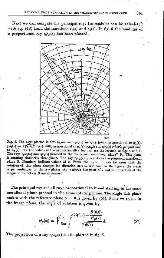
Next we can compute the principal ray. Its modulus can be calculatedwith eq. (48) from the functions T!(Z) and T2(Z). In fig. 6 the modulus ofa proportional ray TOTp(Z) has been plotted.
67103
Fig. 5. The rays plotted in this figure are rOw1{z) - rOrl{z)citp(z), proportional to lCl{Z);qt02{Z) = 2VBr/cF r2{z) eitp(z), proportional to w2{z); rowp{z) = rorp{z) eiep(~), proportionalto wp{z). For the values of the proportionality factors, see the legends to figs 4 and 6.The rays rOwl{z) and QlC2{Z)proceed in the "reference meridional plane" R. This planeis rotating clockwise throughout. The ray rowp{z) proceeds in the principalmeridionalplane P. Numbers indicate values of z; From the figure it can be seen that therotation of this plane changes its direction at z = 4-0 cm. In the figure thé s-axisis perpendicular to the x.y-plane; the positive direction of z and the direction of themagnetic induction B are downward.
The principal ray and all rays proportional to it and starting in the samemeridional plane proceed in the same rotating plane. The angle 'this planemakes with the reference plane y = 0 is given by (46). For Z = Zi, i.e, inthe image plane, the angle of rotation is given by
B(O,O)
Y- ziB(Oz)---e 'T2p(Z)ep(Zi) = - r - rxr: dz.
8m ij l !1i(z)
The projection of a ray TOWp(Z) is also plotted in fig. 5.
(57)

342 J. C. FRANCKEN and R. DORRESTEIN
DiscussionAs already stated in section 2, the ray T2(Z) determines the location
of the image planes. More than one image may be formed if this rayintersects the axis within the magnetie-field region and this field is strongenough to turn the ray back towards the axis. In the following we shallconfine the discussion to the case where there is only one image.
r('{)~ m)
8.5
2.
V5
V
,/V 1'0 rp(Z)
/0
;"
i,...- i--"
r-
3.0
2.
1.5
I.
.... 1'0(J.5
oo 2 4 6 8 10 12 14 16 18-Z(IO-am)
67104
Fig. 6. The principal ray is the path of an electron emitted with zero velocity at unit dis-tance from the axis. It is a ray with C =1= 0; so it does not intersect the axis and proceeds
, in the rotating principal meridional plane. From the principal ray a proportional ray hasbeen derived with TO = 6,24.10-4 m, This is plotted in the above figure and has, of course,the same shape as the principal ray. It forms the axis of the electron pencil emitted fromthe point TO' The converging action of the magnetic field (c.f. section 3) can be noticedbetween z = 1·5 and z = 4 cm.
'The ray T1(Z) determines the magnification of the image. This can beseen fr~m figs 4 and 5, but it is also. immediately clear from eq. (35b).For z = 0 we have T2 (z) = 0, and T1(Z) = 1, so that
u(O) = TO' (58)
0, so that
U(Zi) = ToTl (Zi) .
The, magnification M is therefore given by
M = u(Zi) = TOT1(Zi) = T1(Zi).- u(O) TO
(59)
(60)
It is well known that the magnification of the image in the magneticimage iconoscope depends on the length and position of the focusing coil,

PARAXIAL IJllAGE FORIIIATION IN THE "MAGNETIC" IMAGE ICONOSCOPE 343
all other quantities being 'given. The curve for the function rl(z) in fig. 4suggests that its initial slope r~o should have a great influence on the mag-nification. This slope can be computed by differentiating the expression(24) with respect to z and putting z = 0 and b = 0 (flat cathode). Substi-tuting for h from (19) we get
, e B2(O,O)rIO = - 4m F
It can easily be derived that this slope is given by the ratio of the initialradial forces (equal to - (e2f4m) B2(O,O), according to eqs (1) and (8)for z = 0 being the sum of the magnetic force and the centrifugal action)to the axial electrostatic force (eF).
It will be underst~od, though, that the magnification M is not solelydetermined by (61), but that the shape and strength of the focusingfields have also influence on it. Therefore the ray rl(z) is not a straightpath but rather a curved one.
Generally speaking it may be concluded, however, that fields with agreater value of B(O,O) are apt to form images with greater magnificationthan fields where the magnetic induction at the cathode is relativelysmall. Or, the shorter the effective magnetic field, the greater the magni-fication of the image. .
From eq. (21) a relation between the solutions rl(z) and r2(z) can bederived 6): .
(62a)
The constant of integration A can be computed by substituting the quan-tities at the cathode:
r20 = 0 , rIO = 1 ,
cp'/·(z) r~o= lim F'/·z'/,'. l>/ •.= lF'/ •.=+0
We then findA = -iF'/ •. (62b)
The relation (62a) becomes
cp'/·(z) h(z) r~(z) - rI(z) r~(z)~= -iF'/ •. (62c)
In the image plane, z = Zi, we have
r2(zi) = 0 and rI(zi) = M,'
so that from (62c) we have, " F 'I.
M r~(zi) = t (CP-(Zi») • (62d)
(61)

344 J. C. FRANCKEN and R. DORRESTEIN
The magnification can therefore also be computed from the final slopeof the imaging ray. In the computed case the values of M, calculated inboth ways, were 5·41 and 5·39 respectively.
Next we shall consider the principal ray. As rays proportional to thisray represent the axes of the imaging pencils, this is of special interest.From fig. 4 it is seen that the rotation of this ray changes its direction, arather unusual fact in magnetic imaging. The reason for this can easily beseen from eq. (46):'
1/-;- fZ 1 ( 11(0,0))ep(z) = V Sm 0 iq>(e) B(O,e) - Tim de. (46)
In "conventional" magnetic lenses B(O,O) is zero and the rotation isalways in the same direction. In our case the integrand of (46) is zero atz = 0, since here Tp(Z) = 1 and B(O,z) = B(O,O). Owing to the divergingaction of the electrostatic field, Tp(Z) increases rapidly and 11(O,z) decreasesonly slowly in the cathode region. Therefore the integrand of (46) willbecome positive and at first the rotation will be clockwise (if, as wasassumed, the direction of B(O,z) is the direction of the positive z-axis],
Qualitatively we have the following picture. The 'magnetic-inductionlines and electrostatic-field lines are both perpendicular to the (flat)cathode. So the electron (which is emitted without initial velocity) isaccelerated in a direction perpendicular to the cathode. At first no magneticforce is exerted on this electron. As a consequence of radial electrostaticforces the electron path soon tends to diverge, so that this will interseetinduction lines (fig. 7a). The result is a clockwise rotation due to the(primary) Lorentz force.
67105 'a b
Fig. 7. Orientation of velocity vector and magnetic-induction vector.
As a result of the tangential velocity thus acquired the electron willbe subjected to' a secondary radial, convergent, Lorentz force given by
. . e2 ~ ,11(O,O)~FL = -11(O,z) e ToTpep = -B(O,z) - TOTp 11(O,z) ---. (63)2m Tp2
This force is opposed by a diverging centrifugal force given by
• e2 ~ 11(0,0)~2Fe = m ToTpep2 = - TOTp 11(O,z) - -- •4m Tp~ .(64)

PARA..'CIAL IMAGE FORMATION IN THE "lIIAGNETIC" IMAGE ICONOSCOPE 345
The ratio of these forces is given by
Fe ~ 1 B(O,O) ~FL = - t (1- Tp2 B(O,z)S'
Hence, as long the Lorentz force is directed towards the axis, it is greaterthan the centrifugal force.
The net result of these forces is in this case a convergent force opposingthe electrostatic radial force. This converging action can clearly he seenin fig. 5 hetween z = 1.5.10-2 and z = 4.10-2. After some time the inductionlines diverge rather strongly and the angle hetween these lines and the elec-"tron velocity changes its sign (fig. 7h). The primary Lorentz force conse-quently changes its direction and the rotation will he slowed down and itultimately hecomes counier-clockwise. In eq. (46) this means that theintegrand will now he negative, owing to the small value of B(O,z). Thesecondary Lorentz force, given hy (63), will now he directed outward andthe electron path will again he diverging. The diverging action of themagnetic forces will then he reinforced hy the centrifugal action, given by(64). In this region the electrostatic forces are negligible.In the field-free region near the image plane, there are neither magnetic
nor electric forces, hut there is still a centrifugal action, given hy (64),with- B(O,z) set zero. The meridional plane containing the principal raycontinues to rotate. This, of course, is a property of all rays with C =1= 0,as is clear from eq. (8).According to the expressions (35c), for Z = Zi there is a relation hetween
the rotation of the principal ray and that of the reference meridionalplane, In our case this relation takes the form
Thus the rotation of the image, employing (56), is given hy
. Y-;- f"i B(O,z) ,ep(Zi) = - /_dz-n.
8m 0 1 lP(z).In our case the integral is smaller than n, so that the rotation of the imageis counter-clockwise. This contrasts with purely magnetic lenses, whereunder these conditions it would he clockwise. For these lenses the rotationof the image is given hy
e(Zi) = VI e f"i B(O,z) dz,8m lP
o
(65)
(66)
(67)

346 J. C. FRANCKEN and R. DORRESTEIN
and therefore it is solely determined by the integral of B(O,z). In our case(c.f. (67)) the distribution of this function along the s-axis is ofimportance,since it is multiplied hy the function rp-'/·(z) ..
Experimental check
The theoretical results discussed in the previous section could he checkedqualitatively hy experiments. More quantitative experiments and measure-ments are in preparation. They will prohahly he the subject of a latercommunication.
Eindhoven, December 1950
REFERENCES
1) P. Schagen, H. Bruining and J. C. Francken, The image iconoscope, a tel~visionpick-up tube, to appear in Philips tech. Rev.
2) H. lams, G. K. Morton and V. K. Zworykin, The image iconoscope, Proc. Inst.Radio Engrs 27, 541-547, 1939.
3) V. K. Zworykin a.o., Electron optics and the electron microscope, Wiley, New York,1945.
') E. Brüche and O. Scherzer, Geometrische Elektronenoptik, Springer, Berlin, 1934.ó) J. Picht, Einführung in die Theorie der Elektronenoptik, Barth, Leipzig, 1939.6) V. E. Cosslett, Introduction to electron optics, Clarendon Press, Oxford, 1946.7) S. Bertram, Calculation ofaxially symmetric fields, J. appl. Phys.13, 496-502,1942.8) M. van Ments and J. B. Le Poole, Numerical computation ofthe constantsofmag-
netic electron lenses, Appl. sci, Res. BI, 3-16, 1947. .