Embed Size (px)
Citation preview

50
Parallel Operation of DC Generators: In a dc power plant, power isusually supplied from several generators of small ratings connected inparallel instead of from one large generator. This is due to the followingreasons:(i) Continuity of service: If a single large generator is used in the powerplant, then in case of its breakdown, the whole plant will be shut down.However, if power is supplied from a number of small units operating inparallel, then in case of failure of one unit, the continuity of supply can bemaintained by other healthy units.(ii) Efficiency: Generators run most efficiently when loaded to their ratedcapacity. Therefore, when load demand on power plant decreases, one ormore generators can be shut down and the remaining units can beefficiently loaded.(iii) Maintenance and repair: Generators generally require routine-maintenance and repair. Therefore, if generators are operated in parallel,the routine or emergency operations can be performed by isolating theaffected generator while load is being supplied by other units. This leadsto both safety and economy.(iv) Increasing plant capacity: In the modern world of increasingpopulation, the use of electricity is continuously increasing. When addedcapacity is required, the new unit can be simply paralleled with the oldunits.(v) Non-availability of single large unit: In many situations, a single unitof desired large capacity may not be available. In that case a number ofsmaller units can be operated in parallel to meet the load requirement.Generally a single large unit is more expensive.Connecting Shunt Generators in Parallel: The generators in a powerplant are connected in parallel through bus-bars. The bus-bars are heavythick copper bars and they act as +ve and -ve terminals. The positiveterminals of the generators are .connected to the +ve side of bus-bars andnegative terminals to the negative side of bus-bars. Fig. (1) shows shuntgenerator 1 connected to the bus-bars and supplying load. When the loadon the power plant increases beyond the capacity of this generator, thesecond shunt generator 2 is connected in parallel with the first to meet theincreased load demand. The procedure for paralleling generator 2 withgenerator 1 is as under:(i) The prime mover of generator 2 is brought up to the rated speed. Nowswitch S4 in the field circuit of the generator 2 is closed.(ii) Next circuit breaker CB-2 is closed and the excitation of generator 2is adjusted till it generates voltage equal to the bus-bars voltage. This isindicated by voltmeter V2.(iii) Now the generator 2 is ready to be paralleled with generator 1. Themain switch S3 is closed, thus putting generator 2 in parallel with

51
generator 1. Note that generator 2 is not supplying any load because itsgenerated emf is equal to bus-bars voltage. The generator is said to be“floating” (i.e. not supplying any load) on the bus-bars.
Figure(1)
(iv) If generator 2 is to deliver any current, then its generated voltage Eshould be greater than the bus-bars voltage V. In that case, currentsupplied by it is I = (E - V)/Ra where Ra is the resistance of the armaturecircuit. By increasing the field current (and hence induced emf E), thegenerator 2 can be made to supply proper amount of load.(v) The load may be shifted from one shunt generator to another merelyby adjusting the field excitation. Thus if generator 1 is to be shut down,the whole load can be shifted onto generator 2 provided it has thecapacity to supply that load. In that case, reduce the current supplied bygenerator 1 to zero (This will be indicated by ammeter A1) open C.B.-1and then open the main switch S1.Load Sharing: The load sharing between shunt generators in parallel canbe easily regulated because of their drooping characteristics. The loadmay be shifted from one generator to another merely by adjusting thefield excitation. Let us discuss the load sharing of two generators whichhave unequal no-load voltages. Let E1, E2 = no-load voltages of the twogenerators R1, R2 = their armature resistancesV = common terminal voltage (Bus-bars voltage). Then
1
11 R
VEI and
2
22 R
VEI
Thus current output of the generators depends upon the values of E1 andE2. These values may be changed by field rheostats. The commonterminal voltage (or bus-bars voltage) will depend upon (i) the emfs ofindividual generators and (ii) the total load current supplied. It isgenerally desired to keep the busbars voltage constant. This can be

52
achieved by adjusting the field excitations of the generators operating inparallel.Compound Generators in Parallel: Under-compounded generators alsooperate satisfactorily in parallel but over compounded generators will notoperate satisfactorily unless their series fields are paralleled. This isachieved by connecting two negative brushes together as shown in Fig.(2) (i). The conductor used to connect these brushes is generally calledequalizer bar. Suppose that an attempt is made to operate the twogenerators in parallel without an equalizer bar. If, for any reason, thecurrent supplied by generator 1 increases slightly, the current in its seriesfield will increase and raise the generated voltage. This will causegenerator 1 to take more load. Since total load supplied to the system isconstant, the current in generator 2 must decrease and as a result its seriesfield is weakened. Since this effect is cumulative, the generator 1 willtake the entire load and drive generator 2 as a motor. After machine 2changes from a generator to a motor, the current in the shunt field willremain in the same direction, but the current in the armature and seriesfield will reverse. Thus the magnetizing action, of the series field opposesthat of the shunt field. As the current taken by the machine 2 increases,the demagnetizing action of series field becomes greater and the resultantfield becomes weaker. The resultant field will finally become zero and atthat time machine 2 will be short circuited machine 1, opening thebreaker of either or both machines.
Figure (2)
When the equalizer bar is used, a stabilizing action exists and neithermachine tends to take all the load. To consider this, suppose that currentdelivered by generator 1 increases. The increased current will not onlypass through the series field of generator 1 but also through the equalizerbar and series field of generator 2. Therefore, the voltage of both themachines increases and the generator 2 will take a part of the load.
53
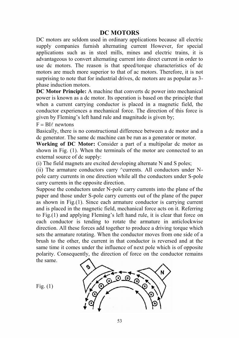
DC MOTORSDC motors are seldom used in ordinary applications because all electricsupply companies furnish alternating current However, for specialapplications such as in steel mills, mines and electric trains, it isadvantageous to convert alternating current into direct current in order touse dc motors. The reason is that speed/torque characteristics of dcmotors are much more superior to that of ac motors. Therefore, it is notsurprising to note that for industrial drives, dc motors are as popular as 3-phase induction motors.DC Motor Principle: A machine that converts dc power into mechanicalpower is known as a dc motor. Its operation is based on the principle thatwhen a current carrying conductor is placed in a magnetic field, theconductor experiences a mechanical force. The direction of this force isgiven by Fleming’s left hand rule and magnitude is given by;F BInewtonsBasically, there is no constructional difference between a dc motor and adc generator. The same dc machine can be run as a generator or motor.Working of DC Motor: Consider a part of a multipolar dc motor asshown in Fig. (1). When the terminals of the motor are connected to anexternal source of dc supply:(i) The field magnets are excited developing alternate N and S poles;(ii) The armature conductors carry ^currents. All conductors under N-pole carry currents in one direction while all the conductors under S-polecarry currents in the opposite direction.Suppose the conductors under N-pole carry currents into the plane of thepaper and those under S-pole carry currents out of the plane of the paperas shown in Fig.(1). Since each armature conductor is carrying currentand is placed in the magnetic field, mechanical force acts on it. Referringto Fig.(1) and applying Fleming’s left hand rule, it is clear that force oneach conductor is tending to rotate the armature in anticlockwisedirection. All these forces add together to produce a driving torque whichsets the armature rotating. When the conductor moves from one side of abrush to the other, the current in that conductor is reversed and at thesame time it comes under the influence of next pole which is of oppositepolarity. Consequently, the direction of force on the conductor remainsthe same.
Fig. (1)

54
Back or Counter EMF: When the armature of a dc motor rotates underthe influence of the driving torque, the armature conductors movethrough the magnetic field and hence emf is induced in them as in agenerator The induced emf acts in opposite direction to the appliedvoltage V(Lenz’s law) and in known as back or counter emf E. The backemf E(= P ZN/60 A) is always less than the applied voltage V, althoughthis difference is small when the motor is running under normalconditions.If Ra is the armature circuit resistance, then,
aa R
EVI
Since V and Ra are usually fixed, the value of E will determine thecurrent drawn by the motor. If the speed of the motor is high, then backemf (E=PZN/60A) is large and hence the motor will draw less armaturecurrent and vice-versa.
Figure (2)
Significance of Back EMF: The presence of back emf makes the dcmotor a self-regulating machine i.e., it makes the motor to draw as mucharmature current as is just sufficient to develop the torque required by theload.
When the motor is running on no load, small torque is required toovercome the friction and windage losses. Therefore, the armaturecurrent Ia is small and the back emf is nearly equal to the appliedvoltage.
If the motor is loaded, the first effect is to cause the armature toslow down and hence the back emf E falls. The decreased back emfallows a larger current to flow through the armature and largercurrent means increased driving torque. Thus, the driving torqueincreases as the motor slows down. The motor will stop slowingdown when the armature current is just sufficient to produce theincreased torque required by the load.

55
If the load on the motor is decreased, the driving torque ismomentarily in excess of the requirement so that armature isaccelerated. As the armature speed increases, the back emf E alsoincreases and causes the armature current Ia to decrease. The motorwill stop accelerating when the armature current is just sufficient toproduce the reduced torque required by the load. It follows;therefore, that back emf in a dc motor regulates the flow ofarmature current i.e., it automatically changes the armature currentto meet the load requirement.
Voltage and power Equations of DC Motor: Let in a dc motor,
Figure (3)
V = applied voltageE = back e.m.f.Ra = armature resistanceIa = armature currentVEIaRa. By multiplying this equation by la, we get, VIa EIa I2
aRaThis is known as power equation of the dc motor.VIa = electric power supplied to armature (armature input)EIa = power developed by armature (armature output)Ia
2 Ra = electric power wasted in armature (armature Cu loss)Thus out of the armature input, a small portion (about 5%) is wasted as aIa
2Ra and the remaining portion EIa is converted into mechanical powerwithin the armature.Types of DC Motors: Like generators, there are three types of dc motorscharacterized by the connections of field winding in relation to thearmature:(i) Shunt-wound motor(ii) Series-wound motor(iii) Compound-wound motorArmature Torque of DC Motor: Consider a pulley of radius r meteracted upon by a circumferential force of F Newton which causes it torotate at N r.p.m.

56
Then torque T = F r Newton-meter (N.m)Work done by this force in one revolution =Forcedistance=F2 r JoulePower developed = F 2 r N Joule/second or Watt (N in r.p.s unit)
= (F r) 2 N Watt2 N = Angular velocity ωin radian/secondPower developed = T ωwatt or P = T ωWattMoreover, if N is in r.p.m., thenω= 2 N/60 rad/s
TNp 60
2
Armature Torque of a Motor: Let Ta be the torque developed by thearmature of a motor running at N r.p.m. If Ta is in N.m, thenPower developed = Ta 2 N/60 watt ...(i), Electrical powerconverted into mechanical power in the armature=EIa watt ...(ii)Equating (i) and (ii), we get Ta 2 N/60 = EIa ...(iii)
Since E = ZNP/60A volt, we have
APZIT aa
21 N.m
Ta Ia. In the case of a series motor, is directly proportional to Ia (before
saturation) because field windings carry full armature current.Ta I2a
For shunt motors, is practically constant.Ta Ia
Shaft Torque (Tsh): The whole of the armature torque, as calculatedabove, is not available for doing useful work, because a certainpercentage of it is required for supplying iron and friction losses in themotor. The torque which is available for doing useful work is known asshaft torque Tsh. It is so called because it is available at the shaft:
60/2 NPT out
sh N.m
The difference (TaTsh) is known as lost torque and is due to iron andfriction losses of the motor.

57
Speed of a DC Motor:EVIaRa and
AZNPE
60
Then
)(60)( aaaa RIVKPZARIVN
where K 60A/PZ
EKN or
EN
Therefore, in a dc motor, speed is directly proportional to back emf E andinversely proportional to flux per pole .If a dc motor has initial valuesof speed, flux per pole and back emf as and E1 respectively and thecorresponding final values are N2, 2 and E2, then,
1
11
EN and2
22
EN then2
1
1
2
1
2
EE
NN
(i) For a shunt motor, flux practically remains constant so that 1 = 2.
1
2
1
2
EE
NN
(ii) For a series motor, Ia prior to saturation.
2
1
1
2
1
2
a
a
II
EE
NN
where
Ia1 = initial armature currentIa2 = final armature currentSpeed Regulation: The speed regulation of a motor is the change inspeed from full-load to no-loud and is expressed as a percentage of thespeed at full-load i.e.Speed regulation 100
NNNo % where
N0 = No - load .speedN = Full - load speedArmature Reaction in DC Motors: As in a dc generator, armaturereaction also occurs in a dc motor. This is expected because when currentflows through the armature conductors of a dc motor, it produces flux(armature flux) which lets on the flux produced by the main poles. For amotor with the same polarity and direction of rotation as is for generator,the direction of armature reaction field is reversed.(i) In a generator, the armature current flows in the direction of theinduced emf (i.e. generated emf E) whereas in a motor, the armaturecurrent flows against the induced emf (i.e. back emf E). Therefore, itshould be expected that for the same direction of rotation and fieldpolarity, the armature flux of the motor will be in the opposite direction tothat of the generator. Hence instead of the main flux being distorted in thedirection of rotation as in a generator, it is distorted opposite to thedirection of rotation. We can conclude that: Armature reaction in a dc

58
generator weakens the flux at leading pole tips and strengthens the flux attrailing pole tips while the armature reaction in a dc motor produces theopposite effect.(ii) In case of a dc generator, with brushes along G.N.A. and nocommutating poles used, the brushes must be shifted in the direction ofrotation (forward lead) for satisfactory commutation. However, in case ofa dc motor, the brushes are given a negative lead i.e., they are shiftedagainst the direction of rotation.(iii) By using commutating poles (compoles), a dc machine can beoperated with fixed brush positions for all conditions of load. Sincecommutating poles windings carry the armature current, then, when amachine changes from generator to motor (with consequent reversal ofcurrent), the polarities of commutating poles must be of opposite sign.Therefore, in a dc motor, the commutating poles must have the samepolarity as the main poles directly back of them. This is the opposite ofthe corresponding relation in a dc generator.Commutation in DC Motors: Since the armature of a motor is the sameas that of a generator, the current from the supply line must divide andpass through the paths of the armature windings. In order to produceunidirectional force (or torque) on the armature conductors of a motor,the conductors under any pole must carry the current in the samedirection at all times.
In this case, the current flows away from the observer in the conductorsunder the N-pole and towards the observer in the conductors under the S-pole. Therefore, when a conductor moves from the influence of N-pole tothat of S-pole, the direction of current in the conductor must be reversed.This is termed as commutation. The function of the commutator and thebrush gear in a dc motor is to cause the reversal of current in a conductoras it moves from one side of a brush to the other. For good commutation,the following points may be noted:

59
(i) If a motor does not have commutating poles (compoles), the brushesmust be given a negative lead i.e., they must be shifted from G.N.A.against the direction of rotation of, the motor.(ii) By using interpoles, a dc motor can be operated with fixed brushpositions for all conditions of load. For a dc motor, the commutatingpoles must have the same polarity as the main poles directly back ofthem. This is the opposite of the corresponding relation in a dc generator.A dc machine may be used as a motor or a generator without changingthe commutating poles connections. When the operation of a dc machinechanges from generator to motor, the direction of the armature currentreverses. Since commutating poles winding carries armature current, thepolarity of commutating pole reverses automatically to the correctpolarity.Losses in a DC Motor: The losses occurring in a dc motor are the sameas in a dc generator. These are:(i) copper losses and Iron losses or magnetic losses(ii) Mechanical lossesAs in a generator, these losses cause (a) an increase of machinetemperature and (b) Reduction in the efficiency of the dc motor.The following points may be noted:(i) Apart from armature Cu loss, field Cu loss and brush contact loss, Culosses also occur in interpoles (commutating poles) and compensatingwindings. Since these windings carry armature current (Ia),Loss in interpole winding = I2
a x Resistance of interpole windingLoss in compensating winding =I2
a x Resistance of compensating winding(ii) Since dc machines (generators or motors) are generally operated atconstant flux density and constant speed, the iron losses are nearlyconstant.(iii) The mechanical losses (i.e. friction and windage) vary as the cube ofthe speed of rotation of the dc machine (generator or motor). Since dcmachines are generally operated at constant speed, mechanical losses areconsidered to be constant.Efficiency of a DC Motor: Like a dc generator, the efficiency of a dcmotor is the ratio of output power to the input power i.e.
As for a generator, the efficiency of a dc motor will be maximum when:Variable losses = Constant lossesTherefore, the efficiency curve of a dc motor is similar in shape to that ofa dc generator.A - B = Copper lossesB - C = Iron and friction losses

60
Overall efficiency, ηc = C/AElectrical efficiency, ηe = B/AMechanical efficiency, ηm = C/B
DC Motor Characteristics: There are three principal types of dc motors:shunt motors, series motors and compound motors. The performance of adc motor can be judged from its characteristic curves known as motorcharacteristics; following are the three important characteristics of a dcmotor:(i) Torque and Armature current characteristic (Ta/Ia): It is known aselectrical characteristic of the motor.(ii) Speed and armature current characteristic (N/Ia): It is very importantcharacteristic as it is often the deciding factor in the selection of themotor for a particular application.(iii) Speed and torque characteristic (N/Ta): It is also known asmechanical characteristic.
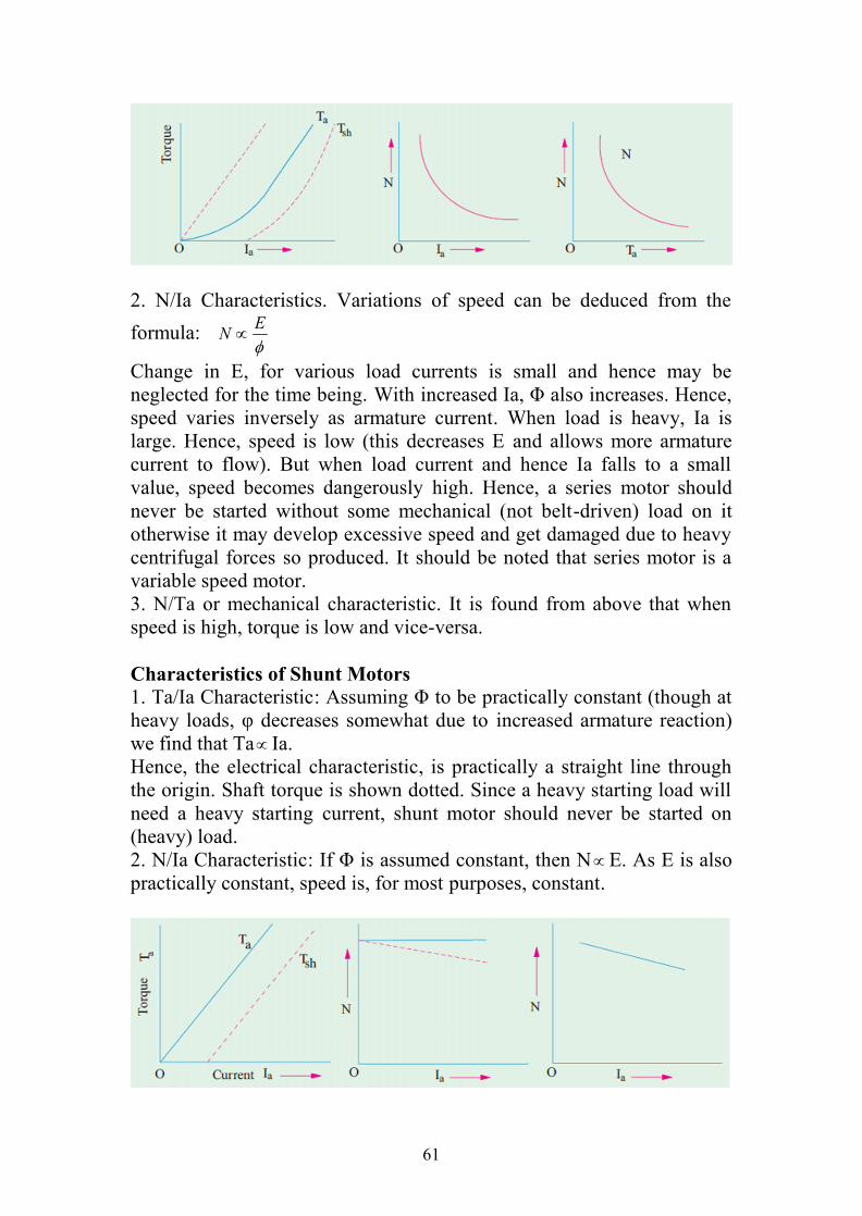
Characteristics of Series Motors1. Ta/Ia Characteristic. We have seen that TaΦIa. In this case, as fieldwindings also carry the armature current, Φ Ia up to the point ofmagnetic saturation. Hence, before saturation,TaΦIa and Ta I2aAt light loads, Ia and hence Φ is small. But as Ia increases, Ta increasesas the square of the current. Hence, Ta/Ia curve is a parabola. Aftersaturation, Φ is almost independent of Ia hence Ta Ia only. So thecharacteristic becomes a straight line. The shaft torque Tsh is less thanarmature torque due to stray losses. It is shown dotted in the figure. So weconclude that (prior to magnetic saturation) on heavy loads, a seriesmotor exerts a torque proportional to the square of armature current.Hence, in cases where huge starting torque is required for acceleratingheavy masses quickly as in hoists and electric trains etc., series motorsare used.
61
2. N/Ia Characteristics. Variations of speed can be deduced from theformula:
EN
Change in E, for various load currents is small and hence may beneglected for the time being. With increased Ia, Φ also increases. Hence,speed varies inversely as armature current. When load is heavy, Ia islarge. Hence, speed is low (this decreases E and allows more armaturecurrent to flow). But when load current and hence Ia falls to a smallvalue, speed becomes dangerously high. Hence, a series motor shouldnever be started without some mechanical (not belt-driven) load on itotherwise it may develop excessive speed and get damaged due to heavycentrifugal forces so produced. It should be noted that series motor is avariable speed motor.3. N/Ta or mechanical characteristic. It is found from above that whenspeed is high, torque is low and vice-versa.
Characteristics of Shunt Motors1. Ta/Ia Characteristic: Assuming Φ to be practically constant (though atheavy loads, φ decreases somewhat due to increased armature reaction)we find that Ta Ia.Hence, the electrical characteristic, is practically a straight line throughthe origin. Shaft torque is shown dotted. Since a heavy starting load willneed a heavy starting current, shunt motor should never be started on(heavy) load.2. N/Ia Characteristic: If Φ is assumed constant, then NE. As E is alsopractically constant, speed is, for most purposes, constant.
62
But strictly speaking, both E and Φ decrease with increasing load.However, E decreases slightly more than φ so that on the whole, there issome decrease in speed. The drop varies from 5 to 15% of full-loadspeed, being dependent on saturation, armature reaction and brushposition. Hence, the actual speed curve is slightly drooping as shown bythe dotted line in the figure. But, for all practical purposes, shunt motor istaken as a constant-speed motor. Because there is no appreciable changein the speed of a shunt motor from no-load to full load, it may beconnected to loads which are totally and suddenly thrown off without anyfear of excessive speed resulting. Due to the constancy of their speed,shunt motors are suitable for driving shafting, machine tools, lathes,wood-working machines and for all other purposes where anapproximately constant speed is required.3. N/Ta Characteristic can be deduced from (1) and (2) above.
Compound Motors: These motors have both series and shunt windings.If series excitation helps the shunt excitation i.e. series flux is in the samedirection; then the motor is said to be cummulatively compounded. If onthe other hand, series field opposes the shunt field, then the motor is saidto be differentially compounded. The characteristics of such motors lie inbetween those of shunt and series motors.(a) Cumulative-compound Motors: Such machines are used where seriescharacteristics are required and where, in addition, the load is likely to beremoved totally such as in some types of coal cutting machines or fordriving heavy machine tools which have to take sudden cuts quite often.Due to shunt windings, speed will not become excessively high but due toseries windings, it will be able to take heavy loads. In conjunction withfly-wheel (functioning as load equalizer), it is employed where there aresudden temporary loads as in rolling mills. The fly-wheel supplies itsstored kinetic energy when motor slows down due to sudden heavy load.And when due to the removal of load motor speeds up, it gathers up itskinetic energy. Compound-wound motors have greatest application withloads that require high starting torques or pulsating loads (because suchmotors smooth out the energy demand required of a pulsating load). Theyare used to drive electric shovels, metal-stamping machines, reciprocatingpumps, hoists and compressors etc.(b) Differential-compound Motors: Since series field opposes the shuntfield, the flux is decreased as load is applied to the motor. This results inthe motor speed remaining almost constant or even increasing withincrease in load (because, NE/(Φ). Due to this reason, there is adecrease in the rate at which the motor torque increases with load. Suchmotors are not in common use. But because they can be designed to givean accurately constant speed under all conditions, they find limited

63
application for experimental and research work. One of the biggestdrawback of such a motor is that due to weakening of flux with increasesin load, there is a tendency towards speed instability and motor runningaway unless designed properly.