Embed Size (px)
Citation preview

PLG11_CATM_STD_AND_HLP_EFF_ALL_8522201_01_016.DOCX
PARALLEL LIFT GROUP Manual Pins & Hydraulic Locking Pins (HLP) HENKE MODEL: PLG11, PLG11 HLP, CAT M For CATERPILLAR 12H, 120H-163H, 12M, 120M-160M, and 14M Series Graders
PARTS BOOK AND INSTALLATION MANUAL SERIAL NUMBER __________________ VERSION 1.5, MAY 2016
HENKE MANUFACTURING CORPORATION
MANUFACTURERS OF SNOW REMOVAL EQUIPMENT FOR 95 YEARS 3070 WILSON AVE. LEAVENWORTH, KS 66048 PHONE (913)682-9000 FAX (913)682-0300
WEBSITE ADDRESS: WWW.HENKEMFG.COM EMAIL: [email protected]
Manual Locking Pins Hydraulic Locking Pins (HLP)

PLG11_CATM_STD_AND_HLP_EFF_ALL_8522201_01_016.DOCX Page 3 of 37
Introduction Thank you for your purchase of a Henke Lift Group for your snow fighting needs. Please read this manual in its entirety before installing or operating the lift group. If any items appear to be missing, or if you need assistance of any kind, please call Henke Manufacturing at (913) 682-9000 or toll-free at (888) 682-9010. NOTE – All references to “Left” or “Right” in this manual refer to the view from the driver’s position.
Table of Contents Introduction ........................................................................................................... 3
Safety Section ..................................................................................... (Section 1) 6
Maintenance ........................................................................................................... 7
Loose Ship Hardware .......................................................................................... 10
Hydraulic Figures, Tables, and Schematics For PLP11, Manual and Hydraulic
Locking Pins (HLP), Grader to Lift Cylinder and BH, No Diverter ................... 16
Hydraulic Figures, Tables, and Schematics For PLP11, Hydraulic Locking Pin
Plumbing, No Diverter ......................................................................................... 20
Hydraulic Figures, Tables, and Schematics For PLP11, HLP, With Diverter .. 26
Wear Parts ............................................................................................................ 33
Henke Warranty ................................................................................................... 36
Dealer Warranty Procedure ................................................................................ 37

PLG11_CATM_STD_AND_HLP_EFF_ALL_8522201_01_016.DOCX Page 4 of 37
FIGURES FIGURE 1 – Henke Parallel Lift Group 11, CAT M ..................................... COVER
FIGURE 2-1 – PLG11 ........................................................................................... 11
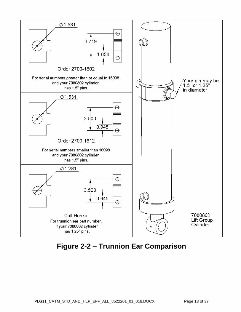
FIGURE 2-2 – Trunnion Ear Comparison ........................................................... 13
FIGURE 2-3 – Manual and Hydraulic Pins Comparison ................................... 14
FIGURE 3-1 – Hose Routing, for PLG11, Motor Grader to Cylinder and
Bulkhead Plates (No Diverter) ....................................................... 17
FIGURE 3-2 – Lift Group Bulkhead Routing (LEFT & RIGHT), (No Diverter) .. 18
FIGURE 3-3 – PLG11, Hydraulic Schematic for Lift Cylinder (No Diverter) .... 19
FIGURE 3-4 – PLG11, Hydraulic Schematic for Henke Bulkhead Auxiliary
Ports, Manual and Hydraulic Pins (No Diverter) .......................... 20
FIGURE 3-5 – Hydraulic Locking Pins Hose Routing from CAT Auxiliary #2
(No Diverter) .................................................................................. 21
FIGURE 3-6 – Hydraulic Locking Pins Hose Routing from Henke Bulkhead #1
(No Diverter) ................................................................................... 22
FIGURE 3-7 – Hose Routing from Auxiliary to Diverter.................................... 27
FIGURE 3-8 – Left Side Bracket and Diverter Hardware .................................. 28
FIGURE 3-9 – Right Side Bracket Hardware & Hose Routing Diverter to Lift
Cylinder .......................................................................................... 29
FIGURE 3-10 – Hose Routing from Diverter to Hydraulic Locking Pins ......... 30
PLG11_CATM_STD_AND_HLP_EFF_ALL_8522201_01_016.DOCX Page 5 of 37
TABLES TABLE 2-1 – Loose Ship Hardware .................................................................... 10
TABLE 2-2 – Parallel Lift Group 11, CAT M, Parts List ................................ 12
TABLE 2-3 – Manual and Hydraulic Pins Comparison, Parts List .................. 14
TABLE 3-1 – Hydraulic Hose Kit for CAT M PLG11, Manual Locking Pins (No
Diverter) .......................................................................................... 23
TABLE 3-2 – Hydraulic Hose Kit for CAT M PLG11, Hydraulic Locking Pins
(HLP) (No Diverter) ......................................................................... 23
TABLE 3-3 – Auxiliary Supply Hydraulic Fittings With or Without Hydraulic
Locking Pins, and With or Without Diverter ................................ 24
TABLE 3-4 – Hydraulic Hose Kit for CAT M PLG11 With Hydraulic Locking
Pins and Diverter ........................................................................... 31
TABLE 4-1 – Cutting Edges ................................................................................ 33
TABLE 4-2 – Cutting Edge Hardware ................................................................. 34
TABLE 4-3 – Henke Curb Guard & Wear Guards .............................................. 35

Safety Section 1-1
© 2015 Alamo Group Inc.
SAFETY SECTION

SAFETYS
AF
ET
Y
GENERAL SAFETY INSTRUCTIONS AND PRACTICES
A careful operator is the best operator. Safety is of primary importance to the manufacturer and should be tothe owner/operator. Most accidents can be avoided by being aware of your equipment, your surroundings,and observing certain precautions. The first section of this manual includes a list of Safety Messages that, iffollowed, will help protect the operator and bystanders from injury or death. Read and understand theseSafety Messages before assembling, operating or servicing this Implement. This equipment should only beoperated by those persons who have read the manual, who are responsible and trained, and who know howto do so responsibly.
The Safety Alert Symbol combined with a Signal Word, as seen below, is used throughout thismanual and on decals which are attached to the equipment. The Safety Alert Symbol means:“ATTENTION! BECOME ALERT! YOUR SAFETY IS INVOLVED!” The Symbol and Signal Wordare intended to warn the owner/operator of impending hazards and the degree of possible injuryfaced when operating this equipment.
Indicates an imminently hazardous situation that, if not avoided, WILL result in DEATH ORVERY SERIOUS INJURY.
Indicates an imminently hazardous situation that, if not avoided, COULD result in DEATHOR SERIOUS INJURY.
Indicates an imminently hazardous situation that, if not avoided, MAY result in MINORINJURY.
Identifies special instructions or procedures that, if not strictly observed, could result indamage to, or destruction of the machine, attachments or the environment.
NOTE: Identifies points of particular interest for more efficient and convenient operation or repair.
READ, UNDERSTAND, and FOLLOW the following Safety Messages. Serious injury ordeath may occur unless care is taken to follow the warnings and instructions stated in thisManual and in the Safety Messages on the implement. Always follow the instruction in thismanual and use good common sense to avoid hazards.
Pictographs are used throughout this manual to help bring your visual attention to safety issues.
NOTE: If you want a translation of this safety section in one of the following Languages, please contact:Translations at 1502 E. Walnut Street Seguin, TX 78155; Fax: (830) 372-9529; Safety Section Translationsare available in Spanish, Portuguese, French, German, Russian. P-GS-01
Practice all usual and customary safe working precautions and above all---remember safety is up to YOU. Only YOU can prevent serious injury or deathfrom unsafe practices.
Plow Safety Section 1-2
© 2015 Alamo Group Inc.

SAFETYS
AF
ET
Y
OPERATOR SAFETY
TO AVOID SERIOUS INJURY OR DEATH DO THE FOLLOWING:
• READ, UNDERSTAND and FOLLOW Operator's Manual instructions, Warnings and Safety Messages.• WEAR SAFETY GLASSES, safety shoes, hard hat and gloves when operating or repairing equipment• DO NOT WEAR loose clothing or jewelry to avoid rotating parts entanglement injury.• DO NOT USE DRUGS or ALCOHOL before or while operating equipment. • DO NOT ALLOW anyone to operate equipment under the influence of drug or alcohol.• CONSULT medical professional for medication impairment side effects.• STAY ALERT, prolonged operation can cause fatigue; STOP and REST.
GENERAL OPERATING SAFETYVISIBILITY CONDITIONS WHEN PLOWING:• OPERATE IN DAYLIGHT or with lights that give at least 100 yards clear visibility.• BE ABLE TO SEE and identify passersby, steep slopes, ditches, drop-offs, overhead obstructions, power lines, debris and
foreign objects.GROUND SPEED WHEN PLOWING:• NORMAL SPEED range is between 5 to 45mph.• ADJUST plowing SPEED for terrain conditions.• REDUCE plowing SPEED when near steep slopes, ditches, drop-offs, overhead obstructions, and power lines.SAFETY SIGNS AND WARNING DECALS:• REPLACE missing, damaged or unreadable safety signs immediately. SHIELDING:• NEVER remove protective shields and guards! NEVER modify or cut protective shields or guards!PROLONGED OPERATION IN COLD WEATHER:• May Cause Operator Hypothermia affecting safe operation of implement.• Wear appropriate clothing and take scheduled breaks. • If possible shut down equipment, exit cab, and warm body in properly heated area. • NEVER operate implement in fatigued or impaired mental state.COMMUNICATION:• Verbal Communication can be difficult and dangerous near implement.• Operating instructions and directions should be made prior to starting implement.• If communication is necessary completely shutdown and exit implement.• NEVER allow anyone to approach implement while in operation. RIDING PASSENGERS:• Never allow passengers whose presence distracts from safe operation or transporting of implement• If passengers presence is needed, passenger must be seated securely and belted in passenger seat. • DO NOT allow passenger in any other area of implement, other than in passenger seat during operation or transport. CHEMICAL HAZARD• Wear appropriate PPE when handling chemicals. Refer to Chemical MSDS sheets.• Always wear safety glasses, shield, gloves, and apron.• Wear Respirator when required. PN P-OS-01
Plow Safety Section 1-3
© 2015 Alamo Group Inc.
SAFETYS
AF
ET
Y
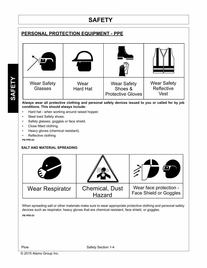
PERSONAL PROTECTION EQUIPMENT - PPE
SALT AND MATERIAL SPREADING
Always wear all protective clothing and personal safety devices issued to you or called for by jobconditions. This should always include:
• Hard hat - when working around raised hopper.
• Steel toed Safety shoes.
• Safety glasses, goggles or face shield.
• Close fitted clothing.
• Heavy gloves (chemical resistant).
• Reflective clothing.PN PPE-02
When spreading salt or other materials make sure to wear appropriate protective clothing and personal safetydevices such as respirator, heavy gloves that are chemical resistant, face shield, or goggles.
PN PPE-03
Plow Safety Section 1-4
© 2015 Alamo Group Inc.

SAFETYS
AF
ET
Y
CRUSHING HAZARDS
TO AVOID SERIOUS INJURY OR DEATH FROM FALLING OFF VEHICLE, EQUIPMENTRUN OVER, ROLLOVER AND CRUSHING BY FALLING IMPLEMENT:
CRUSHING BY FALLING from EQUIPMENT
• ALWAYS BUCKLE UP seat belt when operating vehicle and equipment.• ONLY OPERATE vehicle and equipment while seated in vehicle seat.• STOP VEHICLE ENGINE, place transmission into park, engage parking brake, and remove key.
TO AVOID FALLING OFF OR BEING CRUSHED BY EQUIPMENT
• Use extreme care when climbing onto vehicle or attachment. Also always use three point contact using available handles and steps on vehicle or power unit while exiting.
• Removing the vehicle key is a lockout procedure to prevent a coworker from starting the vehicle while someone is working on attachment.
• Never Attempt to mount the vehicle or attachment while unit is moving.• Do not remove safety latches or chains on stowed equipment unless stowed equipment is being held in
place by active hydraulic power or other secure method to prevent if from dropping.
TO AVOID CHILDREN FALLING OFF OR BEING CRUSHED BY EQUIPMENT:
• NEVER ALLOW children to play on or around vehicle or equipment. PN P-CH-01
Plow Safety Section 1-5
© 2015 Alamo Group Inc.

SAFETYS
AF
ET
Y
CONNECTING OR DISCONNECTING IMPLEMENT SAFETY
TO AVOID SERIOUS INJURY OR DEATH FROM BEING CRUSHED BY VEHICLE ORATTACHEMENT:
WHEN ATTACHING UNIT TO VEHICLE:
• DO NOT ALLOW BYSTANDERS between vehicle and plow.• Keep hands and body clear of the attachment and the attachment mounts.
BEFORE connecting and disconnecting Plow Components:
• STOP VEHICLE ENGINE, place transmission into park, engage parking brake, and remove key.
WHEN connecting and disconnecting Plow:
• DO NOT crawl or walk under the Plow when in storage position.• Make sure Plow is properly attached to vehicle and the retaining pins, hardware, chains, and cables
securely lock the Attachment into position.• DO NOT attempt to disconnect trip edge by hand. Trip devices are spring loaded and sudden movement
can occur resulting in serious injuries. PN P-CD-01
Plow Safety Section 1-6
© 2015 Alamo Group Inc.

SAFETYS
AF
ET
Y
RUN OVER HAZARDS
TO AVOID SERIOUS INJURY OR DEATH FROM FALLING OFF VEHICLE OREQUIPMENT RUN OVER:
• ONLY start vehicle while seated in vehicle seat.
• ALWAYS BUCKLE UP seat belt when operating vehicle and equipment.
• ONLY OPERATE vehicle and equipment while seated in vehicle seat.
• NEVER ALLOW RIDERS on vehicle or implement.
• Ensure area is clear around vehicle and equipment before starting or operating equipment.
WHEN MOUNTING AND DISMOUNTING VEHICLE:
• ONLY mount or dismount when vehicle and moving parts are stopped.
• STOP ENGINE, engage parking brake, lower implement, allow all moving parts to stop and remove key before dismounting from vehicle. PN P-RO-01
Plow Safety Section 1-7
© 2015 Alamo Group Inc.

SAFETYS
AF
ET
Y
THROWN OBJECTS HAZARDS
PLOW IS CAPABLE OF PROPELLING OBJECTS UP TO 75 FEET.
TO AVOID SERIOUS INJURY TO OPERATOR OR PASSERSBY FROM THROWN OBJECTS:
• KEEP bystanders 100 feet away• Stop plowing if bystanders are within the potential thrown area.
STOP PLOWING IF PASSERSBY ARE WITHIN 100 FEET:
• Make sure no bystander, animal or obstruction such as vehicle, building or street sign are within the width of plow.
• Avoid hitting solid, or oversized objects. Objects could become airborne and cause personal injury or damage to equipment.
• Remove or mark any foreign objects that could be propelled or cause damage to plow.
PLOW OPERATION:
• DO NOT exceed Plow’s rated plowing speed.• Ensure plow is equipped with warning signals to alert motorist and pedestrians. • Always turn on all safety lights and flashers when operating plow. PN P-TO-01
Plow Safety Section 1-8
© 2015 Alamo Group Inc.

SAFETYS
AF
ET
Y
BLADE CONTACT HAZARDS
HIGH PRESSURE OIL LEAK HAZARD
KEEP AWAY FROM BLADE TO AVOID SERIOUS INJURY OR DEATH FROM BLADE CONTACT:
• STAY AWAY and KEEP HANDS, FEET and BODY AWAY from plow blade and parts until engine has come to a complete stop.
• DO NOT put hands or feet under plow blade.• STOP, disengage power and ensure plow is resting and supported on blocks before adjusting plow blade.• STOP, LOOK, and LISTEN before approaching the plow to make sure engine has stopped. PN P-BC-01
TO AVOID SERIOUS INJURY OR DEATH FROM HIGH PRESSURE HYDRAULIC OIL LEAKSPENERATING SKIN:
• DO NOT OPERATE equipment with oil or fuel leaks.• KEEP all hydraulic hoses, lines and connections in GOOD CONDITION and TIGHT before applying system
pressure. • RELIEVE HYDRAULIC PRESSURE before disconnecting lines or working on the system. • REMOVE and replace hose if you suspect it leaks. Have dealer test it for leaks.HIGH PRESSURE FLUID LEAKS CAN BE INVISIBLE.WHEN CHECKING FOR HYDRAULIC LEAKS AND WORKING AROUND HYDRAULIC SYSTEMS:• ALWAYS WEAR safety glasses and impenetrable gloves. • USE paper or cardboard to search for leaks.• DO NOT USE hands or body parts to search for leak.• KEEP hands and body AWAY from pin holes and nozzles ejecting hydraulic fluid.• Injected Hydraulic fluid may cause gangrene if not surgically removed immediately by a doctor familiar with this form
of injury. PN HP01
Plow Safety Section 1-9
© 2015 Alamo Group Inc.

SAFETYS
AF
ET
Y
TRANSPORTING HAZARDS
TO AVOID SERIOUS INJURY AND DEATH WHEN OPERATING OR TRANSPORTINGEQUIPMENT:
• KEEP transport speed to the posted speed limit to maintain control of equipment.• REDUCE SPEED on inclines, on turns and in poor plowing conditions.• DO NOT TOW with trucks or other vehicles use a flatbed vehicle to transport.• FOLLOW all local traffic regulations.BEFORE TRANSPORTING OR TOWING IMPLEMENT:• Ensure equipment has been stowed in transport position and secured with safety latches or chains.VEHICLE INSPECTION:• CHECK steering and braking for proper operation and in good condition. • CHECK that transport pins are engaged.• CHECK reflectors and warning lights for proper operation and visibility behind unit.• ROUTINELY inspect the equipment’s headlights, brake lights, backup lights, and turn signal lights for
operational condition.• Always turn on all safety lights and flashers when you operate the implement. • CHECK that your driving vision is not impaired by cab while seated in vehicle seat.• ADJUST your operating position, mirrors, and implement transport for clear vision for traveling and traffic
conditions.DETERMINE STOPPING CHARACTERISTICS OF VEHICLE AND IMPLEMENT FOR TRANSPORTINGOR OPERATING:• With added weight and severe weather conditions stopping distances may increase.• Only operate at speeds that you can properly control equipment.DETERMINE MAXIMUM TURNING SPEED BEFORE OPERATING ON ROADS OR UNEVEN GROUND:• TEST equipment in slowly increasing speed on turns to determine it can be operated at higher speeds.• USE REDUCED turning speeds on sharp turns to avoid equipment turning over.• Center of gravity may have shifted with equipment installation.WHEN OPERATING OR TRANSPORTING EQUIPMENT:• Always WEAR SEAT BELT when operating or transporting spreader.• USE low speeds to avoid overturn while operating or transporting.• USE low speeds and gradual steering on curves, hills, rough or uneven surfaces and on wet roads. • Use extreme caution when operating the equipment in traffic.• Use all equipped warning signals to alert motorist and pedestrians of the presence of the equipment• DO NOT leave piled material on roadway. Material can be a hazard to other motorist. TO AVOID SERIOUS INJURY OR DEATH FROM ELECTRICAL CONTACT WHEN WORKING AROUNDELECTRICAL POWER LINES AND UTILITY LINES:• INSPECT area for overhead power lines, obstructions, cables and utility lines, municipal, or other type
structure.• KEEP Plow 10 feet or greater distance from all power lines and overhead obstructions.• DO NOT allow Plow to contact with any utility, municipal, or type of structures and obstructions. P-TH-01
Plow Safety Section 1-10
© 2015 Alamo Group Inc.

SAFETYS
AF
ET
Y
HAZARDS WITH MAINTENANCE OF IMPLEMENT
AVOID SERIOUS INJURY OR DEATH FROM COMPONENT FAILURE BY KEEPINGIMPLEMENT IN GOOD OPERATING CONDITION BY PERFORMING PROPERSERVICE, REPAIRS, AND MAINTENANCE.
BEFORE PERFORMING SERVICE, REPAIRS, AND MAINTENANCE ON THE IMPLEMENT:
SECURE EQUIPMENT FOR SERVICE
BLOCK OUT POTENTIAL ENERGY HAZARDS; Rotating Parts, Raised Components, HydraulicPressure.
• STOP ENGINE, engage parking brake, and allow all moving parts to stop and remove key beforedismounting from vehicle seat.
• Securely block up raised equipment. Use large blocks on soft or wet soil.• PUSH and PULL Remote Hydraulic Cylinder lever to relieve hydraulic pressure.• DISCONNECT IMPLEMENT Hydraulic HOSES from vehicle.WEAR SAFETY GLASSES, PROTECTIVE GLOVES and follow SAFETY PROCEDURES whenperforming service, repairs, and maintenance on the implement:
• Always WEAR protective GLOVES when handling chemicals or worn component with sharp edges.• Always WEAR GLOVES and SAFETY GLASSES when servicing components.• AVOID CONTACT with hot hydraulic oil or chemicals.• SECURELY support or BLOCK UP raised implement, framework, and lifted components before working
underneath equipment.• STOP any implement movements and SHUT-OFF VEHICLE engine before doing any work procedures.• USE step ladder or raised stands to reach high equipment areas inaccessible from ground.• ENSURE good footing by standing on solid flat surfaces when getting on implement to perform work.• FOLLOW manufacturer's instructions in handling oils, solvents, cleansers, and other chemical agents.• DO NOT change any factory-set hydraulic calibrations to avoid component or equipment failures.• DO NOT modify or alter implement, functions or components.• DO NOT WELD or straighten broken, cracked or broken blade PN P-HM-01
Plow Safety Section 1-11
© 2015 Alamo Group Inc.

SAFETYS
AF
ET
Y
HAZARDS WITH MAINTENANCE OF IMPLEMENT CONTINUED
AVOID SERIOUS INJURY OR DEATH FROM COMPONENT FAILURE BY KEEPINGIMPLEMENT IN GOOD OPERATING CONDITION BY PERFORMING PROPERSERVICE, REPAIRS AND MAINTENANCE.
PERFORM SERVICE, REPAIRS, LUBRICATION AND MAINTENANCE OUTLINED IN IMPLEMENTMAINTENANCE SECTION:• INSPECT before each use for loose fasteners, worn or broken parts, leaky or loose fittings, missing or
broken cotter keys and washers on pins, and all moving parts for wear.• REPLACE Blade or any worn or broken parts with authorized service parts.• LUBRICATE unit as specified by lubrication schedule.• Ensure all fluid levels are properly filled.• NEVER lubricate, adjust or remove material while it is running or in motion.• TORQUE all bolts and nuts as specified.• Check tire conditions.• Never remove debris or unclog jams from spring pressurized pinch points by hand.• Avoid contact with recently used equipment that may still be hot. • Ensure the scheduled maintenance is up to date. • Do Not modify or alter equipment/plow.• Do Not leave snow plow unattended while snow plow wing is in an unsecured raised position. • Do Not crawl or walk under unsecured raised equipment. SAFETY SHIELDS, GUARDS AND SAFETY DEVICES INSPECTION:• KEEP all Steel Guards, Bands, and Skid Shoes in place and in good condition.• Maintain Safety Signs and Decals in good readable condition.• REPLACE any missing, broken or worn safety shields, guards and safety devices.• Engine Exhaust, some of its constituents, and certain vehicle components contain or emit chemicals
known to the state of California to cause cancer, birth defects or other reproductive harm.• Battery posts, terminals and related accessories contain lead and lead compounds, chemicals known to
the state of California to cause cancer, birth defects or other reproductive harm. PN P-HM-02
Plow Safety Section 1-12
© 2015 Alamo Group Inc.
SAFETYS
AF
ET
Y
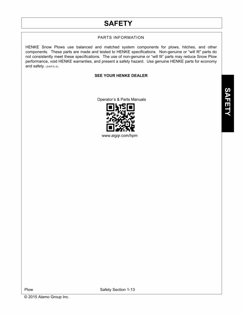
PARTS INFORMATION
HENKE Snow Plows use balanced and matched system components for plows, hitches, and othercomponents. These parts are made and tested to HENKE specifications. Non-genuine or “will fit" parts donot consistently meet these specifications. The use of non-genuine or “will fit” parts may reduce Snow Plowperformance, void HENKE warranties, and present a safety hazard. Use genuine HENKE parts for economyand safety. (SNPG-6)
SEE YOUR HENKE DEALER
Plow Safety Section 1-13
© 2015 Alamo Group Inc.

Version 1.0, 03/29/2010
DECALS - PLG Lift Groups.doc
PLG – Parallel Lift Group
Kit Revision Notes:

DECALS
TRUCK HITCH – TILT & FD Safety Section 1-14
PLG – Parallel Lift Group
Henke Part No.
Qty. Description
7331003 1 Use genuine Henke replacement parts7331004 1 Secure body with blocks7331005 1 Stop Engine Stay clear of moving parts
7331006 1Do not use hands to check for oil leaks
High Pressure oil leak-injection
7331007 1Read and understand operator's manualIf you cannot read English get assistance
7331010 1 Keep Clear, Pinch Point
7330012 1 Serial Number Tag7300047 1 Product Manual Canister7300048 1 Plug - Product Manual Canister
Other Attachments and Decals
Use the following decals from sheet 7332006-010.
NOTE: Use all decals listed above from sheet 7332006-010 and discard remaining decals
Instructions: Follow these instructions to position the above items to your Henke product for safety and professional appearance. Apply on clean surfaces only. They should be properly applied and kept in good condition. If a decal is worn out, torn, or otherwise defaced, call us for an immediate replacement at 1-913-682-9000, or 1-888-682-9010.

DECALS
TRUCK HITCH – TILT & FD Safety Section 1-15
1. Position 7331007, 7331010, 7331005, & 7330012 as shown on Driver’s Side.
2. Position Canister 73300047 as shown below Serial Number Plate in preferred location or positioned in alternate location on lower arm centered to prevent interference when Lift Group is raised or lowered.
CANISTER 7300047 Alternate Location
DECALS
TRUCK HITCH – TILT & FD Safety Section 1-16
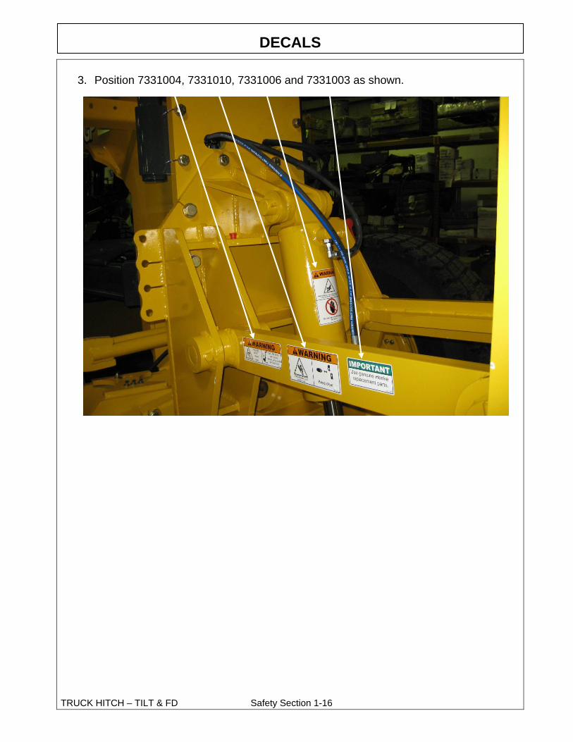
3. Position 7331004, 7331010, 7331006 and 7331003 as shown.

PLG11_CATM_STD_AND_HLP_EFF_ALL_8522201_01_016.DOCX Page 7 of 37
IN SEASON MAINTENANCE
Snow removal equipment must be cared for and maintained regularly. Daily or pre-route inspection and maintenance are necessary. Failure to do so may affect efficiency and safety.
A visual inspection must be carried out after every 8 hours of operation. Look for
damaged components, bends, cracked welds or hydraulic leaks. REPAIR IMMEDIATELY! It is recommended to re-torque all bolts after the first 8 hours of use and to regularly check for loosened or missing fasteners. Replace any damaged or missing fasteners immediately.
Because of the environment in which snow equipment is expected to operate, hydraulic lines, fasteners, wearable or replaceable items and warning decals may become damaged by snow, ice and road debris. These items must be inspected daily and replaced if necessary to avoid equipment damage or personal injury.
Lubrication of moving parts is of the utmost importance. Exposure to snow, ice, salt and road debris will wash away lubrication quickly and it may be necessary to inspect and reapply lubrication more than once a day.
PLG11_CATM_STD_AND_HLP_EFF_ALL_8522201_01_016.DOCX Page 8 of 37
GROUND ENGAGING COMPONENTS
CUTTING EDGES & GUARDS: Replace any broken cutting edges, unevenly or excessively worn cutting edges, and broken or worn wear guards.
RUNNING GEAR: Replace broken, worn, or missing running gear shoes, and any damaged adjuster leg components. Grease internal threads and sliding members (it’s best to disassemble and grease directly; zerks aren’t as effective at greasing these areas).
HARDWARE: Replace missing or broken bolts. Proper torque is important! Use
grade 8 plow bolts for steel cutting edges.
HYDRAULICS
HOSES: Plug or cap any QC fittings or any open hose ends. Inspect hoses for any
leaks or potential leaks. Secure hoses with hose clamps.
CYLINDERS: Check for leaks, and any chrome rod dents or scratches. Apply a light coat of oil or grease on exposed rod surfaces.
FRAME AND MOLDBOARD
JOINTS: Check pins, bushings, and pivot bolts for wear. Make sure all keepers
are in place. Make sure shear bolts and pins are same as original equipment (usually grade 2). Some drivers don’t like replacing shear pins and will install grade 8 replacements to avoid replacing during a storm. These items are designed to shear to protect the driver and the equipment. CHECK WELDMENTS FOR CRACKS.
CABLE AND SHEAVES (IF APPLICABLE)
CABLE: Check cable thoroughly for fraying, kinks, and abnormal wear. Make sure
cable is properly routed and seated in all sheaves. Verify that cable clamps have the proper torque and are in the correct orientation and spacing. Cable shall be checked prior to each use or after every 8 hours, whichever comes first.
SHEAVES: Verify that sheave, bushings and retaining pins are in good condition and adequately greased. Make sure that sheaves, bushings and pins do not have any abnormal wear and rotate without restriction.
REPLACE WORN OR BROKEN PARTS FOUND BY ABOVE INSPECTIONS
END OF SEASON MAINTENANCE

PLG11_CATM_STD_AND_HLP_EFF_ALL_8522201_01_016.DOCX Page 9 of 37
<<THIS PAGE IS INTENTIONALLY LEFT BLANK>>

PLG11_CATM_STD_AND_HLP_EFF_ALL_8522201_01_016.DOCX Page 10 of 37
Qty. Part No. Description
14 7020082 Hex Capscrew, 3/4-10 X 3.5 GR. 8
28 7040007 Flat Washer, 3/4 Hardened, SAE
14 7030013 Nut, 3/4-10 GR. 8
TABLE 2-1 – Loose Ship Hardware

PLG11_CATM_STD_AND_HLP_EFF_ALL_8522201_01_016.DOCX Page 11 of 37
FIGURE 2-1 – Parallel Lift Group 11

PLG11_CATM_STD_AND_HLP_EFF_ALL_8522201_01_016.DOCX Page 12 of 37
Item No. Qty. Part No. Description
1 2 279-0595 Upper Pin Assembly, PLG11
2 1
279-0590
279-0607
Backplate Assembly, PLG11, CAT 12H, 120-163H,
12M, 120M-160M
Backplate Assembly, PLG11, CAT 14M
3 2 279-0594 Pin Assembly, PLG11
4 1 279-0591 Lower Arm Assembly
5 9 7040005 Flat Washer, 1/2 Hardened, USS
6 9 7020136 Hex Capscrew, 1/2-13 x 1.0
7 1 279-0613 Cylinder Pin Assembly, PLG11
8 1 7050115 Safety Snap Pin, 3/8 x 2.5
9 1 279-0624 Drift Lock Pin, PLG11
10 1 7080802 Hydraulic Cylinder
11 4 7020059 Hex Capscrew, 1/2-13 x 4.5 GR.8
12 4 7040042 Flat Washer, 1/2 Hardened, SAE
13 1 279-0592 Upper Arm Assembly
14
14
12
7020082
7020267
Hex Capscrew, 3/4-10 x 3.50 GR.8, CAT 12H, 120H-
1663H, 12M, 120M-160M,14M
Hex Capscrew, 1-8 x 4.50 GR.8, CAT 14M
15
28
24
7040007
7040013
Flat Washer, 3/4" Hardened, SAE, CAT 12H, 120H-
1663H, 12M, 120M-160M,14M
Flat Washer, 1" Hardened, SAE, CAT 14M
16
14
12
7030013
7030016
Nut, 3/4-10 GR.8, CAT 12H, 120H-1663H, 12M,
120M-160M,14M
Nut, 1-8 GR.8, CAT 14M
17 2 2700-1602 Trunion Ear
18 1 279-0593 Balderson Style Hitch - Male
TABLE 2-2 – Parallel Lift Group 11, Parts List
PLG11_CATM_STD_AND_HLP_EFF_ALL_8522201_01_016.DOCX Page 13 of 37
Figure 2-2 – Trunnion Ear Comparison

PLG11_CATM_STD_AND_HLP_EFF_ALL_8522201_01_016.DOCX Page 14 of 37
Item No. Qty. Part No. Description
1 1 Reference Balderson Style Hitch - Male
2 2 139-0831 Hitch Pin Assembly
3 2 7050096 Safety Snap Pin, 1/4 x 2.25
4 2 279-0429 Pin Assembly
5 1 7080507 Hydraulic Cylinder for Locking Pins
6 2 7020301 Set Screw, 3/8-16 X 1.5, Nylon Pellet
7 2 7020060 Hex Capscrew, 5/8-11 X 2.00 GR. 8
8 1 2700-1553 Stop Plate, Hydraulic Locking Pin
9 2 7030084 Toplock Nut, 5/8-11 GR. C
FIGURE 2-3 – Manual and Hydraulic Pins Comparison
TABLE 2-3 – Manual and Hydraulic Pins Comparison, Parts List

PLG11_CATM_STD_AND_HLP_EFF_ALL_8522201_01_016.DOCX Page 15 of 37
The Following Three Section Contains
Hydraulic Figures, Tables, and Schematics For:
PLG11
o Parallel Lift Group 11 with Manual Locking Pins
PLG11 HLP o Parallel Lift Group 11 with Hydraulic Locking Pins
PLG11 HLP + DIV o Parallel Lift Group 11 with Hydraulic Locking Pins
and Diverter (HLP + DIV)

PLG11_CATM_STD_AND_HLP_EFF_ALL_8522201_01_016.DOCX Page 16 of 37
The Following Pages Include Hydraulic
Figures, Tables, and Schematics For:
From Cat Motor Grader
To Lift Cylinder and Bulkhead Plates.
Parallel Lift Group 11 (PLG11)
No Diverter
(Manual and Hydraulic Locking Pins)
PLG11_CATM_STD_AND_HLP_EFF_ALL_8522201_01_016.DOCX Page 17 of 37
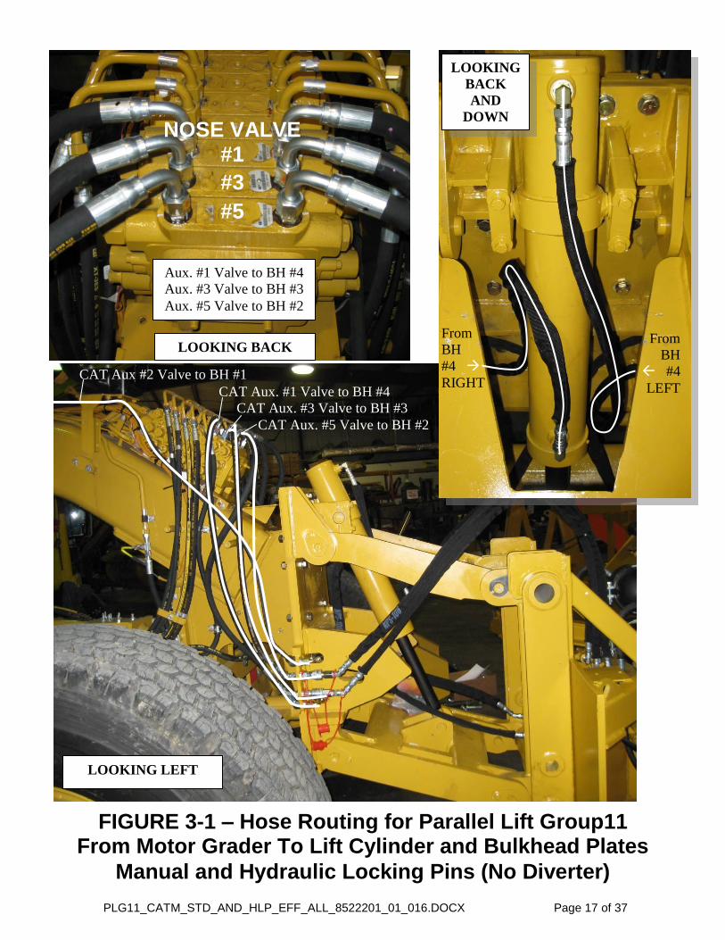
FIGURE 3-1 – Hose Routing for Parallel Lift Group11 From Motor Grader To Lift Cylinder and Bulkhead Plates
Manual and Hydraulic Locking Pins (No Diverter)
CAT Aux. #1 Valve to BH #4
CAT Aux. #3 Valve to BH #3
CAT Aux. #5 Valve to BH #2
CAT Aux #2 Valve to BH #1
LOOKING LEFT
LOOKING
BACK
AND
DOWN
From
BH
#4
RIGHT
From
BH
#4
LEFT
LOOKING BACK
NOSE VALVE #1
#3
#5
Aux. #1 Valve to BH #4
Aux. #3 Valve to BH #3
Aux. #5 Valve to BH #2

PLG11_CATM_STD_AND_HLP_EFF_ALL_8522201_01_016.DOCX Page 18 of 37
FIGURE 3-2 – Lift Group Bulkhead Routing, LEFT and
RIGHT, Manual and Hydraulic Locking Pins (No Diverter)
LOOKING RIGHT
FRONT
LEFT BH
1 2
3
4
LOOKING LEFT
FRONT
RIGHT BH
1 2 3
4

PLG11_CATM_STD_AND_HLP_EFF_ALL_8522201_01_016.DOCX Page 19 of 37
FROM CAT Auxiliary Valve 1: I I
CAT HOSE LEFT I
(1) 7090729 Bulkhead Fitting I
From BH Position 4 LEFT I
(1) 7110857 45” Hose I
(1) 70 0257 0 Elbow I
TO BARREL End of Lift Cylinder
CAT HOSE RIGHT I
(1) 7090729 Bulkhead Fitting I
From BH Position 4 RIGHT I
(1) 7110858 43” Hose I
(1) 70 0257 0 Elbow I
TO ROD End of Lift Cylinder
FROM CAT Auxiliary Valve 3: I
CAT HOSES LEFT & RIGHT I
(2) 7090563 Adapter I
(2) 70 0404 45 Elbow I
(2) 7090419 Bulkhead Fitting I
To BH Position 3 LEFT & RIGHT I
(2) 7090544 Quick Coupler F w/ (2) 7090405 Dust Plug
I (2) 7090521 Quick Coupler M Bleeder
(Included with Plow Hydraulic Kit)
FROM CAT Auxiliary Valve 5: I
CAT HOSES LEFT & RIGHT I
(2) 7090563 Adapter I
(2) 70 0404 45 Elbow I
(2) 7090419 Bulkhead Fitting I
To BH Position 2 LEFT & RIGHT I
(2) 7090543 Quick Coupler M w/ (2) 7090406 Dust Cap
I (2) 7090522 Quick Coupler F Bleeder
(Included with Plow Hydraulic Kit)
FIGURE 3-3 – PLG11, Hydraulic SCHEMATIC for Lift Cylinder
(No Diverter)
FIGURE 3-4 – PLG11, Hydraulic SCHEMATIC for Henke Bulkhead Auxiliary Ports
Manual and Hydraulic Locking Pins (No Diverter)

PLG11_CATM_STD_AND_HLP_EFF_ALL_8522201_01_016.DOCX Page 20 of 37
The Following Pages Include Hydraulic
Figures, Tables, and Schematics Plumbing:
From Cat Motor Grader
To Hydraulic Locking Pins.
Parallel Lift Group 11 (PLG11)
With
Hydraulic Locking Pins (HLP)
No Diverter
PLG11_CATM_STD_AND_HLP_EFF_ALL_8522201_01_016.DOCX Page 21 of 37
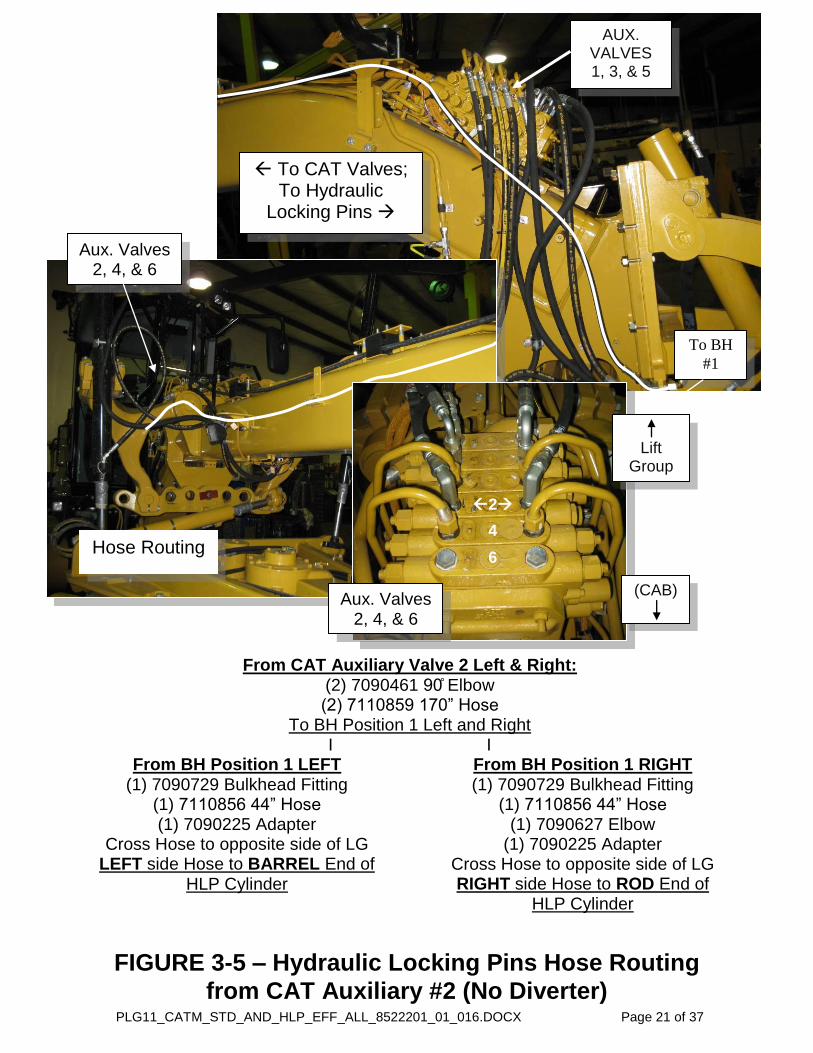
From CAT Auxiliary Valve 2 Left & Right: (2) 7090461 0 Elbow (2) 711085 170” Hose
To BH Position 1 Left and Right I I
From BH Position 1 LEFT (1) 7090729 Bulkhead Fitting
(1) 7110856 44” Hose (1) 7090225 Adapter
Cross Hose to opposite side of LG LEFT side Hose to BARREL End of
HLP Cylinder
From BH Position 1 RIGHT (1) 7090729 Bulkhead Fitting
(1) 7110856 44” Hose (1) 7090627 Elbow
(1) 7090225 Adapter Cross Hose to opposite side of LG RIGHT side Hose to ROD End of
HLP Cylinder
To CAT Valves; To Hydraulic
Locking Pins
AUX. VALVES 1, 3, & 5
FIGURE 3-5 – Hydraulic Locking Pins Hose Routing
from CAT Auxiliary #2 (No Diverter)
Hose Routing
Aux. Valves 2, 4, & 6
2
4
6
Aux. Valves 2, 4, & 6
Lift
Group
(CAB)
To BH
#1
PLG11_CATM_STD_AND_HLP_EFF_ALL_8522201_01_016.DOCX Page 22 of 37
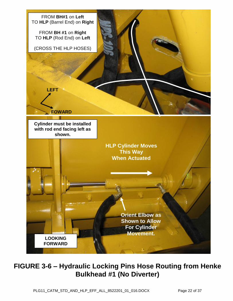
FIGURE 3-6 – Hydraulic Locking Pins Hose Routing from Henke
Bulkhead #1 (No Diverter)
HLP Cylinder Moves This Way
When Actuated
Orient Elbow as Shown to Allow
For Cylinder
Movement.
FROM BH#1 on Left TO HLP (Barrel End) on Right
FROM BH #1 on Right
TO HLP (Rod End) on Left
(CROSS THE HLP HOSES)
FOWARD
LOOKING
FORWARD
LEFT
Cylinder must be installed with rod end facing left as
shown.
PLG11_CATM_STD_AND_HLP_EFF_ALL_8522201_01_016.DOCX Page 23 of 37
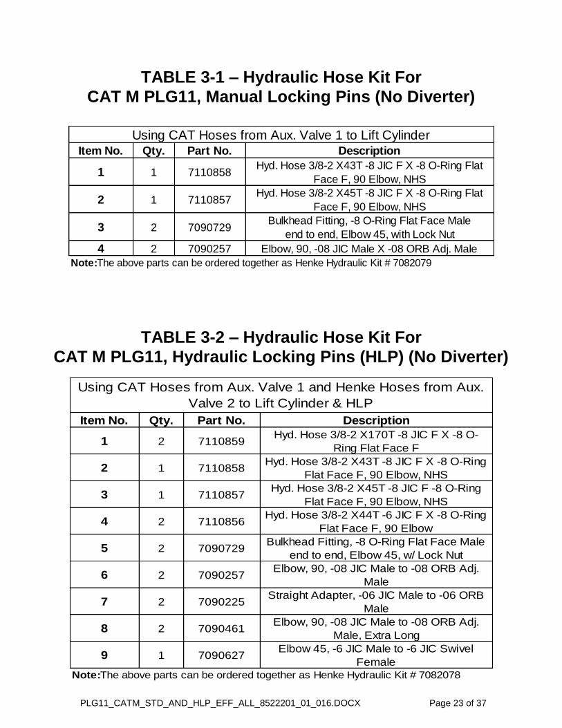
Item No. Qty. Part No. Description
1 2 7110859Hyd. Hose 3/8-2 X170T -8 JIC F X -8 O-
Ring Flat Face F
2 1 7110858Hyd. Hose 3/8-2 X43T -8 JIC F X -8 O-Ring
Flat Face F, 90 Elbow, NHS
3 1 7110857Hyd. Hose 3/8-2 X45T -8 JIC F -8 O-Ring
Flat Face F, 90 Elbow, NHS
4 2 7110856Hyd. Hose 3/8-2 X44T -6 JIC F X -8 O-Ring
Flat Face F, 90 Elbow
5 2 7090729Bulkhead Fitting, -8 O-Ring Flat Face Male
end to end, Elbow 45, w/ Lock Nut
6 2 7090257Elbow, 90, -08 JIC Male to -08 ORB Adj.
Male
7 2 7090225Straight Adapter, -06 JIC Male to -06 ORB
Male
8 2 7090461Elbow, 90, -08 JIC Male to -08 ORB Adj.
Male, Extra Long
9 1 7090627Elbow 45, -6 JIC Male to -6 JIC Swivel
Female
Note:The above parts can be ordered together as Henke Hydraulic Kit # 7082078
Using CAT Hoses from Aux. Valve 1 and Henke Hoses from Aux.
Valve 2 to Lift Cylinder & HLP
Item No. Qty. Part No. Description
1 1 7110858Hyd. Hose 3/8-2 X43T -8 JIC F X -8 O-Ring Flat
Face F, 90 Elbow, NHS
2 1 7110857Hyd. Hose 3/8-2 X45T -8 JIC F X -8 O-Ring Flat
Face F, 90 Elbow, NHS
3 2 7090729Bulkhead Fitting, -8 O-Ring Flat Face Male
end to end, Elbow 45, with Lock Nut
4 2 7090257 Elbow, 90, -08 JIC Male X -08 ORB Adj. Male
Note:The above parts can be ordered together as Henke Hydraulic Kit # 7082079
Using CAT Hoses from Aux. Valve 1 to Lift Cylinder
TABLE 3-2 – Hydraulic Hose Kit For
CAT M PLG11, Hydraulic Locking Pins (HLP) (No Diverter)
TABLE 3-1 – Hydraulic Hose Kit For
CAT M PLG11, Manual Locking Pins (No Diverter)

PLG11_CATM_STD_AND_HLP_EFF_ALL_8522201_01_016.DOCX Page 24 of 37
Item No. Qty. Part No. Description
1 2 7090563Straight Adapter, -08 ORFF Male to -08 JIC
Swivel Female
2 2 7090404Elbow, 45, -08 JIC Male to -08 JIC Swivel
Female
3 2 7090419Bulkhead Ftg, -08 ORB Male (Short End) to -
08 JIC Male
4 1 7090543 Quick Coupler Male, -8 ORB
5 1 7090544 Quick Coupler Female, -8 ORB
6 1 7090405 Dust Plug
7 1 7090406 Dust Cap
Auxiliary Supply to PLG Bulkhead From Aux. Valves 3 & 5 to
Bulkhead Positions 3 & 2 respectively
Note: The above parts can be ordered together as Henke Part # 6185240 for 1
valve section.
TABLE 3-3 – Auxiliary Supply Hydraulics Fittings With or Without Hydraulic Locking Pins, and With or Without Diverter

PLG11_CATM_STD_AND_HLP_EFF_ALL_8522201_01_016.DOCX Page 25 of 37
<<THIS PAGE IS INTENTIONALLY LEFT BLANK>>

PLG11_CATM_STD_AND_HLP_EFF_ALL_8522201_01_016.DOCX Page 26 of 37
The Following Pages Include Hydraulic
Figures, Tables, and Schematics For:
Parallel Lift Group 11 (PLG11)
With
Hydraulic Locking Pins (HLP)
And
Hydraulic Diverter (DIV)

PLG11_CATM_STD_AND_HLP_EFF_ALL_8522201_01_016.DOCX Page 27 of 37
FIGURE 3-7 – Hose Routing from Auxiliary to Diverter
From CAT Aux. #1 LEFT & RIGHT Use CAT Hoses Provided
From Aux. #1 RIGHT CAT HOSE RIGHT
7090729 Bulkhead Fitting
2700-1574 Small Bulkhead Plate
7110864 16.5” Hose
70 0 5 0 Elbow
7090014 Adapter
Rear LEFT Diverter Port
From Aux. #1 LEFT CAT HOSE LEFT
7090563 Adapter
70 0 5 0 Elbow
7090014 Adapter
Rear LEFT Diverter Port
LOOKING BACK
CAT AUX. #1
#3
#5
Aux. #1 Valve to DIVERTER
Aux. #3 Valve to BH #3
Aux. #5 Valve to BH #2
Aux. #1 Valve LEFT to
Rear of Diverter LEFT
LOOKING
RIGHT
2700-1571 Bulkhead
Plate
LOOKING
LEFT
Aux. #1 Valve RIGHT to
Rear of Diverter RIGHT
2700-1574 2700-1573 Bulkhead Plate & Base
PLG11_CATM_STD_AND_HLP_EFF_ALL_8522201_01_016.DOCX Page 28 of 37
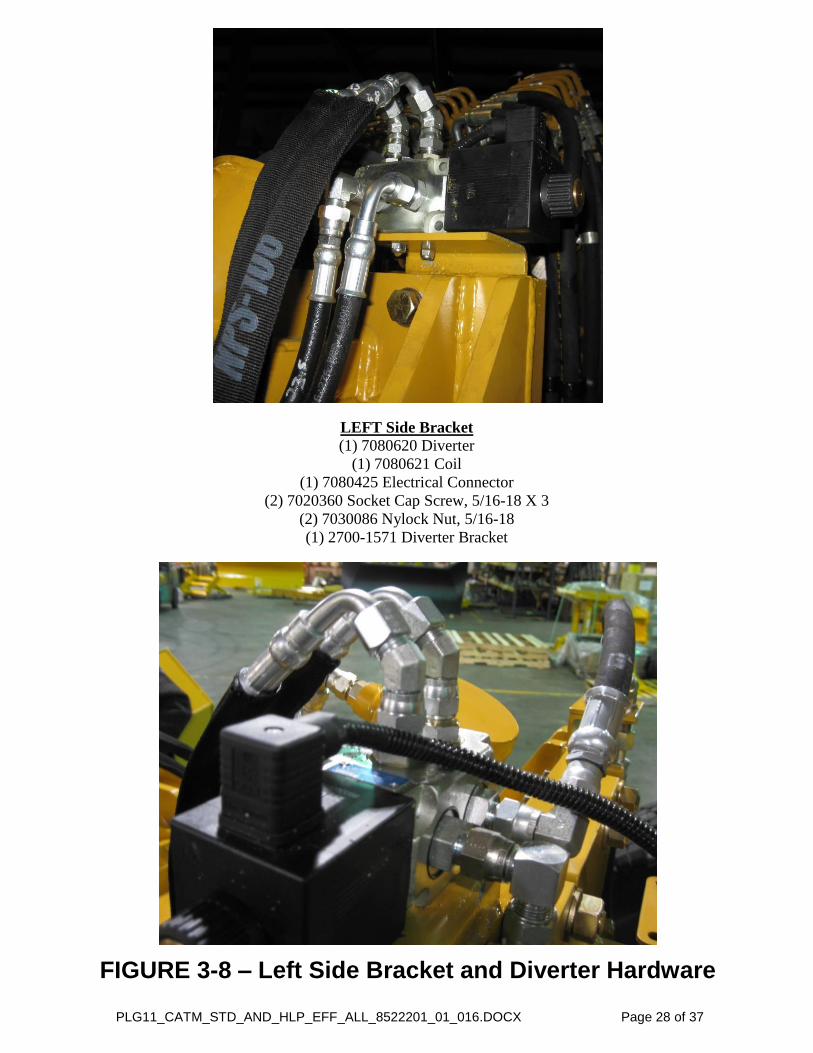
FIGURE 3-8 – Left Side Bracket and Diverter Hardware
LEFT Side Bracket
(1) 7080620 Diverter
(1) 7080621 Coil
(1) 7080425 Electrical Connector
(2) 7020360 Socket Cap Screw, 5/16-18 X 3
(2) 7030086 Nylock Nut, 5/16-18
(1) 2700-1571 Diverter Bracket

PLG11_CATM_STD_AND_HLP_EFF_ALL_8522201_01_016.DOCX Page 29 of 37
FIGURE 3-9 – Right Side Bracket Hardware and
Hose Routing from Diverter to Lift Cylinder
RIGHT Side Bracket
(1) 2700-1573 Bracket Base
(1) 2700-1574 Small Bulkhead Plate, Bolt-On
(2) 7020322 Hex Capscrew, 1/4-20 X 1 GR. 5
(2) 7030044 Nylock Nut, 1/4-20
FROM Diverter to Lift Cylinder
From RIGHT FRONT Port (1) 7090014 Adapter
(1) 7110865 8” Hose
(1) 70 0 88 0 Elbow
To ROD End of Lift Cylinder
From LEFT FRONT Port (1) 7090014 Adapter
(1) 7110861 5 ” Hose
(Wrap hose under and behind cylinder)
(1) 70 0 88 0 Elbow
To BARREL End of Lift Cylinder
From Diverter To Lift Cylinder
RIGHT Front to Rod End, Lower Port
LEFT Front to Barrel End, Upper Port
RIGHT
SIDE LEFT
SIDE
LOOKING
LEFT

PLG11_CATM_STD_AND_HLP_EFF_ALL_8522201_01_016.DOCX Page 30 of 37
LEFT SIDE
7110862
7110863
Orient Elbows as Shown to Allow
For Cylinder
Movement.
HLP Cylinder Moves This Way
When Actuated RIGHT SIDE
FIGURE 3-10 – Hose Routing from Diverter
to Hydraulic Locking Pins
FROM Diverter to HLP
From RIGHT TOP Port (1) 7090014 Adapter
(1) 70 0404 45 Elbow
(1) 711086 68” Hose
(1) 70 06 7 45 Elbow
(1) 7090225 Adapter
To ROD End of HLP Cylinder
From LEFT FRONT Port (1) 7090014 Adapter
(1) 70 0404 45 Elbow
(1) 711086 75” Hose
(1) 70 0477 0 Elbow
To BARREL End of HLP Cylinder
RIGHT
SIDE
From Diverter To HLP
TOP Right to Rod End, Left Port
TOP Left to Barrel End, Right Port
7110862
7110863 LEFT
SIDE

PLG11_CATM_STD_AND_HLP_EFF_ALL_8522201_01_016.DOCX Page 31 of 37
Item No. Qty. Part No. Description
1 1 7110865 HH 3/8-2 X28T -6 JIC F X -8 JIC F,90 Elbow
2 1 7110861 HH 3/8-2 X52T 6 JIC F X -8 JIC F, 90 Elbow
3 1 7110863 HH 3/8-2 X68T 6 JIC F X -8 JIC F, 90 Elbow
4 1 7110862 HH 3/8-2 X75T 6 JIC F X -8 JIC F, 90 Elbow
5 1 7110864 HH 1/2-2 X16.5T -8 JIC F X -8 O-Ring Flat Face F
6 6 7090014 Straight Adapter, -08 JIC Male X -10 ORB Male
7 2 7090235 Elbow, 90, -08 JIC Male X -08 JIC Swivel Female
8 2 7090388 Elbow, 90, -06 JIC Male X -08 ORB Adj. Male
9 1 7090563Straight Adapter, -08 ORFF Male X -08 JIC Swivel
Female
10 2 7090404 Elbow, 45, -08 JIC Male X -08 JIC Swivel Female
11 1 7090729Bulkhead Fitting, -8 O-Ring Flat Face Male,
end to end, Elbow 45, w/ Lock Nut
12 1 7090225 Straight Adapter, -06 JIC Male X -06 ORB Male
13 1 7090477 Elbow, 90, -06 JIC Male X -06 ORB Adj. Male
14 1 7090627 Elbow, 45, -06 JIC Male X -06 JIC Swivel Female
Note:The above parts can be ordered together as Henke Hydraulic Kit # 7082080
Using CAT Hoses from Aux. Valve 1, to Diverter,
to Lift Cylinder & HLP
TABLE 3-4 – Hydraulic Hose Kit For CAT M PLG11
with Hydraulic Locking Pins and Diverter

PLG11_CATM_STD_AND_HLP_EFF_ALL_8522201_01_016.DOCX Page 32 of 37
<<THIS PAGE IS INTENTIONALLY LEFT BLANK>>
PLG11_CATM_STD_AND_HLP_EFF_ALL_8522201_01_016.DOCX Page 33 of 37
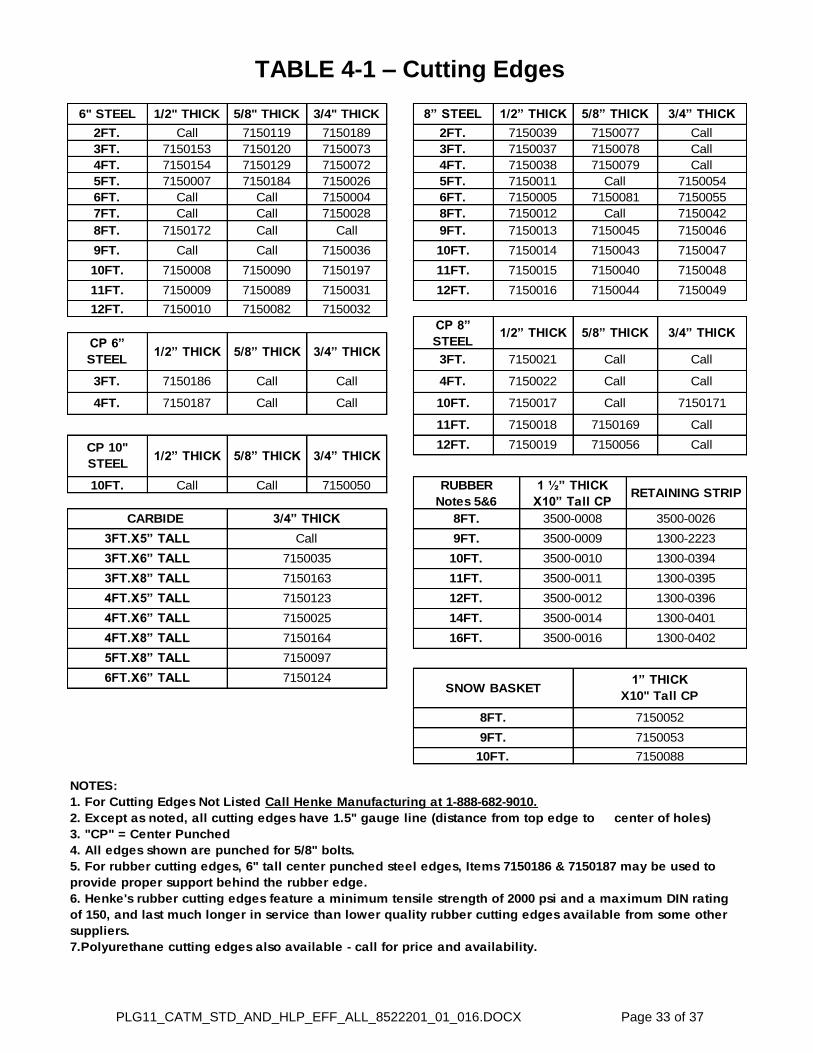
TABLE 4-1 – Cutting Edges
10FT. 7150088
SNOW BASKET1” THICK
X10" Tall CP
16FT. 3500-0016 1300-0402
12FT. 3500-0012 1300-0396
RUBBER
Notes 5&6
1 ½” THICK
X10” Tall CPRETAINING STRIP
CARBIDE 3/4” THICK
4FT.X5” TALL 7150123
4FT.X8” TALL 7150164
8FT. 3500-0008 3500-0026
9FT. 7150053
CP 8”
STEEL1/2” THICK 5/8” THICK 3/4” THICK
12FT. 7150019 7150056 Call
9FT. 7150013 7150045 71500468FT. 7150172 Call Call
11FT. 3500-0011 1300-03953FT.X8” TALL 7150163
10FT. 3500-0010
Call
8FT.
6FT.X6” TALL 7150124
14FT. 3500-0014 1300-04014FT.X6” TALL 7150025
7150052
1300-03943FT.X6” TALL 7150035
10FT. Call Call 7150050
3FT.X5” TALL Call 9FT. 3500-0009 1300-2223
CP 10"
STEEL1/2” THICK 5/8” THICK 3/4” THICK
7150169 Call
4FT. 7150187 Call Call
11FT. 7150018
3FT. 7150186 Call Call
10FT. 7150017 Call 7150171
CP 6”
STEEL1/2” THICK 5/8” THICK 3/4” THICK
3FT. 7150021 Call
4FT. 7150022 Call Call
7150044 7150049
12FT. 7150010 7150082 7150032
12FT. 715001611FT. 7150009 7150089 7150031
7150043 7150047
10FT. 7150008 7150090 7150197 11FT. 7150015 7150040 7150048
9FT. Call Call 7150036 10FT. 7150014
7150081 7150055
7FT. Call Call 7150028 8FT. 7150012 Call 7150042
6FT. Call Call 7150004 6FT. 7150005
3FT. 7150037 7150078 Call
7150079 Call
5FT. 7150007 7150184 7150026 5FT. 7150011 Call 7150054
4FT. 7150154 7150129 7150072 4FT. 7150038
NOTES:
1. For Cutting Edges Not Listed Call Henke Manufacturing at 1-888-682-9010.
2. Except as noted, all cutting edges have 1.5" gauge line (distance from top edge to center of holes)
3. "CP" = Center Punched
4. All edges shown are punched for 5/8" bolts.
5. For rubber cutting edges, 6" tall center punched steel edges, Items 7150186 & 7150187 may be used to
provide proper support behind the rubber edge.
6. Henke's rubber cutting edges feature a minimum tensile strength of 2000 psi and a maximum DIN rating
of 150, and last much longer in service than lower quality rubber cutting edges available from some other
suppliers.
7.Polyurethane cutting edges also available - call for price and availability.
5FT.X8” TALL 7150097
1/2” THICK 5/8” THICK 3/4” THICK
2FT. Call 7150119 7150189 2FT. 7150039 7150077
6" STEEL 1/2" THICK 5/8" THICK 3/4" THICK 8” STEEL
Call
3FT. 7150153 7150120 7150073

PLG11_CATM_STD_AND_HLP_EFF_ALL_8522201_01_016.DOCX Page 34 of 37
TABLE 4-2 – Cutting Edge Hardware
HENKE CUTTING EDGES
TYPE LENGTH PART NO. USES/NOTES
2” 7150001
2 ½” 7150003
3” 7150002
3 ½” 7150103
4” 7150105
4 ½” 7150106
5” 7150108
6” 7150107
3” 7020280
4” 7020287
5” 7020359
6” 7020363
4” 7020064
4 ½” 7020128
5” 7020295
NYLOCK NUT
5/8-11 GRADE 8N/A 7030095
USE WITH RUBBER OR
POLY CUTTING EDGES
TOPLOCK NUT
5/8-11 GRADE CN/A 7030084
USE WITH STEEL OR
CARBIDE CUTTING EDGES
PLOWBOLTS
5/8-11 GRADE 8
FOR STANDARD CUTTING
EDGES AND WEAR
GUARDS
CARRIAGE
BOLTS
5/8-11 GRADE 8
FOR SOME WRAPAROUND
CURB GUARDS
(SQUARE HOLES, NOT
COUNTER SUNK)
HEX BOLTS
RUBBER AND POLY
CUTTING EDGES (USE
NYLOCK NUTS ONLY)
PLG11_CATM_STD_AND_HLP_EFF_ALL_8522201_01_016.DOCX Page 35 of 37
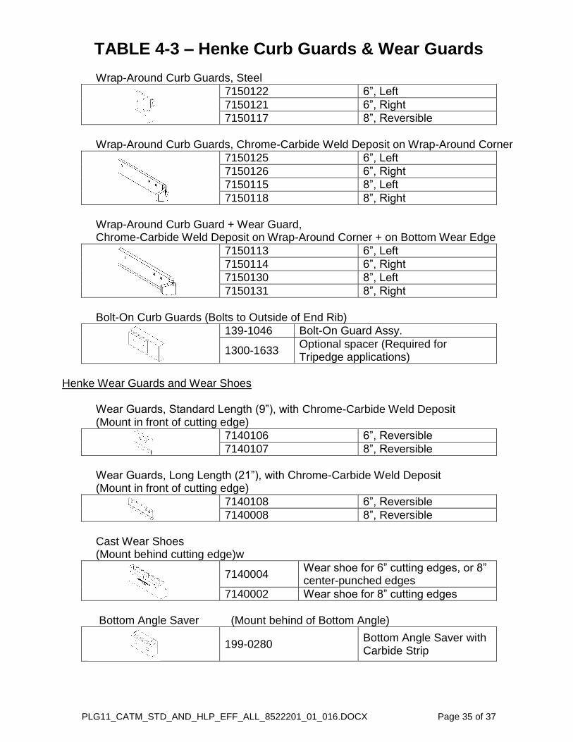
TABLE 4-3 – Henke Curb Guards & Wear Guards Wrap-Around Curb Guards, Steel
7150122 6”, Left
7150121 6”, Right
7150117 8”, Reversible
Wrap-Around Curb Guards, Chrome-Carbide Weld Deposit on Wrap-Around Corner
7150125 6”, Left
7150126 6”, Right
7150115 8”, Left
7150118 8”, Right
Wrap-Around Curb Guard + Wear Guard, Chrome-Carbide Weld Deposit on Wrap-Around Corner + on Bottom Wear Edge
7150113 6”, Left
7150114 6”, Right
7150130 8”, Left
7150131 8”, Right
Bolt-On Curb Guards (Bolts to Outside of End Rib)
139-1046 Bolt-On Guard Assy.
1300-1633 Optional spacer (Required for Tripedge applications)
Henke Wear Guards and Wear Shoes Wear Guards, Standard Length ( ”), with Chrome-Carbide Weld Deposit (Mount in front of cutting edge)
7140106 6”, Reversible
7140107 8”, Reversible
Wear Guards, Long Length (21”), with Chrome-Carbide Weld Deposit (Mount in front of cutting edge)
7140108 6”, Reversible
7140008 8”, Reversible
Cast Wear Shoes (Mount behind cutting edge)w
7140004
Wear shoe for 6” cutting edges, or 8” center-punched edges
7140002 Wear shoe for 8” cutting edges
Bottom Angle Saver (Mount behind of Bottom Angle)
199-0280
Bottom Angle Saver with Carbide Strip

HENKE LIMITED WARRANTY
1. LIMITED WARRANTIES1.01. Henke warrants for one year from the purchase date to the original non-commercial, governmental, or municipal purchaser
(“Purchaser”) and warrants for twelve months to the original commercial or industrial purchaser 1.02. Manufacturer will repair or replace for the Purchaser any part or parts found, upon examination at one of its factories, to be
defective under normal use and service due to defects in material or workmanship.1.03. This limited warranty does not apply to any part of the goods which has been subjected to improper or abnormal use, negligence,
alteration, modification, or accident, damaged due to lack of maintenance or use of wrong fuel, oil, or lubricants, or which hasserved its normal life. This warranty does not include normal wear items such as cutting edges, wear guards, scarifier teeth, etc.or improper installation. HMC warranty for any purchased components, such as hydraulic cylinders will be superceded by, andequal to the component manufacturer warranty.
1.04. Except as provided herein, no employee, agent, Dealer, or other person is authorized to give any warranties of any nature onbehalf of Manufacturer.
2. REMEDIES AND PROCEDURES.2.01. Warranty claims must be filled within 30 days of repair work during the one year warranty period and will be honored only if the
completed warranty registration form has been returned. Henke reserves the right to require proof of purchase of original Henkereplacement parts. If warranty is approved any allowed shipping expenses will be based on and will not exceed standard baseshipping charges.
2.02. Purchaser claims must be made in writing to the Authorized Dealer (“Dealer”) from whom Purchaser purchased the goods or anapproved Authorized Dealer (“Dealer”) within 30 days after Purchaser learns of the facts on which the claim is based.
2.03. Purchaser is responsible for returning the goods in question to the Dealer.2.04. If after examining the goods and/or parts in question, Manufacturer finds them to be defective under normal use and service due to
defects in material or workmanship, Manufacturer will:(a)Repair or replace the defective goods or part(s) or(b)Reimburse Purchaser for the cost of the part(s) and reasonable labor charges (as determined by Manufacturer) if Purchaser
paid for the repair and/or replacement prior to the final determination of applicability of the warranty by Manufacturer.The choice of remedy shall belong to Manufacturer.
2.05. Purchaser is responsible for any labor charges exceeding a reasonable amount as determined by Manufacturer and for returningthe goods to the Dealer, whether or not the claim is approved. Purchaser is responsible for the transportation cost for the goods orpart(s) from the Dealer to the designated factory.
3. LIMITATION OF LIABILITY.3.01. MANUFACTURER DISCLAIMS ANY EXPRESS (EXCEPT AS SET FORTH HEREIN) AND IMPLIED WARRANTIES WITH
RESPECT TO THE GOODS INCLUDING, BUT NOT LIMITED TO, MERCHANTABILITY AND FITNESS FOR APARTICULAR PURPOSE.
3.02. MANUFACTURER MAKES NO WARRANTY AS TO THE DESIGN, CAPABILITY, CAPACITY, OR SUITABILITY FOR USE OFTHE GOODS.
3.03. EXCEPT AS PROVIDED HEREIN, MANUFACTURER SHALL HAVE NO LIABILITY OR RESPONSIBILITY TO PURCHASER ORANY OTHER PERSON OR ENTITY WITH RESPECT TO ANY LIABILITY, LOSS, OR DAMAGE CAUSED OR ALLEGED TO BECAUSED DIRECTLY OR INDIRECTLY BY THE GOODS INCLUDING, BUT NOT LIMITED TO, ANY INDIRECT, SPECIAL,CONSEQUENTIAL, OR INCIDENTAL DAMAGES RESULTING FROM THE USE OR OPERATION OF THE GOODS OR ANYBREACH OF THIS WARRANTY. NOT WITHSTANDING THE ABOVE LIMITATIONS AND WARRANTIES, MANUFACTURER’SLIABILITY HEREUNDER FOR DAMAGES INCURRED BY PURCHASER OR OTHERS SHALL NOT EXCEED THE PRICE OFTHE GOODS.
3.04. NO ACTION ARISING OUT OF ANY CLAIMED BREACH OF THIS WARRANTY OR TRANSACTIONS UNDER THISWARRANTY MAY BE BROUGHT MORE THAN TWO (2) YEARS AFTER THE CAUSE OF ACTION HAS OCCURRED.
4. MISCELLANEOUS.4.01. Proper Venue for any lawsuits arising from or related to this limited warranty shall be only in Leavenworth County, Kansas.4.02. Manufacturer may waive compliance with any of the terms of this limited warranty, but no waiver of any terms shall be deemed to
be a waiver of any other term.4.03. If any provision of this limited warranty shall violate any applicable law and is held to be unenforceable, then the invalidity of such
provision shall not invalidate any other provisions herein.4.04. Applicable law may provide rights and benefits to purchaser in addition to those provided herein.
KEEP FOR YOUR RECORDS
ATTENTION: Purchaser should fill in the blanks below for his reference when buying repair parts and/or for proper machine identification whenapplying for warranty.
Henke Implement Model Serial Number
Date Purchased Dealer
ATTENTION:
READ YOUR OPERATOR'S MANUAL HENKE MANUFACTURINGAn Alamo Group Company
3070 WilsonLeavenworth, KS 66048
888-682-0300
PLG11_CATM_STD_AND_HLP_EFF_ALL_8522201_01_016.DOCX Page 37 of 37
DEALER WARRANTY PROCEDURE
For units delivered within the past 12 months, report any warranty
problems needing repair to our Product support department. Have
information ready regarding:
1. Henke unit model and serial number, 2. Model of equipment Henke unit is attached to (prime mover) 3. Description of the problem and any helpful information by the
end user. (Photos are always helpful).
Measurements or photos may be requested by Henke engineering for any issues regarding prime mover proximity and clearance, or any other unique considerations of fit and adaptability. These may be necessary for a proper repair recommendation and procedure.
Henke will respond with a written labor hour allowance for Henke participation on a faxed claim form and will ship any required replacement parts. If necessary, a repair procedure will be included on the claim form. A parts invoice will be generated to confirm shipment of the replacement parts.
If defective parts are needed for analysis, Henke will request their return.
Any such returned items are to be labeled with the claim number and returned to:
Henke Manufacturing Corp
ATTN: Product support
3070 Wilson Av
Leavenworth, Ks. 66048
RGA#_____________
The dealer should perform repairs as agreed on a dealer warranty repair order. Return the claim form with a copy of the dealer warranty repair order and service report. Credit as agreed will be issued to the dealer upon receipt of the dealer warranty repair order invoice (Pro-forma invoice), and upon receipt, inspection and warranty confirmation of the returned parts if any.
Parts & Service Assistance
Parts and service assistance is available between the hours of 8:00 AM and
5:00 PM, Central time, Monday through Friday. Call 913-682-9000.
Our web site, www.henkemfg.com, is a quick source for parts pricing and many
common parts diagrams
Parts purchase orders may be faxed in at any time to 913-682-0300. Faxed orders are encouraged, as they help insure order accuracy and follow up. Include any special instructions, such as drop ship addresses on your order.