Embed Size (px)
Citation preview

FOLDING_VEE_EFF_OCT09_TO_PRES_8500301_03_053.DOCX
HEAVY DUTY FOLDING VEE PLOW HENKE MODELS: FV12, FV14, FV16, FV20 For Motor Graders
PARTS BOOK AND INSTALLATION MANUAL SERIAL NUMBER __________________ VERSION 5.3, APRIL 2018
HENKE MANUFACTURING CORPORATION MANUFACTURERS OF SNOW REMOVAL EQUIPMENT OVER 100 YEARS 3070 WILSON AVE. LEAVENWORTH, KS 66048 PHONE (913)682-9000 FAX (913)682-0300 WEBSITE ADDRESS: WWW.HENKEMFG.COM EMAIL: [email protected]

Contact Your Local Dealer For Parts & Service Henke's Dealer Network is a key component in providing our customers with the quickest most effi-cient access to Henke's Parts and Technical Service teams. For Parts Replacement, Technical Service, & Customer Support Inquiries, please contact your local Henke dealer first. Find your dealer using our website Dealer Locator: http://henkemfg.com/dealer-locator/ If you do not have a local dealer, contact Henke directly, as listed below.
Replacement Parts Henke's Parts team will assist in parts replacement and preventative parts stocking program. Dealers and individual owners without a local dealer can contact us via email, website, or phone.
http://henkemfg.com/parts-and-service/
888 682-9010 x3 This will direct your inquiry to the entire Parts team, insuring the most prompt attention possible. All inquiries are processed in the order they are received.
NOTE: l We can prepare a personalized wear parts recommendation and optionally include your
seasonal purchasing summary. Just ask.
l Call Henke's Technical Service team in the unlikely event that your order is missing parts.

Technical Service & Customer Support Inquiries Henke Technical Service can assist in optimizing your Henke equipment, and increasing up-time by providing technical guidance and support for issues as they occur. Dealers and individual owners without a local dealer can contact us via email, website, or phone.
http://henkemfg.com/parts-and-service/
888 682-9010 x6 This will direct your inquiry to the entire Tech Service team, insuring the most prompt attention pos-sible. All inquiries are processed in the order they are received. We truly appreciate your business. Henke Parts and Technical Service Teams
Is This Your Product Manual?
l We strongly recommend verifying your product’s serial number and product manual num-ber and revision with Henke’s Parts Department before you order parts.
l Henke prides itself on service and support of all of our products including current, legacy, custom, and standard designs. Therefore, many of Henke products appear similar, but are different enough to justify having separate part manuals.
l Product manuals shown on product pages of the Henke website are only for standard, current production products.
l Product manuals may be updated at anytime.

FOLDING_VEE_EFF_OCT09_TO_PRES_8500301_03_053.DOCX Page 2 of 55
Introduction Thank you for your purchase of a Henke Heavy Duty Folding Vee Plow. The Folding Vee Plow features a multi-directional blade for loaders and graders. The Folding Vee is a down-pressure plow that operates as a “V” plow, reversing dozer blade, or scoop. It is a heavy duty, durable, and versatile unit which will provide years of reliable service. The parts list for the Folding Vee is listed in Table 2. This list is important and should be referred to when ordering replacement parts from your local dealer or Henke Manufacturing Corporation. The parts diagram for the Folding Vee is shown in Figure 1. This Product Manual should be read in its entirety before using your Henke Heavy Duty Folding Vee Plow. For customer service, replacement parts, or answers to questions about your Henke Plow, please call Henke Manufacturing at (913) 682-9000.

FOLDING_VEE_EFF_OCT09_TO_PRES_8500301_03_053.DOCX Page 3 of 55
Table of Contents Introduction .............................................................................................................. 2
Safety Section ....................................................................................... (Section 1) 6
Maintenance ............................................................................................................ 7
Preventing “Drift Out” – Discharging Trapped Accumulator Pressure ................... 10
Folding Vee Parts .................................................................................................. 11
Optional Float Assembly........................................................................................ 20
Optional Standard Style Rubber Shield Assembly ................................................ 24
Optional Flare Shield With Optional Rubber Shield Assemblies ............................ 27
Field Installation Instructions for Optional Flare Shields and Optional Rubber Shield for Flare Shields .................................................................................................... 35
Optional Large Tire Assembly ............................................................................... 37
Operations/Maintenance on Large Tire Running Gear .......................................... 44
Wear Parts ............................................................................................................ 48
Henke Warranty .................................................................................................... 53
Dealer Warranty Procedure ................................................................................... 55

FOLDING_VEE_EFF_OCT09_TO_PRES_8500301_03_053.DOCX Page 4 of 55
Figures FIGURE 1 – COVER .......................................................................................... COVER
FIGURE 2-1 – Henke Folding Vee ............................................................................. 11
FIGURE 2-2 – Folding Vee, Swivel Hitch Components, Current Style ....................... 13
FIGURE 2-3 – Swivel Hitch, Legacy Style .................................................................. 14
FIGURE 2-4 – Folding Vee, Center Pin Comparison ................................................. 15
FIGURE 2-5 – Mushroom Shoe Assembly ................................................................. 16
FIGURE 2-6 – Mushroom Fit, Retrofit Instructions ..................................................... 17
FIGURE 2-7 – Standard Folding Vee Hydraulic Kit 7080366 ..................................... 18
FIGURE 2-8 – Folding Vee Diverter Kit Option .......................................................... 19
FIGURE 3-1 – Optional Industrial Float Assembly ..................................................... 41
FIGURE 3-2 – Folding Vee A-Frame, Industrial Float Version, Parts List .................. 42
FIGURE 3-3 – Industrial Float Assembly, Plow-Side, Parts List ................................. 43
FIGURE 3-4 – Industrial Float Assembly, Machine-Side, Parts List ........................... 44
FIGURE 4-1 – Optional Rubber Shield Assembly, Without Flare Shield Assembly .... 24
FIGURE 4-2 – Optional Rubber Shield Assembly, Without Flare Shield, Parts View . 25
FIGURE 4-3 – Optional Rubber Shield Installation Schematic ................................... 26
FIGURE 5-1 – Optional Flare Shield With Optional Rubber Shield ............................ 27
FIGURE 5-2 – Flare Shield Installation and Adjustment ............................................. 28
FIGURE 5-3 – Top Shield Assembly, Flare Shield ..................................................... 29
FIGURE 5-4 – Center Side Plate Installation, Flare Shield......................................... 30
FIGURE 5-5 – Rubber Shield Installation, Flare Shield .............................................. 31
FIGURE 5-6 – Completed Flare Shield Installation, View 1 of 2 ................................. 32
FIGURE 5-7 – Completed Flare Shield Installation, View 2 of 2 ................................. 33
FIGURE 6-1 – Optional Large Tire Assembly ............................................................. 37
FIGURE 6-2 – Large Assembly Breakdown, Large Tire Assembly ............................ 38
FIGURE 6-3 – Large Tire Pivot Assembly .................................................................. 39
FIGURE 6-4 – Large Tire Skid Shoe Assembly .......................................................... 40
FIGURE 6-5 – Large Tire Wheel And Hub Assembly ................................................. 41
FIGURE 6-6 – Large Tire Fender and Mud Flap Assembly ........................................ 42
FIGURE 6-7 – Large Tire Skid Shoe Assembly .......................................................... 43
FIGURE 7-1 – Nose Guard Piece Comparison .......................................................... 51

FOLDING_VEE_EFF_OCT09_TO_PRES_8500301_03_053.DOCX Page 5 of 55
Tables TABLE 2-1 – Folding Vee, Parts List .......................................................................... 12
TABLE 2-2 – Folding Vee, Swivel Hitch, Current Style, Parts List .............................. 13
TABLE 2-3 – Swivel Hitch, Legacy Style, Parts List ................................................... 14
TABLE 2-4 – Mushroom Shoe Assembly, Parts List .................................................. 15
TABLE 2-5 – Mushroom Shoe Inboard Installation Distances .................................... 16
TABLE 2-6 – Standard Folding Vee Hydraulic Kit 7080366, Parts List ...................... 18
TABLE 2-7 – Folding Vee Diverter Kit Option, Parts List ............................................ 19
TABLE 3-1 – Folding Vee A-Frame, Industrial Float Version, Parts List .................... 21
TABLE 3-2 – Industrial Float Assembly, Plow-Side, Parts List ................................... 22
TABLE 3-3 – Industrial Float Assembly, Machine-Side, Parts List ............................. 23
TABLE 4-1 – Optional Rubber Shield Assembly, Without Flare Shield Assembly, Parts List .................................................................................................................... 25
TABLE 4-2 – Optional Rubber Shield Assemblies, Without Flare Shield Assembly ... 25
TABLE 6-1 – Large Tire Assembly, Large Assembly Breakdown, Parts List .............. 38
TABLE 6-2 – Large Tire Pivot Assembly, Parts List ................................................... 39
TABLE 6-3 – Large Tire Wheel And Hub Assembly, Parts List .................................. 41
TABLE 6-4 – Large Tire Fender and Mud Flap Assembly, Parts List ......................... 42
TABLE 6-5 – Large Tire Skid Shoe Assembly, Parts List ........................................... 43
TABLE 7-1 – Folding Vee Wear Kits, Parts List ......................................................... 49
TABLE 7-2 – Common Folding Vee Cutting Edges .................................................... 50
TABLE 7-3 – Nose Guard Piece Comparison, Parts List ........................................... 51
TABLE 7-4 – Cutting Edge Hardware ......................................................................... 52
TABLE 7-5 – Henke Curb Guard & Wear Guards ...................................................... 53

FOLDING_VEE_EFF_OCT09_TO_PRES_8500301_03_053.DOCX Page 6 of 55
<<THIS PAGE IS INTENTIONALLY LEFT BLANK>>

CHAPTER 1: SAFETYPLEASE READ ENTIRE BOOK BEFORE INSTALLATION,
OPERATION, OR MAINTENANCE.
Plow And Hitch SafetyDECALS - I PLOW

SAFETY
Plow Safety Section 1-2
© 2015 Alamo Group Inc.
SAFE
TY
GENERAL SAFETY INSTRUCTIONS AND PRACTICESA careful operator is the best operator. Safety is of primary importance to the manufacturer and should be tothe owner/operator. Most accidents can be avoided by being aware of your equipment, your surroundings,and observing certain precautions. The first section of this manual includes a list of Safety Messages that, iffollowed, will help protect the operat or and bystanders from injury or death. Read and u nderstand theseSafety Messages before assembling, operating or servicing this Implement. This equipment should only beoperated by those persons who have read the manual, who are responsible and trained, and who know howto do so responsibly.
The Safety Alert Symbol combined with a Signa l Word, as seen below, is used throughout thismanual and on decals which are attached to the equipment. The Safety Alert Symbol means:“ATTENTION! BECOME ALERT! YOUR SAFETY IS INVOLVED!” The Symbol and Signal Wordare intended to warn the owner/operator of impending hazards and the degree of possible injuryfaced when operating this equipment.
Indicates an imminently hazardous situation that, if not avoided, WILL result in DEATH ORVERY SERIOUS INJURY.
Indicates an imminently hazardous situation that, if not avoided, COULD result in DEATHOR SERIOUS INJURY.
Indicates an imminently hazardous situation that, if not avoided, MA Y result in MINORINJURY.
Identifies special instructions or procedures that, if not strictly observed, could result indamage to, or destruction of the machine, attachments or the environment.
NOTE: Identifies points of particular interest for more efficient and convenient operation or repair.
READ, UNDERSTAND, and FOLLOW the following Safety Messages. Serious injury ordeath may occur unless care is taken to follow the warnings and instructions stated in thisManual and in the Safety Messages on the implement. Always follow the instruction in thismanual and use good common sense to avoid hazards.
Pictographs are used throughout this manual to help bring your visual attention to safety issues.
NOTE: If you want a translation of this safety section in one of the following Languages, please contact:Translations at 1502 E. Walnut Street Seguin, TX 78155; Fax: (830) 372-9529; Safety Section Translationsare available in Spanish, Portuguese, French, German, Russian. P-GS-01
Practice all usual and customary safe working precautions and above all---remember safety is up to YOU. Only YOU can prevent serious injury or deathfrom unsafe practices.

SAFETY
Plow Safety Section 1-3
SAFETY
© 2015 Alamo Group Inc.
OPERATOR SAFETY
TO AVOID SERIOUS INJURY OR DEATH DO THE FOLLOWING:
• READ, UNDERSTAND and FOLLOW Operator's Manual instructions, Warnings and Safety Messages.• WEAR SAFETY GLASSES, safety shoes, hard hat and gloves when operating or repairing equipment• DO NOT WEAR loose clothing or jewelry to avoid rotating parts entanglement injury.• DO NOT USE DRUGS or ALCOHOL before or while operating equipment. • DO NOT ALLOW anyone to operate equipment under the influence of drug or alcohol.• CONSULT medical professional for medication impairment side effects.• STAY ALERT, prolonged operation can cause fatigue; STOP and REST.GENERAL OPERATING SAFETYVISIBILITY CONDITIONS WHEN PLOWING:• OPERATE IN DAYLIGHT or with lights that give at least 100 yards clear visibility.• BE ABLE TO SEE and identify passersby, steep slopes, ditches, drop-offs, overhead obstructions, power lines, debris and
foreign objects.GROUND SPEED WHEN PLOWING:• NORMAL SPEED range is between 5 to 45mph.• ADJUST plowing SPEED for terrain conditions.• REDUCE plowing SPEED when near steep slopes, ditches, drop-offs, overhead obstructions, and power lines.SAFETY SIGNS AND WARNING DECALS:• REPLACE missing, damaged or unreadable safety signs immediately. SHIELDING:• NEVER remove protective shields and guards! NEVER modify or cut protective shields or guards!PROLONGED OPERATION IN COLD WEATHER:• May Cause Operator Hypothermia affecting safe operation of implement.• Wear appropriate clothing and take scheduled breaks. • If possible shut down equipment, exit cab, and warm body in properly heated area. • NEVER operate implement in fatigued or impaired mental state.COMMUNICATION:• Verbal Communication can be difficult and dangerous near implement.• Operating instructions and directions should be made prior to starting implement.• If communication is necessary completely shutdown and exit implement.• NEVER allow anyone to approach implement while in operation. RIDING PASSENGERS:• Never allow passengers whose presence distracts from safe operation or transporting of implement• If passengers presence is needed, passenger must be seated securely and belted in passenger seat. • DO NOT allow passenger in any other area of implement, other than in passenger seat during operation or transport. CHEMICAL HAZARD• Wear appropriate PPE when handling chemicals. Refer to Chemical MSDS sheets.• Always wear safety glasses, shield, gloves, and apron.• Wear Respirator when required. PN P-OS-01

SAFETY
Plow Safety Section 1-4
© 2015 Alamo Group Inc.
SAFE
TY
PERSONAL PROTECTION EQUIPMENT - PPE
SALT AND MATERIAL SPREADING
Always wear all protective clothing and personal safety devices issued to you or called for by jobconditions. This should always include:• Hard hat - when working around raised hopper.• Steel toed Safety shoes.• Safety glasses, goggles or face shield.• Close fitted clothing.• Heavy gloves (chemical resistant).• Reflective clothing.PN PPE-02
When spreading salt or other materials make sure to wear appropriate protective clothing and personal safetydevices such as respirator, heavy gloves that are chemical resistant, face shield, or goggles. PN PPE-03

SAFETY
Plow Safety Section 1-5
SAFETY
© 2015 Alamo Group Inc.
CRUSHING HAZARDS
TO AVOID SERIOUS INJURY OR DEATH FROM FALLING OFF VEHICLE, EQUIPMENTRUN OVER, ROLLOVER AND CRUSHING BY FALLING IMPLEMENT:
CRUSHING BY FALLING from EQUIPMENT• ALWAYS BUCKLE UP seat belt when operating vehicle and equipment.• ONLY OPERATE vehicle and equipment while seated in vehicle seat.• STOP VEHICLE ENGINE, place transmission into park, engage parking brake, and remove key. TO AVOID FALLING OFF OR BEING CRUSHED BY EQUIPMENT• Use extreme care when climbing onto vehicle or attachment. Also always use three point contact using
available handles and steps on vehicle or power unit while exiting. • Removing the vehicle key is a lockout procedure to prevent a coworker from starting the vehicle while
someone is working on attachment.• Never Attempt to mount the vehicle or attachment while unit is moving.• Do not remove safety latches or chains on stowed equipment unless stowed equipment is being held in
place by active hydraulic power or other secure method to prevent if from dropping. TO AVOID CHILDREN FALLING OFF OR BEING CRUSHED BY EQUIPMENT:• NEVER ALLOW children to play on or around vehicle or equipment. PN P-CH-01

SAFETY
Plow Safety Section 1-6
© 2015 Alamo Group Inc.
SAFE
TY
CONNECTING OR DISCONNECTING IMPLEMENT SAFETY
TO AVOID SERIOUS INJURY OR DEATH FROM BEING CRUSHED BY VEHICLE ORATTACHEMENT:
WHEN ATTACHING UNIT TO VEHICLE: • DO NOT ALLOW BYSTANDERS between vehicle and plow.• Keep hands and body clear of the attachment and the attachment mounts.BEFORE connecting and disconnecting Plow Components: • STOP VEHICLE ENGINE, place transmission into park, engage parking brake, and remove key.WHEN connecting and disconnecting Plow:• DO NOT crawl or walk under the Plow when in storage position.• Make sure Plow is properly attached to vehicle and the retaining pins, hardware, chains, and cables
securely lock the Attachment into position.• DO NOT attempt to disconnect trip edge by hand. Trip devices are spring loaded and sudden movement
can occur resulting in serious injuries. PN P-CD-01

SAFETY
Plow Safety Section 1-7
SAFETY
© 2015 Alamo Group Inc.
RUN OVER HAZARDS
TO AVOID SERIOUS INJURY OR DEA TH FROM FALLING OFF VEHICLE OREQUIPMENT RUN OVER:
• ONLY start vehicle while seated in vehicle seat.• ALWAYS BUCKLE UP seat belt when operating vehicle and equipment. • ONLY OPERATE vehicle and equipment while seated in vehicle seat. • NEVER ALLOW RIDERS on vehicle or implement.• Ensure area is clear around vehicle and equipment before starting or operating equipment. WHEN MOUNTING AND DISMOUNTING VEHICLE: • ONLY mount or dismount when vehicle and moving parts are stopped.• STOP ENGINE, engage parking brake, lower implement, allow all moving parts to stop and
remove key before dismounting from vehicle. PN P-RO-01

SAFETY
Plow Safety Section 1-8
© 2015 Alamo Group Inc.
SAFE
TY
THROWN OBJECTS HAZARDS
PLOW IS CAPABLE OF PROPELLING OBJECTS UP TO 75 FEET.
TO AVOID SERIOUS INJURY TO OPERATOR OR PASSERSBY FROM THROWN OBJECTS:• KEEP bystanders 100 feet away• Stop plowing if bystanders are within the potential thrown area.STOP PLOWING IF PASSERSBY ARE WITHIN 100 FEET:• Make sure no bystander, animal or obstruction such as vehicle, building or street sign are within the width
of plow.• Avoid hitting solid, or oversized objects. Objects could become airborne and cause personal injury or
damage to equipment. • Remove or mark any foreign objects that could be propelled or cause damage to plow. PLOW OPERATION:• DO NOT exceed Plow’s rated plowing speed.• Ensure plow is equipped with warning signals to alert motorist and pedestrians. • Always turn on all safety lights and flashers when operating plow. PN P-TO-01

SAFETY
Plow Safety Section 1-9
SAFETY
© 2015 Alamo Group Inc.
BLADE CONTACT HAZARDS
HIGH PRESSURE OIL LEAK HAZARD
KEEP AWAY FROM BLADE TO AVOID SERIOUS INJURY OR DEATH FROM BLADE CONTACT:
• STAY AWAY and KEEP HANDS, FEET and BODY AWAY from plow blade and parts until engine has come to a complete stop.
• DO NOT put hands or feet under plow blade.• STOP, disengage power and ensure plow is resting and supported on blocks before adjusting plow blade.• STOP, LOOK, and LISTEN before approaching the plow to make sure engine has stopped. PN P-BC-01
TO AVOID SERIOUS INJURY OR DEATH FROM HIGH PRESSURE HYDRAULIC OIL LEAKSPENERATING SKIN:
• DO NOT OPERATE equipment with oil or fuel leaks.• KEEP all hydraulic hoses, lines and connections in GOOD CONDITION and TIGHT before applying system
pressure. • RELIEVE HYDRAULIC PRESSURE before disconnecting lines or working on the system. • REMOVE and replace hose if you suspect it leaks. Have dealer test it for leaks.HIGH PRESSURE FLUID LEAKS CAN BE INVISIBLE.WHEN CHECKING FOR HYDRAULIC LEAKS AND WORKING AROUND HYDRAULIC SYSTEMS:• ALWAYS WEAR safety glasses and impenetrable gloves. • USE paper or cardboard to search for leaks.• DO NOT USE hands or body parts to search for leak.• KEEP hands and body AWAY from pin holes and nozzles ejecting hydraulic fluid.• Injected Hydraulic fluid may cause gangrene if not surgically removed immediately by a doctor familiar with this form
of injury. PN HP01

SAFETY
Plow Safety Section 1-10
© 2015 Alamo Group Inc.
SAFE
TY
TRANSPORTING HAZARDS
TO AVOID SERIOUS INJURY AND DEATH WHEN OPERATING OR TRANSPORTINGEQUIPMENT:
• KEEP transport speed to the posted speed limit to maintain control of equipment.• REDUCE SPEED on inclines, on turns and in poor plowing conditions.• DO NOT TOW with trucks or other vehicles use a flatbed vehicle to transport.• FOLLOW all local traffic regulations.BEFORE TRANSPORTING OR TOWING IMPLEMENT:• Ensure equipment has been stowed in transport position and secured with safety latches or chains.VEHICLE INSPECTION:• CHECK steering and braking for proper operation and in good condition. • CHECK that transport pins are engaged.• CHECK reflectors and warning lights for proper operation and visibility behind unit.• ROUTINELY inspect the equipment’s headlights, brake lights, backup lights, and turn signal lights for
operational condition.• Always turn on all safety lights and flashers when you operate the implement. • CHECK that your driving vision is not impaired by cab while seated in vehicle seat.• ADJUST your operating position, mirrors, and implement transport for clear vision for traveling and traffic
conditions.DETERMINE STOPPING CHARACTERISTICS OF VEHICLE AND IMPLEMENT FOR TRANSPORTINGOR OPERATING:• With added weight and severe weather conditions stopping distances may increase.• Only operate at speeds that you can properly control equipment.DETERMINE MAXIMUM TURNING SPEED BEFORE OPERATING ON ROADS OR UNEVEN GROUND:• TEST equipment in slowly increasing speed on turns to determine it can be operated at higher speeds.• USE REDUCED turning speeds on sharp turns to avoid equipment turning over.• Center of gravity may have shifted with equipment installation.WHEN OPERATING OR TRANSPORTING EQUIPMENT:• Always WEAR SEAT BELT when operating or transporting spreader.• USE low speeds to avoid overturn while operating or transporting.• USE low speeds and gradual steering on curves, hills, rough or uneven surfaces and on wet roads. • Use extreme caution when operating the equipment in traffic.• Use all equipped warning signals to alert motorist and pedestrians of the presence of the equipment• DO NOT leave piled material on roadway. Material can be a hazard to other motorist. TO AVOID SERIOUS INJURY OR DEATH FROM ELECTRICAL CON TACT WHEN WORKING AROUNDELECTRICAL POWER LINES AND UTILITY LINES:• INSPECT area for overhead power lines, obstructions, cables and utility lines, municipal, or other type
structure.• KEEP Plow 10 feet or greater distance from all power lines and overhead obstructions.• DO NOT allow Plow to contact with any utility, municipal, or type of structures and obstructions. P-TH-01
SAFETY
Plow Safety Section 1-11
SAFETY
© 2015 Alamo Group Inc.
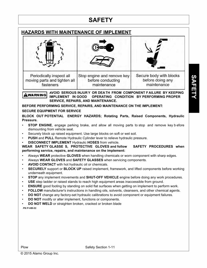
HAZARDS WITH MAINTENANCE OF IMPLEMENT
AVOID SERIOUS INJUR Y OR DEATH FROM COMPONENT FAILURE BY KEEPINGIMPLEMENT IN GOOD OPERATING CONDITION BY PERFORMING PROPERSERVICE, REPAIRS, AND MAINTENANCE.
BEFORE PERFORMING SERVICE, REPAIRS, AND MAINTENANCE ON THE IMPLEMENT:SECURE EQUIPMENT FOR SERVICEBLOCK OUT POTENTIAL ENERGY HAZARDS; Rotating Parts, Raised Components, HydraulicPressure.• STOP ENGINE, engage parking brake, and allow all moving parts to stop and remove key b efore
dismounting from vehicle seat. • Securely block up raised equipment. Use large blocks on soft or wet soil.• PUSH and PULL Remote Hydraulic Cylinder lever to relieve hydraulic pressure.• DISCONNECT IMPLEMENT Hydraulic HOSES from vehicle.WEAR SAFETY GLASSE S, PROTECTIVE GLOVES and follow SAFETY PROCEDURES whenperforming service, repairs, and maintenance on the implement:• Always WEAR protective GLOVES when handling chemicals or worn component with sharp edges.• Always WEAR GLOVES and SAFETY GLASSES when servicing components.• AVOID CONTACT with hot hydraulic oil or chemicals.• SECURELY support or BLOCK UP raised implement, framework, and lifted components before working
underneath equipment.• STOP any implement movements and SHUT-OFF VEHICLE engine before doing any work procedures.• USE step ladder or raised stands to reach high equipment areas inaccessible from ground.• ENSURE good footing by standing on solid flat surfaces when getting on implement to perform work.• FOLLOW manufacturer's instructions in handling oils, solvents, cleansers, and other chemical agents.• DO NOT change any factory-set hydraulic calibrations to avoid component or equipment failures.• DO NOT modify or alter implement, functions or components.• DO NOT WELD or straighten broken, cracked or broken blade PN P-HM-01

SAFETY
Plow Safety Section 1-12
© 2015 Alamo Group Inc.
SAFE
TY
HAZARDS WITH MAINTENANCE OF IMPLEMENT CONTINUED
AVOID SERIOUS INJUR Y OR DE ATH FROM COMPONENT FAILURE BY KEEPINGIMPLEMENT IN GOOD OPERA TING CONDITION BY PERFORMING PROPERSERVICE, REPAIRS AND MAINTENANCE.
PERFORM SERVICE, REPAIRS, LUBRICATION AND MAINTENANCE OUTLINED IN IMPLEMENTMAINTENANCE SECTION:• INSPECT before each use for loose fasteners, worn or broken parts, leaky or loose fittings, missing or
broken cotter keys and washers on pins, and all moving parts for wear.• REPLACE Blade or any worn or broken parts with authorized service parts.• LUBRICATE unit as specified by lubrication schedule.• Ensure all fluid levels are properly filled.• NEVER lubricate, adjust or remove material while it is running or in motion.• TORQUE all bolts and nuts as specified.• Check tire conditions.• Never remove debris or unclog jams from spring pressurized pinch points by hand.• Avoid contact with recently used equipment that may still be hot. • Ensure the scheduled maintenance is up to date. • Do Not modify or alter equipment/plow.• Do Not leave snow plow unattended while snow plow wing is in an unsecured raised position. • Do Not crawl or walk under unsecured raised equipment. SAFETY SHIELDS, GUARDS AND SAFETY DEVICES INSPECTION:• KEEP all Steel Guards, Bands, and Skid Shoes in place and in good condition.• Maintain Safety Signs and Decals in good readable condition.• REPLACE any missing, broken or worn safety shields, guards and safety devices.• Engine Exhaust, some of its constituents, and certain vehicle components contain or emit chemicals
known to the state of California to cause cancer, birth defects or other reproductive harm.• Battery posts, terminals and related accessories contain lead and lead compounds, chemicals known to
the state of California to cause cancer, birth defects or other reproductive harm. PN P-HM-02

SAFETY
Plow Safety Section 1-13
SAFETY
© 2015 Alamo Group Inc.
PARTS INFORMATION
HENKE Snow Plows use balanced and matched system components for plows, hitches, and othercomponents. These parts are made and tested to HENKE specifications. Non-genuine or “will fit" parts donot consistently meet these specifications. The use of non-genu ine or “will fit” parts may reduce Snow Plowperformance, void HENKE warranties, and present a safety hazard. Use genuine HENKE parts for economyand safety. (SNPG-6)
SEE YOUR HENKE DEALER

FOLDING_VEE_EFF_OCT09_TO_PRES_8500301_03_053.DOCX Page 7 of 55
IN SEASON MAINTENANCE Snow removal equipment must be cared for and maintained regularly. Daily or pre-route inspection and maintenance are necessary. Failure to do so may affect efficiency and safety.
A visual inspection must be carried out after every 8 hours of operation. Look for damaged components, bends, cracked welds or hydraulic leaks. REPAIR IMMEDIATELY! It is recommended to re-torque all bolts after the first 8 hours of use and to regularly check for loosened or missing fasteners. Replace any damaged or missing fasteners immediately.
Because of the environment in which snow equipment is expected to operate, hydraulic lines, fasteners, wearable or replaceable items and warning decals may become damaged by snow, ice and road debris. These items must be inspected daily and replaced if necessary to avoid equipment damage or personal injury.
Lubrication of moving parts is of the utmost importance. Exposure to snow, ice, salt and road debris will wash away lubrication quickly and it may be necessary to inspect and reapply lubrication more than once a day.
FOLDING_VEE_EFF_OCT09_TO_PRES_8500301_03_053.DOCX Page 8 of 55
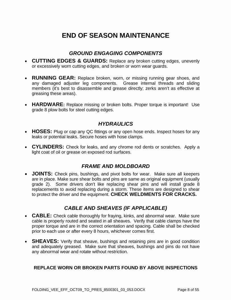
END OF SEASON MAINTENANCE
GROUND ENGAGING COMPONENTS
CUTTING EDGES & GUARDS: Replace any broken cutting edges, unevenly or excessively worn cutting edges, and broken or worn wear guards.
RUNNING GEAR: Replace broken, worn, or missing running gear shoes, and any damaged adjuster leg components. Grease internal threads and sliding members (it’s best to disassemble and grease directly; zerks aren’t as effective at greasing these areas).
HARDWARE: Replace missing or broken bolts. Proper torque is important! Use grade 8 plow bolts for steel cutting edges.
HYDRAULICS
HOSES: Plug or cap any QC fittings or any open hose ends. Inspect hoses for any leaks or potential leaks. Secure hoses with hose clamps.
CYLINDERS: Check for leaks, and any chrome rod dents or scratches. Apply a light coat of oil or grease on exposed rod surfaces.
FRAME AND MOLDBOARD
JOINTS: Check pins, bushings, and pivot bolts for wear. Make sure all keepers are in place. Make sure shear bolts and pins are same as original equipment (usually grade 2). Some drivers don’t like replacing shear pins and will install grade 8 replacements to avoid replacing during a storm. These items are designed to shear to protect the driver and the equipment. CHECK WELDMENTS FOR CRACKS.
CABLE AND SHEAVES (IF APPLICABLE)
CABLE: Check cable thoroughly for fraying, kinks, and abnormal wear. Make sure cable is properly routed and seated in all sheaves. Verify that cable clamps have the proper torque and are in the correct orientation and spacing. Cable shall be checked prior to each use or after every 8 hours, whichever comes first.
SHEAVES: Verify that sheave, bushings and retaining pins are in good condition and adequately greased. Make sure that sheaves, bushings and pins do not have any abnormal wear and rotate without restriction.
REPLACE WORN OR BROKEN PARTS FOUND BY ABOVE INSPECTIONS

FOLDING_VEE_EFF_OCT09_TO_PRES_8500301_03_053.DOCX Page 9 of 55
<<THIS PAGE IS INTENTIONALLY LEFT BLANK>>

FOLDING_VEE_EFF_OCT09_TO_PRES_8500301_03_053.DOCX Page 10 of 55
Preventing “Drift Out” – Discharging Trapped Accumulator Pressure
THE COMMON PROBLEM:
When shutting a machine down, operators will often move the FV plow into the Vee position, bumping against the mechanical stops.
This causes system pressure to spike, compressing the nitrogen accumulator the corresponding relief setting.
When the operator then releases the control handle, relief pressure is then often trapped in the accumulator.
With time this pressure causes drifting out, pushing the plow toward the scoop position.
THE EASY SOLUTION:
Before shutting down a machine with a Henke FV Plow, use the FV plow controls to slightly push the plow out toward the scoop position while the plow is raised.
THE SIMPLE EXPLANATION:
Taking this step discharges any pressure trapped in the accumulators.
Otherwise, pressurized oil can seep into the cylinder lines, and pressurize the cylinders.
If this happens the cylinders could slowly extend, moving the FV Moldboards into the scoop position.

FO
LDIN
G_V
EE
_EF
F_O
CT
09_TO
_PR
ES
_8500301_03_053.DO
CX
P
age 11 of 55
FIGURE 2-1 – Henke Folding Vee

FOLDING_VEE_EFF_OCT09_TO_PRES_8500301_03_053.DOCX Page 12 of 55
Item No. Qty. Part No. Description
1 1239‐0464
239‐0457
Hitch Assembly, Non‐Swivel (Shown)
Hitch Assembly ‐ Swivel ‐ (See Separate Exploded View)
2 1 Call Henke Moldboard Assembly, Right
3 1 Call Henke Moldboard Assembly, Left
4 0‐1 2700‐0235 Wrench (Supplied with optional Mushroom Shoe Assembly only)
5 4 7020370 Hex Capscrew, 5/16‐18 x 1 Gr. 8
6 8 7030086 Nylock Nut, 5/16‐18 Gr. 2
7 2 7080341 Hydraulic Accumulator, with Bracket
7a 2 7080342 Accumulator Bracket (also included with 7080341)
8 1 7020087 Hex Capscrew, 3/4‐10 x 6 Gr.5
9 1 Varies Center Pin (See Separate Figure: Center Pin Comparison)
10 1 7030030 Toplock Nut, 3/4‐10 Gr. C
11 1 7020372 Hex Capscrew, 5/16‐18 X3 GR. 2
12 2 7080322 Cushion Relief Valve, 2000 psi
13 1 7090111 Grease Fitting, 1/4‐28
14 2 289‐0176 Pin Assembly, 1.38 x 5.0 x 4.63 Grip
15 2 289‐0175 Pin Assembly, 1.38 x 4.0 x 3.63 Grip
16 2 7080832 Hydraulic Cylinder, 4 x 20.75 x 2
16a N/A 7080932 Seal Kit for Cylinder 7080832 (not shown)
17 4 7050099 Cotter Pin 1/4 x2.5
18 1 Call Henke
Nose Guard, Folding Vee
(This is a replaceable wear Part. Design has change over time.)
(See Separate Parts Comparison View)
19 4 Call HenkeFlat Head Socket Capscrew, 5/8‐11
(See Separate Nose Guard Table and Associated Notes.)
20 Varies 7030084 Toplock Nut, 5/8‐11 GR. C
21Varies
VariesCall Henke
Cutting Edge, Right, Folding Vee
Cutting Edge, Left, Folding Vee
(IMPORTANT: See Cutting Edge Table and Associated Notes.)
22Varies
Varies
7150003
7150002
Plow Bolt, 5/8‐11 x 2.5 Gr. 8
Plow bolt, 5/8‐11 x 3 GR. 8
(3" length required for cutting edges thicker than 3/4")
23 0 or 2 ReferenceOptional Mushroom Shoe Assembly
(See Separate Exploded View)
24 8 7020344 Flat Head Socket Cap Screw, 5/8‐11 x 4 GR. 8
25 2 289‐0193 Skid Skid Shoe
26 20 2800‐0416 Skid Shoe Shim
TABLE 2-1 – Henke Folding Vee, Parts List
FOLDING_VEE_EFF_OCT09_TO_PRES_8500301_03_053.DOCX Page 13 of 55
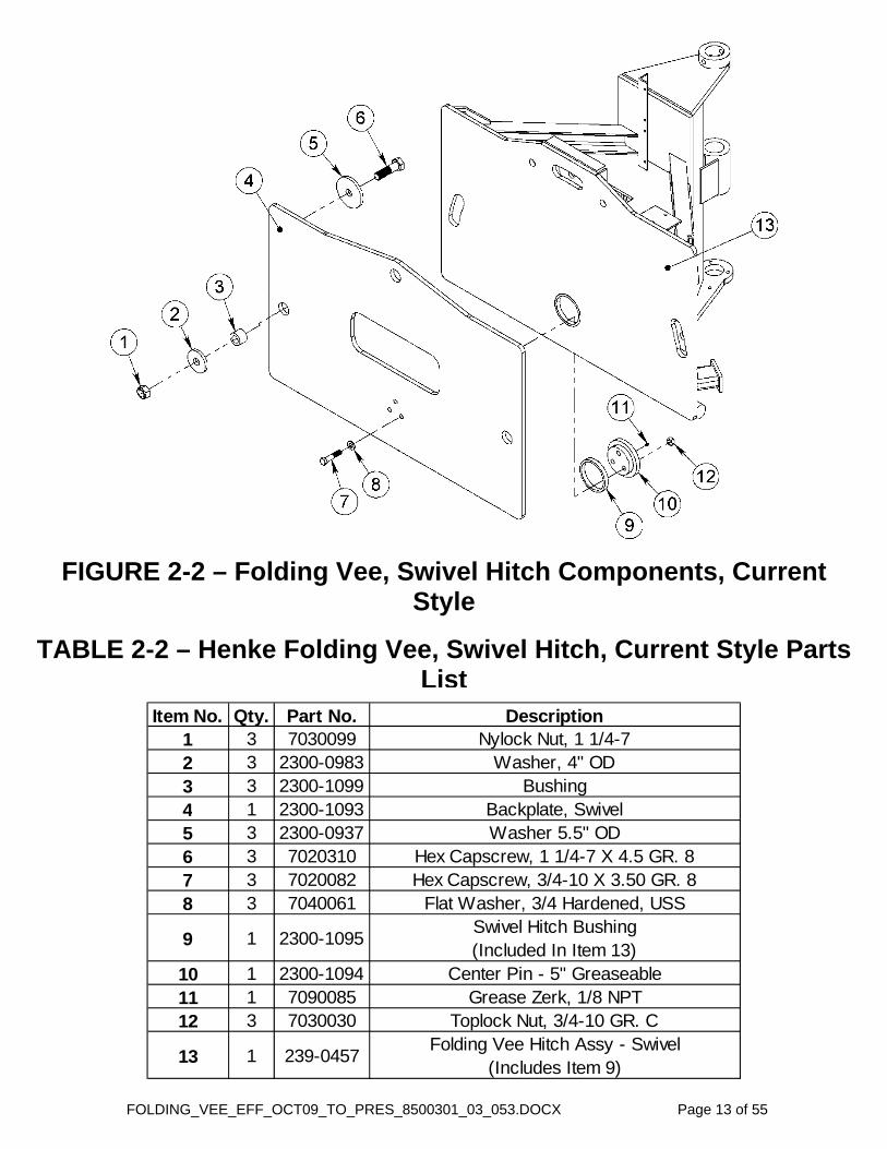
TABLE 2-2 – Henke Folding Vee, Swivel Hitch, Current Style Parts List
Item No. Qty. Part No. Description1 3 7030099 Nylock Nut, 1 1/4-72 3 2300-0983 Washer, 4" OD3 3 2300-1099 Bushing4 1 2300-1093 Backplate, Swivel5 3 2300-0937 Washer 5.5" OD6 3 7020310 Hex Capscrew, 1 1/4-7 X 4.5 GR. 87 3 7020082 Hex Capscrew, 3/4-10 X 3.50 GR. 88 3 7040061 Flat Washer, 3/4 Hardened, USS
9 1 2300-1095Swivel Hitch Bushing(Included In Item 13)
10 1 2300-1094 Center Pin - 5" Greaseable11 1 7090085 Grease Zerk, 1/8 NPT12 3 7030030 Toplock Nut, 3/4-10 GR. C
13 1 239-0457Folding Vee Hitch Assy - Swivel
(Includes Item 9)
FIGURE 2-2 – Folding Vee, Swivel Hitch Components, Current Style

FOLDING_VEE_EFF_OCT09_TO_PRES_8500301_03_053.DOCX Page 14 of 55
Item No. Qty Part No. Description
1 1 7020231 Hex Capscrew, 1 1/2-12 x 5.5 Gr. 5
2 2 7090111 Grease Fitting, Straight, 1/4-28
3 2 2300-0308 Plate
4 2 2300-0106 Fixed Shim
5 1 2300-0309 Tube
6 1 7030088 Nut, 1 1/2-12 Toplock Gr. C
FIGURE 2-3 – Swivel Hitch, Legacy Style
TABLE 2-3 – Swivel Hitch, Legacy Style, Parts List

FOLDING_VEE_EFF_OCT09_TO_PRES_8500301_03_053.DOCX Page 15 of 55
FIGURE 2-4 – Folding Vee, Center Pin Comparison

FOLDING_VEE_EFF_OCT09_TO_PRES_8500301_03_053.DOCX Page 16 of 55
TABLE 2-4 – Mushroom Shoe Assembly,
Parts List Item No. Qty Part No. Description
1 1 199-0358 Outer Tube Assembly2 1 199-0044 Inner Tube Assembly3 1 7140001 Mushroom Shoe4 1 199-0041 Acme Screw Assembly5 1 1900-0296 Caster Screw Lock6 1 7050028 Roll Pin, 3/8 x 27 1 7050090 Safety Pin8 2 7020288 Hex Capscrew, 5/8-11 x 2.5 Gr. 89 2 7030084 Nut, 5/8-11 Toplock Gr. C
FIGURE 2-5 – Mushroom Shoe Assembly
Full Assembly including wrench, 2700-0235, and weld-on wrench holder, 2700-0234, may be purchased together as Henke Part #: 6084114.

FOLDING_VEE_EFF_OCT09_TO_PRES_8500301_03_053.DOCX Page 17 of 55
Model Distance From Outer RibFV12 13.50"FV14 19.25"FV16 31.25"FV20 13.50"
TABLE 2-5 – Mushroom Shoe Inboard Installation Distances
FIGURE 2-6 – Mushroom Shoe, Retrofit Instructions

FOLDING_VEE_EFF_OCT09_TO_PRES_8500301_03_053.DOCX Page 18 of 55
Item No. Part No. Qty. Description1 7110483 2 Hose Assembly, 1/2 2-wire x 20” total, -10 JIC F e/e2 7110484 2 Hose Assembly, 1/2 2-wire x 31.5” total, -8 JIC F x -10 JIC F3 7110485 2 Hose Assembly, 1/2 2-wire x 22.5” total, -8 JIC F e/e4 7090014 6 Straight Adapter, -8 JIC M x -10 ORB M5 7090235 6 Elbow, 90, -8 JIC M x -8 JIC F6 7090009 4 Cap, -8 JIC (Not Shown)7 7090257 4 Elbow, 90, -8 JIC M x -8 ORB Adj. M8 7090480 2 Tee, -10 JIC M, -10 ORB Adj. M Branch9 7090132 2 Elbow, 90, -10 JIC M x -12 ORB Adj. M
FIGURE 2-7 – Standard Folding Vee Hydraulic Kit
7080366
2
PLOW HITCH
PLOW HITCH
PLOW HITCH
PLOW HITCH
4
8
1
2
9
3
5
7
4
5
5
7 2 3
7 3
7
TABLE 2-6 – Standard Folding Vee Hydraulic Kit 7080366
NOTE: Drifting out of Folding Vee Wings can be alleviated by “bumping” the angle cylinder controls in and out (with no load on cylinders; plow slightly raised, and off the stops); this will discharge accumulator pressure allowing Folding Vee wings to remain stationary when at rest.
FOLDING_VEE_EFF_OCT09_TO_PRES_8500301_03_053.DOCX Page 19 of 55
(1) 7110719 (1) 7090014 (1) 7110718
(1) 7090014
(1) 7110716(1) 7110717
(1) 7080620, (1) 7080621, (1) 7080425 (1) 7020360, (2) 7020360, (2) 7030086
(4) 7090014 (4) 7090235 (2) 7090009
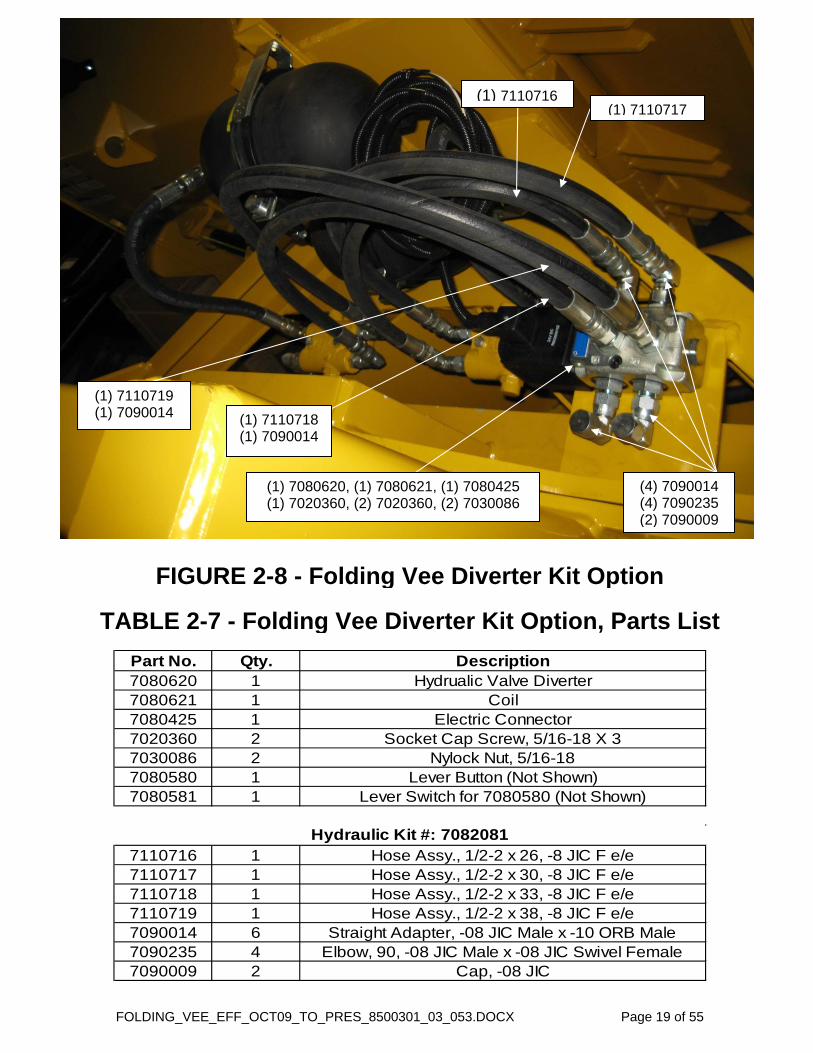
Part No. Qty. Description7080620 1 Hydrualic Valve Diverter7080621 1 Coil7080425 1 Electric Connector7020360 2 Socket Cap Screw, 5/16-18 X 37030086 2 Nylock Nut, 5/16-187080580 1 Lever Button (Not Shown)7080581 1 Lever Switch for 7080580 (Not Shown)
7110716 1 Hose Assy., 1/2-2 x 26, -8 JIC F e/e7110717 1 Hose Assy., 1/2-2 x 30, -8 JIC F e/e7110718 1 Hose Assy., 1/2-2 x 33, -8 JIC F e/e7110719 1 Hose Assy., 1/2-2 x 38, -8 JIC F e/e7090014 6 Straight Adapter, -08 JIC Male x -10 ORB Male7090235 4 Elbow, 90, -08 JIC Male x -08 JIC Swivel Female7090009 2 Cap, -08 JIC
Hydraulic Kit #: 7082081
FIGURE 2-8 - Folding Vee Diverter Kit Option
TABLE 2-7 - Folding Vee Diverter Kit Option, Parts List

FOLDING_VEE_EFF_OCT09_TO_PRES_8500301_03_053.DOCX Page 20 of 55
FIGURE 3-1 – Optional Industrial Float Assembly

FOLDING_VEE_EFF_OCT09_TO_PRES_8500301_03_053.DOCX Page 21 of 55
TABLE 3-1 – Folding Vee A-Frame, Industrial Float Version, Parts List
Item No. Qty. Part No. Description
1 1 239-0664 A-Frame Assembly, Float Hitch, FV
2 1 239-0467 Nose Guard Weldment, Current Design3 4 7020274 Flathead Set Screw, 5/8-11 x 1.75 GR.8
FIGURE 3-2 – Folding Vee A-Frame, Industrial Float Version

FOLDING_VEE_EFF_OCT09_TO_PRES_8500301_03_053.DOCX Page 22 of 55
TABLE 3-2 – Industrial Float Assembly, Plow-Side, Parts List This assembly may be purchased as Henke Assembly No. 6145121.
6145121 Includes Folding Vee Float Hitch and Nose Guard (Current Design Only).
Item No. Qty. Part No. Description
1 1 Reference Hitch Plate - Float2 4 7030031 Toplock Nut, 1/2-13 GR.C3 8 7040005 Flat Washer, 1/2 Hardened, USS4 4 279-0381 Pin Assembly-STD LG5 4 7020144 Hex Capscrew, 1/2-13 x 2.25 GR.86 4 2300-1407 Float Plate Links7 2 7040051 Flat Washer, 1-1/4 SAE8 1 239-0680 Outer Tube Assembly - Float Spring9 2 7050099 Cotter Pin, 1/4 x 2.510 2 139-1657 Pin Assembly11 1 7070103 Spring, 7 X 4.31 X .68812 1 239-0679 Inner Rod Assembly - Float Spring
FIGURE 3-3 – Industrial Float Assembly, Plow-Side

FOLDING_VEE_EFF_OCT09_TO_PRES_8500301_03_053.DOCX Page 23 of 55
TABLE 3-3 – Industrial Float Assembly, Machine-Side, Parts List This assembly may be purchased as Henke Assembly No. 6145122.
Item No. Qty. Part No. Description
1 1 239-0665 Swivel Plate Assembly - Float FV2 4 7020130 Hex Capscrew, 1/2-13 x 1.5 GR.83 1 239-0683 Float Sight Guage4 4 7040042 Flat Washer, 1/2 Hardened, SAE5 4 7030009 Nut, 1/2-13 GR.86 1 239-0682 Float Sight Indicator7 4 7020144 Hex Capscrew, 1/2-13 x 2.25 GR.88 8 7040005 Flat Washer, 1/2 Hardened, USS9 4 279-0381 Pin Assembly10 4 7030031 Toplock Nut, 1/2-13 Gr.C
FIGURE 3-4 – Industrial Float Assembly, Machine-Side

FOLDING_VEE_EFF_OCT09_TO_PRES_8500301_03_053.DOCX Page 24 of 55
FIGURE 4-1 – Optional Rubber Shield Assembly, Without Flare Shield

FOLDING_VEE_EFF_OCT09_TO_PRES_8500301_03_053.DOCX Page 25 of 55
TABLE 4-1 – Optional Rubber Shield Assembly, Without Flare Shield, Parts List
Item No. 12' 14' 16' Part No. Description
12--
-2-
--2
1300-04772300-23272300-2330
Rubber Shiel Retaining Strip, FV12Rubber Shiel Retaining Strip, FV14Rubber Shiel Retaining Strip, FV16
22--
-2-
--2
2300-12212300-23262300-2331
Rubber Shield FV12Rubber Shield FV14Rubber Shield FV16
32--
-2-
--2
2300-12202300-23252300-2329
Attaching Strip, FV12Attaching Strip, FV14Attaching Strip, FV16
4 12 14 16 7020034 Hex Capscrew, 3/8-16 X2 GR.25 12 14 16 7030006 Nylock Nut, 3/8-166 12 14 16 7040004 Flat Washer, 3/8 Hardened, USS
Qty. Per FV Size
FIGURE 4-2 – Optional Rubber Shield Assembly, Without Flare Shield, Parts View
Part No. Description6201431 Rubber Shield For FV126201432 Rubber Shield For FV146201433 Rubber Shield For FV16
Call Henke Rubber Shield For FV20
TABLE 4-2 – Optional Rubber Shield Assemblies, Without Flare Shield

FOLDING_VEE_EFF_OCT09_TO_PRES_8500301_03_053.DOCX Page 26 of 55
FIGURE 4-3 – Optional Rubber Shield Assembly, Installation
Schematic

FOLDING_VEE_EFF_OCT09_TO_PRES_8500301_03_053.DOCX Page 27 of 55
FIGURE 5-1 – Optional Flare Shield With Optional Rubber Shield
NOTES: 1. Add-on flare shields are for all FV sizes 2008 and newer only. 2. See Installation Instructions on page 39.

FO
LDIN
G_V
EE
_EF
F_O
CT
09_TO
_PR
ES
_8500301_03_053.DO
CX
P
age 28 of 55
FIGURE 5-2 – Flare Shield Installation and Adjustment
Tilt
NOTE: See Installation Instructions on page 39.

FOLDING_VEE_EFF_OCT09_TO_PRES_8500301_03_053.DOCX Page 29 of 55
FIGURE 5-3 – Top Shield Assembly, Flare Shield
NOTE: See Installation Instructions on page 39.

FO
LDIN
G_V
EE
_EF
F_O
CT
09_TO
_PR
ES
_8500301_03_053.DO
CX
P
age 30 of 55
FIGURE 5-4 – Center Side Shield Installation, Flare Shield
NOTE: See Installation Instructions on page 39.

FOLDING_VEE_EFF_OCT09_TO_PRES_8500301_03_053.DOCX Page 31 of 55
FIGURE 5-5 – Rubber Shield Installation
NOTES: 1. See Installation Instructions on page 39. 2. For 20’ plows call Henke.

FO
LDIN
G_V
EE
_EF
F_O
CT
09_TO
_PR
ES
_8500301_03_053.DO
CX
P
age 32 of 55
FIGURE 5-6 – Completed Installation, View 1 of 2
NOTE: See Installation Instructions on page 39.

FO
LDIN
G_V
EE
_EF
F_O
CT
09_TO
_PR
ES
_8500301_03_053.DO
CX
P
age 33 of 55
FIGURE 5-7 – Completed Installation, View 2 of 2
NOTE: See Installation Instructions on page 39.

FOLDING_VEE_EFF_OCT09_TO_PRES_8500301_03_053.DOCX Page 34 of 55
<<THIS PAGE IS INTENTIONALLY LEFT BLANK>>

FOLDING_VEE_EFF_OCT09_TO_PRES_8500301_03_053.DOCX Page 35 of 55
Field Installation Instructions For Flare Shield With Rubber Shield Option
Optional Flare Shield (Henke P/N 6145005 (12’); 6145006 (14’); 6145008 (16’) and Optional Rubber Shield for Flare Shields (Henke P/N 6201404 (12’), 6201405 (14’), 6201406 (16’) For Henke Folding Vee Plow (Models FV12, FV14, FV16
1. Locate and Align flare shield weldments on mounting bars at top of moldboard
weldments. a. Do not fully torque hardware at this time. b. See Flare Shield Installation and Adjustment Figure 4.2.
NOTE: It may be helpful to start with tilting shield tilted toward back side and aligning back edge first. Starting with end bolts, inboard and outboard, to hold shield in place for installation of remaining hardware. IMPORTANT: Do not allow shield to swing and hit moldboard when lowering into place. Front side, bottom lip of flare shield may dent if slammed into moldboard during installation.
2. Verify that the angle between the flare shield and the upper area of the
moldboard is the same on the left moldboard as it is on the right. a. The left moldboard should not tilt further forward than the right or vice
versa.
3. If one shield tilts further forward, install a row of washers, on front side only of that shield, between moldboard and shield.
a. This will tilt top edge of flare shield toward rear by approximately one inch.
b. See Flare Shield Installation and Adjustment Figure 4.2.
4. Bolt Center Shield support assembly to the top of the FV hitch, starting with rear hardware and working forward.
a. Flat washers should be used on the slotted side of hole alignment. b. See Top Shield Assembly Figure 4.3. c. Do not fully torque hardware at this time.

FOLDING_VEE_EFF_OCT09_TO_PRES_8500301_03_053.DOCX Page 36 of 55
5. Bolt top shield assembly to Center Shield Support. a. Flat washers should be used on the slotted side of the hole alignment. b. Keep bolts loose until all hardware is installed.
6. Paint where necessary.
7. Fully torque hardware.
a. See included torque table. b. See Top Shield Assembly Figure 4.3.
8. Bolt side shields 2300‐1208 (L/H) & 2300‐1225 (R/H) to inner moldboard ribs.
a. Adjust location of side shields to provide proper top and inner clearances, as shown in Center Sideplate Installation Figure 4.4.
b. Once installed, left and right side shield hardware should be staggered, so hardware has clearance when plow is in scoop position, folded together and forward.
9. Verify clearances as you cycle the Folding Vee plow through full range of
motion.
10. Adjust clearances as necessary.
11. Paint all items as necessary.
12. Fully torque all hardware. See torque table Included in this manual.
13. Install optional rubber shields, if ordered.
14. Cycle plow through full range of motion and double‐check function one final time.

FOLDING_VEE_EFF_OCT09_TO_PRES_8500301_03_053.DOCX Page 37 of 55
FIGURE 6-1 – Optional Large Tire Assembly
NOTE: Large pneumatic tire / runner combos are for FV14s and FV16s on motor graders with Balderson (parallel) hooks – not compatible with FV12s

FOLDING_VEE_EFF_OCT09_TO_PRES_8500301_03_053.DOCX Page 38 of 55
FIGURE 6-2 – Large Tire Assembly, Large Assembly Breakdown Individual parts views of these large assemblies can be found on the following pages.
Qty. Part No. Description1 239-0639 Folding Vee Tire Assembly, Right1 239-0640 Folding Vee Tire Assembly, Left
TABLE 6-1 – Large Tire Assembly, Large Assembly Breakdown, Parts List

FOLDING_VEE_EFF_OCT09_TO_PRES_8500301_03_053.DOCX Page 39 of 55
TABLE 6-2 – Large Tire Pivot Assembly, Parts List (NOTE: Quantities listed are for one assembly, left OR right, not both.)
Item No. Qty. Part No. Description1 4 7020031 Hex Capscrew, 3/8-16 x 1.5 GR.52 8 7040004 Flat Washer, 3/8 Hardened, USS3 4 7030006 Nut, 3/8-16 Nylock4 4 7020131 Hex Capscrew, 5/8-11 x 2.75 GR.85 16 7040006 Flat Washer, 5/8 Hardened, SAE6 4 2300-1377 Spacer, Small7 8 7030095 Nylock Nut, 5/8-11 GR.88 2 7020292 Hex Capscrew, 7/8-9 x 2 GR.89 2 7040070 Lock Washer, 7/8
10 2 7040010 Flat Washer, 7/8 Hardened, SAE11 2 2300-1376 Cap12 1 239-0637 Pin Assembly, 30 x 21.63, w/ Thrust Washer13 1 239-0638 Bushing Assembly w/ Thrust Washer14 4 2300-1391 Spacer, Large15 4 7020397 Hex Capscrew, 5/8-11 x 4 GR.816 1 2300-1375 Anti-Vobble Plug (Dampener Plug)17 1 2300-1361 Disk Cap, 1.5 x .3818 1 2300-1389 Flange19 1 7030135 Jam Nut, 3/4-1620 1 7020074 Hex Capscrew, 3/4-10 x 2 GR.8
FIGURE 6-3 – Large Tire Pivot Assembly

FOLDING_VEE_EFF_OCT09_TO_PRES_8500301_03_053.DOCX Page 40 of 55
FIGURE 6-4 – Large Tire Skid Shoe Assembly

FOLDING_VEE_EFF_OCT09_TO_PRES_8500301_03_053.DOCX Page 41 of 55
TABLE 6-3 – Large Tire Wheel and Hub Assembly, Parts List (NOTE: Quantities listed are for one assembly, left OR right, not both.)
Item No. Qty. Part No. Description
1 1239-0615239-0616
Tire Attaching Bracket, LeftTire Attaching Bracket, Right
2 1239-0623239-0624
Tire Spindle, Assembly, LeftTire Spindle, Assembly, Right
3 1 1900-0349Modified Screw Assembly(Nut not sold separately)
4 1 7050090 Safety Pin5 1 7050028 Roll Pin, 3/8 x 26 1 2300-1374 Caster Lock7 1 7140120 Hub Assembly, 6- Bolt , Heavy Duty8 1 7140121 15" Tire and Rim Assembly, 6 bolt9 6 7030039 Lug Nut (Included with Part No. 7140120)
FIGURE 6-5 – Large Tire Wheel and Hub Assembly

FOLDING_VEE_EFF_OCT09_TO_PRES_8500301_03_053.DOCX Page 42 of 55
TABLE 6-4 – Large Tire Fender and Mud Flap Assembly, Parts List (NOTE: Quantities listed are for one assembly, left OR right, not both.)
Item No. Qty. Part No. Description
1 1239-0615239-0616
Tire Attaching Bracket, LeftTire Attaching Bracket, Right
2 1239-0623239-0624
Tire Spindle, Assembly, LeftTire Spindle, Assembly, Right
3 3 7030006 Nylock Nut, 3/8-16
4 1239-0628239-0629
Fender Assembly, LeftFende Assembly, Right
5 2 7010044 Thrust Bearing, 2 x 2.1875 x 1.56 4 7020254 Hex Capscrew, 5/8-11 x 1.75 GR.87 4 7040058 Flat Washer, 5/8 Hardened, USS8 4 7040020 Lock Washer, 5/8"9 1 2300-1392 Backer Bar for Mud Flap10 3 7020030 Hex Capscrew, 3/8-16 x 1.25 11 1 2300-1393 Mud Flap
FIGURE 6-6 – Large Tire Fender and Mud Flap Assembly

FOLDING_VEE_EFF_OCT09_TO_PRES_8500301_03_053.DOCX Page 43 of 55
TABLE 6-5 – Large Tire Skid Shoe Assembly, Parts List (NOTE: Quantities listed are for one assembly, left OR right, not both.)
Item No. Qty. Part No. Description1 1 7030030 Toplock Nut, 3/4-10 GR.C2 1 199-0439 Inner Tube Assembly
3 1 199-0041Modified Screw Assembly
(Nut is not sold separately)4 1 7050028 Roll Pin, 3/8 x 25 1 7050090 Safety Pin6 1 2300-1374 Caster Lock7 1 7020294 Hex Capscrew, 3/4-10 x 5 GR. 88 1 199-0409 Low Top Runner 1 X 6
FIGURE 6-7 – Large Tire Skid Shoe Assembly

FOLDING_VEE_EFF_OCT09_TO_PRES_8500301_03_053.DOCX Page 44 of 55
Operations/Maintenance on Large Tire Running Gear
1. TIRE INFLATION PRESSURE:
a. IMPORTANT: Keep tire inflated to maximum allowable pressure, printed on tire sidewall. This allows tire to carry full load and to maintain max tire load rating.
2. ADJUSTING RUNNING GEAR HEIGHT (depending on needed function):
a. Example Functions:
i. Initial pass to clear gravel road: Adjust tires to lowest position, and run cutting edge above ground.
ii. Clearing snow down to pavement: Adjust tires so that half of plow weight is on cutting edge (contacting ground) and half of plow weight is on tires.
b. Adjustment Procedure: Depending on desired function, surface being plowed, and road conditions, tires can be adjusted to take full weight of plow with cutting edges up to 2” above ground or split the weight between tires and plow.
i. Lift plow slightly above ground and secure with blocks for safety
ii. Loosen 4 bolts (Item 9, Fig. 3-5)
iii. Adjust Wheel Assembly (Items 15-17) to desired height by removing caster lock (Item 4, Fig. 3-5) and using supplied wrench (Item 4, Fig. 2-1) to adjust threaded rod assembly (Item 3, Fig. 3-5).
iv. Tighten 4 bolts to secure Wheel Assembly in place.
3. RECOMMENDED SKID SHOE ADJUSTMENT:
a. Purpose of Skid Shoe is to prevent possible overloading of tires.
b. After adjusting Wheel Assembly height, per above instructions, place plow on level surface in plowing position.
c. Ensure that lift group is not applying downward pressure on plows, which would compress tires further than plow weight alone.
d. Adjust Skid Shoe height by removing caster lock (Item 6, Fig. 3-6) and using supplied wrench to adjust threaded rod assembly (Item 3, Fig. 3-6). When properly adjusted, bottom of skid shoe is 1 inch above ground, measured with skid shoe held parallel to ground.

FOLDING_VEE_EFF_OCT09_TO_PRES_8500301_03_053.DOCX Page 45 of 55
4. USING DAMPENER PLUG (item 16, Fig. 3-3):
a. Purpose of dampener plug is to eliminate possible wheel vibration.
b. Increase torque on bolt (item 20, Fig. 3-3) as necessary to eliminate vibration. Maximum torque, 155 ft. lbs.
5. REMOVING & REPLACING TIRE & RIM ASSEMBLY:
a. Raise Folding Vee so bottom of Large Tire Assembly tire is approximately 28” above ground level.
b. Block or otherwise mechanically support Folding Vee in Place.
c. Remove the four bolts (and washers) (Items 7-9, Fig. 3-5) that hold both the tire & rim assembly (Items 15-17, Fig. 3-5) and the mud guard (Item 6, Fig. 3-5) on the Tire Attaching Bracket (Item 14, Fig. 3-5).
d. Remove the mud guard (Item 6, Fig. 3-5).
e. Rotate the tire height adjustment bolt (Item 3, Fig. 3-5) until the tire & rim assembly drop freely below tire attaching bracket.
f. To Re-assemble, reverse these instructions.

FOLDING_VEE_EFF_OCT09_TO_PRES_8500301_03_053.DOCX Page 46 of 55
6. REPLACING THRUST WASHER ON BUSHING AND PIN (Items 13 & 12, Fig. 3-3):
a. Remove old thrust washers from bushings & pins. Discard old thrust washers.
b. Glue uncoated face of item 2 (Washer) to Item 1 (Bushing) as shown, using the following procedure:
i. Ensure both surfaces (face of bushing and uncoated face of washer) are free of nicks, dents, burrs, et., which could prevent full contact.
ii. Clean both surfaces using acetone or other appropriate solvent. Allow to dry fully.
iii. Apply loctite 380 adhesive to one surface only (face of bushing or uncoated face of washer). Use 12 evenly spaced drops, each approximately .25 inches in diameter.
iv. Install washer on bushing, with adhesive between face of bushing and uncoated face of washer. Rotate slightly to spread adhesive evenly.
v. Use care to ensure that O.D. of washer and bushing are aligned within +/- .02 inches. (This must be done very quickly before adhesive begins to cure.)
vi. Allow to dry for at least one hour before handling or assembling. Fully cured after 24 hours.

FOLDING_VEE_EFF_OCT09_TO_PRES_8500301_03_053.DOCX Page 47 of 55
c. Glue Uncoated Face of Item 2 (Washer) to Item 1 (Pin) as shown, using the following procedure:
i. Ensure both surfaces (Face of Pin and Uncoated Face of Washer) are free of nicks, dents, burrs, etc., which could prevent full contact.
ii. Clean Both Surfaces using acetone or other appropriate solvent. Allow to dry fully.
iii. Apply Loctite 380 Adhesive to face of pin only. Use 12 evenly spaced drops, each approximately .25 inches in diameter.
iv. Install Washer on Pin, with adhesive between face of Pin and uncoated face of Washer. Rotate slightly to spread adhesive evenly.
v. Allow to dry for at least one hour before handling or assembling. Fully cured after 24 hours.

FOLDING_VEE_EFF_OCT09_TO_PRES_8500301_03_053.DOCX Page 48 of 55
Item # FV Length Serial Number Range Item # FV Length Serial Number Range
6216212 Thru 11714 6216215 Thru 117146216213 11715 Thru 13468 6216216 11715 Thru 134686216214 13469 and greater 6216217 13469 and greater6216218 Thru 11714 6216221 Thru 117146216219 11715 Thru 13468 6216222 11715 Thru 134686216220 13469 and greater 6216223 13469 and greater6216224 Thru 11714 6216227 Thru 117146216225 11715 Thru 13468 6216228 11715 Thru 134686216226 13469 and greater 6216229 13469 and greaterCall Henke 20' All Call Henke 20' All
12'
14'
16'
CARBIDE CUTTING EDGE WEAR KITS:
12'
14'
16'
STEEL CUTTING EDGE WEAR KITS:
TABLE 7-1 – Folding Vee Wear Kits
Folding Vee Wear Kits include: Custom Trimmed 0.75” x 6” Henke Cutting Edges,
Henke Nose Guard, and Specific Hardware.
NOTES: 1. The serial number is REQUIRED to obtain the correct wear kit due to changes in the nose
guard design over the years.
2. IMPORTANT: Damage caused by non-OEM cutting edges will void Warranty.
3. Recommended: Replace nose guard, cutting edge components, and hardware at the same time for full plow effectivity.
4. The Inner Edges of the Inner Folding Vee Cutting Edges must be custom trimmed to prevent plow damage. For this reason, Non-OEM Parts WILL CAUSE PLOW DAMAGE. All Inner Folding Vee Cutting Edges sold by Henke come custom trimmed.
DANGER: If cutting edges are not trimmed appropriately, cutting edges will break and may cause harm to equipment and may cause injury or death to bystanders.

FOLDING_VEE_EFF_OCT09_TO_PRES_8500301_03_053.DOCX Page 49 of 55
Item No. Part No. Description1 2300-0483 Steel, 3/4 x 6 x 72, Trimmed, L/H (Note 1)2 2300-0463 Steel, 3/4 x 6 x 72, Trimmed, R/H (Note 1)
3 2300-0493 Steel, 3/4 x 6 x 36, Trimmed, L/H (Note 4)4 2300-0494 Steel, 3/4 x 6 x 36, Trimmed, R/H (Note 4)5 7150073 Steel, 3/4 x 6 x 36, Untrimmed (Note 3 & 4)
6 2300-0495 Carbide, 3/4 x 6 x 36, Trimmed, L/H7 2300-0496 Carbide, 3/4 x 6 x 36, Trimmed, R/H8 7150035 Carbide, 3/4 x 6 x 36, Untrimmed
9 2300-0500 Dual Carbide, 7/8 x 6 x 36, Trimmed, L/H10 2300-0501 Dual Carbide, 7/8 x 6 x 36, Trimmed, R/H11 7150149 Dual Carbide, 7/8 x 6 x 36, Untrimmed
12 2300-0734 Steel, 3/4 x 6 x 48, Trimmed, L/H (Notes 2 & 3)13 2300-0733 Steel, 3/4 x 6 x 48, Trimmed, R/H (Notes 2 & 3)14 7150072 Steel, 3/4 x 6 x 48, Untrimmed (Notes 2 & 4)
15 2300-0497 Carbide, 3/4 x 6 x 48, Trimmed, L/H16 2300-0498 Carbide, 3/4 x 6 x 48, Trimmed, R/H17 7150025 Carbide, 3/4 x 6 x 48, Untrimmed
Folding Vee Cutting Edges The inner edges of the Folding Vee cutting edges must be custom-trimmed to prevent interference between the left and right inner edges when the plow is in “scoop” mode. When multiple cutting edge sections are used on each side of the Folding Vee, the inner section must be trimmed, and the outer section untrimmed. Various trimmed and untrimmed cutting edges are listed below. Additional lengths and materials are available upon request. DANGER: If cutting edges are not trimmed appropriately, cutting edges will break and may cause harm to equipment and may cause injury or death to bystanders.
NOTES: 1. Standard for FV12 2. Standard for FV16 3. Standard for FV14 4. Standard for FV20 5. IMPORTANT: Damage caused by non-OEM cutting edges will void Warrantee 6. Recommended: replace all nose guard and cutting edge components and
hardware at the same time for full plow affectivity.
TABLE 7-2 – Common Folding Vee Cutting Edges

FOLDING_VEE_EFF_OCT09_TO_PRES_8500301_03_053.DOCX Page 50 of 55
TABLE 7-3 – Nose Guard Piece Comparison, Parts List Item No. Qty. Part No. Description
1 1 239-0378 Folding Vee Nose Guard, Thru 117142 2 7020344 Flathead Screw, 5/8-11 x 4 GR.83 2 7020353 Flathead Screw, 5/8-11 x 2.5 GR.84 2 7030095 Nylock Nut, 5/8-11 GR.85 1 239-0415 Folding Vee Nose Guard, 11715-134676 2 7020273 Flathead Screw, 5/8-11 x 4 GR.87 2-4 7020274 Flathead Screw, 5/8-11 x 4 GR.88 1 239-0467 Folding Vee Nose Guard, 13468 and Above
FIGURE 7-1 – Nose Guard Piece Comparison
NOTES: 1. A retrofit is available for FV plows predating replaceable nose guards. Please
contact Henke Technical Services department for detailed instructions.
2. Henke recommends replacing Nose Guards, Cutting Edge Components, and Hardware at the same time for most effective plowing and product care.

FOLDING_VEE_EFF_OCT09_TO_PRES_8500301_03_053.DOCX Page 51 of 55
TABLE 7-4 – Cutting Edge Hardware
TYPE LENGTH PART NO. USES/NOTES
2” 71500012 ½” 7150003
3” 71500023 ½” 7150103
4” 71501054 ½” 7150106
5” 7150108
6” 7150107
3” 70202804” 70202875” 7020359
6” 7020363
4” 70200644 ½” 7020128
5” 7020295
NYLOCK NUT5/8-11 GRADE 8
N/A 7030095USE WITH RUBBER OR POLY CUTTING EDGES
TOPLOCK NUT 5/8-11 GRADE C
N/A 7030084USE WITH STEEL OR
CARBIDE CUTTING EDGES
PLOWBOLTS 5/8-11 GRADE 8
FOR STANDARD CUTTING EDGES AND WEAR
GUARDS
CARRIAGE BOLTS
5/8-11 GRADE 8
FOR SOME WRAPAROUND CURB GUARDS
(SQUARE HOLES, NOT COUNTER SUNK)
HEX BOLTSRUBBER AND POLY
CUTTING EDGES (USE NYLOCK NUTS ONLY)

FOLDING_VEE_EFF_OCT09_TO_PRES_8500301_03_053.DOCX Page 52 of 55
TABLE 7-5 – Henke Curb Guards & Wear Guards Wrap-Around Curb Guards, Steel
7150122 6”, Left 7150121 6”, Right 7150117 8”, Reversible
Wrap-Around Curb Guards, Chrome-Carbide Weld Deposit on Wrap-Around Corner
7150125 6”, Left 7150126 6”, Right 7150115 8”, Left 7150118 8”, Right
Wrap-Around Curb Guard + Wear Guard, Chrome-Carbide Weld Deposit on Wrap-Around Corner + on Bottom Wear Edge
7150113 6”, Left 7150114 6”, Right 7150130 8”, Left 7150131 8”, Right
Bolt-On Curb Guards (Bolts to Outside of End Rib)
139-1046 Bolt-On Guard Assy.
1300-1633 Optional spacer (Required for
Tripedge applications)
Henke Wear Guards and Wear Shoes Wear Guards, Standard Length (9”), with Chrome-Carbide Weld Deposit (Mount in front of cutting edge)
7140106 6”, Reversible 7140107 8”, Reversible
Wear Guards, Long Length (21”), with Chrome-Carbide Weld Deposit (Mount in front of cutting edge)
7140108 6”, Reversible 7140008 8”, Reversible
Cast Wear Shoes
(Mount behind cutting edge) 7140004
Wear shoe for 6” cutting edges, or 8” center-punched edges
7140002 Wear shoe for 8” cutting edges Bottom Angle Saver (Mount behind of Bottom Angle)
199-0280
Bottom Angle Saver with Carbide Strip

MAINTENANCE
Spreader 01/16 Maintenance Section 4-6
© 2016 Alamo Group Inc.
MA
INTE
NA
NC
E

Copyright © 2008 The Crosby Group, Inc.All Rights Reserved
50
CROSBY CLIPSWARNINGS AND APPLICATION
INSTRUCTIONS
Efficiency ratings for wire rope end terminations are based upon the catalog breaking strength of wire rope. The efficiency rating of a properly prepared loop or thimble – eye termination for clip sizes 1/8" through 7/8" is 80%, and for sizes 1" through 3-1/2" is 90%. The number of clips shown (see Table 1 ) is based upon using RRL or RLL wire rope, 6 x 19 or 6 x 37 Class, FC or IWRC; IPS or XIP, XXIP. If Seale construction or similar large outer wire type construction in the 6 x 19 Class is to be used for sizes 1 inch and larger, add one additional clip. If a pulley (sheave) is used for turning back the wire rope, add one additional clip.The number of clips shown also applies to rotation - resistant RRL wire rope, 8 x 19 Class, IPS, XIP, XXIP sizes 1-1/2 inch and smaller; and to rotation-resistant RRL wire rope, 19 x 7 Class, IPS, XIP, XXIP sizes 1-3/4 inch and smaller.For other classes of wire rope not mentioned above, we recommend contacting Crosby Engineering at the address or telephone number on the back cover to ensure the desired efficiency rating.For elevator, personnel hoist, and scaffold applications, refer to ANSI A17.1 and ANSI A10.4. These standards do not recommend U-Bolt style wire rope clip terminations. The style wire rope termination used for any application is the obligation of the user.For OSHA (Construction) applications, see OSHA 1926.251.
1. Refer to Table 1 in following these instructions. Turn back specified amount of rope from thimble or loop. Apply first clip one base width from dead end of rope. Apply U-Bolt over dead end of wire rope – live end rests in saddle (Never saddle a dead horse!). Use torque wrench to tighten evenly, alternate from one nut to the other until reaching the recommended torque.2. When two clips are required, apply the second clip as near the loop or thimble as possible. Use torque wrench to tighten evenly, alternating until reaching the recommended torque. When more than two clips are required, apply the second clip as near the loop or thimble as possible, turn nuts on second clip firmly, but do not tighten. Proceed to Step 3.
3. When three or more clips are required, space additional clips equally between first two - take up rope slack - use torque wrench to tighten on each U-Bolt evenly, alternating from one nut to the other until reaching recommended torque.4. If a pulley (sheave) is used in place of a thimble, add one additional clip. Clip spacing should be as shown.5. WIRE ROPE SPLICING PROCEDURES:The preferred method of splicing two wire ropes together is to use inter-locking turnback eyes with thimbles,using the recommended number of clips on each eye (See Figure 5).An alternate method is to use twice the number of clips as used for a turnback termination. The rope ends are placed parallel to each other, overlapping by twice the turnback amount shown in the application instructions. The minimum number of clips should be installed on each dead end (See Figure 6). Spacing, installation torque, and other instructions still apply.6. IMPORTANTApply first load to test the assembly. This load should be of equal or greater weight than loads expected in use. Next, check and use torque wrench to retighten to recommended torque. In accordance with good rigging and maintenance practices, the wire rope end termination should be inspected periodically for wear, abuse, and general adequacy.
Rev. 1
WARNING• Failure to read, understand, and follow these
instructions may cause death or serious injury.• Read and understand these instructions before using
clips.• Match the same size clip to the same size wire rope.• Prepare wire rope end termination only as instructed.• Do not use with plastic coated wire rope.• Apply first load to test the assembly. This load should
be of equal or greater weight than loads expected in use. Next, check and retighten nuts to recommended torque (See Table 1, this page).
G-450(Red-U-Bolt)
SS-450(316 Stainless Steel)
Figure 1
Figure 2
Table 1
ClipSize(in.)
Rope Size(in.)
MinimumNo. of Clips
Amount of Rope to Turn Back in Inches
* Torquein
Ft.Lbs.1/8 1/8 2 3-1/4 4.53/16 3/16 2 3-3/4 7.51/4 1/4 2 4-3/4 15
5/16 5/16 2 5-1/4 303/8 3/8 2 6-1/2 45
7/16 7/16 2 7 651/2 1/2 3 11-1/2 65
9/16 9/16 3 12 955/8 5/8 3 12 953/4 3/4 4 18 1307/8 7/8 4 19 2251 1 5 26 225
1-1/8 1-1/8 6 34 2251-1/4 1-1/4 7 44 3601-3/8 1-3/8 7 44 3601-1/2 1-1/2 8 54 3601-5/8 1-5/8 8 58 4301-3/4 1-3/4 8 61 590
2 2 8 71 7502-1/4 2-1/4 8 73 7502-1/2 2-1/2 9 84 7502-3/4 2-3/4 10 100 750
3 3 10 106 12003-1/2 3-1/2 12 149 1200
If a pulley (sheave) is used for turning back the wire rope, add one additional clip. See Figure 4.If a greater number of clips are used than shown in the table, the amount of turnback should be increased proportionately.*The tightening torque values shown are based upon the threads being clean, dry, and free of lubrication.
Figure 3
Figure 4
Figure 5
Figure 6

HENKE LIMITED WARRANTY
1.0 LIMITED WARRANTIES
1.1 Henke warrants for one year from the purchase date to the original non-commercial, governmental, or municipal purchaser (“Purchaser”) and warrants for twelve months to the original commercial or industrial purchaser
1.1.1 Parts manufactured by Henke are warranted to be free from defects in materials and/or workmanship for a period of 12 months from date of purchase when used under normal operating conditions, used in a proper application and have been provided any/all maintenance is performed as recommended.
1.1.2 Any parts or accessories not manufactured by Henke are warranted only to the extent that the manufacturer's warranty may be passed on to the purchaser and such parts and accessories are not subject to Henke's warranty or to any other warranty expressed or implied.
1.2 Manufacturer will repair or replace for the Purchaser any part or parts found, upon examination at one of its factories, to be defective under normal use and service due to defects in material or workmanship.
1.3 This limited warranty does not apply to any part of the goods which has been subjected to improper or abnormal use, negligence, alteration, modification, or accident, damaged due to lack of maintenance or use of wrong fuel, oil, or lubricants, or which has served its normal life. This warranty does not include normal wear items such as cutting edges, wear guards, scarifier teeth, etc. or improper installation. HMC warranty for any purchased components, such as hydraulic cylinders will be superseded by, and equal to the component manufacturer warranty.
1.4 Except as provided herein, no employee, agent, Dealer, or other person is authorized to give any warranties of any nature on behalf of Manufacturer.
2.0 REMEDIES AND PROCEDURES.
2.1 Warranty claims must be filled within 30 days of repair work during the one year warranty period and will be honored only if the completed warranty registration form has been returned. Henke reserves the right to require proof of purchase of original Henke replacement parts. If warranty is approved any allowed shipping expenses will be based on and will not exceed standard base shipping charges.
2.2 Purchaser claims must be made in writing to the Authorized Dealer (“Dealer”) from whom Purchaser purchased the goods or an approved Authorized Dealer (“Dealer”) within 30 days after Purchaser learns of the facts on which the claim is based.
2.3 Purchaser is responsible for returning the goods in question to the Dealer.
2.3.1 If after examining the goods and/or parts in question, Manufacturer finds them to be defective under normal use and service due to defects in material or workmanship, Manufacturer will:
2.3.2 Repair or replace the defective goods or part(s) or
2.3.3 Reimburse Purchaser for the cost of the part(s) and reasonable labor charges (as determined by Manufacturer) if Purchaser paid for the repair and/or replacement prior to the final determination of applicability of the warranty by Manufacturer.
2.3.4 The choice of remedy shall belong to Manufacturer.
2.4 Purchaser is responsible for any labor charges exceeding a reasonable amount as determined by Manufacturer and for returning the goods to the Dealer, whether or not the claim is approved. Purchaser is responsible for the transportation cost for the goods or part (s) from the Dealer to the designated factory.
3.0 LIMITATION OF LIABILITY.
3.1 MANUFACTURER DISCLAIMS ANY EXPRESS (EXCEPT AS SET FORTH HEREIN) AND IMPLIED WARRANTIES WITH RESPECT TO THE GOODS INCLUDING, BUT NOT LIMITED TO, MERCHANTABILITY AND FITNESS FOR A PARTICULAR PURPOSE.
3.2 MANUFACTURER MAKES NO WARRANTY AS TO THE DESIGN, CAPABILITY, CAPACITY, OR SUITABILITY FOR USE OF THE GOODS.
3.3 EXCEPT AS PROVIDED HEREIN, MANUFACTURER SHALL HAVE NO LIABILITY OR RESPONSIBILITY TO PURCHASER OR ANY OTHER PERSON OR ENTITY WITH RESPECT TO ANY LIABILITY, LOSS, OR DAMAGE CAUSED OR ALLEGED TO BE CAUSED DIRECTLY OR INDIRECTLY BY THE GOODS INCLUDING, BUT NOT LIMITED TO, ANY INDIRECT, SPECIAL, CONSEQUENTIAL, OR INCIDENTAL DAMAGES RESULTING FROM THE USE OR OPERATION OF THE GOODS OR ANY BREACH OF THIS WARRANTY. NOT WITHSTANDING THE ABOVE LIMITATIONS AND WARRANTIES, MANUFACTURER’S LIABILITY HEREUNDER FOR DAMAGES INCURRED BY PURCHASER OR OTHERS SHALL NOT EXCEED THE PRICE OF THE GOODS.
3.4 NO ACTION ARISING OUT OF ANY CLAIMED BREACH OF THIS WARRANTY OR TRANSACTIONS UNDER THIS WARRANTY MAY BE BROUGHT MORE THAN TWO (2) YEARS AFTER THE CAUSE OF ACTION HAS OCCURRED.
4.0 MISCELLANEOUS.
4.1 Proper Venue for any lawsuits arising from or related to this limited warranty shall be only in Leavenworth County, Kansas.
4.2 Manufacturer may waive compliance with any of the terms of this limited warranty, but no waiver of any terms shall be deemed to be a waiver of any other term.
4.3 If any provision of this limited warranty shall violate any applicable law and is held to be unenforceable, then the invalidity of such provision shall not invalidate any other provisions herein.
4.4 Applicable law may provide rights and benefits to purchaser in addition to those provided herein.

5.0 KEEP FOR YOUR RECORDS:ATTENTION: Purchaser should fill in the blanks below for his reference when buying repair parts and/or for proper machine identification when applying for warranty.
Henke Product Model: ______________________ Serial Number: _________________________Date Purchased: ______________________ Dealer: _________________________
READ YOUR OPERATOR'S MANUAL
HENKE MANUFACTURINGAn Alamo Group Company
3070 WILSON AVE.LEAVENWORTH, KS 66048 (888) 682-9010

FOLDING_VEE_EFF_OCT09_TO_PRES_8500301_03_053.DOCX Page 55 of 55
DEALER WARRANTY PROCEDURE
For units delivered within the past 12 months, report any warranty problems needing repair to our Product support department. Have information ready regarding:
1. Henke unit model and serial number, 2. Model of equipment Henke unit is attached to (prime mover) 3. Description of the problem and any helpful information by the
end user. (Photos are always helpful).
Measurements or photos may be requested by Henke engineering for any issues regarding prime mover proximity and clearance, or any other unique considerations of fit and adaptability. These may be necessary for a proper repair recommendation and procedure.
Henke will respond with a written labor hour allowance for Henke participation on a faxed claim form and will ship any required replacement parts. If necessary, a repair procedure will be included on the claim form. A parts invoice will be generated to confirm shipment of the replacement parts.
If defective parts are needed for analysis, Henke will request their return.
Any such returned items are to be labeled with the claim number and returned to:
Henke Manufacturing Corp ATTN: Product support 3070 Wilson Av Leavenworth, Ks. 66048 RGA#_____________
The dealer should perform repairs as agreed on a dealer warranty repair order. Return the claim form with a copy of the dealer warranty repair order and service report. Credit as agreed will be issued to the dealer upon receipt of the dealer warranty repair order invoice (Pro-forma invoice), and upon receipt, inspection and warranty confirmation of the returned parts if any.
Parts & Service Assistance
Parts and service assistance is available between the hours of 8:00 AM and 5:00 PM, Central time, Monday through Friday. Call 913-682-9000.
Our web site, www.henkemfg.com, is a quick source for parts pricing and many common parts diagrams
Parts purchase orders may be faxed in at any time to 913-682-0300. Faxed orders are encouraged, as they help insure order accuracy and follow up. Include any special instructions, such as drop ship addresses on your order.