Embed Size (px)
Citation preview

PI Controller parameters design of doubly feed induction generator Based on Mine Blast Algorithm
Osama El-baksawia, Ahmed Fathyb
a Department of Electrical Engineering, Faculty of Engineering, Port-said University, EgyptE-mail: [email protected]
b Electrical Power & Machine Dept., Faculty of Engineering, Zagazig University, EgyptE-mail: [email protected]
Abstract: In this paper, a control strategy optimized by Mine Blast Algorithm (MBA) is applied on a variable speed wind generator (VSWG) system based on a doubly fed induction machine. The flywheel energy storage system consists of a power electronic converter supplying a squirrel-cage induction machine coupled to a flywheel. The proposed MBA is applied to evaluate the optimal parameters of the current PI controller. The proposed objective function is the sum of squared error (SSE) between the reference and the estimated current in d-q domain. In order to validate the control method; the asymptotic regulation of active and reactive power is achieved by means of direct closed-loop control of active and reactive components of the stator current vector, presented in a line-voltage-oriented reference frame. Simulation model demonstrates high dynamic performance and robustness of the control algorithm for typical operating conditions. The proposed controller is suitable for both energy generation and electrical drive application with restricted speed variation range.
Keywords: Wind turbine; Doubly fed induction generator; Mine blast algorithm
1. IntroductionThe Doubly-Fed Induction Generator (DFIG) is an induction generator with both stator and rotor windings. Nowadays the DFIG is widely used in variable-speed wind energy applications with a static converter connected between the stator and rotor. Currently, this topology occupies close to 50% of the wind energy market. A wind turbine generation system (WTGS) generally comprises of a wind turbine, an electric generator and various control systems. Wind turbine models are also classified as variable or fixed speed wind turbine based upon their rotational speed [2, 3]. However, the modeling of WTGS is a complex task involving the modeling of the turbine, the generator and the power converter which ensures that the frequency of the supply voltage is in conformity with the transmission system. This is because of the generated voltage by the WTGS is never compliant to the grid. In addition, a control mechanism must be added to regulate the rotor speed which is directly related to the wind speed variations. Many applications of wind power can be found in a wide power range from a few kilowatts to several megawatts in small scale off-grid standalone systems or large scale grid-connected wind farms. Due to the lack of control on active and reactive power, this type of dispersed power generation causes problems in the electrical connected system. Therefore; this requires accurate modeling, control and selection of appropriate wind energy conversion system. During the last two decades, the high penetration of the wind turbines in the power system has been closely related to the advancement of the wind turbine technology and the way of how to control. Doubly-fed induction machines are increasing the attention for wind energy conversion system during such situation. The main advantage of such machines is that, if the rotor current is governed applying field orientation control-carried out using commercial double sided PWM inverters, decoupled control of stator side active and reactive power results and the power processed by the power converter is only a small fraction of the total system power. So, doubly-fed induction machine with vector control is very attractive to the high performance variable speed drive and generating applications [1-4]. In this work, Mine blast algorithm (MBA) is applied to evaluate the optimal parameters of PI controller such that minimizing the sum of squared error between the reference current of DFIG rotor and the estimated one. The DFIG is driven by variable speed wind generator (VSWG).
2. Mathematical model 2.1 Basic concepts and wind turbine modeling
Wind turbines convert the kinetic energy presented in the wind into mechanical energy by means of producing torque. Since the energy contained by the wind is in the form of kinetic energy, its magnitude depends on the air density and the wind velocity. The wind power developed by the turbine is given as follows [1-10]:
1
p=12
cP ρ A V 3 (1)
Where Cp is the power co-efficient, ρ is the air density in kg/m3, A is the area of the turbine blades in m2 and V is the wind velocity in m/sec. The power coefficient Cp gives the fraction of the kinetic energy that is converted into mechanical energy by the wind turbine. It is a function of the tip speed ratio λ and depends on the blade pitch angle for pitch-controlled turbines. The tip speed ratio may be defined as the ratio of turbine blade linear speed and the wind speed
λ=R ωV
(2)
By substituting (2) in (1), we have:
p=12
cP ( λ ) ρ A ( RV )
3
ω3
(3)
The output torque of the wind turbine Tturbine is calculated by the following equation.
T turbine=12
ρ A cP V / λ (4)
Where R is the radius of the wind turbine rotor (m). There is a value of the tip speed ratio at which the power coefficient has a maximum value [2]. Variable speed turbines can be made to capture this maximum energy in the wind by operating them at a blade speed that gives the optimum tip speed ratio. This may be done by changing the speed of the turbine in proportion to the change in wind speed. Fig.1 shows how variable speed operation will allow a wind turbine to capture more energy from the wind and Fig. 2 shows the Simulink model of the wind turbine. As one can see, the maximum power follows a cubic relationship. For variable speed generation, an induction generator is considered attractive due to its flexible rotor speed characteristic in contrast to the constant speed characteristic of synchronous generator.
2.2 Variable speed configuration of DFIG
The variable-speed DFIG wind energy system is one of the main WECS configurations in today's wind power industry. As shown in Fig. 1, the stator is connected to the grid directly, whereas the rotor is connected to the grid via reduced-capacity power converters [13]. A two-level IGBT voltage source converter (VSC) system in a back-to-back configuration is normally used. Since both stator and rotor can feed energy to the grid, the generator is known as a doubly fed generator. The rotor-side converter (RSC) controls the torque or active/reactive power of the generator while the grid-side converter (GSC) controls the DC-link voltage and its AC-side reactive power. Since the system has the capability to control the reactive power, external reactive power compensation is not needed.
Fig.1 Modeling of the wind turbine doubly-fed induction generator
2

Referring to Fig. 1. The AC/DC/AC converter is divided into two components: the rotor side converter C rotor and the grid-side converter Cgrid. They are voltage-sourced converters that use forced-commutated power electronic devices (IGBTs) to synthesize an AC voltage from DC voltage source. A capacitor connected on the DC side acts as the DC voltage source. A coupling inductor L is used to connect Cgrid to the grid. The three-phase rotor winding is connected to C rotor by slip rings and brushes and the three-phase stator winding is directly connected to the grid.The power captured by the wind turbine is converted into electrical power by the induction generator and it is transmitted to the grid by the stator and the rotor windings. The control system generates the pitch angle command and the voltage command signals Vr and Vgc for Crotor and Cgrid respectively in order to control the power of the wind turbine, the DC bus voltage and the voltage at the grid terminals.An average model of the AC/DC/AC converter is used for real-time simulation. In the average model power electronic devices are replaced by controlled voltage sources. Vr and Vgc are the control signals for these sources. The DC bus is simulated by a controlled current source feeding the DC capacitor. The current source is computed on the basis of instantaneous power conservation principle: the power that flows inside the two AC-sides of the converter is equal to the power absorbed by the DC capacitor.The power flow illustrated in Fig. 2 is used to describe the system operating principle. The mechanical power and the stator electrical power output are:
Pm=Tm ωr (5)
Ps=Tem ωs (6)
For a lossless generator; the mechanical equation is:dωr
dt=Tm−T em (7)
In steady-stateT m=T em∧Pm=Ps+Pr (8)
From where it follows:
Pr=Pm−P s=T m ωr−Tem ωs=−s P s (9)
Where is is the generator slip and is defined by:
s=ωs−ωr
ωs (10)
Generally the absolute value of slip is much lower than 1 and consequently P r is only a fraction of Ps. Since Tm is positive for power generation and since ωs is positive and constant for a constant frequency grid voltage, the sign of Pr is a function of the slip sign. Pr is positive for negative slip (super-synchronous speed) and it is negative for positive slip (sub-synchronous speed). For super-synchronous speed operation Pr is transmitted to DC bus capacitor and tends to rise the DC voltage. For sub-synchronous speed operation, Pr is taken out of DC bus capacitor and tends to decrease the DC voltage. C grid is used to generate or absorb the power Pgc in order to keep the DC voltage constant. In steady-state for a lossless AC/DC/AC converter Pgc is equal to Pr and the speed of the wind turbine is determined by the power Pr absorbed or generated by Crotor. The phase-sequence of the AC voltage generated by Crotor is positive for sub-synchronous speed and negative for super-synchronous speed. The frequency of this voltage is equal to the product of the grid frequency and the absolute value of the slip. C rotor and Cgrid have the capability for generating or absorbing reactive power and could be used to control the reactive power or the voltage at the grid terminals.
3

Fig.2. Power flow in DFIG
2.3 Doubly fed induction motor model
Using the fluxψds, ψqs and currentI dr, I qr as state variables and under assumption of linear magnetic circuit, the equivalent two-phase model of the doubly fed induction motor, represented in a rotating reference frame (d, q) linked to the stator voltage is:
V ds=R s I ds+dψds
dt−θ̇ sψqs (11.a)
V qs=R s I qs+dψqs
dt−θ̇ sψds (11.b)
V dr=Rr I dr+d ψdr
dt−θ̇r ψqr (11.c)
V qr=Rr I qr+d ψqr
dt−θ̇r ψdr (11.d)
ψds=Ls I ds+M I dr (11.e)
ψqs=L s I qs+M I qr (11.f)
ψdr=Lr I dr+M I ds (11.g)
ψqr=Lr I qr+M I qs (11.h)
T m=T e+J dωdt
+ fω (11.j)
Where Ird, Irq, ψds, ψqs, ωm and ωs are the components of rotor currents, stator fluxes, angular speed and Park transformation speed, respectively. Wherever they come in, the subscripts s and r refer to the stator and rotor, respectively. That is, R s and Rr are the stator and rotor resistances; Ls and Lr are the self-inductances; Msr denotes the mutual inductance between the stator and rotor windings; p designates the number of pole-pair, J is the inertia of the motor-load set, F is the friction coefficient and T L is the load torque. The remaining parameters are defined as follows: when the stator voltage is linked to the d-axis of the frame we have Vds = Vs and Vqs = 0, the stator and networks currents will be related directly to the active and reactive power. An adapted control of these currents will thus permit to control the power exchanged between the motor and the grid.
4

4. Proposed Control model
4.1 Mine blast Optimization algorithm
Mine blast algorithm (MBA) is one of the most recent meta-heuristic optimization algorithms; it has been proposed by Sadollah et al. [1]. The MBA is motivated from the observation of mine bomb explosion that produces thrown pieces of shrapnel and collides with other one in the same mine field; this action is helping in exploring a new mine bomb. Finally; the most explosive mine located at optimal location resulting in best objective function has been evaluated. The first step in the MBA methodology is defining an initial point called shot point, x0
k where k is the number of shot points, it produces number of shrapnel pieces, Ns, which are represented the individuals in the population. The location of exploding mine by the shrapnel pieces is calculated as follows:
x ( j+1)k=xe ( j+1 )
k+exp(−√ m( j+1)k
d ( j+1 )k )∗x j
k j=0 , 1 ,2, …. , ( N s−1 ) (12)
Where xe(j+1)k is the exploding mine bomb location, m(j+1)
k and d(j+1)k are the direction and the distance of the generated thrown
shrapnel pieces in each iteration and xj k is the solution at iteration k.
The value of xe(j+1)k can be calculated as follows:
xe( j+1)k=d j
k × rand× cos (θ ) (13)Where rand is a random number in range [0, 1], θ is the angle of the shrapnel pieces and it is equal to 360/Ns. In MBA; there are two processes for searching the optimal solution; the exploration and exploitation processes. The exploration one is conducted when the exploration factor (γ) is greater than the iteration number (k). In this process the exploding mine bomb location can be evaluated as follows:
xe( j+1)k=d j+1
k ×cos (θ ) , n=0 , 1, 2 , …. , ( N s−1 ) (14)
d j+1k=d j
k × (|randn|)2 (15)The exploitation process is conducted in case of γ less than k; this process is responsible for converging to the optimal solution; this is done by gradually reducing the initial distance of shrapnel pieces through a reduction constant, α, which is defined by the user. The reduction in the initial distance is calculated as follows:
d jk=
d j−1k
exp ( kα
) (16)
In this process the location of exploded mine bomb is calculated using eqn. (13) while the distance and shrapnel pieces are calculated as follows:
d j+1k=√( x( j+1)
k−x( j)k )2+(F ( j+1)
k−F( j)k)2 , j=0 , 1 ,2 ,… .. , ( N s−1 ) (17)
m( j+1)k=
F( j+1)k−F ( j)
k
x( j+1)k−x( j)
k (18)
Where F is the value of fitness function at location x. The flow chart of MBA algorithm is shown in Fig. 3.
5

Fig. 3 The proposed steps of the MBA algorithm
4.2 Design of the proposed PI controller
In this paper the proposed MBA technique is applied to evaluate the optimal parameters of proportional integral (PI) controller in the side of rotor of doubly-fed induction generator driven by wind turbine; the main objective is to minimize the sum of squared error between the measured current in d-q plane and the reference one. The mathematical formula of the proposed constrained objective function can be expressed as follows:
ε d=I dr−I d (19)ε q=I qr−I q (20)
J ( x )=V r=(K p+K I
S )∗∑ (εd+εq )2 (21)
Subjected to inequality constraints as follows:
K Pmin<K P ≤ K P
max (22.a)
K Imin<K I ≤ K I
max (22.b)
Where εd and εq are the errors in d-axis current and q-axis current respectively, Idr and Iqr are the reference currents of d and q currents respectively, Id and Iq are the measured currents of d and q currents respectively, Vr is the controlling voltage fed to the DFIG rotor voltage, Kp and KI are the parameters of the PI controllers under design, Kp
min and Kpmax are the minimum and
maximum limits of the proportional gain and KImin and KI
max are the minimum and maximum limits of the Integral gain. In this paper the limits are selected asK P
min=0.01, K Pmax=2, K I
min=1 and K Imax=15.
6

5. Results and analysisSimulink library is used to model the system under study; the system comprises 6 wind turbines each provides 1.5 MW feed doubly fed induction generator, the wind farm is connected to 25 kV, 60 Hz grid. The model of the proposed control circuit of the DFIG rotor is given in Fig. 4. The proposed MBA is used to determine the optimal parameters of the PI controller such that minimizing the SSE between the measured and desired currents in dq plan. The controlling parameters of the MBA are given in Table 1.
Table 1 the controlling parameters of MBANumber of shrapnel pieces 50
Reduction factor (α) 1.5712Number of function evaluations 10000
No. of iterations 100
The final optimal values of PI parameters are Kp=1.65113573084045 and KI=14.8735145784575; the final minimum error is 1.61175341920802e-06 A. the response of MBA is shown in Fig. 5 while the change of shrapnel distances with number of iterations is shown in Fig. 6.
1
Vdq*
1
w=1pu
PI
Rr
Rr
Lm
Lm
Llr+Lm
Llr+Lm[iqs]
[ids]
[idr]
[iqr]
[w_wr]
[iqr]
[w_wr]
[ids]
[w_wr]
[idr]
[w_wr]
[iqs]
[w_wr]
[idr]
[iqr]
Demux
Demux
Demux
Demux
4
wr
3
Idq_s
2
Idq_r
1
Idqr_ref
error_idr
To Workspace
error_iqr
To Workspace1
error_current
To Workspace2
vd
To Workspace3
vq
To Workspace4
vdq
To Workspace5
vq'
w-wr
vd'
Iqr*
Idr*
Iqr
Idr
Fig. 4 Simulink model of DFIG rotor control circuit
7

Number of Iterations0 10 20 30 40 50 60 70 80 90 100
Func
tion
Valu
es
10-6
1.5
2
2.5
3
3.5
4
Fig. 5 The change of fitness function with number of iterations
Number of iterations0 10 20 30 40 50 60 70 80 90 100
Dis
tanc
e of
shr
apne
l pie
ces
0
0.2
0.4
0.6
0.8
1
1.2
1.4
1.6
1.8
2
Fig. 6 The variation of shrapnel distance with the number of iterations during MBA execution
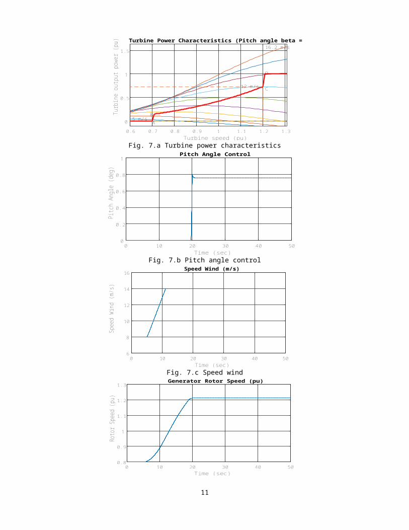
The simulation results for output wind turbine are shown in Figs. 7.a, 7.b, 7.c and 7.d. These curves represent the turbine power characteristics (turbine output power versus turbine speed), pitch angle, wind speed and mechanical angular velocity. It is obvious that at t= 5 sec PI controller is set to start, there are a strong variation in the rotor speed from 0.8 pu to 1.22 pu du to the variations of wind speed from 8 to 14 m/s as shown in Figs. 7.c and 7.d. The wind speed curve as shown in Fig. 7.c represents a rise in wind speed within the interval for 5 to 12 second. So, an automatic rise in pitch angle from zero to 0.78 as well as the rotor speed followed. The graph of pitch angle is controlled to overcome the speed variation and oscillation. Figs. 8.a, 8.b, 8.c and 8.d show the DC voltage, active power, reactive power and mechanical torque. Fig. 8.a shows the DC voltage is constant at t= 20 second, active power as shown in Fig. 8.b is variation between 2 to 9 MW and constant at 9MW. While reactive power as shown in Fig. 8.c is varied between -0.02 to -0.68 MVAR and then became constant at -0.68 MVAR. In Fig. 8.d the torque is constant after 20 second at 0.73 pu. Furthermore, Figs. 9.a, 9.b, 9.c, 9.d, 9.e and 9.f show the current plant, voltage plant, the active and reactive power generated. As well as speed motor and voltage bus generated. The first two sub-Figs. 9.a and 9.b the current and voltage generated, the current is constant at 0.9665 pu and voltage is constant at 0.9972 pu. The active power exhibits some strong oscillations within the range of -6 to 0.5 MW. The reactive power is constantly at 1.3 MVAR at t= 19 second. While the graph of speed motor is constant at t=20 second and equal 0.9933pu. Finally voltage bus of grid is constant at 1.0014 at t=20 second.
8

Turbine speed (pu)0.6 0.7 0.8 0.9 1 1.1 1.2 1.3
Turb
ine
outp
ut p
ower
(pu)
0
0.5
1
1.5
5 m/sA
B
C12 m/s
D
16.2 m/sTurbine Power Characteristics (Pitch angle beta = 0 deg)
Fig. 7.a Turbine power characteristics
Time (sec)0 10 20 30 40 50
Pitch
Ang
le (d
eg)
0
0.2
0.4
0.6
0.8
1Pitch Angle Control
Fig. 7.b Pitch angle control
Time (sec)0 10 20 30 40 50
Spee
d W
ind
(m/s
)
6
8
10
12
14
16Speed Wind (m/s)
Fig. 7.c Speed wind
Time (sec)0 10 20 30 40 50
Roto
r Spe
ed (p
u)
0.8
0.9
1
1.1
1.2
1.3Generator Rotor Speed (pu)
Fig. 7.d Rotor speed
9

Time (sec)0 10 20 30 40 50
DC
Vol
tage
(vol
t)1199.5
1200
1200.5
1201
1201.5
1202 Wind Turbine output DC Voltage
Fig. 8.a Wind turbine DC voltage
Time (sec)0 10 20 30 40 50
Activ
e Po
we
(MW
)
0
2
4
6
8
10 Wind generated Active Power (MW)
Fig. 8.b Wind turbine ative power
Time (sec)0 10 20 30 40 50
Reac
tive
Powe
r (M
VAR)
-0.7
-0.6
-0.5
-0.4
-0.3
-0.2
-0.1
0Wind Reactive Power (MVAR)
Fig. 8.c Wind turbine reactive power
Torque (pu)0 10 20 30 40 50
Tim
e (s
ec)
-0.9
-0.8
-0.7
-0.6
-0.5
-0.4
-0.3
-0.2Mechanical Torque Applied to Generator (pu)
Fig. 8.d Mechanical torque
10
Time (sec)0 10 20 30 40 50
Cur
rent
(pu)
0.96
0.962
0.964
0.966
0.968
0.97
0.972
0.974Current Plant (pu/2MVA)
Fig. 9.a Current plant
Time (sec)0 10 20 30 40 50
Volta
ge (p
u)
0.997
0.9975
0.998
0.9985
0.999
0.9995
1Voltage Plant (pu)
Fig. 9.b Voltage plant
Time (sec)0 10 20 30 40 50
Activ
e Po
wer
(MW
)
-7
-6
-5
-4
-3
-2
-1
0
1Active Power for Bus 25Kv
Fig. 9.c Wind turbine active power
Time (sec)0 10 20 30 40 50
Reac
tive
Powe
r (M
VAR)
-0.2
0
0.2
0.4
0.6
0.8
1
1.2
Reactive Power for Bus 25Kv
Fig. 9.d Wind turbine reactive power
11

Time (sec)0 10 20 30 40 50
Spe
ed M
otor
(pu)
0.993
0.9932
0.9934
0.9936
0.9938
0.994Speed Motor (pu)
Fig. 9.e Speed motor
Time (sec)0 10 20 30 40 50
Volta
ge (p
u)
1
1.0005
1.001
1.0015
Voltage Bus (pu)
Fig. 9.f Wind turbine voltage bus
6. ConclusionThis paper presents a model and simulation of variable speed wind turbine using DFIG under Matlab/Simulation. The model of a wind turbine-generator system equipped with a doubly-fed induction generator which is developed in a Matlab/Simulink environment. It simulates the dynamics of the system from the turbine rotor, where the kinetic wind energy is converted to the mechanical energy, to the generator, which transforms the mechanical power to electrical power, and then to the grid connection point, where the electric power is fed into the grid. An analytical model of wind turbine was presented and power coefficient characteristics were investigated. Furthermore, a graphical model of 6 MW wind farm was built with enhanced control of speed using PI controller with MBA algorithm. At first when the control system was not applied, the rotor speed was very unstable but after 5s and also due to a perfect tuning of the PI controller with MBA algorithm, results were the best in terms of stability of the rotor speed versus the wind variation. The rotor speed was merely constant after 20s despite the wind speed was still varying within the range of 5m/s to 12m/s. On the other hand, the voltage generated as well as the reactive and active powers were also good performance.
7. References[1]. R. Datta and V. T. Ranganathan, “Variable-speed wind power generation using doubly fed wound rotor induction – a comparison with alternative schemes‟ IEEE Trans. Energy Conversion, vol. 17, no. 3, pp. 414-421, Sept. 2002.[2]. A. Larsson, ―Flicker emission of wind turbines during continuous operation,‖ IEEE Trans. Energy Conversion, vol. 17, no. 1. pp. 114-118, Mar. 2002.[3]. W.L Kling, H. Polinder, J.G. Slootweg, "Dynamic modeling of a wind turbine with doubly fed induction generator." Power engineering Society Summer Meeting. Vancouver, Canada. July 2001. [4]. M. V. A. Nunes, J. A. P. Lopes, H. H. Zurn, U. H. Bezerra, R. G. Almeida, ―Influence of the variable-speed wind generators in transient stability margin of the conventional generators integrated in electrical grids,‖ IEEE Trans. Energy Conversion, vol. 19, no. 4, pp. 692-701, Dec. 2004
12

[5]. Carles Batlle, Arnau Do` ria-Cerezo, Romeo Ortega. “Power Flow Control of a Doubly-Fed Induction Machine Coupled to a Flywheel”. European Journal of Control (2005)11:1–13, 2005 EUCA. [6]. Simulation Based Study of Doubly Fed Induction Generators for Wind Electric Generation Using Matlab/Simulink”. International Journal of Engineering and Innovative Technology (IJEIT) Volume 1, Issue 3, March 2012.[7]. Branislav Dosijanoski. “Simulation of Doubly-Fed Induction Generator in a Wind Turbine”. XI International PhD Workshop OWD 2009, October 2009. Revue des Energies Renouvelables Vol. 11 No3 (2008) 453 – 464.[8]. Ashwani Kumar, Sanjay K. Jain. “A Review on the Operation of Grid Integrated Doubly Fed Induction Generator”. International Journal of Enhanced Research in Science Technology & Engineering, Vol. 2 Issue 6, June-2013, pp: (25-37).[9]. Richard Gagnon, Gilbert Sybille, Serge Bernard, Daniel Paré, Silvano Casoria, Christian Larose. “ Modeling and Real-Time Simulation of a Doubly-Fed [10]. G. D. Marques, M. F. Iacchetti. “Control Method of the DFIG Connected to a DC Link through a Diode Bridge”. Energy and Power Engineering, 2013, 5, 102-108.[11]. Ankit Gupta, S.N. Singh, Dheeraj K. Khatod. “Modeling and Simulation of Doubly Fed Induction Generator Coupled With Wind Turbine-An Overview”. Journal of Engineering, Computers & Applied Sciences (JEC&AS) ISSN No: 2319-5606 Volume 2, No.8, August 2013.[12]. Amevi Acakpovi, Essel Ben Hagan. “A Wind Turbine System Model using a Doubly-Fed Induction Generator (DFIG)”. International Journal of Computer Applications (0975 – 8887) Volume 90 – No 15, March 2014.[13]. B.Chitti Babu , K.B.Mohanty. “Doubly-Fed Induction Generator for Variable Speed Wind Energy Conversion Systems- Modeling & Simulation”. International Journal of Computer and Electrical Engineering, Vol. 2, No. 1, February, 2010 1793-8163 141. [14]. J.S. Lather, S.S Dhillon, S.Marwaha. “MODERN CONTROL ASPECTS IN DOUBLY FED INDUCTION GENERATOR BASED POWER SYSTEMS: A REVIEW”. International Journal of Advanced Research in Electrical, Electronics and Instrumentation Engineering Vol. 2, Issue 6, June 2013. [15]. A. Dendouga , R. Abdessemed, M. L. Bendaas and A. Chaiba. “Decoupled Active and Reactive Power Control of a Doubly-Fed Induction Generator (DFIG)”. Proceeding of the 15th Mediterranean Conference on Control & Automation, July 27 – 29, 2007, Athens – Greece.[16]. S. Engelhardt, I. Erlich, C. Feltes, J. Kretschmann, F. Shewarega, ―Reactive Power Capability of Wind Turbines Based on Doubly Fed Induction Generator,‖ IEEE Trans. on Energy Conversion, vol. 26, no. 1, pp. 364-372, March 2011.17].Amevi Acakpovi, Essel Ben Hagan. “A Wind Turbine System Model using a Doubly-Fed Induction Generator (DFIG)”. International Journal of Computer Applications (0975 – 8887) Volume 90 – No 15, March 2014. Accra Institute of Technology – Ghana.[18].Amevi Acakpovi, Essel Ben Hagan. “A Wind Turbine System Model using a Doubly-Fed Induction Generator (DFIG)”. International Journal of Computer Applications (0975 – 8887) Volume 90 – No 15, March 2014. Accra Institute of Technology – Ghana.[19]. G. D. Marques, M. F. Iacchetti. “Control Method of the DFIG Connected to a DC Link through a Diode Bridge”. Energy and Power Engineering, 2013, 5, 102-108. [20]. Ankit Gupta, S.N. Singh, Dheeraj K. Khatod. “Modeling and Simulation of Doubly Fed Induction Generator Coupled With Wind Turbine-An Overview”. Journal of Engineering, Computers & Applied Sciences (JEC&AS) ISSN No: 2319-5606 Volume 2, No.8, August 2013.[21]. Bo Gu, Xinyu Liu, Yan Ren and Yanpin Li. “Research Doubly-fed Induction Generator Dynamic Characteristics Based on Time-varying Parameters”. International Journal of Control and Automation Vol.6, No.5. 2013 pp. 159-170. turbines,‖ IEEE, Industry Applications Magazine, vol. 8, iss. 3, pp. 26-33, May/June 2002.
13