Embed Size (px)
Citation preview

Paper Review:Area-Performance Trade-offs in
Tiled Dataflow Architectures
Ke PengInstructor: Chun-Hsi Huang
CSE 340 Computer Architecture
University of Connecticut

2/33
Reference
Steven Swanson, Andrew Putanm, Martha Mercaldi, Ken Michelson, Andrew Petersen, Andrew Schwerin, Mark Oskin, Susan J. Eggers
Computer Science & Engineering, University of Washington
“Area-Performance Trade-offs in Tiled Dataflow Architectures”
Proceedings of the 33rd International Symposium on Computer Architecture, 2006 IEEE.
3/33
Outline
Background Introduction
Experimental Infrastructure
WaveScalar Architecture
Evaluation
Conclusion

4/33
Background Introduction
A lot of issues should be addressed in processor design
Wire delayFabrication reliabilityDesign complexity
Processing elements (PEs) are designed and replicated across a chip
Examples of titled architecturesRAWSmartMemoriesTRIPSWaveScalar

5/33
Background Introduction
Tiled WaveScalar Architecture
Captured online, University of Washington

6/33
Background Introduction
Benefits PE design Decreases design and verification timeProvide robustness for fabrication errorsReduce wire delay for data and control signal transmission
Good performance is achievable only if all aspects of the microarchitecture are properly designed.
ChallengesTile number VS Tile sizeHigh utilized tiles VS Possibly more powerful tilesPartition and distribution of data memory across the chipTiles interconnectionEtc.

7/33
Background Introduction
This paper focuses on WaveScalar processor, explores the area-performance trade-offs encountered when designing a tiled architecture.
WaveScalar, tiled dataflow architectureBased on PE replicationHierarchical data networksDistributed hardware data structures, including the caches, store buffers, and specialized dataflow memories (token store).

8/33
Experimental Infrastructure
Synthesizable RTL WaveScalar model
TSMC (Taiwan Semiconductor Manufacturing Company) 90 nm technology
Use Synopsys DesignWare IP
Synopsys Design Compiler for front-end synthesis
Cadence First Encounter for back-end synthesis
Synopsys VCS for RTL simulation and function verification
Hierarchical architecture and single voltage design, can be extended for multiple voltage design.

9/33
Experimental Infrastructure
Three workloads to evaluate the WaveScalar processor
Spec2000 benchmark suite (ammp, art, equake, gzip, twolf and mcf), for single-threaded performance evaluation
Mediabench (rawdaudio, mgeg2encoder, djpeg), for media processing performance evaluation
Splash2 benchmarks(fft, lu-continuous, ocean-noncontinuous, raytrace, water-spatial, radix), for multiple-threaded performance evaluation

10/33
WaveScalar Architecture
Processing Elements (PEs)
PE is the heart of a WaveScalar machine.
Execution resources
(Captured from Steven ISCA’06)

11/33
WaveScalar Architecture
Five pipeline stages of PEInput stage:
Operand messages arrive at the PE either from itself or another PE.
Match stage: Operands enter the matching table, determing which instructions are ready to fire, issuing table index of eligible instructions into instruction scheduling queue.
Dispatch stage: Selects instruction from scheduling queue, reads operands from matching table for executing.
Execute state: Executes an instruction
Output stage: Send output to its consumer instructions via connection network.

12/33
WaveScalar Architecture
Several PEs are combined into a single Podshare bypass networks
Several pods are combined into a single Domain
Several Domains are combined into a single cluster
These are parameters that affect the performance and area trade-off of WaveScaler.
2-PE pod is 15% faster on average than isolated PEsIncreasing the number of PEs in each pod with further increase performance but adversely affects cycle time.
13/33
WaveScalar Architecture
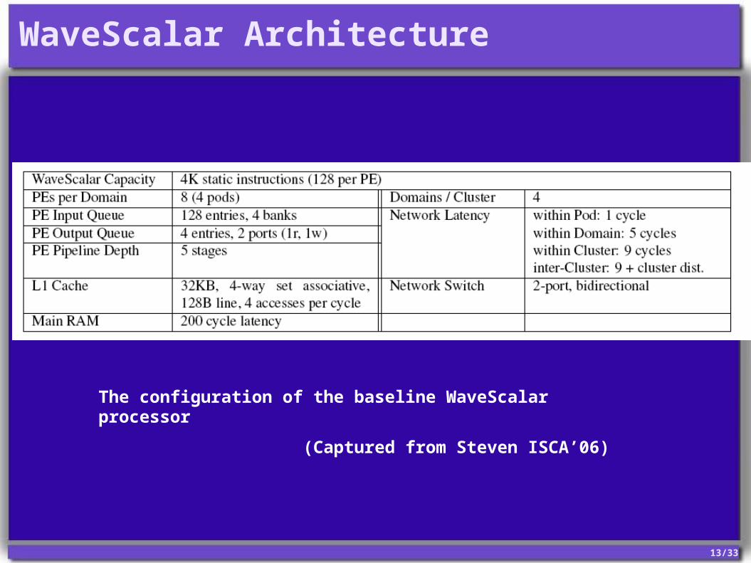
The configuration of the baseline WaveScalar processor
(Captured from Steven ISCA’06)
14/33
WaveScalar Architecture
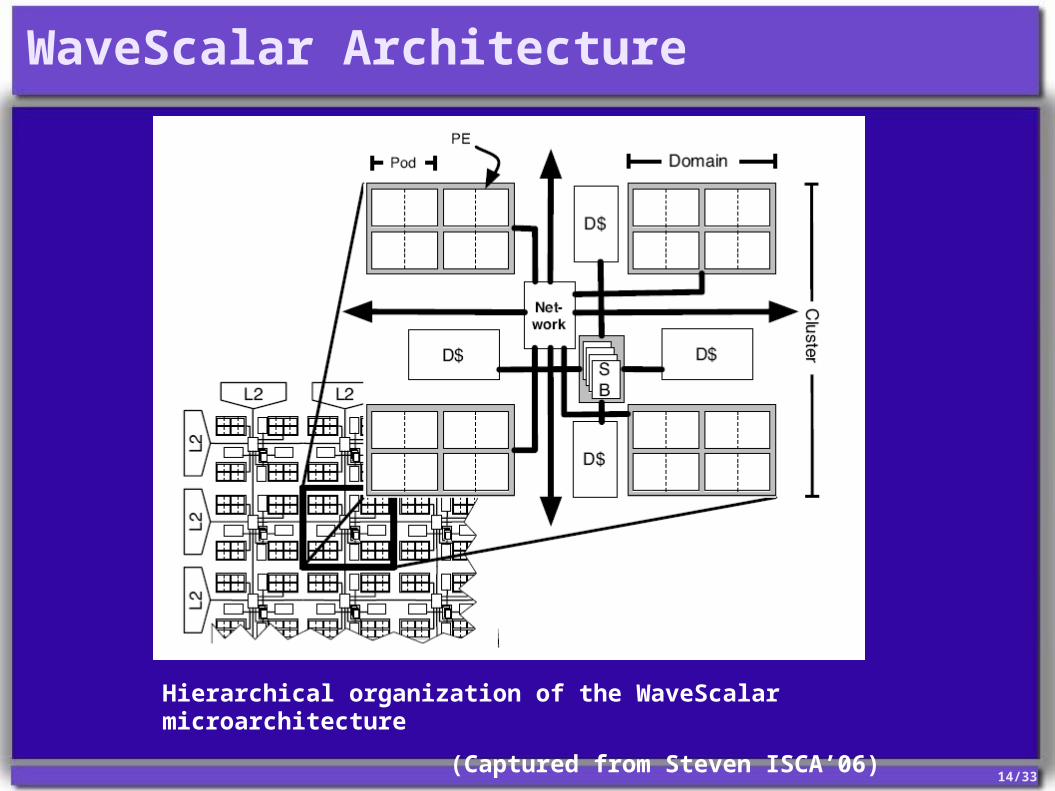
Hierarchical organization of the WaveScalar microarchitecture
(Captured from Steven ISCA’06)

15/33
WaveScalar Architecture
4 Levels hierarchical interconnect network
Intra-pod
Intra-domainBroadcast-basedPseudo-PEs (Mem, Net), serve as gateways to the memory system and PEs in other domains or clusters.7% area overhead
Intra-clusterSmall network, area overhead negligible
Inter-clusterResponsible for all long-distance communication1% of the total chip area overhead

16/33
WaveScalar Architecture
Hierarchical cluster interconntects
(Captured from Steven ISCA’06)

17/33
WaveScalar Architecture
Memory Subsystem
Wave-ordered store buffersMemory interface that enables WaveScalar to execute programs written in imperative languages (C, C++, Java)Store decoupling technique to process store address and store data messages separatelyPartial store queues for storing addressOccupies approximately 6.2% area of the cluster
Conventional memory hierarchy with distributed L1 and L2 cache
L1 data cache is 4-way set associative and have 128-byte lines, with hit costs 3-cyclesL2’s hit rate is 20-30 cyclesMain memory latency is modeled at 200 cycles

18/33
Evaluation
Die area spent for the baseline design
(Captured from Steven ISCA’06)

19/33
Evaluation
The configuration of the baseline WaveScalar processor
(Captured from Steven ISCA’06)

20/33
Evaluation
Many parameters affect the area required for WaveScalar designs.
This paper considers 7 parameters with the strongest effect on the area requirements.
Ignores some minor effects.For example, assuming that wiring costs do not decrease with fewer than 4 domains.

21/33
Evaluation
WaveScalar processor area model
(Captured from Steven ISCA’06)

22/33
Evaluation
The ranges allow for over 21,000 Wavescalar processor configurations.
To select the configurations, the authors:Eliminate clearly poor, unbalanced designsBound die size at 400mm2 in 90 nm technology
Reduce the number of designs to 201
Report AIPC (Alpha-equivalent instructions executed per cycle) instead of IPC.

23/33
Evaluation
Pareto-optimal WaveScalar Designs
(Captured from Steven ISCA’06)

24/33
Evaluation
Pareto-optimal configurations for Splash2
(Captured from Steven ISCA’06)

25/33
Evaluation
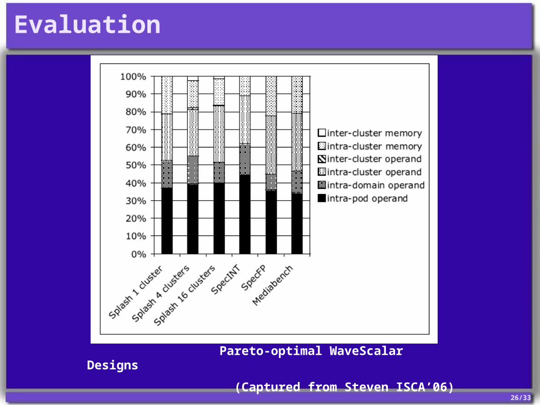
Goal of WaveScalar’s hierarchical interconnect:Isolate as much traffic as possible in the lower levels of the hierarchy, within a PE, a pod or a domain.
On average, 40% network traffic remains within a pod
52% network traffic remains within a domain
On average, just 1.5% of traffic traverses the inter-cluster interconnect
26/33
Evaluation
Pareto-optimal WaveScalar Designs
(Captured from Steven ISCA’06)
27/33
Conclusion
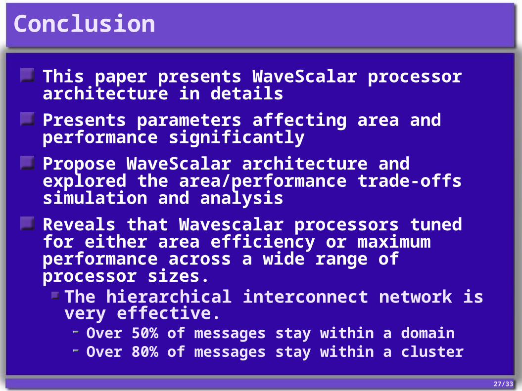
This paper presents WaveScalar processor architecture in details
Presents parameters affecting area and performance significantly
Propose WaveScalar architecture and explored the area/performance trade-offs simulation and analysis
Reveals that Wavescalar processors tuned for either area efficiency or maximum performance across a wide range of processor sizes.
The hierarchical interconnect network is very effective.
Over 50% of messages stay within a domain Over 80% of messages stay within a cluster

28/33
Thank you!