Embed Size (px)
Citation preview
Pandora would like to thank you for choosing our DXL 1840L service and security system
Pandora DXL 1840L is a premium car service-security system, built for cars with on-board voltage of 12V. It is a complex engineering solution which includes car security system, telemetry, remote and automatic engine start and various service options, all controlled from your OEM key remote, smart-phone or online service.
When building Pandora DXL 1840L we were using the most up-to-date electronics from world’s best manufacturers. The device is built using high-precision mounting and control machinery, thus we guarantee highest possible quality, reliability and stable technical characteristics for the whole opera-tion period.
Pandora DXL 1840L has a cryptographically strong authorization code with unique dialog algo-rithm and individual 128 bit encryption key on every device. We guarantee 100% protection form elec-tronic hacking for the whole operation period.
The system is built for your convenience: it’s ergonomic, reliable, has the highest security and service characteristics, 3 years unconditional warranty and free service and support on the territory of Russain Fed-eration and nearest states. We are happy to provide any support we can – feel free to use our online support.
This device has limited external factors resistance. It should not be subjected to water beyond occasional splatter, or operated intemperatures outside -40 to +80° C range. All system components must be installed only in a car interior..
IMPORTANT! Note that this manual describes remote and manual functions for the most part. Functionality of the system is vast and would require a book-sized manual to fully describe. Instead we use handy software named AlarmStudio that functions as both programming tool and an extended installation & functionality manual. It requires Windows and can be downloaded at pandorainfo.com
Product is in conformity with Electromagnetic CompatibilityDirective EMC 2004/108/EC and R&TTE Directive 1999/5/EC
Our web site: www.pandorainfo.comCustomer support: [email protected]
WARNING! IT IS STRONGLY ADVISED TO HAVE PROFESSIONAL CAR MECHANIC INSTALLING THE SYSTEM. ANY CAR ELECTRONICS INSTALLER SHOULD BE ABLE TO INSTALL PANDORA DXL 1840L USING INSTALLATION SCHEME IN THIS MANU-AL AND ALARMSTUDIO SOFTWARE. MOST FEATURES ARE HIGHLY DEPENDENT ON COMPETENT INSTALLATION. OUR SYSTEMS ARE THOROUGHLY TESTED FOR QUALITY, SO IF A FEATURE FAILS TO PRODUCE EXPECTED RESULTS, MOST LIKELY THE PROBLEM IS IN IMPROPER INSTALLATION

32 USER MANUALPANDORA DXL 1840L CAR SERVICE-SECURITY SYSTEM
Information 40Siren sounds and turn light signals 40Service sound signals of the «Beeper» 40Meaning of indicator LED colors 41Checking the number of recorded radio tags/mobile device 41System modules layout 42Warranty obligations 43Installation certificate 44Acceptance certificate 45Warranty card 45
Table of contents
System features 4Car security zones 5System set 5
Control over the system 6 Arming/disarming using radio tag button 6Arming/disarming in Hands Free mode 6Arming/disarming in «Slave» mode 6Immobilizer mode 7Anti-Hi-Jack-1 mode 7Anti-Hi-Jack-2 mode 8 Code immobilizer using original car controls 8Maintenance mode 8Replacing immobilizer tag battery 9Control over the system in case of emergency 10Emergency disarming using VALET button 10Enabling/disabling immobilizer radio tag 12
Control over the system via a phone 13DTMF – commands 13Changing settings via phone 16
Online service and mobile application 18
Installation and configuration of the system 23Installation requirements 23 Wiring diagram 24Wiring description 26Programming the systems 28Preparing to program the system using a computer 29Updating firmware 30Programming using VALET button 30Additional devices 39

54 USER MANUALPANDORA DXL 1840L CAR SERVICE-SECURITY SYSTEM
System feature
Base unit• Android and iOS applications.• Individual PIN-code to disarm and switch off immobilizer.• Hands Free mode for arming/disarming.• 2 Antihijack modes.• Automatic arming• Validator mode• Algorithms of original immobilizer bypass.• Integrated GSM-interface.• Built-in 2,4 GHz module with support of Bluetooth 4.2 Low Energy protocol.• Dialog coding of control commands.• Individual 128-bit encryption key.• Built-in integral accelerometer for determining motion and shocks with adaptive processing algorithm and sensitivity controls.• Advanced process of sensor data reading, eliminating false alarm possibilities• Built-in temperature sensor.• Firmware updates via built-in micro-USB socket.• Support for additional devices: digital blocking relay BM-105, blocking radio relay BTR-101,radio hood module RHM-03BT, wireless door sensor DMS-100BT, GPS/GLONASS receiver NAV-035 BT.
Bluetooth tag• Dialog coding of control commands.• Individual 128-bit encryption key.• Built-in LED indicator.• Built-in button to control over security modes.• Built-in integral accelerometer.
Car security zones
Pandora DXL 1840L service-security system guards following independent zones:• car doors perimeter • front hood triggers
* - Availability of this function depends on car make and model
• trunk triggers • ignition trigger • brake pedal pressing• triggering of the built-in shock sensor (warning level)• triggering of the built-in shock sensor (alarm level)• triggering of the built-in motion sensor• triggering of the built-in tilt sensor• critically low on-board voltage• parking lights left on notification when arming*.
System set
Base unit 1Bluetooth tag 2Cable with VALET button and three-colored light indicator 1User installation manual 1Plastic card with individual secret code 1Engine temperature sensor 1Beeper 1Main cable of the base unit 1Additional cable of the base unit 1Analog blocking relay 1IMMO-KEY interface cable 1Fastening kit 1Packaging 1Manufacturer reserves the right to change set and construction of the product to improve its technological and operational
parameters without notification.
76 USER MANUALPANDORA DXL 1840L CAR SERVICE-SECURITY SYSTEM
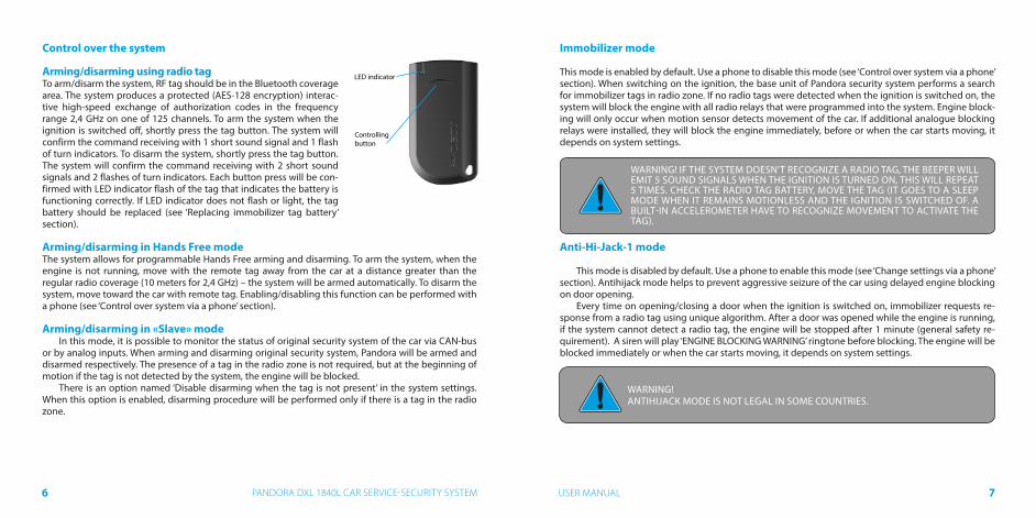
Immobilizer mode
This mode is enabled by default. Use a phone to disable this mode (see ‘Control over system via a phone’ section). When switching on the ignition, the base unit of Pandora security system performs a search for immobilizer tags in radio zone. If no radio tags were detected when the ignition is switched on, the system will block the engine with all radio relays that were programmed into the system. Engine block-ing will only occur when motion sensor detects movement of the car. If additional analogue blocking relays were installed, they will block the engine immediately, before or when the car starts moving, it depends on system settings.
WARNING! IF THE SYSTEM DOESN’T RECOGNIZE A RADIO TAG, THE BEEPER WILL EMIT 5 SOUND SIGNALS WHEN THE IGNITION IS TURNED ON, THIS WILL REPEAT 5 TIMES. CHECK THE RADIO TAG BATTERY, MOVE THE TAG (IT GOES TO A SLEEP MODE WHEN IT REMAINS MOTIONLESS AND THE IGNITION IS SWITCHED OF. A BUILT-IN ACCELEROMETER HAVE TO RECOGNIZE MOVEMENT TO ACTIVATE THE TAG).
Anti-Hi-Jack-1 mode
This mode is disabled by default. Use a phone to enable this mode (see ‘Change settings via a phone’ section). Antihijack mode helps to prevent aggressive seizure of the car using delayed engine blocking on door opening.
Every time on opening/closing a door when the ignition is switched on, immobilizer requests re-sponse from a radio tag using unique algorithm. After a door was opened while the engine is running, if the system cannot detect a radio tag, the engine will be stopped after 1 minute (general safety re-quirement). A siren will play ‘ENGINE BLOCKING WARNING’ ringtone before blocking. The engine will be blocked immediately or when the car starts moving, it depends on system settings.
Control over the system
Arming/disarming using radio tagTo arm/disarm the system, RF tag should be in the Bluetooth coverage area. The system produces a protected (AES-128 encryption) interac-tive high-speed exchange of authorization codes in the frequency range 2,4 GHz on one of 125 channels. To arm the system when the ignition is switched off, shortly press the tag button. The system will confirm the command receiving with 1 short sound signal and 1 flash of turn indicators. To disarm the system, shortly press the tag button. The system will confirm the command receiving with 2 short sound signals and 2 flashes of turn indicators. Each button press will be con-firmed with LED indicator flash of the tag that indicates the battery is functioning correctly. If LED indicator does not flash or light, the tag battery should be replaced (see ‘Replacing immobilizer tag battery’ section).
Arming/disarming in Hands Free modeThe system allows for programmable Hands Free arming and disarming. To arm the system, when the engine is not running, move with the remote tag away from the car at a distance greater than the regular radio coverage (10 meters for 2,4 GHz) – the system will be armed automatically. To disarm the system, move toward the car with remote tag. Enabling/disabling this function can be performed with a phone (see ‘Control over system via a phone’ section).
Arming/disarming in «Slave» modeIn this mode, it is possible to monitor the status of original security system of the car via CAN-bus
or by analog inputs. When arming and disarming original security system, Pandora will be armed and disarmed respectively. The presence of a tag in the radio zone is not required, but at the beginning of motion if the tag is not detected by the system, the engine will be blocked.
There is an option named ‘Disable disarming when the tag is not present’ in the system settings. When this option is enabled, disarming procedure will be performed only if there is a tag in the radio zone.
WARNING! ANTIHIJACK MODE IS NOT LEGAL IN SOME COUNTRIES.

98 USER MANUALPANDORA DXL 1840L CAR SERVICE-SECURITY SYSTEM
Anti-Hi-Jack-2 mode
This mode is disabled by default. Use Pandora AlarmStudio application to enable this mode. Anti-Hi-Jack-2 mode helps to prevent aggressive seizure of the car using delayed engine blocking on radio tag disappearance. The system requests a response from a tag using a unique algorithm when the ignition is switched on. If the system cannot detect a radio tag, the engine will be stopped after 1 minute (gen-eral safety requirement for car movement). «Engine blocking warning» ringtone will play from siren and beeper before blocking. When warning signals end, the system will block the engine. Engine blocking will occur immediately or when the car starts moving, it depends on block implementation and system settings.
Code immobilizer using original car controls
Code immobilizer (validator) is a function that allows disarming, disabling blocking and controlling tim-er channels using original car controls (button, lever or pedal). To enter immobilizer code, programmed button (lever, pedal) should be pressed a number of times equals the first digit of the code. Pauses between presses should not exceed 1 second. Pauses more than 1 second will be interpreted as the start of next digit input. Immobilizer code can consist max of 4 digits from 1 to 9.After entering a correct immobilizer code, depending on the settings, either the engine blocking will be lifted or a programmed timer channel will be activated or the system will be disarmed.
Maintenance (Valet) mode
It is recommended to put system into maintenance mode before handing it to the car service or valet parking. When this mode is switched on, security system stops interfering with built-in electronics and disables all functions to ease maintenance or parking. Moreover, you will not have to leave the remote control or radio tag to the valet or the mechanic. You can enable/disable this mode using a radio tag, mobile phone or immobilizer button (if the ‘Code immobilizer’ function is implemented).
Enable/Disable the maintenance mode using a radio tag:To enable/disable the maintenance mode, the radio tag should be in the coverage zone. Enter the
‘Immobilizer PIN-code’ (if the ‘Code immobilizer’ function is implemented). Press and hold the button on the tag for 3 seconds to enable the maintenance mode.
Press and hold the button on the tag for 3 seconds again to disable the maintenance mode.
Enable/Disable the maintenance mode using a phone:To enable the maintenance mode, disarm the system, switch on the ignition, the radio tag should
be in the coverage zone (if the immobilizer/AntiHijack function is activated), enter the ‘Immobilizer PIN-code’ (if the ‘Code immobilizer’ function is implemented). Call the system number. Wait for answer.
• To enable maintenance mode, dial “Enable maintenance mode“ DTMF command 551* • Enter the ‘Secret PIN-code’ that is located on the owner’s plastic card – the maintenance mode will
be activated.• To disable maintenance mode, dial 552* DTMF command.
Enable/Disable the maintenance mode using an immobilizer button:To enable the maintenance mode, disarm the system, switch on the ignition, the radio tag should
be in the coverage zone (if the immobilizer/AntiHijack function is activated), enter the ‘Immobilizer PIN-code’ (if the ‘Code immobilizer’ function is implemented) and press the same button 10 times within 20 seconds after entering the PIN-code. To disable maintenance mode switch on the ignition and enter the ‘Immobilizer PIN-code’.
Replacing immobilizer tag battery:
Carefully open the cover of the tag’s battery compartment. Extract discharged battery and insert a new one keeping in mind the correct polarity. Replacing a battery will not cause a loss of tag code information, as authorization data is stored in the non-volatile memory of the MCU.Carefully close the cover of the tag’s battery compartment. All elements of construction should be rigidly locked in places. If it is so, the tag can be operated as usually.
Open here

1110 USER MANUALPANDORA DXL 1840L CAR SERVICE-SECURITY SYSTEM
Control over the system in case of emergency
Use a phone to deactivate the system quickly. To disarm the system via a phone, call the system’s number. When it answers, dial command 0*. If the call is not made from the owner’s number, guest PIN-code should be entered. Factory set guest PIN-code is 1-2-3-4.
To switch off an immobilizer tag, dial the 998* command (after dialing, enter the ‘Secret PIN-code’ that is located on the owner’s plastic card). To switch on an immobilizer tag, dial the 888*command. If the system cannot be deactivated via a phone, apply emergency disarming and switching on/off an immobilizer tag using VALET button.
Emergency disarming using «VALET» button
In case you cannot disarm the system using a phone or immobilizer tag, the ‘Secret PIN-code’ can be used. The ‘Secret PIN-code’ is written on the owner’s plastic card under protective layer. Erase the protective layer and use VALET button to input the PIN-code.
The code must be entered only when the base unit is powered and the ignition is switched off. The PIN-code can be entered using external or located on the base unit VALET button. The digits input and correct input is indicated by the external or located on the base unit LED indicator.
Entering the PIN-code
• Enter the first digit of the code using VALET button. Press the button a number of times, equals to the first digit. Pauses between presses should not exceed 1 second. Each pressing will be confirmed with an orange LED indicator flash. A Pause for more than 1 second and a red LED indicator flash confirm the input of the first digit. Then you can enter the next digit.
• Enter the second digit of the code using VALET button. Press the button a number of times, equals to the second digit. Pauses between presses should not exceed 1 second. Each pressing will be confirmed with an orange LED indicator flash. A Pause for more than 1 second and a red LED indicator flash confirm the input of the second digit. Then you can enter the next digit.
• Enter the third digit of the code using VALET but-ton. Press the button a number of times, equals to the third digit. Pauses between presses should not exceed 1 second. Each pressing will be confirmed with an orange LED indicator flash. A Pause for more than 1 second and a red LED indicator flash confirm the input of the third digit. Then you can enter the next digit.
• Enter the fourth digit of the code using VALET but-ton. Press the button a number of times, equals to the fourth digit. Pauses between presses should not exceed 1 second. Each pressing will be confirmed with an or-ange LED indicator flash.
The system will confirm correct PIN-code with the series of red and green flashes and the system will be disarmed. If the input was incorrect, it will be indicated with a red LED indicator flash and the system will stay in a previous state. New input can be attempted after 5 seconds.
If the system was disarmed and the ignition was switched off it will enter programming mode after correct input of the PIN-code.
For emergency arming when the ignition is switched off, press and hold VALET button for 3 sec-onds. The system will be armed in 30 seconds. Status LED indicator is lighting red during the countdown.
2-2-2-2
PIN
Three-color status LED indicator (green, red, orange)
VALET button
VALET BUTTON
WARNING! MAKE SURE THAT A PROTECTIVE LAYER ON THE OWNER’S PLASTIC CARD IS INTACT AFTER THE INSTALLATION OF THE SYSTEM. THE PLASTIC CARD HOLDS THE ‘SECRET PIN-CODE’.
WARNING! CAREFULLY REMOVE THE PROTECTIVE LAYER, DO NOT USE SHARP OBJECTS TO AVOID DAMAGING OF HIDDEN INFORMATION UNDER A PROTEC-TIVE LAYER.

1312 USER MANUALPANDORA DXL 1840L CAR SERVICE-SECURITY SYSTEM
Enabling/Disabling immobilizer radio tag
Write down or remember the ‘Service PIN-code’
To disable immobilizer radio tag, enter level 15 (the system should be in programming mode). Enter the ‘Secret PIN-code’ to disable radio tag or press VALET button once to enable radio tag.
Enter the “Service PIN-code” to enter programming mode (factory preset of the service PIN-code is ‘1-1-1-1’). You can enter the code only if the base unit is powered, the ignition is switched off, the system is disarmed and the maintenance mode is switched off. If there is no ‘Service PIN-code’, you can enter programming mode using the ‘Secret PIN-code’ written on the owner’s card. After entering programming mode, press VALET button 15 times. Green color of LED indicator means a radio tag is switched on, red color means a radio tag is switched off.
Disabling radio tag:LED indicator will light green after entering the programming level. The system will wait for en-
tering the ‘Secret PIN-code’. Enter the ‘Secret PIN-code’ that is written on the owner’s plastic card. The system will confirm disabling of the radio tag with two sound signals of the siren and a long red LED flash. After that the system will return to the programming menu. If the PIN-code is not entered within 10 seconds or the input is incorrect, a siren will sound one signal, LED will produce the series of red and green flashes and the system will return to the programming menu.
Enabling radio tag:LED indicator will light red after entering the programming level. The system will wait for action.
Press VALET button once to enable radio tag. The system will confirm enabling with one short sound signal of a siren and a green LED light. After that the system will return to the programming menu.
Control over the system via a phone
Call the system’s phone number. When it answers, enter a command code.
DTMF – commands. For example: To have simple access to engine start function, create a new contact in the contactlist of your phone, name it ‘Engine start’, for instance, and add the number in the following format:+XXXXXXXXXXX,123*,297* where ‘+XXXXXXXXXXX’ – the system phone number, ‘,’ - pause is a feature of the phone (can be displayed as the ‘P’, see the instructions of the phone), ‘123*’ - remote engine start DTMF command,
##
99 **
**
9900 **
11 00 00 **11 22 33 **
Return to previous menu state
Repeat the last message
Silent arming
Help
0000 **
0011 **Silent disarming
11 ** Arming00 ** Disarming
Event history5511 ** Tow truck mode
Request GSM account balance
Start the engine/prolong heating33 22 11 ** Stop the engine
33 33 33 ** Switch on add. function using F via CAN55 00 00 **44 55 66 **66 55 44 **
66 66 66 **99 99 99 **22 55 88 ** System information
Request current coordinates
Switch on additional channel
Switch o� additional channel
11 55 66 **66 55 11 **
Switch on engine preheater
Switch o� engine preheater
Enable engine blocking
Disable engine blocking
99 99 88 ** Disable immobilizer tag
88 88 88 ** Enable immobilizer tag22 22 22 ** Disable Hands Free mode
22 22 33 ** Enable Hands Free arming
22 22 44 ** Enable Hands Free disarming 22 22 55 ** Enable Hands Free disarming only with autom. start77 88 99 ** Enable automatic engine start
99 88 77 ** Disable automatic engine start22 99 77 ** Call ended
55 55 11 ** Enable maintenance mode (see description below)55 55 22 ** Disable maintenance mode
WARNING! IT IS HIGHLY RECOMENDED TO CHANGE FACTORY PRESET OF THE “SERVICE PIN-CODE” FOR IMPROVING SECURITY OF THE SYSTEM. WARNING!
IF THE CALL IS NOT MADE FROM THE OWNER’S NUMBER, GUEST PIN-CODE SHOULD BE ENTERED. FACTORY SET GUEST PIN CODE IS 1-2-3-4. AFTER THESYS-TEM IS INSTALLED, PLEASE CHANGE FACTORY SET PIN-CODE. 1-2-3-4.

1514 USER MANUALPANDORA DXL 1840L CAR SERVICE-SECURITY SYSTEM
‘297*’ - end call DTMF command.Contact can be added as a speed dial to any of the free button.To have simple access to engine start function a phone other than the main owner’s phone, create
contact in the following format: +XXXXXXXXXXX,1234,123*,297* where ‘1234’ – guest PIN-code.
Enable/Disable maintenance mode1. Call the system number. Wait for answer.2. To enable maintenance mode, dial ‘Enable maintenance mode’ DTMF command 551* (the igni-
tion should be switched on, radio tag should be in rage if immobilizer/AntiHijack mode is active)3. Enter the ‘Secret PIN-code’ that is located on the owner’s plastic card.4. To disable maintenance mode, dial 552* DRMF command.
Voice helpThe system has voice help menu. During voice call to the system, dial 9* and listen to the informa-
tion about system control commands. To end session, hang up the phone.
Repeat the last messageTo repeat any message, press * during a voice call to the system
Arming/disarming Pandora system has function of promptly disabling automatic engine start.1. Call the system number. Wait for answer.2. Dial 1* to arm, and 0* to disarm3. For silent arming dial 10* or 00* for silent disarming4. The system will confirm arming/disarming.
Enabling/disabling automatic engine start1. Call the system number. Wait for answer.2. 987* to disable all automatic engine starts or 789* to enable all automatic engine starts3. The system will confirm the command executionTo end session, hung up the phone Automatics starts can be enabled again by dialing 789* (all previous settings will remain intact)
Blocking/unblocking the engineYou can block car’s engine using any phone. The engine will remain blocked until phone command
‘Disable engine blocking’ will be sent. This blocking cannot be disabled using a tag.1. Call the system number. Wait for answer.2. Dial 666* to enable engine blocking or 999* to disable engine blocking (after dialing 999*, you
will need to enter the ‘Secret PIN-code’ that is located on the owner’s plastic card).
Request current coordinates1. Call the system number. Wait for answer.2. Dial 500*.3. The system will confirm: ‘Current coordinate sent via text message’ and will send text message
with coordinates and a web link to a map to your phone.To end session, hang up the phone.An additional GPS/GLONASS receiver NAV-035 BT is required to determine the coordinates (see p. 39)
Request GSM account balance1. Call the system number. Wait for answer.2. Dial 100*.3. The system will confirm: ‘Balance information sent via text message’ and will send text message
with account balance information to your phone.To end session, hang up the phone.
WARNING!ENABLE REMOTE START ONLY IF YOUR LOCAL LEGISLATION ALLOWS DRIVER-LESS CARS TO HAVE WORKING ENGINE.
WARNING! DISABLING OF THE ENGINE BLOCKING THAT WAS ENABLED VIA A PHONE 666* IS ALLOWED ONLY BY DIALING 999* AND ENTERING THE ‘SECRET PIN-CODE’

16 PANDORA DXL 1840L CAR SERVICE-SECURITY SYSTEM
Tow truck modeThis mode is intended for car transportation with preservation of arming function. Tow truck mode
can be activated only when the system is armed, it will be deactivated automatically when disarming.
All other system commands can be entered in the same manner.
Changing core settings via phone
To enter settings programming mode:1. Disarm the system2. Call the system number. Wait for answer.3. Switch ignition on for 1-3 seconds, then switch it off.
The system will enter settings programming mode.
WARNING!THERE ARE ONLY TWO WAYS TO CHANGE THE OWNER’S PHONE NUMBER:1. VIA A PHONE, USING CORE SETTINGS MENU.2. VIA A COMPUTER AND PANDORA ALARMSTUDIO SOFTWARE
Example of changing the owner’s system number:1. Enter the setting menu via a phone according to the instruction above;2. Dial DTMF command 1*(phone number settings) and 1*(owner’s system number);3. Enter new owner’s number in the format *XXXXXXXXXXX # (the system recognizes ‘*’ as ‘+’);To confirm, dial 1*
System’s number -> «#»55 **
Set up date
Set up time
11 **
22 **
Phone number settings
Owner's number -> #
Additional owner's number -> #
Second additional owner's number -> #
Account balance inquiry number -> #
11 ** 11 **
22 **
33 **
44 **
Automatic engine start settings
By time
Set up time for automatic start
By voltage
Set up voltage for automatic start
11 **
22 **
33 **
44 **By temperature
Set up temperature for automatic start
55 **
66 **By period
Set up period for automatic start
77 **88 **
66 **
Sensor sensitivity settings
Settings of the warning level of the shock sensor sensitivity
Settings of the alarm level of the shock sensor sensitivity
Settings of the motion sensor sensitivity
11 **
22 **
33 **
44 ** Settings of the tilt sensor sensitivity
Settings of the warning level of the supplementary sensor sensitivity55 **Settings of the alarm level of the supplementary sensor sensitivity66 **
77 **
Settings of the voice calls
Voice calls on alarm
Voice calls on triggering warning level of the sensors
Voice calls on engine start
Voice calls on engine stop
11 **
22 **
33 **
44 **Voice calls on restoring GSM connection
Voice calls on disarming
55 **
66 **Voice calls on entering programming mode
Voice calls when radio relay connection is lost
77 **88 **
Voice calls when on-board voltage is low99 **Voice calls on accident00 **
22 **
Settings of the text messages
Text messages on alarm
Text messages on triggering warning level of the sensors
Text messages on engine start
Text messages on engine stop
Text messages on restoring GSM connection
Text messages on disarming
11 **
22 **
33 **
44 **55 **
66 **Text messages on entering programming mode
Text messages when radio relay connection is lost
77 **88 **
Text messages when on-board voltage is low99 **Text messages on accident00 **
33 **
Immobilizer settings
Immobilizer (on/o�)
Antihijack
11 **
22 **
44 **
Additional settings
Changing guest PIN-code
Entering as guest
Remote blocking
11 **
22 **
33 **Set threshold voltage for sending text message55 **
55 **
Settings of saving mode
GSM connection
Money saving mode of the GSM connection
Voice calls in roaming service
11 **
22 **
33 **
88 **
Current time and date settings
99 **
NOTE: Engine start via temperature is availableonly if temperature sensor is connected. The sensoravailability depends on the system set.

1918 USER MANUALPANDORA DXL 1840L CAR SERVICE-SECURITY SYSTEM
Online service and mobile application
Warning! For the correct operation of the GSM functions, the owner should monitor the status/balance of the SIM card installed in the system. If the SIM card is blocked or defective, GSM functions of the system will be unavailable.
RegistrationVisit pandora-on.com website and register following
the instructions.
System login After completing of the registration process, you can
login to online service via a computer’s web browser or via special mobile apps for the Android (Pandora On-line) and iOS (Pandora Pro). Use your previously created login/password to enter the web-site or mobile app.
Adding a car to the online serviceInternet service pandora-on.com can support simultaneously several telemetry systems, installed
on various cars (private car park).To add a telemetry system (car) to the service, press ‘Add car’ button and go through the process of
adding, following the instructions.To add a car, individual owner’s card with registration information is needed (shipped with the system).
Event history
Event history holds more than 100 different types of events that can happen to the system. Every event is saved with date, time, coordinates (additional GPS/GLONASS receiver NAV-035 BT is required) and status of all control zones at the moment the event has occurred. The number of events in the history is limited. Storage of event history life is no less than 1 month.
Mobile apps for Android and iOS You can download mobile apps from your device’s app store (Google Play, App Store). To access the
app, use the login data received from the service at the registration stage.
Control via radio channelMobile applications Pandora Online and Pandora Pro can control the system, receive status infor-
mation and open advanced settings without Internet connection when the phone is in the Bluetooth coverage zone.
To get access to these functions, record the mobile device in the system memory (see “pairing/unpairing mobile device” section)
Paired device can operate as a radio tag to implement immobilizer, HandsFree, AntiHiJack functions. These functions can be adjusted (only in programming mode).
WARNING! CONTROL VIA BLUETOOTH CHANNEL IS AVAILABLE ONLY ON THE DEVICES WITH ANDROID 4.4 AND HIGHER AND IOS 9.3.5 AND HIGHER THAT SUP-PORTS BLUETOOTH 4.0 LOW ENERGY AND HIGHER.
pandora-on.comLOGIN
PASS
********
LOGIN
PASS
********

2120 USER MANUALPANDORA DXL 1840L CAR SERVICE-SECURITY SYSTEM
System status information
!!!!!!!13 513,5, VV
-3OC
25OC886OC
Battery voltage
Engine preheater
Engine temperature
Brake pedal
Ignition
Automatic switching on of the engine preheater
Automatic engine start
Hands Free
Siren mode
GPS receiver
GSM connection
Active security
Text messages
Tracking Voice calls
Interior temperature
Fuel remaining in the tank
Current coordinates
Exterior temperature
13,5VSecurity mode icon
08:2418 of January
Engine startby command via online service
14,3V
28OC
32OC82OC
Fuel: 30%FUELFFUEL
Event history
Arming165 Fleet St, London EC4A 2DY, UK 09:00
09:00
Disarming218 st Johns street, London EC1V 4AT, UK 08:35
08:35
Engine start218 st Johns street, London EC1V 4AT, UK 08:24
08:24
Arming218 st Johns street, London EC1V 4AT, UK 18:34
18:34
Disarming165 Fleet St, London EC4A 2DY, UK 18:00
18:00
Engine start165 Fleet St, London EC4A 2DY, UK 17:50
17:50
18 of January
17 of January
Arming165 Fleet St, London EC4A 2DY, UK 09:00
09:00
pandora-on
auto
time
Engine start

2322 USER MANUALPANDORA DXL 1840L CAR SERVICE-SECURITY SYSTEM
Security and warning zones
WWW
Trunk
Warning zone of the supplementary sensor
Alarm zone of the supplementary sensor
Warning zone of the shock sensor
Alarm zone of the shock sensor
Battery power failure
Ignition
Security mode icon
Front hood
Enter system programming mode
Brake pedal
Motion sensor
Loss of GSM connection
Left front door
Right front door
Right rear door
Left rear door
Tilt sensor
Installation and configuration of the system
General installation requirements
Only install base unit inside car interior.• Install securely each system’s component, as conditions of the car standard operation can harm
functionality of the alarm system and cause damage to the car original systems, including the elements of safety in motion.
• The system installation should be performed when the system sockets and the negative battery terminal are disconnected.
• The base unit power supply should be switched off when connecting to CAN-bus.• The system installation can be performed via twisting together or via lead-tin soldering followed
by isolation of a switching place.• When wiring, pay attention to sections and materials of switched conductors, if they are different,
bring electrochemical potentials to the minimal difference. The isolation should not allow for moisture to reach wiring, as the presence of moisture will increase electrochemical destruction of wires (this is especially important for the large current circuits).
• Switched connections should be placed as high as it is possible in the cavities so water condensate will not form drops on the switching location.
• To avoid the destruction of compounds by car vibration, ensure that there is a bit of free length to the wiring, providing enough sagging.
• Do not allow wiring in places where the wires isolation can be destroyed by abrasion.• Electronic system units should be placed sockets down and as high as possible to avoid conden-
sate reaching electronic components through the socket.• When installing base unit, secure it to the car body for correct operation of in-built shock sensor.• All unused system wires during the installation must be insulated and secured to prevent acciden-
tal touching of a car body or other wires
2.4 GHzAntenna
Antenna GSM
Engine temperature sensor
Base
blo
ck b
otto
m v
iew
LED indicator
VALET button
mic
ro-U
SB
micro-USB
WARNING! Before starting the installation of the system, choose a car model in ALARMSTUDIO (CAN-bus protocol)
WARNING! SIM card should only be inserted while the system is not powered.
IT IS FORBIDDEN to install the system on a car with normal voltage other than 12V.
For remote engine start
White2
IMMO-KEY2 OUTBlack3
IMMO-KEY1 OUTIMMO-KEY1 IN
IMMO-KEY
Green1
Do not shield built-in antennas
Tachometer200 mA (–)
200 mA (–)
200 mA (–)
200 mA (–)
200 mA (–)
200 mA (–)
200 mA (–)
(+)
(+)
2A (+)
200 mA (–)
200 mA (–)
200 mA (–)
(–)
CH5 - Output to beeper
CH1/INP1 - Doors triggers
CH4/INP4 - To turn signals
to originalwiring
INP5 - Brake pedal input (fuel level control)
INP3 - Front hood/Trunk trigger
СH3 OUT - NO Blocking
INP2 - To ignition lock
CH11 - Siren
3А
Ground
CH2/INP6
CAN1CAN1-H
CAN1-L
CAN2 CAN2-H
CAN2-L
X6
X1
X1
X2 X6
X6
X5
X5X5
X3
X4
X4
X4
Blue9
Brown/White10
Orange/Black11
Yellow/Black12
Blue/Black13
Yellow14
Purple15
Red16
White1
Red/Black 2
Orange/White3
Yellow/White4
Gray5
Green6
White/Blue7
Black88
7
6
5
4
3
2
1
16
15
14
13
12
11
10
9
+ 12V
CH10 - Starter
CH9 - Bypass
CH6 - NO Blocking
CH7 - АСС (brake pedal)*
* When CH6 is assigned as “NC Blocking”
** For remote start implementation with Start/Stop button
CH8 - Ignition (Start-stop button)**Brown
Orange
Blue
(–)
(–)
(–) (+)
(–) (+)
(–)
(+)
Green
Yellow
Red
36
5 2
14
(-)
+12V
NC*
COM
NO
85
8630
87 87a
Green
Green/Red
Green/Black

2726 USER MANUALPANDORA DXL 1840L CAR SERVICE-SECURITY SYSTEM
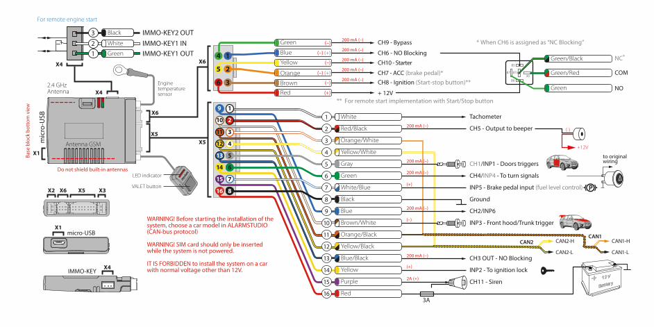
WIRING DESCRIPTION
Х 5 socket (main socket):
• Wire «1» (White) (Tachometer input) — analog input of the tachometer signal, it connects to the tachometer wire or to the signal wire of a nozzle, which provide stable pulses of any polarity cor-responding to the RPM.
• Wire«2» (Red-black) (CH5) — Factory setting is ‘Beeper’. A negative output of additional chan-nel with maximum load current 200mA. This output is multipurpose, it can operate in accordance with selected logic.
• Wire«3» (Orange-white) (CAN1-High) — It connects to appropriate CAN-High wire of the car.
• Wire«4» (Yellow-white) (CAN2-High) — It connects to appropriate CAN2-High wire of the car.
• Wire«5» (Gray) (СН1/INP1) — Factory setting is ‘Door trigger. This wire connects to a wire that becomes grounded when the door opens. This wire is multipurpose, it can operate as input and as output in accordance with selected logic.
• Wire«6» (Green) (СН4/INP4) — Factory setting is ‘Control turn indicators’. This wire connects to the hazard flashers button. A negative output of additional channel with maximum load current 200mA. This wire is multipurpose, it can operate as input and as output in accordance with selected logic.
• Wire«7» (White-Blue) (INP5) — Factory setting is ‘Brake pedal’. This wire connects to the brake pedal trigger where 12V voltage appears when the pedal is pressed (stop lights wire). Brake pedal signal is one of the system’s security zones. This input is multipurpose, it can operate in accordance with selected logic.
• Wire«8» (Black) (Ground) — It should be connected to the car body in a grounding spot. This wire should be connected FIRST during installation.
• Wire«9» (Blue) (CH2/INP6) — Factory setting is free output. A negative output of additional
channel with maximum load current 200mA. This wire is multipurpose, it can operate as input and as output in accordance with selected logic.
• Wire«10» (Brown-White) (INP3) — Factory setting is ‘Front hood and trunk trigger’. This wire connects to appropriate wire that becomes grounded when the front hood opens. This input is multi-purpose, it can operate in accordance with selected logic.
• Wire«11» (Orange-black) (CAN1-Low) — It connects to appropriate CAN-Low wire of the car.
• Wire«12» (Yellow-black) (CAN2-Low) — It connects to appropriate CAN2-Low wire of the car.
• Wire«13» (Blue-Black) (CH3) —Factory setting is ‘Blocking N.O.’. This output is used to control blocking relay with a normally open logic (it becomes grounded when switching on the ignition and security system is not armed). A negative output of additional channel with maximum load current 200mA. This output is multipurpose, it can operate in accordance with selected logic.
• Wire«14» (Yellow) (INP2) — Factory setting is ‘Ignition’. This wire connects to ignition switch or to appropriate wire where 12V voltage appears when ignition is switched on. This input is multipurpose, it can operate in accordance with selected logic.
• Wire«15» (Purple) (Siren) — It connects to siren control wire (+) (maximum load current is 2A).
• Wire«16» (Red) (Power Supply +12V) — It should be connected to reliable conductor with con-stant voltage of 12V.
Х 6 Socket (Relay module):
• Wire«1» (Blue) (CH6) — Factory setting is ‘Blocking N.O.’. This output is used to control blocking relay with a normally open logic (it becomes grounded when switching on the ignition and security system is not armed). A negative output of additional channel with maximum load current 200mA. This output is multipurpose, it can operate in accordance with selected logic
• Wire«2» (Orange) (CH7) — Factory setting is ‘ACC’. The channel is used to control accessories. If
‘Car with START/STOP button’ setting is enabled, the channel will control brake pedal during remote or automatic engine start. A negative output of additional channel with maximum load current 200mA. This output is multipurpose, it can operate in accordance with selected logic.
• Wire«3» (Brown) (CH8) — Factory setting is ‘Ignition’. This output is used to switch on ignition. It allows implementing automatic engine start, turbo timer, ignition support and connecting to igni-tion in series (incut). If ‘Car with START/STOP button’ setting is enabled, the channel will operate in im-pulse mode to control the button. A negative output of additional channel with maximum load current 200mA. This output is multipurpose, it can operate in accordance with selected logic.
• Wire«4» (Green) (CH9)— Factory setting is ‘Bypass’. Output activates during remote or automatic

2928 USER MANUALPANDORA DXL 1840L CAR SERVICE-SECURITY SYSTEM
engine start. A negative output of additional channel with maximum load current 200mA. This output is multipurpose, it can operate in accordance with selected logic.
• Wire«5» (Yellow) (CH10) — Factory setting is ‘Starter’. This output is used to switch on starter of the car. A negative output of additional channel with maximum load capacity 200mA. This output is multipurpose, it can operate in accordance with selected logic.
• Wire«6» (Red) — relay module power supply 12V.
Х 4 Socket (Multifunctional channels)
Use this socket when implementing bypass of original immobilizer using IMMO-KEY1 and IMMO-KEY2 multifunctional channels. Make connections in accordance with installation scheme. The settings of the socket are available in AlarmStudio. Disconnect the system from power supply after changing the settings.
Programming the system
Entering programming menu
To change the system settings or program the system using a computer or VALET button, the sys-tem should be in programming mode. Enter programming mode by entering ‘Service PIN-code’ (fac-tory preset is 1-1-1-1). PIN-code should be entered using external or located on the base unit VALET button. The input is indicated by flashes of external or located on the base unit LED indicator. You can enter the code only if the base unit is powered form USB socket or from external power supply, the igni-tion is switched off, the system is disarmed and maintenance mode is switched off.
If there is no ‘Service PIN-code’, you can enter programming mode using the ‘Secret PIN-code’ written on the owner’s card.
Entering PIN-code:• Enter the first digit of the code using VALET button. Press the button a number of times, equals to
the first digit. Pauses between presses should not exceed 1 second. Each pressing will be confirmed with an orange LED indicator flash. A pause for more than 1 second and a red LED indicator flash confirm the input of the first digit. Then you can enter the next digit.
• Enter the second digit of the code using VALET button. Press the button a number of times, equals to the second digit. Pauses between presses should not exceed 1 second. Each pressing will be confirmed with an orange LED indicator flash. A Pause for more than 1 second and a red LED indicator flash confirm the input of the second digit. Then you can enter the next digit.
• Enter the third digit of the code using VALET button. Press the button a number of times, equals to the third digit. Pauses between presses should not exceed 1 second. Each pressing will be confirmed with an orange LED indicator flash. A Pause for more than 1 second and a red LED indicator flash confirm the input of the third digit. Then you can enter the next digit.
• Enter the fourth digit of the code using VALET button. Press the button a number of times, equals to the fourth digit. Pauses between presses should not exceed 1 second. Each pressing will be confirmed with an orange LED indicator flash. The system will confirm correct PIN-code with the series of red and green flashes and the system will enter programming mode. If the input was incorrect, it will be indicated with a red LED indicator flash and the system will stay in a previous state. New input can be attempted after 5 seconds.
Exit programming mode:To exit programming mode turn on the ignition or turn off power of the base unit. The system will reboot
programmatically (all changes will be saved) after exiting programming mode using ignition. All ways to exit the programming menu are accompanied by sound signals of the siren/Beeper and light signals of the LED indicator. Light signals indicate the number of recorded devices: first green flashes indicate the number of recorded radio tags, red flash indicates registered mobile device
Status indicator lights during PIN-code entering:
Short orange flash Confirmation of VALET button pressingShort red flash Confirmation of entering a PIN-code digitRed and green flashes PIN-code is correctLong red flash PIN-code is incorrect
Preparing to program the system using a computer
The system allows programming all settings and updating software of the base unit via micro-USB ca-ble. If the base unit has not been installed in the vehicle yet, it will be powered via micro-USB cable while programming. To program using a computer, you need a standard USB cable, a computer with Windows XP/Vista/7/8/10 and Pandora AlarmStudio application (you can download it from pandorainfo.com).
It is required to create an account in AlarmStudio to use Pandora CLONE for remote engine start (you can register without a connection to a system). Pandora CLONE procedure requires Internet connection.
In preparation to the programming these stages should be followed:• connect the system and PC via USB cable;• start Pandora Alarm Studio;• enter the programming settings mode by entering the service PIN-code.
3130 USER MANUALPANDORA DXL 1840L CAR SERVICE-SECURITY SYSTEM
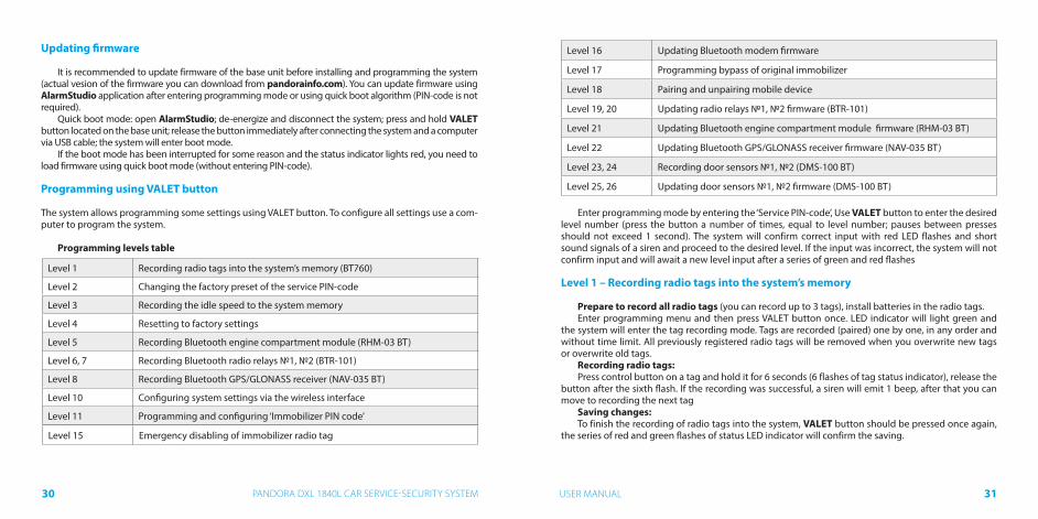
Updating firmware
It is recommended to update firmware of the base unit before installing and programming the system (actual vesion of the firmware you can download from pandorainfo.com). You can update firmware using AlarmStudio application after entering programming mode or using quick boot algorithm (PIN-code is not required).
Quick boot mode: open AlarmStudio; de-energize and disconnect the system; press and hold VALET button located on the base unit; release the button immediately after connecting the system and a computer via USB cable; the system will enter boot mode.
If the boot mode has been interrupted for some reason and the status indicator lights red, you need to load firmware using quick boot mode (without entering PIN-code).
Programming using VALET button
The system allows programming some settings using VALET button. To configure all settings use a com-puter to program the system.
Programming levels table
Level 1 Recording radio tags into the system’s memory (BT760)
Level 2 Changing the factory preset of the service PIN-code
Level 3 Recording the idle speed to the system memory
Level 4 Resetting to factory settings
Level 5 Recording Bluetooth engine compartment module (RHM-03 BT)
Level 6, 7 Recording Bluetooth radio relays №1, №2 (BTR-101)
Level 8 Recording Bluetooth GPS/GLONASS receiver (NAV-035 BT)
Level 10 Configuring system settings via the wireless interface
Level 11 Programming and configuring ‘Immobilizer PIN code’
Level 15 Emergency disabling of immobilizer radio tag
Level 16 Updating Bluetooth modem firmware
Level 17 Programming bypass of original immobilizer
Level 18 Pairing and unpairing mobile device
Level 19, 20 Updating radio relays №1, №2 firmware (BTR-101)
Level 21 Updating Bluetooth engine compartment module firmware (RHM-03 BT)
Level 22 Updating Bluetooth GPS/GLONASS receiver firmware (NAV-035 BT)
Level 23, 24 Recording door sensors №1, №2 (DMS-100 BT)
Level 25, 26 Updating door sensors №1, №2 firmware (DMS-100 BT)
Enter programming mode by entering the ‘Service PIN-code’, Use VALET button to enter the desired level number (press the button a number of times, equal to level number; pauses between presses should not exceed 1 second). The system will confirm correct input with red LED flashes and short sound signals of a siren and proceed to the desired level. If the input was incorrect, the system will not confirm input and will await a new level input after a series of green and red flashes
Level 1 – Recording radio tags into the system’s memory
Prepare to record all radio tags (you can record up to 3 tags), install batteries in the radio tags.Enter programming menu and then press VALET button once. LED indicator will light green and
the system will enter the tag recording mode. Tags are recorded (paired) one by one, in any order and without time limit. All previously registered radio tags will be removed when you overwrite new tags or overwrite old tags.
Recording radio tags:Press control button on a tag and hold it for 6 seconds (6 flashes of tag status indicator), release the
button after the sixth flash. If the recording was successful, a siren will emit 1 beep, after that you can move to recording the next tag
Saving changes:To finish the recording of radio tags into the system, VALET button should be pressed once again,
the series of red and green flashes of status LED indicator will confirm the saving.

3332 USER MANUALPANDORA DXL 1840L CAR SERVICE-SECURITY SYSTEM
Level 2 – Changing the factory preset of the service PIN-code
Prepare a new value of the ‘Service PIN-code’, it should consist of 4 digits (from 1 to 9). Write down or remember the new PIN-code.Enter programming menu and then press VALET button twice. The system will enter ‘Changing Ser-
vice PIN-code’ mode and the status LED indicator will turn off.
Changing the ‘Service PIN-code’:• Enter the first digit of the code using VALET button. Press the button a number of times, equals
to the first digit. Pauses between presses should not exceed 1 second, every pressing will confirm with orange LED indicator flash. Pause for more than 1 second and red LED indicator confirms the input of the first digit. Then you can enter the next digit.
• Enter the other numbers in the same manner. The input of the fourth number will be confirmed by series of red and green LED indicator flashes. The system will wait for PIN-code re-entering.
• Enter all four digits again;• If you were able to correctly enter the ‘Service PIN-code’ twice, the indicator will produce the series
of red and green flashes, new PIN-code will be recorded, the system will return to programming mode. In case of the incorrect code input the indicator will be lit red, the system will return to programming mode.
Level 3 – Recording the idle speed to the system memory
To timely turn off the starter during automatic or remote engine start via digital or analog tachometer input and the correct operation of the ‘Smart Turbo Timer’, it is necessary to record the engine idle speedTo record idle speed to the non-volatile system memory, enter the programming menu. Press VALET button three times. Switch on the ignition and start the engine after entering this level of programming (the engine should be warmed-up, idle speed should match the stable idle speed of the warmed-up en-gine). The system will confirm the presence of the idle speed status with green flashes of LED indicator. Wait until the stable idle speed will be reached and save the changes
Saving changes:Press VALET button once to save idle speed. Successful recording of the idle speed will be confirmed
with the series of red and green flashes of LED indicator. The system will exit programming menu and reboot after saving the idle speed.
Level 4 – Resetting to factory settings.
The procedure recovers the factory settings of the system without deleting previously registered de-vices (tags, mobile device, relays, etc.) that is stored in the non-volatile memory.To reset the settings enter the programming mode and press VALET button four times. Press and hold VALET button for more than 4 seconds until siren sound, then release the button. The system will con-firm the resetting to the factory settings with a long red flash of LED indicator. After that the system will return to a programming mode
Level 5 – Recording Bluetooth engine compartment module
To record a Bluetooth engine compartment module, enter programming mode and press VALET button 5 times. The LED indicator will light green and the system will enter the recording of an engine com-partment module mode. Connect the module in accordance with installation manual. The system will confirm the registration with a short sound signal.
Saving changes:To finish the recording of the engine compartment module, VALET button should be pressed once again, the series of red and green flashes of the status LED will confirm the saving, switch on the ignition to automatically save the settings and exit programming mode.
Levels 6, 7 – Recording Bluetooth radio relays
Radio relays recording is performed one by one starting from the 6 level: radio relay №1 is recorded on the 6 level; radio relay №2 is recorded on the 7 level. The radio relay can be overwrit-ten only on the level of its initial registration.
To record Bluetooth radio relays №1, №2, enter programming mode and press VALET button 6 times for radio relay №1 or 7 times for radio relay №2. LED indicator will light green and the system will enter the recording of a radio relay mode. Connect a relay in accordance with installation manual. The system will confirm recording with a short sound signal.
Saving changes:To finish the recording of the Bluetooth radio relay, VALET button should be pressed once again, the
series of red and green flashes of the status LED indicator will confirm the saving, switch on the ignition to automatically save the settings and exit the programming mode.

3534 USER MANUALPANDORA DXL 1840L CAR SERVICE-SECURITY SYSTEM
Level 8 – Recording Bluetooth GPS/GLONASS receiver (NAV-035 BT)
To record a Bluetooth GPS/GLONASS receiver, enter programming mode and press VALET button 8 times. The LED indicator will light green and the system will enter the recording of a receiver. Connect the receiver in accordance with its installation manual. The system will confirm the registration with a short sound signal and red light of LED indicator.
Saving changes:To finish the recording of the engine compartment module, press VALET button once, the series of
red and green flashes of the status LED will confirm the saving, switch on the ignition to save the set-tings and exit programming mode.
Level 10 – Configuring system settings via the wireless interface
This function is under construction.
Level 11 – Programming and configuring ‘Immobilizer PIN code’
To program the «Immobilizer PIN code», enter the programming mode and press VALET button 11 times. The level is divided into 3 sublevels (Sublevel 11.1 – Selecting buttons; sublevel 11.2 entering PIN-code; sublevel 11.3 – confirmation of the PIN-code input).The system will automatically enter the sublevel 11.1 (Selecting buttons) after entering the level 11. The system can determine buttons via analog “Code immobilizer” input or via digital protocol of a car.
It is necessary to configure an analog input (INP) as ‘Code immobilizer’ in the settings of the base unit inputs when implementing the “Code immobilizer” via an analog input. It may be necessary to switch on the ignition after entering the level 11 of programming (if the car bus is active only when the ignition is switched on) when implementing the “Code immobilizer” via digital car bus protocol.
After selecting active buttons enter the sublevel 11.2 (Entering PIN-code) by pressing VALET but-ton once. Program PIN-code using selected buttons at this sublevel; press VALET button once and enter PIN-code again. To confirm PIN-code re-entering and save all the settings press VALET button once again.
Sublevel 11.1 - Selecting buttons:This sublevel is used to select active buttons via digital protocol of a car or via ‘Code Immobilizer’
analog input. To determine the activity of the analog “Code Immobilizer” input, apply potential to the corresponding input (INP) of the base unit, LED indicator will be flashing orange.
If you determine buttons via digital protocol select one or more buttons (up to four) for entering the secret code of the immobilizer. To do this press the selected button, LED indicator will confirm input
with orange flashes. If there are no orange flashes when any button is pressed, then this button is not recognized by the system, select a different button. Repeat the procedure to select the second, third, fourth button and enter the next sublevel. To enter the next sublevel 11.2l press VALET button once.
Sublevel 11.2 - Entering PIN-code:Program immobilizer deactivation PIN-code using selected button or buttons. Enter the first digit
by pressing the previously selected button (pauses between presses should not exceed 1 second). The base unit will confirm entering with red flash of LED indicator. Enter the second (third, fourth) digit by pressing the previously selected button. The base unit will confirm entering of each digit with red flash of LED indicator.
Input the required number of digits (up to 4) and then press VALET button. The system will confirm receiving of the secret validator code with long red flash of LED indicator and will wait for confirmation of PIN-code.
Sublevel 11.3 - Confirmation of the PIN-code input:11.2 Enter PIN-code again similarly to the procedure (level 11.2 – Entering PIN-code) and press
VALET button. The system will confirm correct PIN-code with red and green flashes of LED indicator and will memorize PIN-code, and then the system will proceed to programming mode awaiting level input. Incorrect confirmation is indicated with long red flash of LED indicator, after that the system will return to programming mode.
Level 15 – Disabling/enabling immobilizer tag
To disabling/enabling of immobilizer tag, enter programming menu and press VALET button 15 times. LED indicator will light green (green light indicates enabled tag) and the system will wait for the “Secret PIN-code” entering. Red light of LED indicates disabled immobilizer tag.
Disabling radio tag:LED indicator will light green after entering the programming level. The system will wait for entering
the ‘Secret PIN-code’. Enter the ‘Secret PIN-code’ that is written on the owner’s plastic card. The system will confirm disabling of the radio tag with two sound signals of the siren and a long red LED flash. After that the system will return to the programming menu. If the PIN-code is not entered within 10 seconds or the input is incorrect, a siren will sound one signal, LED will produce the series of red and green flashes and the system will return to the programming menu.
Enabling radio tag:LED indicator will light red after entering the programming level. The system will wait for action.
Press VALET button once to enable radio tag. The system will confirm enabling with one short sound signal of a siren and a green LED light. After that the system will return to the programming menu.
3736 USER MANUALPANDORA DXL 1840L CAR SERVICE-SECURITY SYSTEM
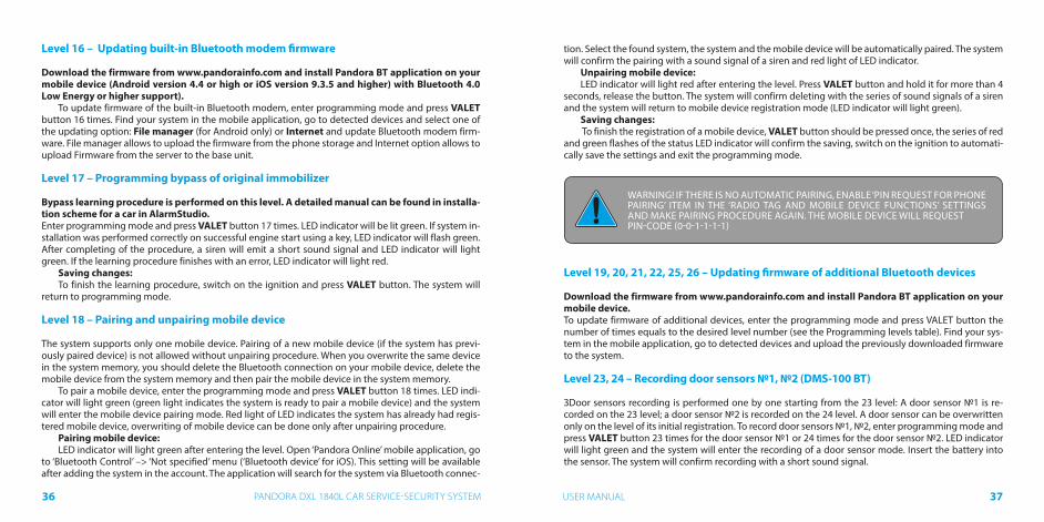
Level 16 – Updating built-in Bluetooth modem firmware
Download the firmware from www.pandorainfo.com and install Pandora BT application on your mobile device (Android version 4.4 or high or iOS version 9.3.5 and higher) with Bluetooth 4.0 Low Energy or higher support).
To update firmware of the built-in Bluetooth modem, enter programming mode and press VALET button 16 times. Find your system in the mobile application, go to detected devices and select one of the updating option: File manager (for Android only) or Internet and update Bluetooth modem firm-ware. File manager allows to upload the firmware from the phone storage and Internet option allows to upload Firmware from the server to the base unit.
Level 17 – Programming bypass of original immobilizer
Bypass learning procedure is performed on this level. A detailed manual can be found in installa-tion scheme for a car in AlarmStudio.Enter programming mode and press VALET button 17 times. LED indicator will be lit green. If system in-stallation was performed correctly on successful engine start using a key, LED indicator will flash green. After completing of the procedure, a siren will emit a short sound signal and LED indicator will light green. If the learning procedure finishes with an error, LED indicator will light red.
Saving changes:To finish the learning procedure, switch on the ignition and press VALET button. The system will
return to programming mode.
Level 18 – Pairing and unpairing mobile device
The system supports only one mobile device. Pairing of a new mobile device (if the system has previ-ously paired device) is not allowed without unpairing procedure. When you overwrite the same device in the system memory, you should delete the Bluetooth connection on your mobile device, delete the mobile device from the system memory and then pair the mobile device in the system memory.
To pair a mobile device, enter the programming mode and press VALET button 18 times. LED indi-cator will light green (green light indicates the system is ready to pair a mobile device) and the system will enter the mobile device pairing mode. Red light of LED indicates the system has already had regis-tered mobile device, overwriting of mobile device can be done only after unpairing procedure.
Pairing mobile device:LED indicator will light green after entering the level. Open ‘Pandora Online’ mobile application, go
to ‘Bluetooth Control’ –> ‘Not specified’ menu (‘Bluetooth device’ for iOS). This setting will be available after adding the system in the account. The application will search for the system via Bluetooth connec-
tion. Select the found system, the system and the mobile device will be automatically paired. The system will confirm the pairing with a sound signal of a siren and red light of LED indicator.
Unpairing mobile device:LED indicator will light red after entering the level. Press VALET button and hold it for more than 4
seconds, release the button. The system will confirm deleting with the series of sound signals of a siren and the system will return to mobile device registration mode (LED indicator will light green).
Saving changes: To finish the registration of a mobile device, VALET button should be pressed once, the series of red
and green flashes of the status LED indicator will confirm the saving, switch on the ignition to automati-cally save the settings and exit the programming mode.
WARNING! IF THERE IS NO AUTOMATIC PAIRING, ENABLE ‘PIN REQUEST FOR PHONE PAIRING’ ITEM IN THE ‘RADIO TAG AND MOBILE DEVICE FUNCTIONS’ SETTINGS AND MAKE PAIRING PROCEDURE AGAIN. THE MOBILE DEVICE WILL REQUEST PIN-CODE (0-0-1-1-1-1)
Level 19, 20, 21, 22, 25, 26 – Updating firmware of additional Bluetooth devices
Download the firmware from www.pandorainfo.com and install Pandora BT application on your mobile device.To update firmware of additional devices, enter the programming mode and press VALET button the number of times equals to the desired level number (see the Programming levels table). Find your sys-tem in the mobile application, go to detected devices and upload the previously downloaded firmware to the system.
Level 23, 24 – Recording door sensors №1, №2 (DMS-100 BT)
ЗDoor sensors recording is performed one by one starting from the 23 level: A door sensor №1 is re-corded on the 23 level; a door sensor №2 is recorded on the 24 level. A door sensor can be overwritten only on the level of its initial registration. To record door sensors №1, №2, enter programming mode and press VALET button 23 times for the door sensor №1 or 24 times for the door sensor №2. LED indicator will light green and the system will enter the recording of a door sensor mode. Insert the battery into the sensor. The system will confirm recording with a short sound signal.

3938 USER MANUALPANDORA DXL 1840L CAR SERVICE-SECURITY SYSTEM
Saving changes:To finish the recording of the Bluetooth radio relay, press VALET button once, the series of red and green flashes of the status LED indicator will confirm the saving, switch on the ignition to save the settings and exit the programming mode.
Additional device
Blocking radio relay BTR-101Blocking BTR-101 radio relay is optionally available for Bluetooth systems. Blocking radio relay with
built-in accelerometer should be placed in the engine compartment. Herewith zone of built-in aerial 2,4 GHz should not be shielded. Provide a rigid fastening to the car body or to the fixed wirings. It is forbidden to hide the module in wiring. To save energy, radio relay power is connected to the ignition. Radio relay is normally closed and has a full set of contacts. Blocking is carried out on unauthorized movement.
2
5
1
4
3
NO
NC
COM
programming
6
Antenna 2,4 GHz
+12V
WARINGI! DO NOT PLACE RADIO RELAYS DIRECTLY ON THE ENGINE!Radio tag BT-760
Radio module of engine compartment RHM-03 BT
Radio module of engine compartment RHM-03 BTThis module is designed to simplify the system installation and
wiring in the engine compartment module. Data transmission and control are performed via system standard 2.4 GHz radio channel with Bluetooth 4.2 Low Energy protocol. The module allows to control front hood locks, siren and digital engine preheater it also allows to block the engine (engine blocking can be activated im-mediately or when determining motion with built-in accelerometer, it depends on the system configuration). The module also sends in-formation about the temperature to the base unit.
GPS/GLONASS -receiver NAV-035 BTPandora NAV-035 BT is a high-sensitivity GPS/GLONASS receiver
that designed to be used with Pandora service-security systems. The receiver operates on 2,4 GHz wireless interface. The receiver can be placed under the dashboard, aerial should be placed in the top for better reception of the satellite signal
Control devicesGPS/GLONASS-receiver NAV-035BT

4140 USER MANUALPANDORA DXL 1840L CAR SERVICE-SECURITY SYSTEM
Siren sounds and turn light signals
Signal name Signal description
Alarm mode, PANIC mode Incessant sound and light signals for 30 sec
Arming 1 sound and 1 light signals
Disarming 2 sound and 2 light signals
‘Sensors triggered’ signal when disarming 4 sound and 4 light signals
‘Sensor malfunction’ signal when arming 4 sound and 4 light signals
Sensor warning level triggered 3 sound signals
Car search 5 sound and 5 light signals
Beeper sound signals
Signal name Signal description
Enable the maintenance mode 1 sound signal
Disable the maintenance mode 2 sound signals
A battery in the radio tag is discharged 3 sound signals / 3 times
Absence of the radio tag 5 sound signals / 5 times
Blocking warning Fast sound singals
Meaning of indicator LED colors
Indicator status Meaning
Short red flashes The system is armed
Lit red The system is preparing for automatic arming
Orange flash Confirms VALET button press
Green flashes Confirms a number of recorded remotes (when switching on ignition)
Red flash Confirms a recorded mobile device (when switching on ignition)
Red and green flashes PIN-code confirmed
Faded The system is disarmed
Checking the number of registered radio tags/mobile devices
The number of recorded tags and mobile device can be checked by the number of green and red flashes of LED indicator. Number of registered tags can be checked every time the ignition is switched on when the system is disarmed. Number of green LED flashes will indicate the number of recorded tags, following red flash will indicate registered mobile device.
You can also check the number of recorded tags and registered mobile device by taking off and put-ting back on battery terminal. The system will emit short sound signals from a siren with less than 1 sec. interval. The number of the signals equals to the number of recorded tags. After a pause of 2 seconds the system signal will indicate registered mobile device.
4342 USER MANUALPANDORA DXL 1840L CAR SERVICE-SECURITY SYSTEM
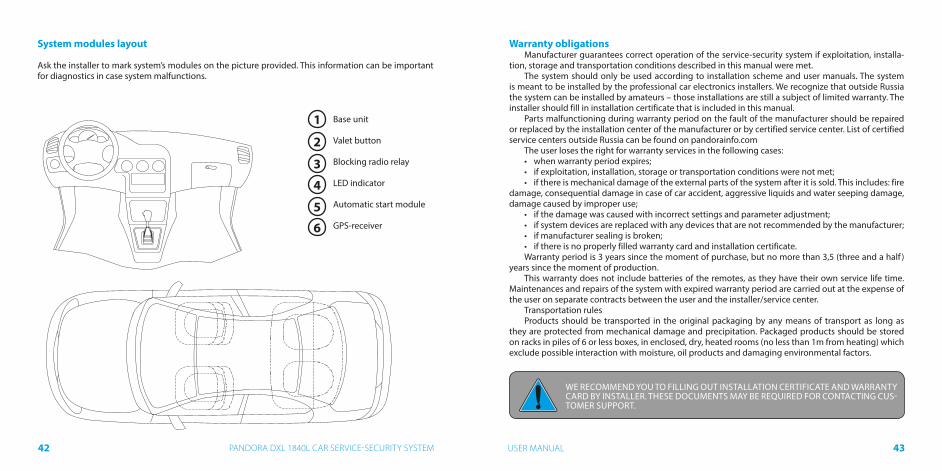
System modules layout
Ask the installer to mark system’s modules on the picture provided. This information can be important for diagnostics in case system malfunctions.
Base unit
Valet button
Blocking radio relay
LED indicator
Automatic start module
GPS-receiver
1
2
3
4
5
6
Warranty obligationsManufacturer guarantees correct operation of the service-security system if exploitation, installa-
tion, storage and transportation conditions described in this manual were met.The system should only be used according to installation scheme and user manuals. The system
is meant to be installed by the professional car electronics installers. We recognize that outside Russia the system can be installed by amateurs – those installations are still a subject of limited warranty. The installer should fill in installation certificate that is included in this manual.
Parts malfunctioning during warranty period on the fault of the manufacturer should be repaired or replaced by the installation center of the manufacturer or by certified service center. List of certified service centers outside Russia can be found on pandorainfo.com
The user loses the right for warranty services in the following cases:• when warranty period expires;• if exploitation, installation, storage or transportation conditions were not met;• if there is mechanical damage of the external parts of the system after it is sold. This includes: fire
damage, consequential damage in case of car accident, aggressive liquids and water seeping damage, damage caused by improper use;
• if the damage was caused with incorrect settings and parameter adjustment;• if system devices are replaced with any devices that are not recommended by the manufacturer;• if manufacturer sealing is broken;• if there is no properly filled warranty card and installation certificate.Warranty period is 3 years since the moment of purchase, but no more than 3,5 (three and a half )
years since the moment of production.This warranty does not include batteries of the remotes, as they have their own service life time.
Maintenances and repairs of the system with expired warranty period are carried out at the expense of the user on separate contracts between the user and the installer/service center.
Transportation rulesProducts should be transported in the original packaging by any means of transport as long as
they are protected from mechanical damage and precipitation. Packaged products should be stored on racks in piles of 6 or less boxes, in enclosed, dry, heated rooms (no less than 1m from heating) which exclude possible interaction with moisture, oil products and damaging environmental factors.
WE RECOMMEND YOU TO FILLING OUT INSTALLATION CERTIFICATE AND WARRANTY CARD BY INSTALLER. THESE DOCUMENTS MAY BE REQUIRED FOR CONTACTING CUS-TOMER SUPPORT.

4544 USER MANUALPANDORA DXL 1840L CAR SERVICE-SECURITY SYSTEM
INSTALLATION CERTIFCATE
I, the undersigned_________________________________________________________ Position, name. ______________________________________________________________________________professional installer, certify that installation of the service-security system, specified below, was carried out by me in accordance with manuals and schemes provided by the manufacturer.
Car specifications:
Car model____________________________________________ Type _____________________
Id number (VIN)_________________________________________________________________
Registration number_____________________________________________________________
Security system specification:
Model Pandora DXL 1840L
Serial number______________________________
Service center name, full address and installer’s stamp____________________________________________________________________________________________________________________________________________________________
Signature_____________________/___________________________________/ SignatorWork accepted__________________/___________________________________/ SignatorDate «____»___________________20___year.
ACCEPTANCE CERTIFICATE
Model Pandora DXL 1840L is in conformity with Electromagnetic Compatibility Directive EMC 2004/108/EC and R&TTE Directive 1999/5/EC.
Serial number ______________________________ Date of production___________________
Responsible person’s signature (stamp)
Packager______________________________________________________________________
Signature (personal stamp)
WARRANTY CARD
Model Pandora DXL 1840L
Serial number _________________________________________________________________
Date of purchase «____» ______________________ 20____year
______________________________________________________________________________Seller’s (installer’s) stamp
Seller’s signature _______________________________________________________________

4746 USER MANUALPANDORA DXL 1840L CAR SERVICE-SECURITY SYSTEM

48 PANDORA DXL 1840L CAR SERVICE-SECURITY SYSTEM