Embed Size (px)
Citation preview
Package Design Guide
This guide has been prepared to assist packaging designers in the selection and
utilization of ETHAFOAM brand polyethylene foam and other Performance Foams
products for protective packaging applications. It contains recommended
considerations and procedures for the design and development of highly protective
and cost-efficient packaging.
This information is offered to facilitate the process of designing and developing
packing that provides the desired level of protection at the most reasonable cost.
It is recommended that, once a package design has been determined, a prototype
product-package combination should be developed and tested for performance
prior to final inspection.
Preliminary Design Considerations
The first step in designing a protective packaging solution is the selection of a
cushioning material that is appropriate for the application.
As a general rule, ETHAFOAM polyethylene foams are best suited to protect
products which can be described as relatively high in value and moderately fragile.
Keeping damage rates for products of this nature to a minimum requires a strong,
resilient cushioning material that reliably protects against multiple impacts. In
other words, care must be taken to select a cushioning material that is not
damaged by initial impacts and recovers to maintain its cushioning protection
against repeated shocks.
ETHAFOAM products are resilient in nature, giving them outstanding recovery
characteristics that provide outstanding cushioning protection against repeated
impacts. And ETHAFOAM products are available in a variety of strengths, making
them suitable for protecting products ranging from just a few pounds up to
hundreds of pounds in weight.
STEP ONE: Determine Product Fragility
The first step toward determining the amount of cushioning a product requires is
to determine the amount of mechanical shock the product can survive on its own.
There are several common terms for this, with "fragility" and "g-factor" being the
most common.
Fragility is normally expressed in units of "g’s" and indicates the maximum
deceleration the product can withstand without being damaged. The more fragile
a product is, the lower its g-factor. The table below helps to illustrate this
concept.

Approximate Fragility of Typical Packaged Articles
Class Typical Contents Fragility
Extremely Fragile Missile guidance systems, precision aligned
test instruments
15-25 g’s
Very Delicate Mechanically shock-mounted instruments
and electronic equipment (Shock mounts
should be firmly secure prior to packaging.
They are provided for in-service protection
only.)
25-40 g’s
Delicate Aircraft accessories, electric typewriters,
cash registers and other electronically
operated office equipment
40-60 g’s
Moderately Delicate Television receivers, aircraft accessories 60-85 g’s
Moderately Rugged Laundry equipment, refirgerators,
appliances
85-115 g’s
Rugged Machinery 115 g’s and up
Ideally, the fragility of a product is determined by subjecting it to a series of
gradually more severe shocks (decelerations) in order to find the lowest severity
impact that will damage the product. The highest deceleration, which did not
cause damage, is then known to be the product’s g-factor.
It may be necessary to determine fragility levels for a product in various
orientations, as it is not uncommon for a product to exhibit greater strength in one
direction than another. Even very similar models should be tested individually as
it’s seldom that fragility for one model may be safely assumed from another.
There is no substitute for fragility test data. Educated guesses as to a product’s
fragility are often counterproductive to the design process. If the g-factor is
estimated too high, and the product is unable to survive as much shock as
anticipated, the packaging will be underdesigned and significant shipping damage
is likely to occur. On the other hand, if the g-factor is estimated too low, and the
product can actually withstand more shock than anticipated, the packaging will be
overdesigned and unnecessarily expensive.
STEP TWO: Determine Conditions the Product Will Encounter
Once product fragility is determined, the packaging designer should next consider
the handling and transportation environment the product will face.

To establish the amount of shock the product may encounter, it is necessary to
determine the height from which the product may be dropped. Drop heights are
generally established by the product’s weight, which usually reflect how the
product will be handled.
The chart below shows typical drop heights for products of various weights, and
may be used if you lack specific information about the handling likely to be
encountered in your product’s particular distribution chain.
Typical Drop Heights
Weight Range (lbs) Type of Handling Drop Height (in)
0-10 1 person throwing 42
10-20 1 person carrying 36
20-50 1 person carrying 30
50-100 2 person carrying 24
100-250 Light equipment 18
250+ Heavy equipment handling 12† †NOTE: Palletized products may receive drops of up to six inches.
STEP THREE: Calculate Fundamental Cushion Requirements
When product fragility (g-factor) and handling environment (drop height) have
been determined, the procedure that follows can be used to determine the
amount of functional cushioning material which will provide adequate protection
for the packaged item.
By functional cushioning material, we mean that portion of the design which
directly supports the load and functions to absorb shock during impacts. There may
be additional material used in the design as well to connect functional cushioning
parts together, facilitate pack assembly, etc. This procedure does not take into
account such factors as the effect of the outer container or other effects that may
take place inside the container.
Generally such effects are beneficial so that this procedure can confidently be
used as a starting point to develop packaging that provides an assured level of
protection and optimum cost-efficiency. To calculate functional cushioning needs
it will be necessary to understand and use dynamic cushioning curves.

Using Dynamic Cushioning
Curves: An Overview
A cushioning curve shows how a
particular packaging material of a
given thickness behaves at different
impact conditions. Curves are
generated by dropping a series of
known weights onto a cushion sample
from a specified height and
measuring the amount of shock
experienced by the weights as they
impact the foam. In simple terms,
this testing represents a product
dropping on a cushion from a height
likely to be encountered during
shipment.
An idealized cushioning curve is shown below. It represents the cushioning
performance of a cushioning material for a given combination of thickness and
drop height. The horizontal axis represents a range of static loadings (in pounds
per square inch) that packaged items might apply to the cushioning material. The
vertical axis represents the shock experienced as the cushion is impacted. Curves
are often presented for both first impact and multiple impact (average of drops 2-
5) data. It is common to include data for several cushion thicknesses from a
constant drop height on a single set of axes.
Cushioning curves for ETHAFOAM* products may be obtained by contacting your
local Dow-authorized fabricator, your local Dow representative, or Dow’s Research
and Development facility.
Typical dynamic cushioning curve

Using Dynamic Cushioning Curves:
An Example
An object to be packaged is a 10-
inch cube weighing 60 pounds with a
fragility of 50 g’s. Since a product
typically faces repeated impacts
during shipment, you will probably
wish to use multiple-impact data.
The typical drop height for a
product of this weight may be
estimated from the chart below as
24 inches, however specific
knowledge of shipping conditions or
corporate standards may dictate a
different choice for drop height.
First, obtain the cushioning curves
for the cushioning material you wish
to use. Locate curves that represent
multiple impact data from a drop height of 24 inches. One such set of curves is
shown here.
Determining Thickness
Using the chart below as a reference, locate our product’s fragility level (50 g’s)
on the vertical axis of the figure, and draw an imaginary horizontal line across the
chart at this level.
This separates the chart into two sections:
our fragility line and lower, where the packaged item will be able to survive the
anticipated shock level, and
the section above our line where the shock levels are high enough to damage the
product
Note that in this example, a 1-inch thickness of this cushioning material will not
protect the item down to 50 g’s because the entire 1-inch curve is located above
the 50 g line, in the "damage" zone. All of the other curves, representing cushions
2 inches thick and greater, have portions down in the "no damage" zone, and thus
can be used. In most cases, shipping and handling considerations provide a strong
cost incentive to design as small a package size as possible, so the thinnest cushion
thickness which will do the job is most often selected. In this case, we will choose
a thickness of 2 inches.
Determining Cushion Thickness
24" drop height, 2-5 drop average

Determining Static Loading
and Bearing Area
Only a portion of the 2-inch cushion
curve can be used to protect our
product to 50 g’s. As seen below,
the useable part of the curve is
bounded by a static loading of 0.3
psi at the low end, and 1.4 psi at
the high end. This tells us that, with
a 2-inch cushion, we can apply a
static loading anywhere within this
"cushioning range" and still protect
to 50 g’s or lower.
We now must choose a static
loading to use within this range and
design our cushions. The highest
static loading value within the
cushioning range will result in the most economical design because it will use less
cushioning material to provide adequate protection, thus lowering design costs.
Continuing with our example will illustrate how.
Once we have selected a static loading, we can calculate how many square inches
of foam in our chosen thickness we’ll need to support and protect any side of the
packaged product. In most cases it will be necessary to design a cushion to protect
each of the faces of the product.
The cushion bearing area is easily calculated as the product weight divided by our
chosen static loading. In this example, we have an allowable static loading range
of 0.3 to 1.4 psi. If we were to choose to design with a static loading at the lower
end of our range, 0.3 psi, we would divide our 60 pound product weight by 0.3 psi
and find that we would need to support our product with 200 square inches of
foam to produce a design which loads the foam to 0.3 psi.
If we were to choose the higher loading value of 1.4 psi instead, we would divide
60 pounds by 1.4 psi and find that only 43 square inches of foam are necessary to
support the product at this higher loading. This is a 78.5% reduction in cushioning
material compared to designing at 0.3 psi. You can imagine the cost savings that
can result.
The use of higher loading values to optimize designs cannot be overemphasized. As
a general rule, if you can double or triple the loading value and still not exceed
your product fragility level, you can reduce your cushion usage by one-half to two-
thirds. As a result, total material costs will be minimized.
Determining Static Loading Range
24" drop height, 2-5 drop average

Note that it may be possible to use even a smaller volume of foam by increasing
thickness somewhat and taking advantage of the higher loading (and smaller
bearing area) this allows. The resulting increase in shipping and handling costs due
to package size increase is often greater than the saving in cushion material costs,
so designing to the minimum thickness is the general practice.
By repeating this procedure with several materials, you can quickly generate
comparisons, which will allow you to strike an economical balance between
material cost and package size.
STEP FOUR: Recognizing Design Constraints
In most cases, the design approach we used in step three, i.e. using the highest
possible static loading, will produce economical designs which adequately protect
your packaged product. There are three constraints that must be checked
however, to be sure this loading will not create other problems: compressive
creep, cushion buckling, and extreme temperature effects.
Consider Compressive Creep
Compressive creep is the gradual loss of thickness a material may experience if
placed under a constant load for an extended period of time. Significant
compressive creep will result in the packaged product loosening in the cushion and
becoming vulnerable to excessive movement inside the package during shipment.
As a general rule, creep of 10% is recognized as a practical upper limit. In some
cases creep losses of over 10% in thickness have been shown to result in a
significant loss of cushion performance.
Should it be found that creep in excess of 10% is anticipated, designers should
recalculate the functional foam requirement using a lower static-loading figure.
Spreading the loading over a larger area will reduce compressive creep.
The recommended loading limits to avoid excessive creep for various ETHAFOAM*
polyethylene foam products are shown in below. Published dynamic cushioning
data on ETHAFOAM cuts cushioning curves off at these limits to prevent you from
inadvertently exceeding them.
These limits are believed to be adequate for temperatures encountered in a
normal shipping environment. If exposure to excessive temperatures above 120°F
are anticipated, lower loadings may be desirable. Consult product data sheets for
compressive creep data on individual products.

Recommended Loading Limits for ETHAFOAM Brand Product
Material Static Loading Limit
ETHAFOAM Nova 1.5 psi
ETHAFOAM Select 2.0 psi
ETHAFOAM 220, 4101, M1 2.5 psi
ETHAFOAM HS-45, M3 5.0 psi
ETHAFOAM HS-600, M4 10.0 psi
ETHAFOAM HS-900, M5 20.0 psi

Consider Cushion Buckling
Buckling Coefficients for ETHAFOAM 220 at
Various Static Loadings
Buckling Coefficients for ETHAFOAM Select at
Various Static Loadings
Buckling Coefficients for ETHAFOAM Nova at
Various Static Loadings

Buckling is the non-uniform compression of a
cushion. When buckling occurs, the energy of the
impact is not transferred evenly throughout the
cushion and more shock is transferred to the
package contents. Buckling usually occurs when
the cushions become too tall and thin.
Buckling is actually less of a problem with ETHAFOAM* products than with many
other cushioning materials. Yet it is one more factor you have to consider when
designing a package. By using the charts and formulas presented below, you’ll be
able to account for buckling in your designs and prevent any potential problems.
The tables help determine when the shape of the cushions can cause non-uniform
compression, or buckling. They provide width-to-thickness coefficients for
different static loading values and enable the designer to check for buckling
potential.
To use the charts, determine the static loading (in psi) your product places on the
cushion (divide product weight by surface area). Next, find the static loading value
on the horizontal axis of the chart and read up to where the curve crosses it to
find the buckling coefficient.
Next, multiply this coefficient by the thickness of the cushion to determine how
wide the cushion must be to resist buckling. The example below will help illustrate
how the chart and formula are used.
In cases where you must increase bearing area to avoid buckling, this results in
decreased static loading. Check to see if this brings you into an appropriate loading
range for the next lower strength grade of ETHAFOAM polyethylene foam, as it may
be possible to redesign into a lower strength material more economically.
Let’s assume you plan to use a 3-inch thick pad of ETHAFOAM 220 to cushion a side
of your product, which presents a static load of 10 psi. You’d refer to Buckling
Coefficients for ETHAFOAM 220 at Various Static Loadings, find 1.0 psi along the
bottom and follow the vertical line straight up until it intersects the plot line.
From this point, follow the horizontal line to the left where you’ll find the W/T
coefficient. In this case, the coefficient is 0.7. Using the formula T x W/T = W, you
can now find the minimum width: 3"x 0.7 = 2.1". Your cushion must be at least 2.1
inches wide or long to resist buckling.
Note: For higher strength, higher density ETHAFOAM products, the use of a 0.75
buckling coefficient is recommended.
†Typical values, not product pecification limits.
Note: for higher strenght, higher density
ETHAFOAM products, the use of a constant
buckling coefficient (W/T) of 0.75 is
recommended.

Consider Extreme Temperature Effects
One of the advantages of ETHAFOAM* polyethylene foams is that they retain their
properties and characteristics with minimal change over a wide range of
temperatures. However, as with all thermoplastic foams, when they are exposed
to extremely high or low temperatures over a considerable length of time, they
may be affected. The materials become stiffer at low temperatures and
increasingly softer at higher temperatures. In extreme cases, it may become
necessary to compensate for these effects in your design. Consult the individual
product data sheets for ETHAFOAM available data on cushioning performance at
extreme temperatures.
STEP FIVE: Design Prototypes and Test
Certainly no specific recommendations can be made about how to fabricate and
position the foam on or around a particular product. Each packaging design must
be developed separately, given the large number of variables involved.
The functional foam determinations made in conjunction with dynamic cushioning
curves of ETHAFOAM* products, does not account for any protective contribution
made by an outer container. It also does not account for effects such as shear and
friction within the container, all of which may enhance the performance of the
design to lower shock levels than those indicated by dynamic cushioning curves.
For this reason, it is highly recommended that you build and test a prototype of
your cushion design to determine its actual performance. In many cases you will
find that its performance exceeds your needs and, based on prototype testing, you
can cut back on the amount of ETHAFOAM in the pack even further for an even
more economical pack design. Any such modified designs should also then be
tested to verify their performance.
Performance testing of prototype packages designed with ETHAFOAM polyethylene
foam products is one of the services available from our research center. For more
information, contact our technical staff at (800) 441-4369, or your local Dow-
authorized fabricator.
STEP SIX: Consider Vibration Effects
For most products, a package that provides protection against mechanical shock
during shipment is all that is required. There are some products, however, which
are known to be susceptible to damage from vibration they might experience
during transportation.
Every mode of transport subjects the packages being shipped to some amount of
vibration at various frequencies. In order to provide products which are prone to
vibration damage with protection against such effects, it is essential to determine
the natural frequency of any component which is prone to vibration damage, and
compare it against the vibration characteristics of your package design.
Every cushioning system has a range of vibrational frequencies in which it amplifies
vibration and passes on a more severe vibration to the packaged product than it
receives from the transport environment. At frequencies lower than the
amplification range, the cushion will pass the vibration on to the packaged product
essentially unchanged. In such cases, the packaged product is said to be directly
coupled to the external container.
At frequencies higher than the amplification range, the cushion will attenuate the
vibration, that is, it will absorb some of the vibration within the cushion and
reduce the severity of the vibration it passes on to the packaged product.
For most vibration-sensitive products, making sure that the package design does
not amplify vibration in the product’s natural frequency is enough to prevent
vibrational damage from occurring during shipment. For severely vibration-
sensitive products, however, it may be necessary for the package design to
actually attenuate the frequencies of concern.
As with shock, there is no substitute for actually testing the vibration
characteristics of your design. However, in some cases, vibration performance may
be estimated from some knowledge of the vibrational characteristics of the
ETHAFOAM* product used.
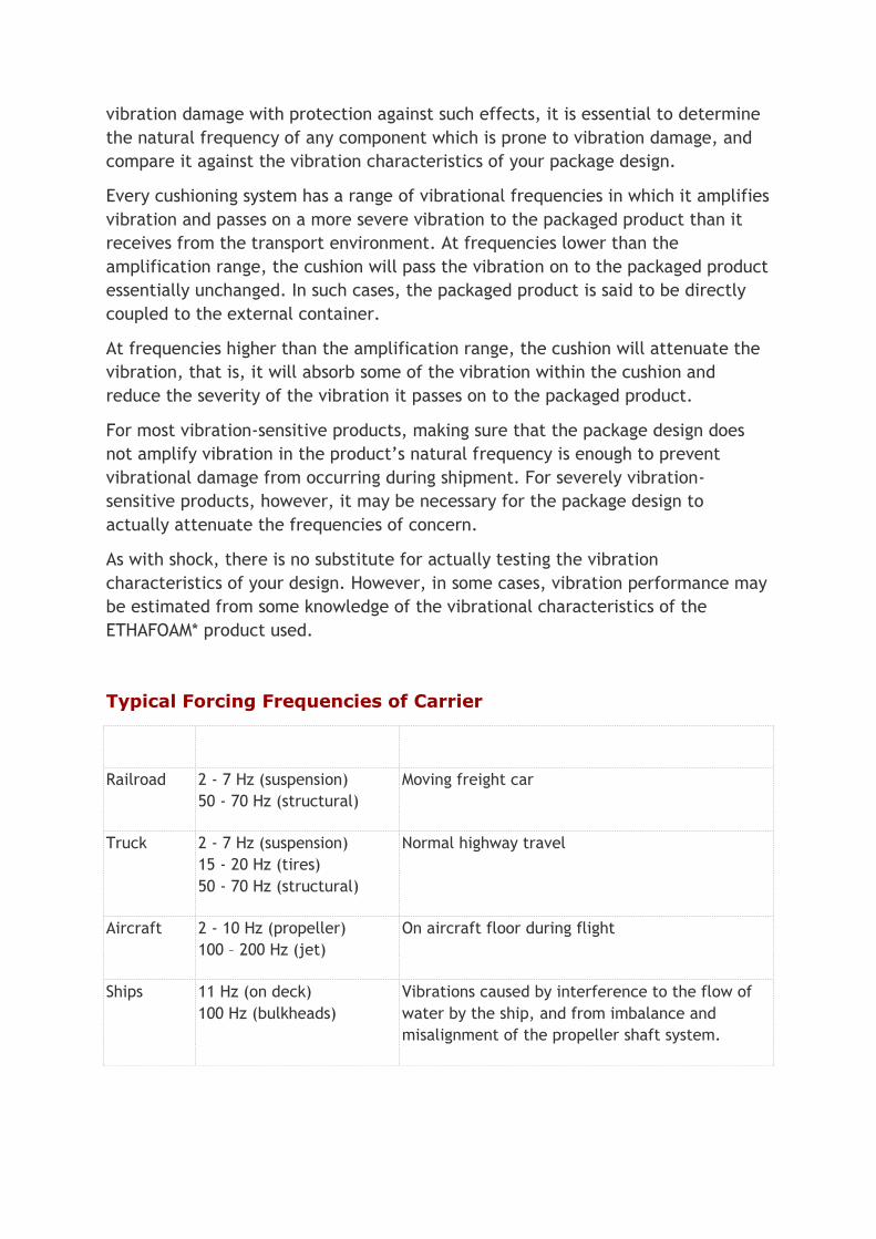
Typical Forcing Frequencies of Carrier
Carrier Frequency Range Conditions
Railroad 2 - 7 Hz (suspension)
50 - 70 Hz (structural)
Moving freight car
Truck 2 - 7 Hz (suspension)
15 - 20 Hz (tires)
50 - 70 Hz (structural)
Normal highway travel
Aircraft 2 - 10 Hz (propeller)
100 – 200 Hz (jet)
On aircraft floor during flight
Ships 11 Hz (on deck)
100 Hz (bulkheads)
Vibrations caused by interference to the flow of
water by the ship, and from imbalance and
misalignment of the propeller shaft system.

Material response is often given in diagrams similar to those below, which
represent performance for a given thickness of material. Note that for any
frequency, one can estimate whether the package will perform in direct coupling,
amplification, or attenuation mode as a function of the static loading applied to
the cushion.
Check the product data sheets for any vibrational response data which may be
available for the individual ETHAFOAM polyethylene foam products.
Vibrational performance testing of prototype packages designed with ETHAFOAM
polyethylene foam products is one of the services available from our research
center. Some size and weight limits apply. For more information, contact our
technical staff at (800) 441-4369, or your local Dow-authorized fabricator.
Typical Vibrational Response of a Package
Vibration Response of a Cushioning Material
STEP SEVEN: Monitor Performance
If it works, question it
There are many assumptions that went into your design development, among them
that the drop height likely to be encountered is realistic, and that the fragility
value used is representative of the product actually being packaged. Even when
you are lucky enough to be working with a fragility value that was obtained by
actual testing, in many cases what was tested was a prototype, and the production
units may be more or less rugged than indicated.
For these reasons, it is a good practice to monitor the performance of your design
in actual use. This will help you to determine if your design is providing more real-
world performance than is actually required, or not enough. It can also allow you
to determine when internal changes in the design of the packaged product might
alter the requirements for package performance.
Just as no shipper can afford high damage rates, neither can he afford to
overpackage. Monitoring of packaging performance on an ongoing basis can also
help determine if further economies can be achieved without sacrificing
protection.
Foam Fabrication
Whether working from our design or a customer supplied drawing, we have the
experience to fabricate even the most complex foam components. Our 65,000
square foot facility houses the most advanced foam fabrication equipment in the
Western United States.
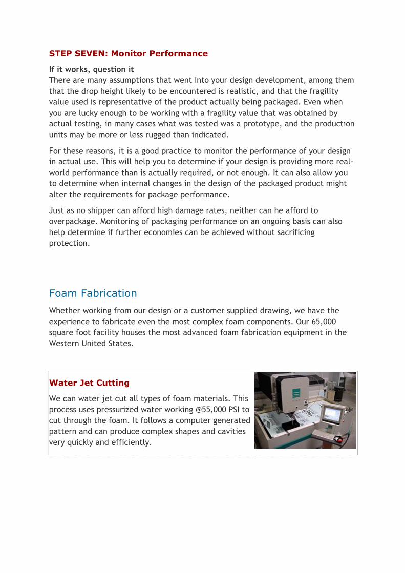
Water Jet Cutting
We can water jet cut all types of foam materials. This
process uses pressurized water working @55,000 PSI to
cut through the foam. It follows a computer generated
pattern and can produce complex shapes and cavities
very quickly and efficiently.

CNC Routing
We can route all polyethylene and closed cell foams
including E.P.S. This process uses a high speed router
that follows AutoCAD drawings to produce complex
foam cavities.
Hot-Wire Cutting
We can hot-wire almost all types of foam. This process
uses custom bent hot wires to produce a wide variety
of complex cavities.
Die Cutting
We can die-cut almost all foams. This process uses
custom shaped steel rules that are stamped through
the foam.
Thermoforming
We can thermoform all types of cross-linked
polyethylene foams. Our thermoforming capabilities
vary from simple tray liners to very complex designs.
Profiling
Our profiler has a 82" X 96" table, and utilizes hot
wires to produce repeated complex shapes throughout
a bun of material. The profiler works with all foams.
Slitting
Our automatic slitter converts large volumes of
material into sheets as thin as 1/16TH of an inch.

We Also have:
Automatic band saws
Convoluter
Laminators
Automatic glue lines
Peelers
Foam Selection Guide
Follow these easy steps:
1. Determine the “fragility” level of your product-using Chart 1 as a guideline.
2. Determine your product's static loading on the foam (psi). Do this by dividing
your products gross weight by the largest surface area that will rest on the
foam (square inches).
Example: If your product weighs 10 lbs. and the largest surface area which will
rest on the foam insert is 25 in.2, the static loading will be 0.4 p.s.i. (10/25 =
.04)
3. Match your answer to Chart 2.
4. Find your foam on Chart 3. Enter at your products fragility level, move
horizontally to intersect the drop height curve. Then move vertically from the
point of intersection to determine the required foam thickness.
Chart 1: Approximate Fragility of Typical Packaged Articles
Class Typical Contents Fragility
Extremely Fragile Missile guidance systems, precision aligned
test instruments
15-25 g’s
Very Delicate Mechanically shock-mounted instruments
and electronic equipment (Shock mounts
should be firmly secure prior to packaging.
They are provided for in-service protection
only.)
25-40 g’s
Delicate Aircraft accessories, electric typewriters,
cash registers and other electronically
operated office equipment
40-60 g’s
Moderately Delicate Television receivers, aircraft accessories 60-85 g’s
Moderately Rugged Laundry equipment, refirgerators,
appliances
85-115 g’s
Rugged Machinery 115 g’s and up

Chart 2: Foam Selection
Static Loading Recommended Foam
0.1 to 3.5 2# polyurethane
3.5 to 6.0 4# polyurethane
0.6 to 1.2 2# polyethylene
Chart 3: Foam Thickness
2 pound/foot3 polyurethane
4 pound/foot3 polyurethane
2 pound/foot3 polyethylene
http://www.qualityfoam.com/