Embed Size (px)
Citation preview

8/7/2019 Pacific Water - Utah - Series 960 Manual WM
http://slidepdf.com/reader/full/pacific-water-utah-series-960-manual-wm 1/24
Service Manual

8/7/2019 Pacific Water - Utah - Series 960 Manual WM
http://slidepdf.com/reader/full/pacific-water-utah-series-960-manual-wm 2/24

8/7/2019 Pacific Water - Utah - Series 960 Manual WM
http://slidepdf.com/reader/full/pacific-water-utah-series-960-manual-wm 3/24
Table of Contents
SENTRY II Series 960 Page 3
TABLE OF CONTENTS
Page
General Warnings .................................................................................................................. 3
Installation ............................................................................................................................. 5
Programming ......................................................................................................................... 7
System Start-Up .................................................................................................................... 8
Frequently Asked Questions ............................................................................................... 10
Drawings and Part Numbers .............................................................................................. 11
Front Cover and Drive Assembly Breakdown ................................................................... 12
Internal Parts Breakdown .................................................................................................. 13
Injector Assembly Breakdown ............................................................................................ 14
Brine Elbow Assembly Breakdown ..................................................................................... 15
3/4” Drain Fitting Breakdown ............................................................................................ 16
1” Drain Fitting Breakdown ............................................................................................... 17
Meter Assembly Breakdown ............................................................................................... 18
Installation Fitting Assemblies ........................................................................................... 19
Bypass Assembly Breakdown ............................................................................................. 20
Bypass Valve Operation ...................................................................................................... 21
Trouble Shooting Procedures .............................................................................................. 22

8/7/2019 Pacific Water - Utah - Series 960 Manual WM
http://slidepdf.com/reader/full/pacific-water-utah-series-960-manual-wm 4/24
Introduction
1. The control valve, fittings and/or bypass are
designed to accommodate minor plumbing mis-
alignments but are not designed to support the
weight of a system or the plumbing.
2. Do not use Vaseline, oils, other hydrocarbon lubri-
cants or spray silicone anywhere. A silicon lubri-
cant may be used on black o-rings but is not nec-
essary. Avoid any type of lubricants, includ-
ing silicone, on red or clear lip seals.
3. The nuts and caps are designed to be unscrewed
or tightened by hand or with the special plastic
wrench. If necessary pliers can be used to
unscrew the nut or cap. Do not use a pipe wrench
to tighten or loosen nuts or caps. Do not place
screwdriver in slots on caps and/or tap with a
hammer.
4. Do not use pipe dope or other sealants on threads.
Teflon tape must be used on the threads of the 1”
NPT elbow or the 1/4” NPT connection and on the
threads for the drain line connection. Teflon tape
is not necessary on the nut connection or caps
because of o-ring seals.
5. After completing any valve maintenance involving
the drive assembly or the drive cap assembly and
pistons, press and hold NEXT and REGEN but-
tons for 3 seconds or unplug power source jackfrom the printed circuit board (black wire) and
plug back in. This resets the electronics and
establishes the service piston position. The dis-
play should flash all wording, then flash the soft-
ware version (e.g. 154) and then reset the valve to
the service position.
6. All plumbing should be done in accordance with
local plumbing codes. The pipe size for the drainline should be a minimum of 1/2”. Backwash flow
rates in excess of 7 gpm or length in excess of 20’
require 3/4” drain line.
7. Solder joints near the drain must be done prior to
connecting the drain line flow control fitting.
Leave at least 6” between the drain line control
fitting and solder joints when soldering pipes that
are connected on the drain line control fitting.
Failure to do this could cause interior damage to
the drain line flow control fitting.
8. When assembling the installation fitting package
(inlet and outlet), connect the fitting to the
plumbing system first and then attach the nut,
split ring and o-ring. Heat from soldering or sol-
vent cements may damage the nut, split ring or o-
ring. Solder joints should be cool and solvent
cements should be set before installing the nut,
split ring and o-ring. Avoid getting primer and
solvent cement on any part of the o-rings, split
rings, bypass valve or control valve.
9. Plug into an electrical outlet. Note: All electrical
connections must be connected according to localcodes. (Be certain the outlet is uninterrupted.)
10. Install grounding strap on metal pipes.
Page 4 SENTRY II Series 960
General Warnings
Table 1
System Specifications

8/7/2019 Pacific Water - Utah - Series 960 Manual WM
http://slidepdf.com/reader/full/pacific-water-utah-series-960-manual-wm 5/24
Installation
Pre-Installation Checklist
1. A standard electrical outlet (120V/60Hz) must be
located within 12’ of the installation site.
2. A functioning floor drain, washer standpipe or
suitable location for waste water discharge must
be located within 20’ of the installation site.(see General Warning #6 on page 4)
3. A working pressure reducing valve must be
installed on the inlet water line that supplies the
water softener. Note: The warranty is void if
the system is exposed to water pressure in
excess of 100 psi.
4. The temperature at the location of the water sof-
tener system must never be below 40°F.
Installation
1. Floor space: Make sure the floor space that has
been selected to install the water softener is clean
and on a level surface.
2. Leveling the salt container: If the floor
beneath the salt container is not level, do not use
shims or spacers to level the salt container. A
platform that supports the entire bottom surface
of the salt container must be used.
3. What to bypass: A typical installation would
include bypassing the outside hose bibs. The coldwater feeding the kitchen sink may or may not be
bypassed depending upon preference.
4. Connection kit: The standard connection kit
supplied with the water softener will be a 3/4”
brass sweat connection kit (see Figure 1). Other
connection kits are available. (see Page 19)
This kit will consist of the following:
2 - Plastic nut 1” quick connect, black (#1)
2 - Plastic split ring, white (#2)
2 - O-Ring (#3)
2 - Brass connector 3/4” sweat (#4)
5. Plumbing preparation: Un-screw the two plas-
tic nuts (#1) and pull on the two brass connectors
(#4) to remove them from the bypass assembly.
Next remove the white plastic split rings (#2) and
the O-Rings (#3).
6. Solder at least 6” of pipe to the brass connectors
before re-assembly. (see Figure 2)
7. After soldering is complete, cool the pipe and con-
nectors. Slide the plastic nuts (#1) over the brass
connectors (#4). Place the white plastic split
rings (#2) into the grooves closest to the copper
pipe. Next place the O-Rings (#3) into the grooves
closest to the end of the brass connectors (#4). Re-
assemble the completed connection kit onto the
bypass assembly. (see General Warning #8 on
page 4)
8. Plumbing: When connecting the water softener
to the existing plumbing, make sure the inlet
water is connected to the inlet of the softener.Arrows on the valve body indicate direction of
flow. Make sure the bypass valves are in the
position shown in figure 3.
9. All plumbing should be done in accordance with
local plumbing codes. (see General Warning #1 on
page 4)
SENTRY II Series 960 Page 5
Figure 1
6"
6"
Figure 2
Figure 3

8/7/2019 Pacific Water - Utah - Series 960 Manual WM
http://slidepdf.com/reader/full/pacific-water-utah-series-960-manual-wm 6/24
Installation
10. Temporary Drain Tube: Now that the water
softener is connected to the existing plumbing,
the drain line may be connected. First, discon-
nect the temporary piece of drain tubing and
remove the polytube insert (#2) from the inside
of the temporary drain tubing. Discard the tem-
porary drain tubing.
11. Connecting the drain line: Slide plastic nut
(#3) over the permanent drain tubing and place
the polytube insert (#2) into the end of the drain
tubing. Insert the drain tubing into the drain
elbow fitting (#4) and tighten plastic nut (#3)
handtight plus 1/2 turn with pliers. Caution: Do
Not Overtighten. (see Figure 4)
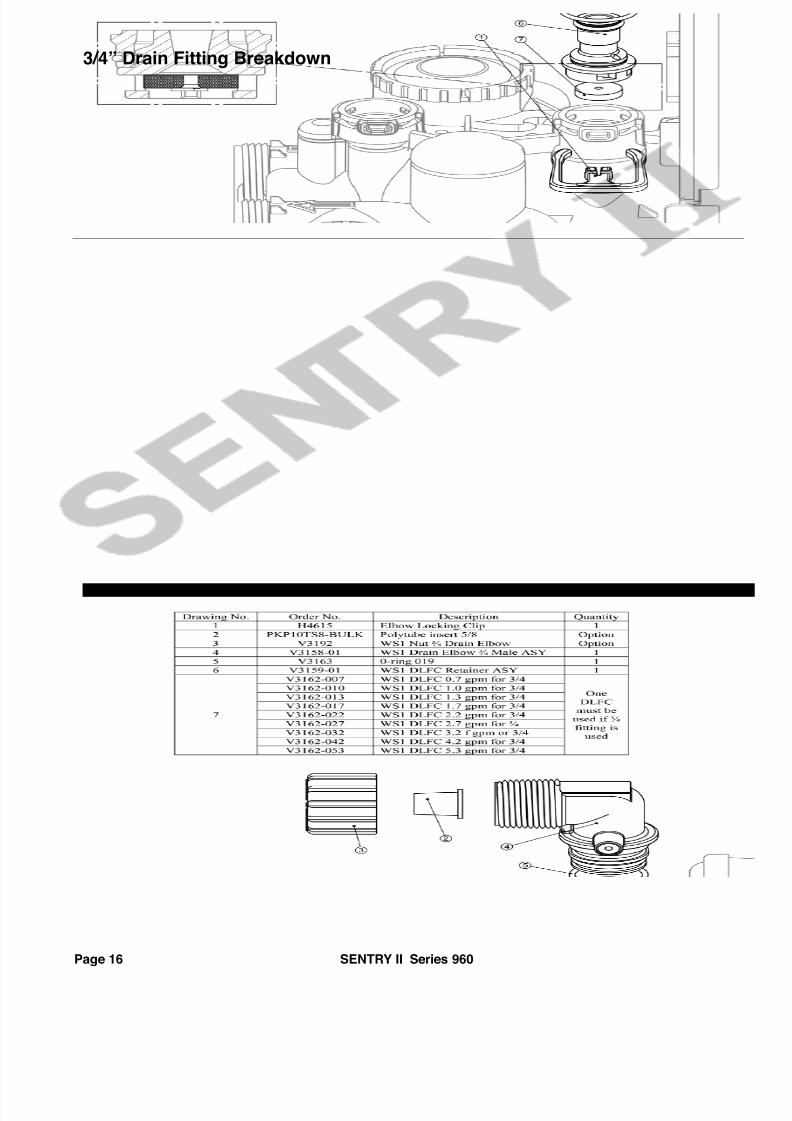
12. Drain Line Specs: If the distance from the
water softener to the drain is greater than 20’
the drain line size must be increased to 3/4”.
The threads on the drain elbow fitting are 3/4”
male NPT and can be used in lieu of the 1/2”
plastic nut and insert. If the drain line must
run overhead, the maximum height of the drain
line should not exceed 8’ above the top of the
water softener.
13. Air Gap: The drain line must have an approved
air gap to prevent the possibility of a cross con-
nection to the sewer. (see Figure 5)
14. Connecting the overflow line: The brine
overflow fitting is located on the outside of the
salt container approximately 12” down from the
top. Connect 1/2” drain tubing to the overflow
fitting and run it to the nearest floor drain. This
line is a gravity flow line and cannot be run
overhead or cannot connect to a drain that ishigher than the overflow fitting.
15. Connecting the brine line: A 3/8” brine line
approximately 4’ long is attached to the salt con-
tainer and is supplied with the tube insert (#2)
in the end of the brine line. (see Figure 6)
Unscrew the brine nut (#3) and slide it over the
end of the brine line. Insert the brine line into
the brine ftg. (#4) and tighten the brine nut (#3)
hand tight plus 1/2 turn with pliers. Caution:
Do Not Overtighten.
16. The water softener is equipped with a 15 foot
power cord with built-in transformer. Plug the
power cord into a standard (120V 60Hz) electri-
cal outlet. It will take approximately 10 seconds
before you will see the display (this is normal).
The water softener is now ready to be pro-
grammed.
Page 6 SENTRY II Series 960
Figure 4
1" Minimum
DrainDrain
Wrong Right
Figure 5
Figure 6
8/7/2019 Pacific Water - Utah - Series 960 Manual WM
http://slidepdf.com/reader/full/pacific-water-utah-series-960-manual-wm 7/24
Programming
Programming the Controller
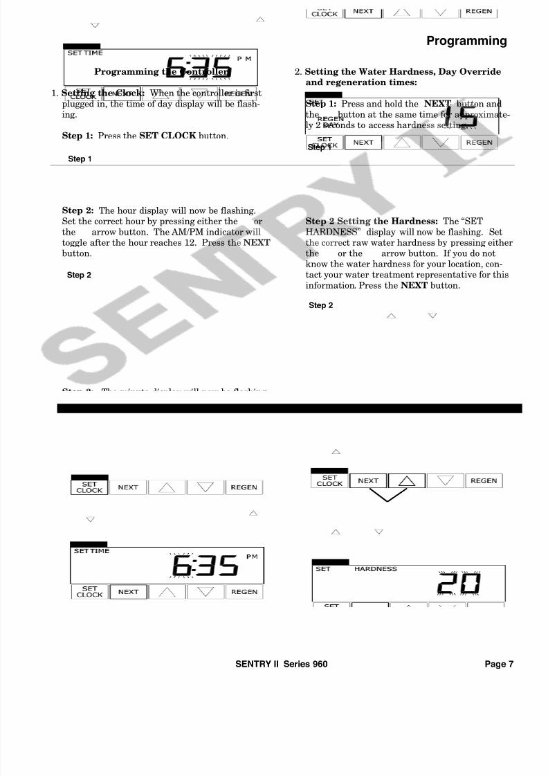
1. Setting the Clock: When the controller is first
plugged in, the time of day display will be flash-ing.
Step 1: Press the SET CLOCK button.
Step 2: The hour display will now be flashing.Set the correct hour by pressing either the or
the arrow button. The AM/PM indicator willtoggle after the hour reaches 12. Press the NEXT
button.
Step 3: The minute display will now be flashing.
Set the correct minutes by pressing either theor the arrow button. Press the NEXT button.
The display will no longer be flashing.
2. Setting the Water Hardness, Day Override
and regeneration times:
Step 1: Press and hold the NEXT button andthe button at the same time for approximate-ly 2 seconds to access hardness setting.
Step 2 Setting the Hardness: The “SET
HARDNESS” display will now be flashing. Setthe correct raw water hardness by pressing either
the or the arrow button. If you do notknow the water hardness for your location, con-
tact your water treatment representative for thisinformation. Press the NEXT button.
Step 3 Setting the Day Override: The “SETREGEN DAY” display will now be flashing. Thissetting is used to force a regeneration after a pre-
set number of days has passed regardless of waterusage. This setting can be adjusted by pressing
either the or the arrow button. This fea-ture may be turned off by setting the display to
less than 1. The default setting for this option is15. Press the NEXT button.
SENTRY II Series 960 Page 7
Step 1
Step 2
Step 3
Step 1
Step 2
Step 3

8/7/2019 Pacific Water - Utah - Series 960 Manual WM
http://slidepdf.com/reader/full/pacific-water-utah-series-960-manual-wm 8/24
Programming System Start-Up
Step 4 Setting the time of regeneration:
The hour display will now be flashing. Set thecorrect hour by pressing either the or the
arrow button. The AM/PM indicator will toggleafter the hour reaches 12. The default setting forthis option is 2:00 AM. Press the NEXT button.
Step 5: The minute display will now be flashing.
Set the correct minutes by pressing either theor the arrow button. Press the NEXT buttonto exit the programming.
The display will no longer be flashing and pro-gramming is complete.
Notes:
1. When the system is operating, one of two dis-plays will be shown, the current time of day orthe capacity remaining. Pressing the NEXT but-
ton will alternate between the displays.
2. If the system has called for a regeneration thatwill occur at the preset time of regeneration, the
words REGEN TODAY will appear on the dis-play.
3. When water is being treated (i.e. water is flow-ing through the system) the word “Softening”
flashes on the display.
Start -Up Instructions
1. Adding Water to Salt Container: Manually fillthe salt container with fresh water until there isapproximately 1” of water above the platform
located in the bottom of the salt container.
2. Manually Cycling the Controller:
Step 1: Initiate a manual regeneration by press-
ing and holding the REGEN button until youhear the drive motor turn on (approx. 6 sec.). The
“BACKWASH” display will flash until the motorstops running. The controller is now in the back-wash cycle.
Step 2: Slowly open the red inlet bypass handleby turning it counter clockwise. The handles
should now be in the same position as in Figure 1(Bypass handles may be slightly difficult to turn.)
Discolored water and air will begin to run out of the drain hose (this is normal). Leave the con-
troller in this position until the water coming outof the drain hose is clear.
Page 8 SENTRY II Series 960
Step 4
Step 5
Step 1
Figure 1

8/7/2019 Pacific Water - Utah - Series 960 Manual WM
http://slidepdf.com/reader/full/pacific-water-utah-series-960-manual-wm 9/24
System Start-Up
Step 3: Press the REGEN button. The drive motor
will run and the “BRINE” display will flash untilthe drive motor stops.
Step 4: Press the REGEN button. The drive motorwill run and the 2nd “BACKWASH” display will
flash until the drive motor stops.
Step 5: Press the REGEN button. The drive motor
will run and the “RINSE” display will flash untilthe drive motor stops.
Step 6: Fill the salt container with extra coarsewater softener salt. The amount of salt placed in
the salt container at this time is not critical; how-ever a minimum of 100 lbs. is recommended.
Note: Some of the values in the various displayexamples in this manual may not match the actu-
al values of your controller.
Step 7: If the controller has not already moved to
the “FILL” cycle, press the REGEN button. Thedrive motor will run and the FILL display will
flash until the drive motor stops.
Leave the controller in this cycle for approx. 60seconds to purge the air out of the brine valve.
Step 8: Press the REGEN button. The drive motor
will run and the “SOFTENING” display will flashuntil the drive motor stops.
Once the drive motor stops, the manual regenera-
tion is complete and the display will return to thenormal display.
Step 9: Slowly open the red outlet bypass handle
by turning it counter clockwise. The handlesshould now be in the same position as in Figure 2(Bypass handles may be slightly difficult to turn.)
The water softener is now ready for use.
SENTRY II Series 960 Page 9
Step 3
Step 4
Step 5
Step 7
Step 8
Figure 2

8/7/2019 Pacific Water - Utah - Series 960 Manual WM
http://slidepdf.com/reader/full/pacific-water-utah-series-960-manual-wm 10/24
Frequently Asked Questions
Frequently Asked Questions
1. Question:
What type of salt can I use in this softener?
Answer:
The water softener will accept any type of saltmade for water softeners; however, extra coarserock salt is recommended.
2. Question:
How full can the salt container be filled with salt?
Answer:
Do not fill the salt container more than 6” fromthe top. The amount of salt maintained in the
salt container is not critical, as long as you main-tain salt above the water level. When looking
inside of the salt container, you should always see
dry salt. If you can see water in the bottom of thesalt container, the salt level is too low.
3. Question:
Will it damage the water softener if it runs out of salt?
Answer:
Allowing the water softener to run out of salt will
not damage the water softener in any way; how-ever, if there is no salt in the salt container when
a regeneration occurs, the system will cycle asnormal but you will no longer be using softened
water.
4. Question:
If the water softener has run out of salt, are thereany special instructions before refilling the salt
container with salt?
Answer:
Before refilling the salt container with salt, thewater level must not be more than 1” above the
platform in the bottom of the salt container. If there is more than 1” of water above the platform,
bail the excess water out of the salt containeruntil there is only 1” above the platform.
After refilling the salt container with salt, do notmanually initiate a regeneration for at least 8
hours. The salt needs to sit in the water for the 8hours to become completely saturated.
5. Question:
How often does the salt tank need to be cleaned?
Answer:
Dirt, rocks and debris collect in the bottom of thesalt container (a little in each bag of salt).
Therefore it is recommended that the salt tankshould be cleaned approximately once a year.
Allowing the salt tank to run low on salt willmake this job a little easier.
6. Question:
Why do I want the water softener to regenerate at
2:00 AM?
Answer:
The water softener can regenerate at any time of
the day or night. The purpose of regeneratingduring the night is to decrease the chance of
water usage during the regeneration cycle.
7. Question:
Can I use water if the water softener is cycling?
Answer:
Yes, however any water used during the cycle will
be hard water. If hot water is used during acycle, it will add hard water into the water heaterand mix with the softened water making the
water in the water heater partially hard.
8. Question:
Why are the words “REGEN TODAY” on the dis-
play?
Answer:
If the system has called for a regeneration thatwill occur at the preset time of regeneration, the
words REGEN TODAY will appear on the dis-play.
9. Question:
Why does the word “SOFTENING” flash on the
display?
Answer:
When water is being treated (i.e. water is flowing
through the system) the word “Softening” flasheson the display.
Page 10 SENTRY II Series 960

8/7/2019 Pacific Water - Utah - Series 960 Manual WM
http://slidepdf.com/reader/full/pacific-water-utah-series-960-manual-wm 11/24
Drawings and Part Numbers
SENTRY II Series 960 Page 11
DRAWINGS AND
PART NUMBERS

8/7/2019 Pacific Water - Utah - Series 960 Manual WM
http://slidepdf.com/reader/full/pacific-water-utah-series-960-manual-wm 12/24
Front Cover and Drive Assembly Breakdown
Page 12 SENTRY II Series 960

8/7/2019 Pacific Water - Utah - Series 960 Manual WM
http://slidepdf.com/reader/full/pacific-water-utah-series-960-manual-wm 13/24
Internal Parts Breakdown
SENTRY II Series 960 Page 13

8/7/2019 Pacific Water - Utah - Series 960 Manual WM
http://slidepdf.com/reader/full/pacific-water-utah-series-960-manual-wm 14/24
Injector Assembly Breakdown
Page 14 SENTRY II Series 960

8/7/2019 Pacific Water - Utah - Series 960 Manual WM
http://slidepdf.com/reader/full/pacific-water-utah-series-960-manual-wm 15/24
Brine Elbow Assembly Breakdown
SENTRY II Series 960 Page 15
8/7/2019 Pacific Water - Utah - Series 960 Manual WM
http://slidepdf.com/reader/full/pacific-water-utah-series-960-manual-wm 16/24
3/4” Drain Fitting Breakdown
Page 16 SENTRY II Series 960

8/7/2019 Pacific Water - Utah - Series 960 Manual WM
http://slidepdf.com/reader/full/pacific-water-utah-series-960-manual-wm 17/24
1” Drain Fitting Breakdown
SENTRY II Series 960 Page 17

8/7/2019 Pacific Water - Utah - Series 960 Manual WM
http://slidepdf.com/reader/full/pacific-water-utah-series-960-manual-wm 18/24
Meter Assembly Breakdown
Page 18 SENTRY II Series 960

8/7/2019 Pacific Water - Utah - Series 960 Manual WM
http://slidepdf.com/reader/full/pacific-water-utah-series-960-manual-wm 19/24
Installation Fitting Assemblies
SENTRY II Series 960 Page 19

8/7/2019 Pacific Water - Utah - Series 960 Manual WM
http://slidepdf.com/reader/full/pacific-water-utah-series-960-manual-wm 20/24
Bypass Assembly Breakdown
Page 20 SENTRY II Series 960

8/7/2019 Pacific Water - Utah - Series 960 Manual WM
http://slidepdf.com/reader/full/pacific-water-utah-series-960-manual-wm 21/24
Bypass Valve Operation
SENTRY II Series 960 Page 21

8/7/2019 Pacific Water - Utah - Series 960 Manual WM
http://slidepdf.com/reader/full/pacific-water-utah-series-960-manual-wm 22/24
Trouble Shooting Procedures
Page 22 SENTRY II Series 960

8/7/2019 Pacific Water - Utah - Series 960 Manual WM
http://slidepdf.com/reader/full/pacific-water-utah-series-960-manual-wm 23/24
Trouble Shooting Procedures
SENTRY II Series 960 Page 23

8/7/2019 Pacific Water - Utah - Series 960 Manual WM
http://slidepdf.com/reader/full/pacific-water-utah-series-960-manual-wm 24/24


![Utah Division of Archives and Records Service...palpable injury that gives [him] a personal stake in the outcome." Utah Chapter of Sierra Club. 2006 UT 74. 19, 148 P.3d 960 (citation](https://img.dokumen.tips/doc/110x75/60200c37843a88718f1fbf36/utah-division-of-archives-and-records-service-palpable-injury-that-gives-him.jpg)


![Soldadoras - pdwatersystems.com · soldadoras wm 140 wm 180 wm 250 características modelo wm 140 wm 180 wm 250 voltaje [ v ] 110 110 / 220 110/220 fases 1 1 1 diametro de electrodo](https://img.dokumen.tips/doc/110x75/5ba485f909d3f2a9218d9d00/soldadoras-soldadoras-wm-140-wm-180-wm-250-caracteristicas-modelo-wm-140.jpg)