Embed Size (px)
Citation preview

CONTRACT REQUIREMENTS
r REPORT
CONTRACT ITEM MODEL CONTRACT NO. DATE
c
RADAR REQUIFIEMENTS REPORT
Exhibit E Para. 5.1
c
LEM NAS 9-1100 20 Dec. 62
CODE 26512
Systems Analysis and D;ynamIcs bo Performance Analysis
P& PREPARED BY:
E. Stern APPROVED BY:
J E. Stern
CHECKED BY:
PPROVED BY: A. Whitaker
the meaning of the Espionage Laws, revelation of which in any manner to a
C., Sections 793 and 794, the transmission or person is prohibited by law.
0
C I U Y Y A N A I I C I A ~ T t N C I N t t 8 l N C C O R P O I A T I O N

* R dar Requirements Report LED-540-1
It has been apparent since the early day6 of the IXM pre-proposal s tudies t h a t non-iner t ia l sensors would play an e s sen t i a l part In the navigation and guidance of the I%M vehicle. A t t h e t i m e of the submission of the I324 proposal the types of sensors that could reasonably and useful ly be employed had been n a m e d t o radars and lasere, and GAEC proposed a sensor system u t i l i z i n g both. During the LE24 negotiation period, discussion w i t h MSC personnel revealed t h a t MSC shared SATE'S opinion concerning the mquire- ment Tor non-inertial 8en80r8, bu t were not convinced that laeere wouldIbe required since they are intended primarily for s l a n t range measurements. landing can be accomplished without s l an t range eensors and the sensor systen presently recommended consis ts of radars only. respons ib i l i t i es i n the design md procurement of the IdSI radars were specified i n Pa r . 2.1.1.6 of Exhibit A (Statement of Work) for the ;PI spacecraft as follows:
Preliminary study r e su l t s indicate t ha t lunar
W s e
"The Contractor (GAEZ) shall be responsible for the detail design of the LEM Range and/or 41gle Tracking Fensor Equipment. The Navigation and Guidance S s t e m Associate Contractor (MZIP) wil l be reapansible f o r determination of the f'unctional requlre- ments of t he equipanent, insofar as they a m related t o primary guidance. The Contractor sha l l be responsible f o r determination of the Functional :equirements of the equipment t h a t are independant of application t o the primary guidance. The Contractor will be responsible f o r preparation of 'm overa l l specif icat ion for the equipment based on a l l functional requirements. "
I n order t o discharge the responsibi l i ty thus assigned, GAEC proceeeded on a two-pronged ef for t . meetings with MIT, t h e i r radar u t i l i z a t i o n concept' and appmaches t o radar design were discussed w i t h them i n considerable detail and the radar lequirements, insofar as they pertained t o primary Navigational ar?d S lidance nh%ained. study program w a 8 undertaken t o define those radar requirements imposed by back-up guidance .oncepts, configuration and performance capabilities.
In a series of technical
Concurrently, an in te rna l
Contmct No. IUS p i i o o Primary Code No. O l 3 3 Apri l lN3
REPORT ~ 5 4 ~ 1
G R U M Y A N A I R C R A F T E N G I N L E R I N O C O R P O R A T I O N ERC.7)

It is the purpose of the present report to discuss the radar utilization concepts in detail, delineate the proposed functional configuration of the radar sensor system and present a complete set of radar system performance specifications which encompsses the requirements of both the primary as vel1 as the back-up 8. & G. systems. The preliminary results of tnc internal studiem to define radar requirements v i l l be presented and will serve as the basis for the specification of radar performance capabilitiee.
The considerations and factors bearing upon the problem of hardware implementation of the radar system, a preliminary recommendation of system configuration and estimates of weight, power and reli- ability are presented in separate reports.
Particular attention has been paid to the terminal portion of the powered descent phase and to the rendezvous portion of the ascent phase, since these are the mission phases which involve t he radar to the greatest extent. Kowever, in the sections that follov, radar utilization in a l l miesion phases will be discussed in some de tail.
C R U M M A M A I R C R A F T E N G I N € t R l N G C O R P O R A T I O N

0
2. B x i z Design Concepts
A. General
The primary guidance system configuration conceived by MIT requires several t j j s of input information from sensors external t o the XMU. T'e purpose of these sensors is t o provide data that w i l l permit a more accurate computation of guidance commands than can be made with IMU aerived &ta alone (s ince the d r i f t rate of the IMU tends t o degrade the guidapce accuracy) and thus allow the lunar landing and o rb i t a l rendezvous phases of the LEM mission t o be completed within the design requirements of the nominal mission. "he data required from external sensors i s a l t i t u d e above the lunar surface, and LEI4 velocity r e l a t ive t o loca l selenocentric coordinates both of which a r e obtained from the altimeter radar equipment. I n addition, range, range r a t e , LOS angle and LOS sngular rate of the CSI4 with respect t o a LEM centered reference coordinate set are obtained rrorr, the rendezvous radar equipment. The dynamic range and accuracy requirements of t h i s data, as far as they per ta in t o the primary I?. & G. System, are derived from the MIT analysis of t h e i r guidance configuration as used i n the various mission phases. I n addi t ion t o design requirements placed upon the non-inertial sensors by the primary guidance system em- employing the IMU and AGC, requirenents obtained from the use of t he radar i n a "manual a l te rna te" primary mode as w e l l as i n the backup guidance mode must be considered i n es tabl ishing overall radar design requirements. j u s t i f i ca t ion thereof are presented i n Section 5.
These overal l requirements and the
B. I'4anua.l Alternate Mode
The manual a l t e rna te mode i s defined 5s a mode i n which the f l i g h t crew performs some of the tasks normally performed autornatically by the primary guidance system without f a i lu re of any major func- t iona l element of the primary guidance having occurred. The following system design concepts were adoped in , connection with these a l te rna te manual modes:
1. Alternate manual modes will be u t i l i z e d where the i r incorpor- a t ion increases crew safety.
2. There w i l l be a d i rec t display of sensor data where possible f o r use i n manual modes.
3. The automatic guidance modcs w i l l be compatible with nanual aonitoring and override whenever a l te rna te ~nan~a l xodes a re provided .
on t r sc t ID. NAS 9-1100 R i m r y IJO. c13
LI(C.7S C R U M M A N A I R C R A F T € N G I N € € R I N G C O R C O R A T I O N

e
0
.
*
The use of the capabi l i t i es of the ?rev wherever possible t o increase the probabilit, of m i s s i m s-ifety and success i s one of the m j o r design goals. The &Cree of securacy t o which a man can f l y the nominal missim p ro f i l e i n an a l t e rna te manual mode i s yet t o be deternined, but pending spec i f ic r e su l t s frorr, the required sirridation etudies , the primary equipment configuration will generally be expected t o provide f o r t h i s c a p b i l i t y .
The second desim concept b i ree t ly a f f ec t s the altimeter radar requirements, and requires t h a t radar derived a l t i - tude r a t e snd horizontal veloci tes must be displayed inde- pendently of the i n e r t i s l guidanze equipment. The reason fo r t h i s i s t o insure, where possible, that information from the radar sensors may be monitored and/or used by the crew before dcgadat ion or loss of t h i s information through failure of any processing ecyJipment (such as the primary guidance nomputer). descent and landing assumes tha t a t some point i n the descent t ra jec tory (which will probably be below 15,000 f t . a l t i - tude t o inslire that good data from the altimeter radar i s available), the crew can bike Over s t t i t u d e and th rus t con- t r o l of the LE4 and pcrfom a safe terminal descent and landing. t o which a nan can f l y 8 noninnl descent t ra jec tory milst be determined through simulation studies. assumed tha t a reasonable descent tra j e c t o r j can be desiLmed fo r o p t k a l use of the crew and s t i l l remain safe ly within the fuel l imitat ions, the requirements on the altk.eter radar can be stated. Frelixinary res>dts from the f ixed base ter- minal descent and landing simulation a t I G C indicate t h a t a l t i t ude , a l t i t u d e rate, and horizontal ve loc i t ies sre re- quired displays f o r the crew. Distance t o go i n range and cross range are a l so useful data. The al t imeter radar can sense the former quantitfes znd display then d i r ec t ly t o the crew. The radar data can also be introduced i n t o the AGC of the primary N . & G. system t o update the Ih lU d a t a from which d i s tance t o go can then be computed. landing s i t e w i l l serve t o monitor t h i s computed dis tance information and mke the corrections necessary t o :an2 a t t h e desired s i te .
The alternate manual mode concept fo r
As previously mentioned, the degree of accuracy
However, i f it i s
Visual s i g h t i n p of t h e
The requirement for conpat ib i l i ty of the autorzitin p idance nodes with manual monitoring and override i s necessary t o insure 'L smooth t rans i t ion from automatic t o rranuril or back- up nodes of operation. The major e f f ec t of t h i s constraint upon the radar equipnent i s t o require a continuous display of the ic.portant f l igh t pcrraneters t o t h e crev.

C. Backup Guihnce blodes
A backup guidance mode i s defined as a mode i n which the u t i l i za t ion of backup guidance equipment and/or extensive crew part ic ipat ion i n the guidance owra t ions i s occasioned by a f a i l u r e i n the primary 1'J & G system. cepts were adopted i n connection with backup guidance modes.
The following design con-
1.
2.
3.
4.
5.
The has
Crew safety i s the primary design consideration.
The backup guidance system design must provide the a b i l i t y t o abort znd return t o the CSM safely a t any t i m e i n the mission :rpon f a i lu re of any single major f'unctional element i n the prirnary system.
The backup guidance system design must provide the a b i l i t y t o abort t o a clear pericynthion o rb i t wholly independent of the primary system.
The f l i g h t crew shall be u t i l i z e d i n such a way as t o provide m a x i m u m crew safety.
The backup guihnce system shall be simpler and more r e l i ab le than the primary system.
concept t h a t crew safety i s the primary design consideration a s ignif icant e f f ec t up& the choice of whether o r not the
backup guidance system should be configured t o provide a capa- b i l i t y f o r continuing the mission t o a lunar landing despite a f a i l u r e i n the primary guidance system. t h a t the crew have the o t i o n of aborting or of continuing descent t o a 1~ l a n d i q i f : a{ e i the r the primary N & G system or the radar al t imeter (but not both) have f a i l ed and b) if radar f a i lu re occurs subsequent t o IMU updating. I n the case of a f a i l u r e in the i n e r t i a l portion of the system, the backup guidance e q u i p e n t i n conjection with the radar al t imeter can provide adequate in- formation t o permit a safe landirq. a l t imeter i n t h i s case are no d i f fe ren t from those obtained from consideration of the manus1 a l t e rna te mode.
Present thinking i s
The requirements on the radar
"lie singie f a i lu re of any major f'unctional element i n the primary N & G system may not disable the en t i r e primary system, and the backup guidance equipment can possibly be designed t o provide the ?unctions necessary t o supplement the remaining primary ele.:nents i n the backup node. ( A s described above f o r the case of an IMU f a i l u r e i n the la t te r portion of powered descent.) f a i lu re of the rendezvous radar w i l l require a specif ic backup,
However,
Contract NO. rim g-iioo MW*T m - 540-1 3 ~ p r i i 19G3 fihary No. C l j D A l L
G R U M M A N A I R C R A f l E N G l N E t R l N O C O R P O R A T I O N
such as, f o r instance, a CSM mounted tracking radar and a communication l i n k between the LEN and CSM. t a t i ons f o r use by LE3 will then be carr ied out on the CSM com- puter and transmitted t o LEI4 via the cornunitation l ink. The requirements on the rendezvous radar i n the backup guidance mode are the same 3s those previously described fo r the mnual alter- note mode.IPatracking radar i s placed on the CSM t o backup the LE24 rendezvous radar, it would appear very desirable for these equipments t o be ident ical ly configured.
The guidance cmpu-
Use of the f l i gh t crew i n the backup guidance scheme must take in to account the crew task load and performance capabi l i ty i n determining t h e computation complexity and degree of automat- i c i t y of the backup system. t ions leads t o the conclusion that the rendezvous radar anfenna should be gimbaled. the task of obtaining suf f ic ien t , accurate radar data without the use of the AGC of the primary N & G system prac t ica l ly impossible.
A d i rec t r e s u l t of these considera-
The use of a f ixed radar antenna would make
The requirement t h a t the backup guidance system be simpler and more r e l i ab le than the primary guidance system insures that the r e l i a b i l i t y goals f o r crew safety a re met without paying a la rge weight penalty f o r ca r ry iw standby of redundant equipment. Thus, as far as the radar e q u i p e n t i s concerned, it appears very desireable t o design the two radar equipments such tha t one is inherently capable of providing a backup fo r the other, mther than including a standby radar on the LEN expressly for an s l t i m - eter o r a rendezvous backup function. success and mission safety requirements lead t o the conclusion that these requirements can be most readi ly s a t i s f i e d by providing a backup alt imetry m c t i o n i n the rendezvous radar equipment which will pencit safe landing w i t h the use of the i n e r t i a l por- t i on of the primary system despite the l o s s of the al t imeter radar, and by backing up the LEbl rendezvous radar wi th a similar radar on the CSM. The use of the rendezvous radar as. an altimeter dur- ing power a t descent has the additional advantage of providing a t h i r d source of a l t i t ude data t o decide whether the INU o r the altimeter i s i n error. If there is a s ignif icant discrepancy i n the t w o outputs, t h i s information woiiid then ins-ire tkt i f the crew decides t o continue the mission t o a lunar landing, they would do so with the properly functioning equipment, and thus increase the probabili ty of surv iva l as w e l l as of mission success.
Consideration of mission
,
G R U M M A N' A I I C R A f I E N C 1 N L L I I N G c 0 P 0 I A 1 I O N w c . n

3. MISSION mFIm A - General
The primary function of the radar is t o provide data fo r the L6M guidance system i n both the primary and back-up modes. This data may be processed by the AGC for u t i l i z a t i o n i n automatic guidance phases or it may be displayed t o the crew t o provide the capabili ty of performing t he guidance operations i n manual, a l t e rna te or back-up modes. m e n t s are d i r ec t ly related t o the guldance.schemes used i n the various mission phaaes. In the discussion t h a t follows, the mission profile W i l l be described w i t h respect t o requirements for radar data, and the results of adar u t i l i z a t i o n studies pert inent t o the par t i cu la r phase under discussion vi11 be presented. which is discuseed separately i n Section 4.
Thus, the radar require-
Excluded fm t h i s section is the rendezvous phase,
3 - Separation f m m CSM
Separation of the LEM from the CSM takes place i n lunar orbi t . The LlBf RCS i e u t i l i z e d t o apply the separation thrust, to achieve a separation distance of about 100 feet. There is no requirement for radar data during t h i s phase, except possibly fo r the purpose of checking out those radar f’unctione which operate i n conjunction with a transponder on the CSM. of the close proximity of t he two vehicles, it may also be possible to check the non-transponder Rrnctions by skin-tracking t h e CSM.
Because
C - Injection i n t o Transfer O - b i t
I t does not appear that radar data is required In this phase.
D - Coast t o Pericynthion of tie T *ansfer O f b i t _I-
I n order t o es tab l i sh the orb i t conditionf 2‘ i l t i ng f ’ m m . t h e in ject ion thrust , the range and xange rate 1; the CSM relative t o the LEdJI should be determined as a function of t i m e . A study is presently underway t o es tab l i sh the accuracy require- ments on range and range rate sensing t o allow reliable prediction of per icynthim a l t i t ude . ind ica te t h a t l$ range measurement e m r leads t o
P r e l M n a r y results

approximately 5000 feet uncertainty i n pericynthion, and tha t this is rglatively independent of range from inject ion up t o about 30 cent ra l angle trammed.
About 10 minutes p r io r t o reaching apocynthion, the altitude, and possibly the velocity, measuring capabi l i ty of the 88asor system should be verified. This results i n an altitude meamxe- ment range of about 70,000 feet, f o r a t r ans fe r o r b i t starting a t 80 H.Mi and tennination at 50,OOO feet. which provides t o t a l LF# velocity relative t o loca l coordiastes such a6 for example a three beam doppler, the velocity meaeure- ment range should be about 5700 fps, which is the horizontal component of LEM velocity near pericynthion.
For a sensor
E - %wxed Descent
Po=red descent i s inLdatd at pericynthion (50,000 feet) of the transf'er o fb i t . data for the guidance and control system is derived f'run i n e r t i a l sensors. The e r ro r s i n t h i s data increase both In absolute value a6 w e l l as i n terms of percentage of measured values. i n cummulatively larger errors i n velocity and posit ion data. Errore i n measurement of lunar orbit altitude t r ans l a t e d i r ec t ly in to e m r s i n knowledge of altitude relative t o loca l t e r r a i n and becones pmgressively m i o r e s ign i f icant as a l t i t u d e decreases. Terrain var ia t ions introduce additional perturbations into knowledge of altitude above the lunar surface, eince i n e r t i a l senaor cannot detect t e r r a i n changes.
During the early portions of the descent,
Clearly, platform misalignment and d r i f t results
For the above reasons, direct sensing of LIS4 posit ion and veloci ty appears t o be prerequiei te t o achieving successful descent ,and landings. u t i l i z a t i o n fs i n updating of i n e r t i a l equipnent. technique generally leads to optimum knowledge of LEX dynamic parameters, since the good high frequency content o f ' i n e r t i a l l y derived data complements t h e good l o w frequency content of nan-iner t ia l sensor data. F'urthem're, subsequent t o the i n e r t i a l updating of t he i n e r t i a l equipment, f a i l u r e of the non-inertial sensors does not necessarily requ i r e that +&e mi6sion be aborted. "he concept proposed by KIY involves mixing of i n e r t i a l and non-Inertial data i n the AGC accoralng t o the statistical varlaaotr o f t h e error dis t r ibut ions. Since the q u a l i t y of inertial data degrades with t i m e and t h a t of non-inertial d a t a improves, progrepsively more veight i c attached t o non-ine-tial sensor data as the descent progresses.
The primary mode of sensor data "his
Contract No. mAS gllo0 RtPOnT LED-540.1 Primary Code 190. CU.3 DATL 3 AprU 1963
G I U M M A N A I R C R A F T € N G I N € E I I N G C O R P O R A T I O N cmc-7s

It i s ant ic ipated tha t t h i s data mixing will comence a t an a l t i t u d e of about’25,OOO feet, and that a t about l5,OOO feet, altimeter data will be weighted a t almost lM$. of r e l a t ive weighing of velocity data have not been obtained as yet at GAEC.
The pmblem of determining the e f f ec t of t e r r a i n var ia t ions during the terminal portion of the poweRd d e s c h t has been the object of considerable a t ten t ion and etudy. m s u l t e of this study are presented i n Appendix 1. following t e r r a i n s i tua t ions w e r e considered In the study. Star t ing at distance of 20 N.M from the nominal hover point, at an altitude of about 18,000 feet, constant Slope6 of + 3 and i n i t i a l altitude and vertical velocity e m m of 5W- feef and 3 f p s were investigated. Single inf lec t ion points were thenL introduced a t varlow points i n the terminal portion of the t ra jec tory p d seve 1 comb a t ions 06 elopes cmiihered. These were +3 and and +3 and +15. The efmt of +3’ slopes and-initial-conditl& em=-is shown i n Pigums-Al-3 through Al-13. Essentially it Y ~ B . shown that a RU updating altimetry data and two point prediction of landing site a l t i t u d e always resulted in acceptable final conditions a t hover a t no s igni f icant n V penalty. condition e m r s i n a l t i t ude were of no consequence, but i n i t i a l vertical velocity ermrs did lead t o errore i n final vertical and horizontal velocity. veloci ty updating of the IMJ may be a requirement. Figure 5 Al-14 and 15 bhow the e f f e c t of a double elope surface. Again, for +3 slopear there are no s igni f icant final condition e m r s o r &V penalties. Thf3 effects of terrain variat ions including double slopes o f +3 AL.14 th roup AI.-16, and th&e n?fe-?ring to double slopes of +3 and +15 are shown i n Figures Al-li’thmugh A1-20 . A . general Fonclusion of these studiee I s that a l t i t u d e updating of the M I is generally sat isfactory, except when the ground slopes become unreasonably steep. t h e attempt t o accrnmodate the t ra jec tory t o thebe t e r r a i n var ia t ions was unsuccessf’ul, i n t h a t intersect ion the lunar surface occurred p r io r t o reading zero ver t i ca l velocity. Further s tudies of this problem a re In progress t o determine the exact l imitat ions of t he upd.ating and prediction pmceduE desired, and t o look in to other techniques and mthods.
Estimates
The preliminary The
9
I n i t i a l
This indicate8 t h a t ve r t i ca l
and +6 a= shown i n Figures
- For such extreme cases,

F - Hover and Touchdown
The phase of the mission ext--iding fram hover a1 (approximately 1,000 feet) t o touchdown has not yet been defined i n grea t de t a i l . Some general observations can be made however. working properly the terminal descent from hover can be acccnnplished without a l t i t ude and ve r t i ca l velocity data f m m external sensors, provided the 1W w a s updated at some previous point i n t h e t ra jectory. Horizontal velocity data f r o m non- inertial sensors may,however, be requized since a) there is a t i g h t e r tolerance on horizontal than on ver t i ca l velocity at landing and b ) horizontal velocity changes over a greater range of values during the f i n a l portion o f the powered descent than does ve r t i ca l velocity BO that even updating ear ly i n that phase s t i l l leaves the poss ib l i ty of excessive e r ro r s being
ude
If the primary Navigation and G*:idance System is
accumulated by t he IMI.
In the event of failure in t he i n e r t i a l o r computing portions of the primary navigation and Guidance System occurring during o r j u s t p r io r t o the hover phase, there may be incEased mission safety i f the landing Is completed rather than the mission being aborted. data must be provided and i n a form meaningful to the crew and &table f o r d i rec t display. simulation has not ye t been perfomed t o indicate i f IEM velocity data relative to body coordinates is a d e q k t e to pemit successful landing o r i f resolution in to loca l selenographic coordinates ie required. not appear that the hover and touchdon phase requirements w i l l impose any l i m i t i n g tolerances on the non-iner t ia l sensor capabi l i t i es .
Under these conditions, non-inertial
LSufficient study and
In any event, it does
On the lunar surface, t h e rendezvous radar can .be used t o t rack the CEM as it passes over the horizon and comes in to v i e w of the IEM. t o enable tne LZM location -elative t o the CSM orbit t o be detemined. The data can be used as a backup t o the opt ica l tracker, and, by comparison with OW measurement can be used t o determine if the rendezvous radar i s working properly.
This tracldng will be done only long enough
Contract No. IUS ~ U O O bimary Code No. O l 3
C R U M M A N A I R C R A F T L N C 1 N t t R I N G C O R P O R A T I O N CNS.lS

The gimballed radar can also a i d i n aiming t h e OW by locking on t o t h e CSM and displaying the angles with respect t o the IEM. Since the o r b i t of t he CSM i s known with respect t o i n e r t i a l space, a igular data from the radar should be suf f ic ien t t o calculnte the LEM position with respect t o the CSM.
H - Launch
Cince the ascent i s pre-pmgrammed i n both. the primary and backup modes, non-inertisl data is not required. If t he launch i s made a t the proper time, t he i n i t i a l t h rus t will i n j e c t t he LEN in to the t r ans fe r o rb i t . However, i f there i s a t i n ing ermr, the I X M may have t o e n t e r a parking o rb i t and await the proper inject ion conditions f o r transfer t o the CSM. 'Flese conditions can be determined from data obtained by tracking the CSM. i f t h e p r i m r j guidance system i s functioning properly, the LEM o rb i t i s accurately known and only the phasing or r e l a t ive selenocentric angle between 1334 and t h e CSM need be known. If t h e primary guidance
. system has f a i l e d and the LEM i s on backup guidance, t h e e r ro r s a t t h rus t t emina t ion will generally be l a rge r and angle and range data may beneeaedfor t h e computation of the proper phasing.
I - Ascent Eoast and Mid-course Correction
Tie ascent coast phase ca r r i e s the :;EM from burnout a l t i t u d e of t h e powered ascent t o within homing rendezvous range of t he CSM. Uuring t h i s phase, it i s ant ic ipated t h a t non- i n e r t i a l data referr ing t o r e l a t ive position and veloci ty of t h e L,EM and the CSbl will be T-equired t o reduce the e f f e c t of burnout e r ro r s on the A V penal t ies during homing rendezvous.
For powered ascent and coast phases performed under the direct ion of the primary Navigation and Guidance : ' : I s t e r n , t h e ermrs a t burnout w i l l be comparatively smll and the problem of perf3rming a mid-course correction I.elati-Jely easy . Cince the AGC i s avai lable f o r computation md data snoothing, the type of data can be e s t r i c t e d , t he number of measurements can be f a i r l y large -tnd t h e mathematical opemtions on the data can be extensiie a n d sophisticated. Fince MIT haE the responsibi l i ty fQr devising t h e mid-course c o r r e c t i m technique i n the primary node, no e f f o r t has been mrrile st 3AEC t o s t u Q t h i s probleii.
C P U M M A N A I I C P A I T E N G I N E E R I N G C O P P O I A T I O ~

For the case of a f a i lu re i n the p r b a r y Navigation and Guidance, ,however, the s i tua t ion is qui te different. If t h e f a i lu re occurs pr ior t o ascent, t he powered ascent must 'be perfonxed on back-up guidance equipment, and thus the burnout errors can be qui te large. computational f a c i l i t i e s f o r mid-coui-se correction determination w i l l be qui te l imited, s ince it i s highly desirable t o keep t h e backup guidance equipment as simple and reliable a6 possible. Thus a mid-course correction technique requiring as f e w measurementE; as possible and involving a minimum of computation f o r t h rus t from the meamred data is essent ia l .
Furthennore, t h e
deriving t h e correct ive
A study w a s undertaken a t GAEC t o develop a correction technique meeting the above requirements and t o evaluate i ts effect ive- ness. In order t o minimize the number of measurements t o be made, various conibinations of relative data were investigated w i t h regard t o a t ta inable accuracy. t h e measurement and applying the correction was a l so studied. The computational regime was simplified t o the extent of u t i l i z i n g a simple l i n e a r combination of measured quant i t ies , using non-time varying coeff ic ients . not complete, some preliminary r e s u l t s can be ci ted. . Table 1 shows t h e distance of c loses t approach obtainable on a coasting t r a j ec to ry with cer ta in combhatiomof measument errors. This value is obtained by multiplying t h e number of feet given i n the Error column by t h e multiplying fac tor appearing i n the column hexded by t h e pa r t i cu la r combination of measurement errors under consideration. The results are given f o r pe r fon ing the measument a t 1750 and 2000 second6 f r o m burnout, which f o r a nominal Hohmann transfer corresponds t o about 35 M.W. and 25 N.Mi. distance fram t h e CSM. course, considerably larger , but t h e e su l t i ng ermrs are approximately the same. Come general conclusions t h a t can be drawn f r o m the data presentedare t h a t a) better r e su l t s are obtained if the corrections are performed l,ater i n time, b ) range rate and angular measurements seem t o y ie ld smaller miss-distances f o r comparable measurement e r rors , c ) even comparatively large measurement erm rs permit mid-c ourse corrections adequate t o place the LEM within e f f i c i e n t homfnd range of the CSX.
The time of perfonning
Although t h i s study, too, is
For of f nominal t r a j ec to r i e s , these distances are, of
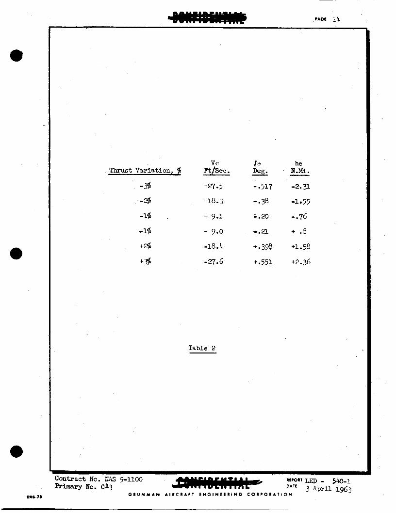
Appendices 2, 3 and 4 present a more detailed picture of the r e su l t s obtained so far from the mid-course correction studies. In par t icu lar , Figures 113-1 and A2-2 give the A:! penalty f o r making a ni2-course correction f r o m o f f -nominal t r a j ec to r i e s corresponding t o +l$ mc! +$ t h i u r t deviation during powered ascent. 'Tic buniout ermrs resul t ing f'mn various values of off-nomin3,l thruzt are l is ted i n Table 2. TIE significance of these results are iliscumed i n Lrme more cletcil i n Scc t im 14.

IL 0 0 k M d 0 U r i
3- l-ii
r l d c u r i
L n ? C C u
In 9 T U
L n d U
?
II u P
ui .ui 0
o( ooz! ."
I
d
C I U M M A N A I I C I A f l E N O l N L t R l N O C O I P O I A T I O N
Ve Thrust Variation, $ Fthec.
-% tr7.5
-8 +18.3
-1% . + 9.1
+I% - 9.0
+$ -18 4
Table 2
- .517 -.38
G . 2 0
+.a +.398
+ e 5 5 1
he NOM. - -2.31.
-1 55
- .76
+ .8
+1 . 58
+2.36
Contract r h . IUS 9-1100 REPORT 510-1 3 A W 1 1963 DO. 013 DATE
G R U M Y A N A l R C R A f T E N G l N E E R l N ~ C O R P O R A T I O N
4. Rendezvous
A . General
One of the most significant factors i n establishing cer ta in aspects of the radar configurations proposed herein, has been the concept of an active homing phase during the terminal por- t ion of the ascent to rendezvous f l i gh t . phase is recommended by G A E as the basic rendezvous guidance mode primarily to allow the design of an alternate m o d e which provides f o r maximun! crew participation i n the operational procedure. philosophy t o consider t h i s "manual alternate" mode as tbe first tier back-up mode i n the event of a non-radar-conmcW failure of the pr ima4 N. 8~ Gsystem. approach, it i s recommended that the primary rendezvous guidance mode be fully compatible with the alternate and back-up modes to the extent of performing automatically (if the primary m o d e is automatic) exactly the same operational steps as the crew w o u l d perfom i n the al ternate back-up modes. thecrew i s capable of monitoring the progress of the rendezvous phase and of determining if it proceeds properly, b) the dynamic and kinematic conditions existing a t any instant are suitable f o r changeover to the alternate or back-up m o d e so tbat the crew i s prepared t o take over the operation and c o n t i w it to a suc- cessful conclusion without any mental reorientation,and astronauts need be trained f o r only one basic rendezvous ma~~!u- ver t o monitor and perform, and w i t h respect to which to make operational decisions.
A terminal homing
It i s then a logical extension of such a design
As a consequence of this
This assures that a)
d)
"he e f fec t of adopting the concept of a t e r m i n a l homing phase which allows act ive crew participation i n an alternate mode, and requires such participation i n a back-up mode occasioned by failure of the primary N. & G. system, i s that of r equ i rbg I& rate measurenent capability i n the rendezvous radar and the capabili ty of direct ly displaying radar data. modes of the rendezvous maneuver s h d d be so fashioned as to take f u l l e s t advantage of the capability thus provlded.
A l l the
I n the succeeding paragraphs, the rendezvous concept recolrmended by CABC w i l l be discussed i n d e t a i l and It Kill be demonstrated Lbt t h i s +vech;lii";e hbs the e,Vect c? allc~wiag a s i g d f i z a z t relaxation i n the re&red tolerances of ascent tradectory con- t r o l .
B. Rendezvous Maneuver
The basic feature of the terminal homing phase In the rendezvous maneuver is that the LEI4 essentially flies a col l is ion course to the CSM. This character is t ic is achieved by keeping the i n c r t i a l rate of the LOS t o the CSM below a given threshold value, which is established by the a b i l i t y of a sensor t o measure inertial rate.

t
A s recommended by GAEZ, the terminal homing rendezvous w i l l be perfomed i n a series of operational steps as follows:
1.
2.
3.
4.
Range t o the CSM is m e a s u r e d continually during the coasting ascent f l i gh t . the CSM is measured and thrust is applied t o reduce t h i s rate t o the threshold level.
A t a given range fran the CSM, IDS rate to to the LOS
Following Ix)s rate reduction, range rate with respect 4~ the CSM i s measured and th rus t applied along the US dil.ec- t ion u n t i l range rate 'Ls reduced t o a predetermined value appropriate t o the range a t which t h r u s t was in i t ia ted .
The UW i s allowed t o coast u n t i l the next range check point is reached. Steps 1 and 2 are then repeated.
This procedure is continued through a number of range check points until f i n a l docking range and near zero re la t ive velocity are attained.
The a t t i t ude maneuvers required of the LE24 as it proceeds through the above outlined operational sequence are as follows:
1. With the rendezvous radar locked on and tracking the CSM, the LEM a t t i t ude is adjusted t o nu l l the radar antenna gimbal angles. along the Lx)s t o the CSM and gives the crew d i rec t CSM visi- b i l i t y through the forward cabin windows.
This results i n the LlW Z-ax ls being directed
2. The direct ion of the normal component of the relative velocity vector is established from measurement of the imrtial rates of the antenna. the LE24 X and Y axes, then inertial gimbal rates are d i rec t ly proportional t o components of the relative inertial velocity vector along body X and Y axes. the Z axis u n t i l one of the gimbal rates reaches the measure- ment threshold value. A s a result, the body, e x i s correspond- ing t o the gimbal a x i s i s now aligned with the net normal component of relative i n e r t i a l velocity. axis is now applied t o nu3l the indicated Ix)s rate, and thus eliminate the normal velocity component. are used In tnis phase.
If the gimbal axes are aligned parallel t o
The LEX is rotated about
Thrust along that
The BC8 engines
3. Range rate reduction t o the value commensurate with the range a t which the correction i s made, is perfonaed by the Z a x i s RCS engines, vith the Z axis aligned t o the Lx)s to the CSM.
The concept of multiple thrust phases rather than continuous con- t r o l was adapted f o r several reasons. For one, the range versus raw rate regime for multiple t h r u s t s is a simpler one than f o r
Contract No. NAS 9-UW REPORT - 5 b - 1 Primaq No. 013 DATE 3 April 1963
G P U M M A N A I R C R A F T t N G l N L L R l N G C O R P O R A T I O N C:*C.TS

continuous thrust , and lends itself more readily toward a display presentation tha t the crew can follow i n a ma,m.al mode. Further- more, during some back-up modes involving radar failure, s-- era l of the measurements required f o r successful rendezvous must be performed visually by the crew, and the coasting t i m e between thrust applications allows this t o be accomplished.
c. Rendezvous study Results
A study was undertaken t o analyze the various aspects of #e tenninal homing re&zvaus maneuver described. above. was the relationship between AV required to rendezvous and the range of i n i t i a t i o n of the homing maneuver. Also the effect of US rate measurement accuracy on the capabili ty of completing the rendezvous was investigated. range spacing and the range rate limits a t these ragges were also studied.
Of interest
The number of thrust phases, their
Initially the thrust spacing used i n the LIM proposal phase was employed. This regime can be described by the following table:
Range N. M i .
30 20 10 4 1
.08
Range Rate f p S
- 200 120
60 20 0
A t 30 N.Mi., only a WS rate correction was made. check-points, i n addition t o the Ixls rate correction, the range rate was reduced t o the value given i n the table. worked sa t i s fac tor i ly for some ascent tradectories, but failed to r e su l t i n rendezvous f o r others.
A t subsequent
The regime
The reason f o r such failure t o complete the maneuver was due t o character is t ics of the par t icular ascent t ra jectory tried. generally happened was t h a t the range rate a t the first check- point (20 N.M .) was already below the required value, and thus no correction w a s made. reach apocynthion and the LEN would start moving away from the CSM before the next checkpoint was reacbed. w o u l d nexer be achieved. maneuver w o u l d always termbate properly, tmmodifications in the range - range rate regime had t o be made. To assure that suff ic ient closing rate existed a t all times, a rnirdmum 8s well as a maximum range rate had t o be specified at each checkpoint. Thus, if the range rate existing a t a given range cbdqpoint is below the minimum, thrust i s applied towards the CSM to increase it to the minirmnn level, w h e r e a s If range rate is above thc maxi- m, thrus t is applied away froan the CSM to reduce range rate to the Imximum lavel.
What
'Fi coasting traJectory would then
Tbus rendezvous I n order to assure that the homing
C R U M M A N A I R C R A P T L N G I N t t @ I N O C O R P O R A T I O N
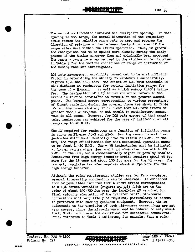
The second modification involved the checkpoint spacing. spacing i s too Large, the normal kinematics of the trajectory could reduce the relative range ra te to zero and reverse the direction of relative motion between checkpoints, even if the range rates w e r e within the limits specified. the checkpoints had t o be spaced more closely during the early phases of the haming maneuver than had original ly been proposed, The range - range rate regime used i n the studies so far is given i n Wble 3 f o r the various conditions of range of i n i t i a t ion of the hamlng maneuver investigated.
If t h i s
Thus, i n general
IDS rate measurement capability turned out to be a s igni f icant factor in determining the a b i l i t y t o rendezvous successfiiuy. Figures As-2 and A5-5 chow the e f f ec t of m.5 rate threshold on miss-distance a t rendezvous f o r various In i t i a t ion ra es f o r the case of a Hohmann as w e l l as a high energy ( 1 3 ) trans- fer. e r rors In i n i t i a l conditizns a t burnout of the powered ascent phase. The burnout errors corresponding t o various percentages of thrust variation during the powered phase are shown In Table 2. For the cases studied, it i s clear that IDS rate errors of
greater than 0.2 mr./sec. do not result i n satisfactory r enbz - vous i n all cases. However, f o r ILE rate errors of that ma&- tude, rendezvous was achieved f o r the case of i n i t i a t ion a t all ranges up t o 40 N.Mi.
me designation of + @ thrust variation refers to the
The AV required f o r rendezvous as a function of i n i t i a t ion range is shown on Figures A5-3 and A5-6. For the case of coast tra- jector ies which would nominally com to w i t h i n 20 B.Mi. of the CSM, the range of i n i t i a t ion f o r most economical operation seems to be about 14-20 P I - M i . The 2 tmjectories must be i n i t i a t e d a t longer ranges since they would not otherwise come within 20 N.Mi. of the CSM, and a commrjnsurately higher AV penalty results. Rendezvous from high energy transfer orb i t s requires about 40 f p s more f o r the I$ case and about 150 irps more for the 2$ case. The nominal, i m p u l s i v e t ransfer requires about 40 f’ps more f o r the high energy transfer.
Although the radar requimments studies are fer from complete, several interest ing conclusions can be observed. A s evidenced from AV penalities incur- from burnout errors corresponding to a k34 thrust variation (Irigunr A5-3,b) which are on the order of about 250-300 f‘ps over the ImpuIsive AV ~.eqplred f o r final velocity adaptation of the transfer’ orbi t , mid-course corrections will very likely be required, par t icular ly if ascent i s performed with back-up guidance equipment. quirements on the precision of such mid-course correctlo- are not very severe, since the miss-distance m?ed be reduced to only about 10-15 N.Mi. t o achieve the conditions f o r successful rendezvous. Thus, reference t o Table 1 indicates, f o r example, that a radar
However, the re-
C R U M Y A N A I R C R A F T E N G l N C C R l N C C O R P O R A T I O N ENC-IS

RAPXIE RATE BOUNDS AT REXDEZVOUS W E TEST POINTS
I n i t i a l Rende zvous Range T e s t Range Rate Bounds, Range, N.Mi. Point, N.Mi . f t . /sec.
40 350 - 250 35 325 - 225
40 30 300 - 200 20 200 - 120 10 120 - 70
4 70 - 30 1 30 - i o
I
30
30 25 20 1 5 10 4 1
300 - 200
200 - 120 170 - 100
70 - 30
270 - 150
120 - 70
30 - 10 - --
200 - 120 170 - go 130 - 75 a 100 - 60 i 20 I i ii-7 4 1
70 30 - - i o 30 - -_. I - !
! i 14 160 - 95 i ! 1 0 120 - 70
8 100 - 60 4 70 - 30 1 30 - i o I
14
Contract 110. N U g-llOO Primary Code NO. 013
R ~ C O R T LED-540-1 3 A p r i l 1963
G R U M M A M A I R C R A l T t N G I N t f R l M G C 0 R ? Q U A T l Q N E I I ~ . ~
~110.71
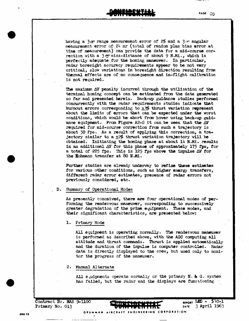
having a '3cr range measurement e r ror of 246 and a 3.7- angular measurement e r ror of 24 m r ( t o t a l of random plus bias er ror a t t i m e of measurement) can provide w data f o r a mid-course cor- rection with a 3 bmiss-distance of about 9 N.Mi., which is perfectly adequate for the homing maneuver. I n particular, radar boresight accuracy r@quirements appear to be not very c r i t i c a l , slow variations i n boresight direct ion resulting from thermal ef fec ts am of no consequence and in-f l ight calibration is not required.
Tfie maximum AV p n a l t y incurred thrargh the u t i l i za t ion of the teminal homing concept can be estimated f r o m the data gemrated so far and presented herein. Back-up guidance studies perf'oxmed concurrently with the radar requirements studies indica* t h a t burnout errors corresponding t o 2% m s t variat ion m p n s e n t about the limits of epors that can be expected under the worst conditions, whlch would be abort from h w e r using back-up guid- ance equipment. From Figure A2-2 it can be seen that tbe AV required for mid-course c o m c t i o n froan such a tra;)cctory is about 50 fps. A s a msult of applying t h i s correction, a tra- jectory s u r t o a +2$ thrust variation t ra jectory w i l l be obtained. In i t i a t ing the homing phase at about 1 4 N.U. results i n an additional AY for t h i s phase of approximately 175 fps, for a t o t a l of 225 f p s . the Hohmarul transfer a t 80 B.M.
This is 125 Pps above the impulse AV for
Further studies are already underway t o Mine these estixrates fo r various other conditions, such as higher euergy transfers, different radar error estimates, presence of radar errors not previously considered, etc.
D. Summam of Onerational Modes
As presently conceived, there we four aperational modes of per- form- the rendezvous maneuver, corresponding to successively greater degradation of the prime equipment. their signif icant characterist ics, are presenWbelow:
These m o d e s , and
1. Primam Mode
A l l equipment is operating normally. is performed as described above, with the AGC computing all attitude and thrust commnds. ' b u s t is applied aukamtically and the duration of the impulse is computer controlled. Radar da ta i s d i rec t ly displayed t o the crew, but used only t o moni- tor the progress of the maneuver.
The rendezvous maaeuver
2. M a n u a l A l t e r n a t e
All e-&ments operate normally o r the primary N. 8 G . system has fafied, but the radar and the displeys are function%
b m t r a c t No. NAS g- l lOO R t p o f i T LED - 5'+0-1 PrLmery No. 013 DATE 3 Aprll 1963
G R U M Y A N A I R C R A F T E N G l N t t R l N O C O R P O R A T I O N

properly. t o perform the correct im maneuvers. Alignment of the Z - a x i s with the Ix)s is acccanglished by reference to the gimbal angle display. rate display shows one component t o be zero. along the other axis u n t i l tihe display shows that component of IXIS rate to be nulled. posit ive or negative Z - a x i s u n t i l one of the range rate limits f o r that rage i s attained.
From the range display, the crew determines when
The LEX i s rotated abaut tihe Z - a x i s un t i l the IDS Thrust is applied
Thrust is then applied along either the
3. CSM Radar Util lzat ion Mode
!he IJM rendezvous radar has failed, but all other equipment is functioning normally. The LeM Z - a x i s I s visually directed along the Ix>s t o the CSM using the OMU and flashing lights on the CSM. LlSf crew from the CSM, as obtained from tbe CSM tracking radar. Pr ior t o reaching the first checkpoint, the LEM crew determines the direction of the normal component of relative velocity by tracking the CSM at the center of the OMU crosshairs and rotat ing the LIB4 about the Z - a x i s u n t i l the ralstive motion of the CSM against i t s background ( w h e t h e r it be star back- ground or lunar surface background) occurs along one of the coordinate axis of the OMU r e t i c l e . The impulse t o be applied t o null the normal component of velocity i s obtained from the CSM via the communication l i nk and epplied along the body axis corresponding to the r e t i c l e axis aligned w i t h the normal velocity vector camponent. direction of the IOS is UkeKLse obtained from the CSM.
Ran@;@ and range rate data is communicated t o the
The impulse t o be applied i n the
4. Manual. - V i s u a l Mode
Both radars or the LEM radar and the communication l i nk have fai led, but all o t h e r equipment is f’unctioning normally. Approximate range and range rate data can be obtained by camgutation from the AGC. as i n Mode 3 above, but i n addition LOS rate magnitude must be determined. CSM i s seen against a star background. the rate a t which the stars move relat ive t o the C W along tbe OMU r e t i c l e axis can be estlmakd n n A n thmst Lrzpdse eppXed t o null it.
IOS rate direction i s ascertained
This can be performed visually only i f the Under those conditions,
G R U M M A N A I R C R A f T L N G l N E C R l N G C O R P O R A T I O N CNC.73
5. Pref ormance Requirements
A. Functional Description of tbe adar Configuration
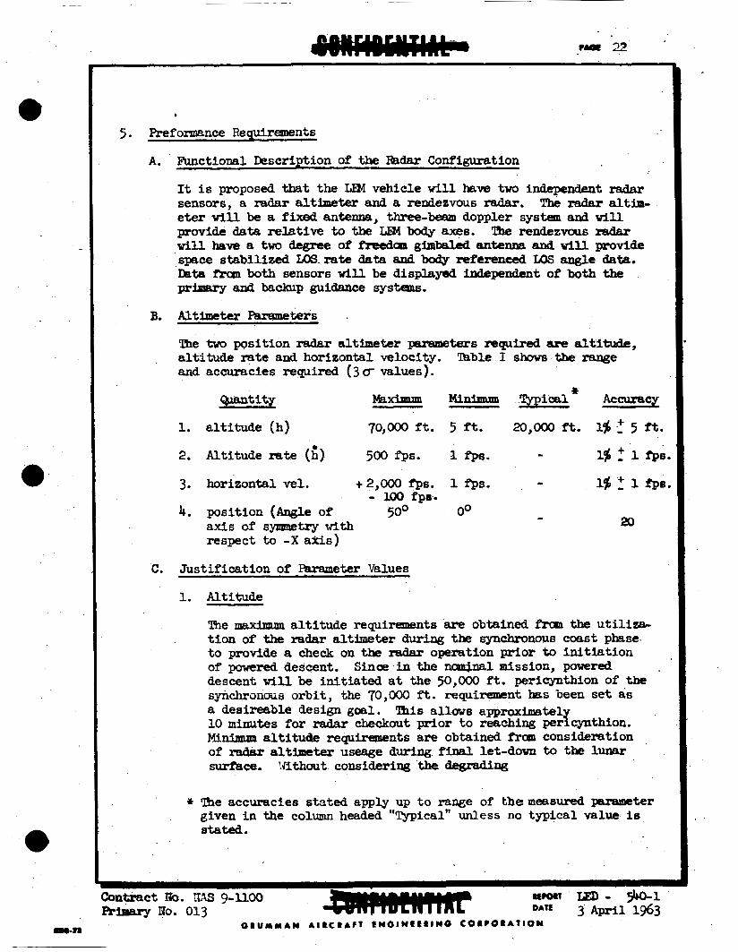
It i s proposed that the LIB! vehicle w i l l haw two independent radar sensors, a rsdar altimeter and a rendezvous radar. eter will be a fixed antenna, three-beam doppler system and will provide data relative t o the LEM body axes. The rendezvaus radar w i l l heve a two degree of M a n gimbaled antenna and will provide space ~tabilized LC)S.rate data and body referenced LOS angle data. hta f'ruu both sensors will be d i s p l a w ixidependent of both the prhuwy and backup guidance systens.
The Fadar altira-
B. JUtimeter Paresreters .
The two position radar altimeter psrameters rcquired are altitude, a l t i tude rste and horizontal velocity. a.nd accuracies required (3 u values).
'Jhble I shows the -e
QLBIltitX Minimrmr *
m i c a 1 Accuracy
1. a l t i t ude (h) 70,000 ft. 5 ft. 20,OOO ft. 16 5 it.
2. Altitude rate (h) 5 0 0 f p s . I f p a . - 15 : 1 f p s .
3. horizontal vel. +2,000 fps. 1 f p s . 15 : 1 rps.
4. position ( w e of - 100 fpa.
20 50° O0 - axis of synnmetry w i t h respect t o -X a*is)
C. Just i f icat ion of Parameter Values
1. Altitude
The maximum altitude requirements are obtained from the u t i l i za - t i on of the radar altimeter during the SynChrOnoUS coast phase t o provide a check on the radaF operation prior to i n i t i a t i o n of powered descent. descent will be in i t ia ted a t the 50,OOO f t . pericynthion of the synchronous orbi t , the 70,000 fi. requirement bas been set as a desireerble design goal. 10 m i n u t e s for radar checkout prior t o reaching pe r fwth ion . Mininnrm a l t i t ude requirements are obtained A.on consideration of radar altimeter useage during final l e t - d m to the lunar surfkce. !Jithaut considering the degrading
Since i n the ncu14nalmission, powered
This allows approximatel
* Ime accuracies s t a t e d apply up to range of themeesured parawter given i n the column headed l'Typical'l unless no typical value Is stated.

2.
3.
e f fec t of a dust cloud ra i sed from the lunar s u r f k e during the f i n a l moments before touchdown, a 5 ft. minimum a l t i t ude resolution should be obtained t o remain within ve r t i ca l im- pact attenuation capabi l i t i es of the landing gear. primary system colvputntion of a l t i t ude is updated j u s t p r ior t o final let-down, i n e r t i a l l y computed a l t i t ude will be ade- quate f o r landing.
If the
The alt imeter radar accuracy requirements have been examined i n the study of the use of the al t imeter radar during the final portion of powered descent. (Appendix 1 ) The 1% requirement on altitude accuracy represents a reasonable value fo r t h i s parameter and imposes no signif icant e r ro r i n the nominal descent t ra jectory.
Altitude Rate
Maximum a l t i t ude rate and m i n i m u m a l t i t ude rate requirements are obtained from u t i l i z a t i o n of the radar altimeter i n the powered descent and terminal let-down phases respectively. The values l i s t e d represent the l a rges t and the smallest values encountered during radar u t i l i za t ion from x),OOO f t . t o touchdown. The minimum value falls w e l l within the impact capabi l i t i es of the landing gear and represents a design goal fo r the sensor ra ther than the safe minimum value permissable f o r the landing gear.
The a l t i t ude r a t e accuracy requirement of l$ t 1 fps. i s designed t o provide suf f ic ien t ly accurate data f o r the ter- minal portion of the descent and let-down. The descent t r a - j e c t o r j i s suf f ic ien t ly sensit ive t o errors i n a l t i t ude rate t o require t h i s accuracy, par t icular ly i n the manual alter- nate mode o r when the i n e r t i a l portion of the primary guid- ance system has fa i led.
Hor i z o n a Velocity I .
The requirements fo r horizontal velocity data from the ra&r altimeter are obtained from the requirements of both the automatic and manual. a l te rna te mdes d w h g pvered descent as well as from the hover and let-down phase. range t o 2,000 fps. w i l l include the horizontal ve loc i t ies encountered below 20,OOO ft. a l t i t ude with the nor?.inal de- scent t ra jectory. 2,000 fps. i s a typical v a l x of V a t which the specified accuracy i s t o be attained. 5 , d fps. i s a desirable r a c e which would allow conplete checkout of a l l three beams of the radar prior t o i n i t i a t ion of powered descent.
A velocity
G R U M M A N A I R C R A F T E N G l H C C R l N G C O R P O R A T I O N c n e . n

The minimum requirement i s obtained from considerations of the landing gear capabili ty a t touchdown. horizontal velocity resolution insures a measurement capsbi l i ty W e l l within these limits.
A 1 fps.
While the three beam, Qppler radar i s re la t ive ly insensit ive t o altitude changes with respect t o the local ver t ica l , due t o the large change i n pitch or ientat ion of the LEM w i t h respect t o the lunar surface during the f inal portion of t he pwered descent, the radar alt imeter is required t o have two naniml operating positions w i t h respect t o thrust axis . Errars in antenna orientation primarily appear as velacity errors i n the horizontal and v e r t i c a l outputs and should be kept t o a minimum for the reasons discussed above.
D. Rendezvous Radar Parameters
'ihe rendezvous radar must be able t o provide the four parameters; range, rsnge rate, angle and angle rate. Table 2 shows the ranges and accuracies required (3dvalules).
Quantity Minimum Typical ++ Accuracy
1. Range (R) 400 N. M i . 5 ft. 30-0.2 n.m. (l$ f 5 f't.) 1.5% f 30 ft.
2. Range rate (R) ,f 4800 as. 1 f'ps xx)-Looo 1.05 5 1 fps. f p s
4. @le Rate * 15 mr./eec. 0 .2 mrlsec. - 0.2 mr/secand (Q)+
* Not required for Primary Guidance
E. Justificatioa of Pareraetem I 1. Range
%e noaximum range requirement on the rendezvous radar is obtained fran the u t i l i za t i an of tbe radar t o track the CSM i n its 80 N.M. orbi t from the lunar surface during the pre- launch phase of the mission. A m~urimtrm range of 400 n. miles is obtained when the CSM appears over the lunar horizon. Minimum ra.nge measuring capabili ty i s required durlng the docking phase. The 5 ft. minimum range represents a design goel since t h i s requirement must be finally established through docking simulation studies presently being carried out.
*+ h e footnote am for altimeter
O R U M Y A M A I R C R A f T C N O I N t f R I N O C O R P O R A T I O N
. The rendezvous radar accuracy requirements have been s tudied i n some detail fo r backup guidance (See Appendix 4 and 5 ) t o determine the AV penalties imposed by errors in the various radar parameters. The results of these studies in addition t o the requirements of the primary guidance system have served t o define the accuracies l i s t e d above. A range accuracy of 1.5s * 30 f t . represents a reasonable value based on the mid-course correction error studies. he 1s ?S 5 ft. accuracy is a design @;a that is desired i f it does not impose a significant penalty upon the radar design. ment the crew capabi l i t ies i n the docking mode. allows the use of the rendezvous radar as a backup t o the altimeter and as third a l t i t ude sensor to decide whether the IMJ or the altimeter are f'unctioning properly i n case of large discrepancy in the two outputs.
The increased accuracy I s desirable t o supple- It a lso
2. Rang e Rate
Maxirmrm and minimum range rate values are determined by u t i l i za t ion of the rendezvous radar i n the ascent and dock- ing phases of the mission respectively. Relative rates between the LEN and the CSM wil l -not exceed lo00 ms during ascent when it is desired t o t rack the CSM for e i the r monitor- ing or backup guidance measurements. tained during lunar surface tracking of the CSM but are not required f o r guidance computations. mldy f o r monitoring of the manual-visual docking phase and 1 fps. i s chosen to insure performance x i th in safe docking Impact velocit ies. The range r a t e accuracy requirement is based upon the study r e su l t s discussed above.
Higher rates are ob-
Minimum rates are u t i l i zed
3. Angle
The minimwn gimbal freedom of the rendezvous radar is chosen t o insure the LEM of orientation f l e x i b i l i t y s o as t o pennit visual mbnitoring and/or thrusting capabili ty during the rendezvous phase and landing with a beacon. i s a l so required for tracking of the C S M m e the LEM is on the lunar surface. have a l s o been obtained from studies of "mid-course"correction e r ror penalties for both primary and back-up guidance schemes. The 15 mr. bias uncertainty represents a s t a t i c e r ror require- ment over the period of the mid-course and rendezvous phase. The 3 mr. randcxn uncertainty represents the maximum allovable
Gimbal freedom
Angular position accuracy requirements
G R U M M A N A I R C R A F T E N G I N E C R I N O C O R P O R A T I O N

value of short period variations i n boresight accuracy to: a) a t t a i n the required measurement accuracy f o r midcourse correction if a non-homing rendezvous is used and b) t o achieve the required Lo6 rate accuracy or the homing rendez- vous.
4. An& e Rate
The maximum and mlnirmun a-ar rates are obtained frm the u t i l i z a t i o n of the rendezvous radar during the terminal ,rendezvous phase t o measure line-of-sight r a t e t o the CSM. The maxixium and minimum values are obtained f!km the c o n s i b e ra t ion of rendezvous from off-nomina3 t r a j ec to r i e s studied i n Appendix 5 ra te sccurzcy during some of the off-nominal t r a j ec to r i e s and t o insure a successful rendezvous, the angle rate measurement accuracy must be within 0.2 mr/sec.
. In order t o measure the minimum line-of-sight
5. Antenna G i m b a l Limits
A prelininary definition of the antenna jimbal axis orientation relative to UiM body axe8 and of the required angular freedom about these gimbal QXCS le shorn in Figure 1. The drnbal limits prcaented are based on an analysis of possible trackin,: radar utilization during aU mission phaeee as discusrred in Section 3. The &bal axis order and orientation are derl&~ed to be t he same (LO
thoac of the O W , in order to pemlt d1;ital readout of both CUU and radar poeition with a coIBLon seL of di:ital ahaf t transduce re.

The mor conclusions derived from the studr of the performance requirement8 of non-inertial sensors vith respect to t h e Lgl( misrion 8re summarized below:
b . The primary u t i l i za t ion of no-inertial renaorr occur8 during 0) the terminal portion of the powered dement phase and b) d u r i w ascent cOObt and rendasvow.
These senmra are a l r o u s e m during a) t h e touting dercent,for t raJectom verif icat ion, b) stay on t h e lunar iurface, for determination of C8n orbit, c) abort, t o pruvide a non-inertial attitude reference md d) during powered descent tourrdr 8 surf8ce beacon, f o r proriding LOB guidance data.
Duriw normal povered descent, a l t i t u d e ami velocity measurements are used for I W updetinp5.
Studier of the e f fec t of t e r r a i n .lopes on the effective- near of a l t i t ude updating of t h e IMJ indicates that
8) for reasonable eloper (up to about 60) altitude updoting can achieve rucceaaful landings.
b) i n i t i a l altitude o f f r e t s ud raoonable m e s u u e - ment errors Vi11 not compnwirc the a b i l i t y t o lmld Mfe1.Y.
d) s l an t w i n g t o the l8nding point is required only for beacon guided descents or under conditions of very severe ter-n nlopes (15O).
Durint: coooting ascent, non-inertial measurementr U o w the performance of mid-coume correct ion8,md reduce the AV penalty for rendezvous-
* Mid-courae correction s tudies indicate that
8j a simple correction regime can reduce the AV penalty t o ramonable l eve l s even i n the prerence of l u g e povered -cent b w o u t errors.
b) comporativelv large meaourement error. can be t o l e n t e d durind mid-caurrc, rime even v i t h Urge miss distances ( 5 NOM.) a homing nndezvour can be performed economically.

Rendezvous study resu l t s indicate t h a t
manual operation of the homing rendezvous is feasible i f t h e range ra te is reduced ; r a d u a l l v and a t t i t ude constraints f o r v i s i b i l i t y are impoeed.
range r a t e should be a function of range.
t h e thrust sequence f o r rendezvous should be performed by thrustiw i n separate or tho~onal maneuvers to reduce rpnde rate and M)B rate.
since the stepwise reduction of r-e rate alters even a perfect intercept trajectory, Lo8 rate null must be maintained t o assure rendezvous.
the AV bud& f o r the terminal homin,: phase is Q function of the errors exis t in& at rendezvous in i t ia t ion .
t h e AV penalLy for adapting the n o m i d rendezvour maneuver to mual operation is n e g l i ~ i b l e .
i n General, 20 N.W. is nearly the optimum distance for homin;: rendezvous i n i t i a t i o n for a l l t rqlector iee which are reasonably close t o the nominal
the x-axis impulses applied d u r i w t h e homing rendezvous approach or 20 Sclov the estimated minimum impulse capabili ty of the main ascent engine so tha t the RCS should be u t i l i z e d f o r t h i s phase
As a result of the s tudies described and of t h e conclusions summarized above, the f o l l o w i q reconnnendations ore made:
A radar system shodd be provided t o furnish t h e non- i n e r t i a l measurements required i n the various mission phases
Tvo separate radars should be supplied - one f o r deter- mination of a l t i tude and velocity re la t ive t o t h e lunar surface, and one fo r trackin4 of the CSM and/or a surface beacon.
The trackin,: radar should be implemented to be capable of backin, up the alt imeter and to provide the m e a n s of decidin; betweer the altimeter and DIU .if they provide si&ficant lv different indications of position or veloci t y .
G R U M Y A N A I R C R A F T C N G I N L f R I N G C O R P O R A I I O N
Data from these radars should be such a8 t o be meanindul and useful t o the crew i f d isp layed direct ly . The trackin,: radar antenna should be mechanically glmboled i n a two-degree-of-freedm confibpration t o provide t h e orientation f l e x i b i l i t y required for u t i l i za t ion i n a l l those mission phaeeo in which trackin& data is uti l ized.
RPdor drta display should be provided to U O W =- imum utilizcrtion of crew capabili t ieo i n performing the landin:: and rendezvous p-es.
Automatic modes of landing and rendezvous ehould be designed t o be cmpat ible with manual e l ternate or mpnuQl back-up modes i n the sense of allowing ef f ic ien t end successful completion of t h e m e u v e r i n the event of f a i lu re of the automatic rJ. & G. tavstun.
Contract h. #As g-uoo PrimPr.; No. 013
G R U M M A W A I R C R A f T L N G l N L t R l N O C O R ~ O R A T I O N

n 3 d t- U d
5
&-- I
Appendix 1
Ut i l iza t ion of Altimeter Data During
Terminal Axt ion of Powcrcd Descent
Purpose - It is the purpose of t h i s analysis t o study the u t i l i z a t i o n of
a radar altimeter i n conjunction w i t h the I S f IMU and AGC t o generate
the navigational information required during the f ina l 20 I@! of
descent - w i t h termination at an a l t i t u d e of lo00 ft. above t h e lunar
surface.
is not impossible t o correct t h e i n e r t i a l l y computed LEld posi t ion
Since radar data provides essent ia l ly relative i n f o m a t i o n , l t
on the basis of radar altimeter data unleos the loca l surface is
accurately known. For t h i s study, radar altimeter information was
used t o deternine thes lope o f t h e lunar surface and, w i t h t h i s infor-
mation, t o predict t h e coordinates of the desired target (hover
point) .
parameters: radar a l t i t u d e errors, i n i t i a l v e r t i c a l posi t ion and
ve loc i ty e r rors i n t h e IEN and AGC variat ions i n target a l t i t u d e and
This study considered t h e terminal e f f ec t s of t h e following
various surface slopes.
Procedure - The f i n a l descent motion was considered t o be planar.
analysis, t h e was treated 8s a point mass. The aystem was
analyzed and a powered f l ight simulation vas performed on the
IBM 7094.
For t h i s
The simulation provided t h e following:
G R U M M A N A I R C R A F T E N G l N t t R l N G C O R P O R A T I O N imc.7s

1. Lea Motion - The actual trajectory flown by the LBa was determined
by solution of the two-degrees-of-freedom-equations of
translational motion for a point mass.
2. Im - - The inertial rneasurenient unit consisted of two integrat-
ing accelerometers orthogonally mounted on a gyro-stablized
element.
of incremental velocity changes.
The outputs of the accelerometers were in the form
The platform was aligned
so that at the start of the final descent one accelerometer
was oriented along the local vertical, while the other
accelerometer was oriented along the local horizontal.
3. Radar Altimeter - The altimeter was mounted such that it was always
directed downward along the local vertical.
(position) information was utilized for the AGC navigation
computations .
The altitude
4. Lunar Hodel - The nominal lunar surface vas considered to be the
boundary of a uniformly denee spherical moon.
surfaces were linear ( i -e . , infinite radius of curvature),
where the magnitude of the slope was detenined by the angle
between the inclined surface and the local horizontal at
The eloped
the target (see Figure Al-l)*
defined by the followin,r convention:
indicated that the luniir surface was decreasing In altitude
The sil,;n of the slope vas
A positive slope
Contract No. NAS g - l l O O Primary No. 013
Q R U M M A N A I R C R A F T L N C I N L L R I N C C O R P O R A l I O N

as the LEN traveicd toward the target .
5* Guidance L a w - The guidance l a w used f o r t h i s analysis is based on the
"Line of Si&it" (LOS) proportional navigation technique devtl-
oped by L.S. Cicolani, kues Research Center, and presented i n
K4SA TIV-D-722.
simulation is the same as t h a t described i n GAEC Study Report
PDM-33-88.
and the angle betveen the veloci ty vector and the l ine-of-sight
t o determine t h r u s t magnitude and di rec t ion (pi tch a t t i t ude )
cormuands. For the purpose of t h i s analysis, t he two required
gains i n the equation were f ixed f o r a l l the sirnulated tra-
Jector ies .
t h rus t vector which does not follow the cammands closely, but
does not optimize the t ra jec tory w i t h respect t o AV.
The form of t h e equations programmed f o r the
This guidance l a w u t i l i z e s s l an t ran,;e information
This combination of gains appears t o produce a
6. Thrust Vector Controller - The thrust vector comands a r i s ing from the LOS proportional
navigation guidance law were instantaneously transformed i n t o
engine t h r u s t s and pitch a t t i tude . No provision &is made f o r
response lags.
rnaxiruuri~ thrust of lG,5W lba. mid a E:l t h ro t t l i i i t r a t i o was
A single th ro t t l eab le descent engine with
s irnulat ecl . AGC - 7 - -
The function of t h e AGC i s t o read the output of the
accelerometers and transform t h i s information in to current
posi t ion and velocity inforpation. It a l s o processes t h e
ContrEict No. WS 3-11Oc) Prhar'y No. 313
G R U M M A N A I R C R A f l C N C l N f L R l N G C O R P O R A T I O N f N C . 7 3

Contract No. Np.S 4)-lluCJ Yri:sary No. dl3
radar infonaat ion and predicts the posit ion of the ta rge t by
a l i n e a r (two poinl) extrapolation technique. It processes
the present i n e r t i a l measurements bud the t a rge t information
t o obtain t h e necessary inputs f o r the guidance l a w . Lastly,
it implements the guidance l a w and issues the indicated thrus t
commands.
computer ra te , which f o r t h i s anelysis i s at 2 'cyc les per
second.
All of these functions arc performed at t h e same
The functional relationships between each of the above
components can be seen i n Figure A1-2.
8. Cutoff Cr i t e r i a - Idealiy, it vas desired t o terminate the t ra jec tory at
an a l t i t u d e of 1000 f t . above the lunar surface, w i t h a zero
t o t a l velocity. However, t he par t icu lar guidance l a w t h a t was
u t i l i zed i n t h i s analysis does not provide uniform convergence
of t h e posi t ion and velocity components.
convergence is most notable i n the veloci ty components-
ffiission safety, and f o r need of a common reference, the radial
veloci ty component was used t o test f o r termination. The AGC
computed value of radial velocity was used for cutoff rather
than t he ac tua l velocity, t o simulate the e f fec t of automatic
The lack of uniform
For
operat ion.
A t the start of a typical t ra jec tory the i s deecendlng
rapidly. As the LEM approaches the ta rge t , the downward velocity
decreases inonotonically. fIowever, depending on several Gidance
ENC ?3 C R U M M A N A I R C R A f l t N G l N E L R l N G C O R P O R A T I O N

parameters, when t h e UM is within a short distance of t h e
target (say, l e s s than 100 f e e t ) the downward veloci ty may
suddenlr start t o increase again. Thus, two tests were used
f o r termination: t h e f irst tes ted t h e AGC computed radial
velocity, ;, t o see whether it had passed through zero; the
second, tes ted t h e two most recent values of t o see whether
t h e y were monotomially decreasing. If e i the r test indicated
that a termination condition had been exceeded, a "forced-halfing"
subroutine was used t o backtrack and loca te t h e c losest point
t o the termination point.
Assumptions - The following assumptions were used thmu&hout the analysis:
The IMU was last aligned 30 minutes before i n i t i a t i o n
of Ixrs navigation.
1.
2. A l l IMU and AGC errors which have accrued since the
last alignment appear only i n the acceleraaeter loop
which is ve r t i ca l a t i n i t i a t i o n of LOS navigation.
3. I n i t i a l conditions f o r t h e f i n a l descent are determined
by t h e f i n a l conditions of an op t imu AV guided t raJectory
s t a r t i n g a t pericynthion of 50,003 f t . These i n i t i a l
conditions are:
I n i t i a l LEM a l t i t ude above spherical lunar surface = 18,828.8 It,
I n i t i a l control awle = 0.0 degreea
I n L t i a l radial velocity = -24d.68 f t . /sec
- C R U M M A N A I n C R A I T E N G I N E E R I N G C O R P O R A T I O N

0
I n i t i a l t w c n t i a l velocity = 2140.68 f t / 8 e C
Central angle of target = 1.1880 deg.
Specific impules of descent engine = 3lO.O 8-0
I n i t i a l mass of LlW 455.44 6lUgS
4. The radar yields t rue v e r t i c a l a l t i t u d e information
t o within the radar accuracy. The radar accuracy is
defined as a percentage of the altitude or by E con-
s tan t "stand-off", whichever is greater.
Parameters Studied - The following independent parameter8 were investigated.
1. Lunar Surface - The lunar surface -8 defined by
two parameters: t a rge t a l t i t ude above the epherical
moon, end the slope of the eurface measured with
respect to the local horizontal at the target.
the case where a slope change vas simulated, the
In
first inc l ine was defined as previously described,
while the second inc l ine had a slope equal t o the
negative of the first elope.
S u r f ~ c e a l t i t udes beneath the Target altitude6
above the spherical noon VCM varied from -4OOO ft-
t o +WOO ft., while surfwe slopes of 2 3 degrees
were considered.
R L K W t LED-540-1 OATC 3 April 1963
Contract No. NAS 9-llOO Rlrary Eo. 013

2. IMJ Errors - Pre-LlgM studies indicated tha t t h e most
c r i t i c a l sources of e r ror f o r LO8 guidance arise from
er rors In the ve r t i ca l channel of t h e IMU and AGC.
Thus, i n i t i a l ve r t i ca l posit ion e r rors rangin;: between
-5OOO f t . and +5OOO f t . were investigated. It vas
assumed that these e r rors vere the result of integrating
veloci ty errors. Further, it was assumed tha t these
veloci ty e r rors were constant since the last Iwu alignment.
Since the last alignment occured 30 minutes ear l ie r ,
t h e ve r t i ca l velocity error, Be,, correspondiw t o an 0
e r ro r i n ve r t i ca l position, Se,, can be determined by
t h e relationship
Therefore, the range of i n i t i a l ve r t i ca l velocity
errors correspondind to the aforementioned i n i t i a l v e r t i c a l
poeit ion e r rors I s -2.78 ft./sec. t o 42-70 ft./scc.
3. Raatlr Error8 - Since the target is 1000 feet above the
lunar s u r f k c , radar "stand-off'' e r rors were neglected.
Therefore, the only radar errors considered are those tha t . '
are proportional t o a l t i t ude - the range of t h e proportion-
a l i t y constant considered was between -1.58 t o +l.5$.
Outputs
The following cut-off o r hover parmeters were studied:
1. The f i n a l ve r t i ca l velocity - This should be near ly eer-
Contract No. BAS 3-1100 Primary Roo 013

2.
3.
4.
f o r the ideal case. However, various error sources
cause errors i n the v e r t i c a l veloci ty computation.
Thus, vhen the Dcu indicates a nearly nulled ver t ica l
velocity, t h e actual v e r t i c a l veloci ty can be qu i t e
Large. This nactual" veloci ty is the veloci ty plotted.
The final tangent ia l velocity - Because of the non-uniform
convergence of the state parameters, the tangent ia l veloci ty
does not approach %em as rapidly aa the radial velocity.
Thus, f o r the nominal t ra jec tory (zero component e r ro r
sources), although the f ina l v e r t i c a l ve loc i ty is less
than 0.01 ft./sec.jthe tangent ia l veloci ty is still
6.33 f t ./see.
- AV - TheAV plot ted in the graphs is the sum of theAV
used during the LO6 navigation phase
veloci ty remaining at cutoff.
p lus the tangent ia l
Position - "ne posit ion referred t o in the appended figures
is the actual slant-range distance betveen the
t h e t a rge t at cutoff
and
Following is a summary of t h o data displayed i n Figures AI.-3 - Al-15.
Figure A l - 3 illustrates the t ra jec tory of the Lgw assuming no
errors in the IW-AGC or i n the radar.
LBD-w-1 D A R 3 April 1963
C a n t r a c t Ilo. RAS 9-UW Primary #o. 013
G R U M Y A N A I R C I A I T E N O I N L E R I N O C O R P O R A T I O N

Fiwn A1-4 i l l u s t r a t e s the e f f ec t s of a 5 W f t . i n i t i a l error
i n t h e coniputed ve r t i ca l position.
is essent ia l ly ident ica l t o tha t in figure A1-3.
The actual t ra jec tory flown
Figures Al-5 and Al-6 are p l o t s of the cutoff paremetere VS.
i n i t i a l e r ro r in the computer v e r t i c a l velocity, w i t h the radar
e r r o r s 1.5% and 0.58 respectively.
FigUlY N-1 i l l u s t r a t e s t h c A V penalty VS. i n i t i a l e r ro r in tho
computed v e r t i c a l velocity.
case of f igure Al-5, the lower p lo t t o t h e case of figuae U - 6 .
The upper p lo t corresponds t o t h e
Figures ~ 1 - 8 and A1-9 are p l o t s of cutoff parameters VS. posi t ive
and neGative radar errors. The surface configuration and in i t ia l
v e r t i c a l e r rors are l i s t e d on the graph.
Figure A 1 - 1 0 is a plo t of cutoff pararneters VS. negative radar
e r ro r s where the i n i t i a l v e r t i c a l errors are the negative of those
used fo r figures Al-8 and Al-9.
Figure A l - 1 1 i l l u s t r a t e s theAV penalty VEI. radar errors , the
upper middle, and lower jraphs correspond t o the conditions of
f i9 re s a-8, A1-9 and A1-10 respectively.
Figure A1-12 shows cutoff pararneters vs. a l t i t u d e of t a rge t above
the spherical moon.
Fiefure Al-13 illustrates AV penalty vs. t a rge t a l t i tude .
Figure Al-14 represents the t ra jec tory flown by M when it
t raverses a surface which has a change in slope.
Ptht NO. s 9-1100 imary 100. 0 4" 3
GRUMMAW A I R C R A F T E N G I N E E R I N G C O R P O R A T I O N
pigum Al-12 i a B tabulation of the cutoff velocity p.rruratcrs
aa the tinat at which the eecond slope I 8 introduced I 8 varied.

f'rGURE /!/-I GEOMETRY AND NOMENCLATURE
C o n t r a c t No. NkS 9-1100 ?rim.ary No. 313
Resort LED-5b0-1 3 n p r l l 1963

LEN'
G UI DANCE LAW
t COMPUTE VELOCITY CHANGE DUE TO THRUST
ACCELERATION
li,
I M U Sh'SES VELOCITY CHAM$€ DUE TO
THRUST ACCELERATION r

Nomenclature
A. Symbols
a l t i t ude of actual moon surface above t h e average surface
the angle of slope of the moon's surface
computational parameter required t o determine t h e surface incl ine error i n incremental velocity due t o Z-accelerometer bias error acceleration due t o lunar gravity along Z-axis gravitational constant f o r moon
a l t i t ude above actual lunar surface altitude above average surface er ror i n H radar altimeter accuracy parameters to be read as an accuracy of tl005 ($) or tk ( f t ) , whlchwer is greater.
radar altimeter rate accuracy parameters t o be resd as an accuracy of 900% ($) or tk4 ( f t ) , whichever i s greater
i n e r t i a l polar coordinates, where y is measured posit ive clockwise from Z-axis. radius of spherical moon linear renge-to-go along lunar surface
time
2
IC-1 t - t K
tn - tn-l thrust magnitude and orientation angle i n e r t i a l rectangular Cartesian coordinates with origin a t moon's center and Z-axis along position vector t o IBf at t i m e t - 0 coordinates i n XZ plane incrementsl velocity due t o thrust
Contract No. NAS 9-ll00 I t C O R l LED-540-1 primary No. 013 DAW 3 April 1963
G R U M M A N A I I C R A f l C N G l N t f R l N G C O I I O R A T I O N

C. Notation
- (. 1 -
actual value
with respect to ground (lunar sur,&ce) integration rate of equations of motion measured value
corrected measured value
integration rate of IMU loop sensed value w i t h respect to the target
d dt -
Contract No. NAS 9-1100 primary NO. 013 DATE 3 AWU 1963
lEPOn1 m-540-1
C a l J M M A N A I l C l A F l ' C N G I N C L l I N O C O l P O l A l l O N ENQ-I8

Contract No. WIS 9-1100 Primary XO. 013
Report IED-S&O-l 3 April 1963


Cmtract No. NAS 9-1100 Prhary No. 013
&port L w - 5 L O - 1 3 A p r i l 1963
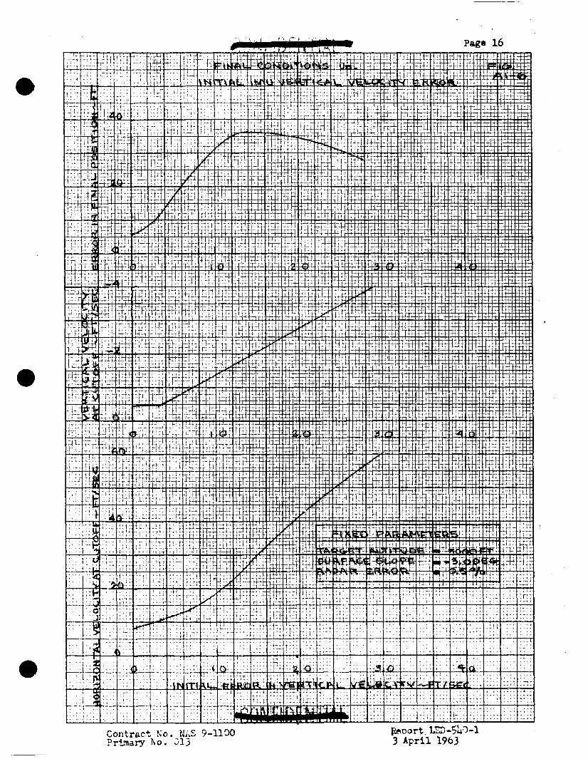

. L . Pam 17
ContI-act Ao. NAS 9-1190 Primary No. 013

Contract No. BhS 7-ll'X ?rirnary 30. 013
RePo rt L'~-%0-1 3 April 1963


Coct rac t No. NAS 9-1133 Primary No. 013

Contract Yo. SA'-: 9-1100 Prlinary No. 913

.
Contract No. NAS 9-1100 +@&/g&& - Primary No. 013 2 ,
Re art LED- Lo-1 3 PP rll 196 3


Page 24
Contract No. WAS 9-1100 Prinsarg No. 013
€&port LED-SLO-1 3 April 1963

Primary No. 013 3 A p r i l 1963 ~~ ~~

Page 26
Contract 100. HAS 9-UOO Primary No. 013
bport LD)-SbO-l 3 April 1963

0
0
I
I
0
I
I
I
I
I 1 I
I
I
I 1
1 ,

*
M Page 28.

Page 29
Ccntrant No. NXS 9-l.lW Primary No. 01-3
I 1. I . ..A- - 4 L--.
I 2

Contract lo. NAS 9-ll'x) Primary Ro . 213 Report LED-5b3-1
3 April 1963

. -
Appendix 2
Effect of Ascent Inject ion Eh-rors and Time of Correction onAV Requirements f o r Midcourse Correction
-pose:
The purpose of t h i s study w a s t o determine the e f f ec t of ascent
in jec t ion e r ro r s on the t o t a l 4 V requirement f o r rendezvous when
using a midcourse correction technique.
Procedures and hswupt ions :
It was assumed that a perfect inject ion would result i n a Hohmann Transfer orbi t starrting at an a l t i t ude of 50,000 f t . and ending at an apocynthion of 80 N. M i . The t o t a l time o f flight
for t h i s t ransfer is 3470 seconds.
For the purpose of t h i s study, initial ascent in jec t ion errors w e r e propagated t o posit ion and velocity e r ro r s a t the time of mid-
course correction. From these off-nominal conditions, t h e 4 V required
f o r midcourse correction w a s determined. " k & V correction maintained
a constant t o t a l time of flight, which for the assumed Hohma,nn equals
approximately 3470 seconds. The next step w a 8 a calculat ion of the
AV required at ~ intercept t o ga i n to a c i rcu lar orbit. This impulse w a s nominally added t o theAV midcourse impulse t o obtain the total. AV requlred.
The e r r o r propagation equetions were based on a perfect ly c i r -
cular orbit of the CSM, and on a lunar expansion of gravi ty i n the v i c in i ty of' t he CSM. In addition, the equations assmed a po in t mass and a lunar transfer orb i t .
Range of Passnreters: The indection e r rors were related t o a CSM centered coordinate
system defined as follows: +G , *L'c,
LGPl L O C A L +cs, +vcs VECl-rKAL
O I U M M A N A I I C R A l T I N O I N C I I I N O C O I C O I A T I O N
CRS-lS
TWO sets of inject ion errors were considered. They were obtained by assuming a pre-programed pitch program and 1% and a 3$ off- nominal thrust. When 1% excess t h r u s t w a s considered, the injection
errors mre:
c1 = 6,804 f t .
C3 = 3,178 f t ,
CL = 20,413 ft,
c, = 9,533 ft. 3
vel = 10.5 fp.
VC = 13.1 fps. 3
QCl = 31.4 fps.
vc = 3 9 . 4 f p s . 3
The results are presented i n Figures A 2 - 1 - A2-4. Figures A 2 - 1
& A2-2.represent the AV required for midcourse correction f o r the
14 and 3% cases, respectively, versus time of midcourse correction. The times of midcourse correction were a l l consid,ered re la t ive t o engine burnout.
Figures A2-3 & A2-4 represent the t o t a l & required for the
1s and 3$ cases, res,pectively, versus the time of the midcourse correction.
Contract No. NAS 9-Uoo primary No. 013 3 A p r i l 1963
REPORT LED-540-1 ~ - -
O R U M M A N A I R C R A P T E N G I N L C R I N O C O R P O R A T I O N

C P


1
t
0
t a C P I

~-
Ff.1- Code No. 013 GRUMMAN AIRCRAFT ENGINEERING CORPORATION

0
0
-0
Appendix 3
Effect of Single Point R a d a s Measurement Ekrors On Accuracy of Midcourse Corrections
W p s e : U s i n g radar data, Ll34 posit ion and velocity r e l a t ive t o the
CSM can be determined from a s ingle point measurement of range, range ra t e , angle and q l e rate. Using navigation data, course
corrections can be made t o intercept the CSM. The pwpose of t h i s
study is t o determine the e f f ec t of the radar measurement errm on the t ra jec tory errors .
A-ocedures and Assumptions:
Four r a d a r measurements (range, range rate, aagle and -le r a t e ) at a single point on the t ra jec tory were considered. A Hohmar-m t ransfer o rb i t frm 50,000 f e e t t o an a l t i t u d e of 80 N. M i . was
used t o determine nolllinal values of range, range rate, angle and
angulss r a t e , and therefore numerical values of radar errors .
Each radar measurement e r ror was considered separately (statistically independent ) and resolved in to a CSM-centered coordinate system
(see Figure A3-1). Final ly each er ror was propagated t o the treJec- t o ry point of in te res t . RSS cmputation wa8 then made t o describe
the t o t a l e f f ec t of all the radar errors .
Figure A3-1
&O)EIAR SURFACE
"he e r ro r propagation equations were based on a perfectly
circula;r o rb i t of the CSM, and on a l inear expansion of gravity
i n the v ic in i ty of the CSM. I n addition, the equations assumed
Contract No. IUS 9-llOO prinesy rso. 013
REPORT m-540-1 DATE 3 A p r i l 1963
E I C - 7 S G I U M M A N A I R C R A f T C N O I N L C I I N O C O I C O I A T I O N

Table A3-3 is a comparison of the RSS e r ro r s usin@; a radar w i t h 4 = I X ~ O - ~ rad/sec. or = L ~ O - ~ rad/sec
Table A3-4 is a l i s t i n g of i n i t i a l r a d a r measurement e r rors
resolved in to CSEI coordinates..
% m

RSS OF THE PROPAGATED ERRORS
For A l l Cases Considered & = 0.0001 nsd/sec
Radar Errors Propagation Interval -l!Fzaii----r-
C 3 W 1
5,402
133,697
-_I -- ..-
29,572
10,374
135,219
29,707
5,430
133,704
29,573
10,388
135,225
29,708
9,'T79
135,123
29,575
50.2 49.0
185 7
32.6
50.2
188.1
33.0
After 1 Apocynthion Burnout i 97.5
1 30 n.mi. I Apocynthion 1
bkd. 3% 34.2
51.0 _ _ ~ --
625 secsf 30 n.mi. t 83,326
41,554
4,269
97.5 Wunout 30 n.mi. 1 Apocynthion
625 s q - 30 n.mi. --. __--.
34.3
49.0
185.7
32.7
83,279
18,561
2,046
83,226
41,602
4,272
83,511 _II_
2,414
50.2
97.5
34.2
51.1
97.5
34*3
625 sec 30 n.mi. 50.2
188.1
33.0
After Apocynthion Burnout I W Q . 0 0 6 rsd 49.8
187.8
32.7
50.7
97.6
34.2
Aczut I Apocynthion hR=O. 05%
&=a. 34
83,557
54,787
4,460
13,193
136,629
29,710
50.9
190.2
33.0
51. 5
97.7
34.3
After Burnout Apocynthion
30 n.mi. 1 Apocynthion 625 secs I 30 n.xni. 83,511
40,241
2 , 421
49.8
187.8
32.7
50.7
97.6
34.2
9,795
135,129
29,576
I Apocynthion Burnout
30 n.mi. 1 Apocynthion 51.0
190.2
33.0 - REPORT
13,205
136,635
29,711 - 83,557
54,823
4,464
zLt 1 Apocynthion 30 n.mi. 1 Apocynthion
DATE 3 A p r i l 1963 C R U M M A N A I R C R A f l E N G I N E E R I N G C O R P O R A T I O N
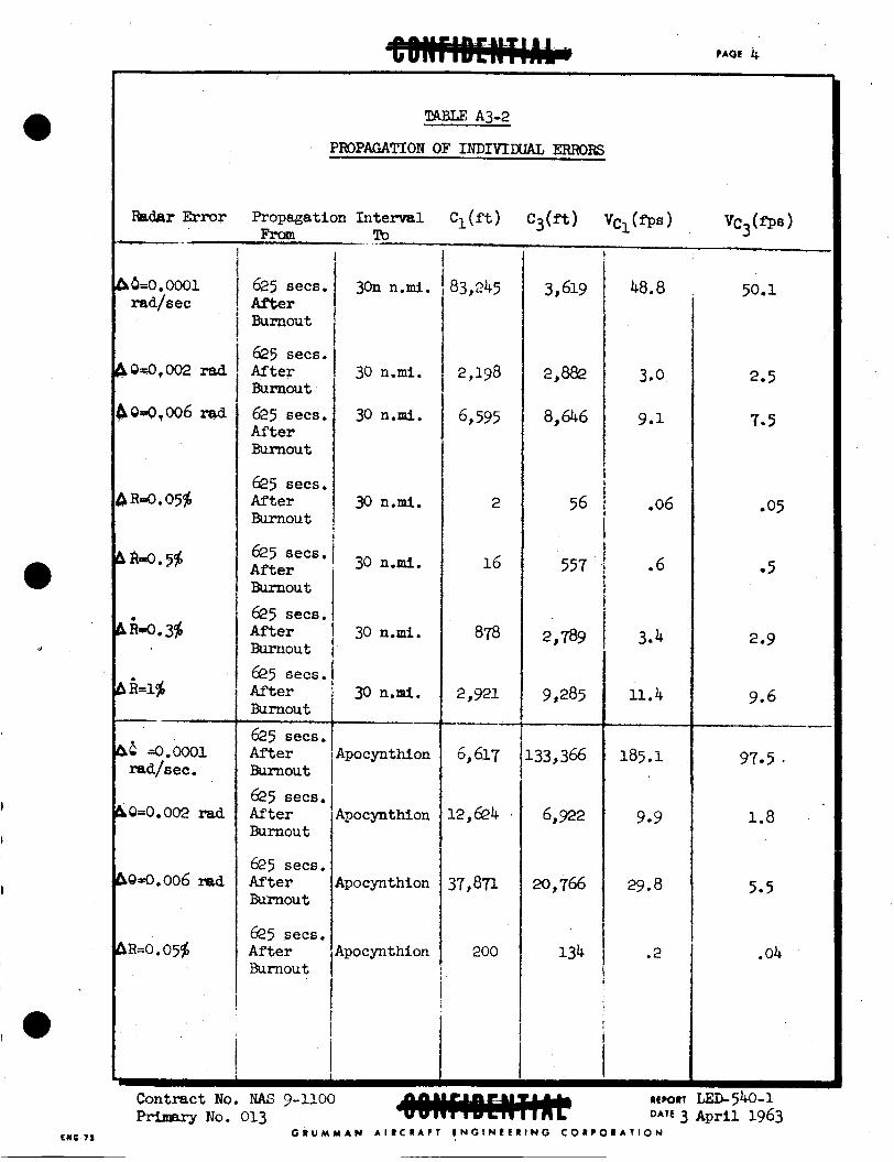
Radar Error
CI L o 0001 r4d/sec
b :LO. 3s
b i = l g -
$0-0.002 rad
bQ4.006 rsd
hR=O .05$
'CABLE: A3-2
PROPAGATION OF INDIVIWAL ERRORS
Propagation Interval C l ( f t ) ~ 3 ( f t ) V~,(OS) vc3(fPf3 1 Awn -. To .
625 secs. After Burnout
625 secs. After Burnout 625 sees. After Burnout
625 sees. After Wunout
625 sees.
625 secs.
After wupou t
After Bunout 625 secs. Af'ter Burnout 625 secs. A f t e r Burnout
After Burnout
6 2 5 sec6. After wrrnou t
625 secs,
625 secs. A f t e r Burnout
3on n.mi.
30 n.mi.
30 n.mi.
30 n.mi.
30 n.mi.
30 n.mi.
30 n.mi. --
tpo cynthion
gocyn thion
qocyn thion
.Po c y n t hion
3,619
2,m
8,646
56
557
2,789
9,285
.33,3&
6,922
20 , 766
134
48.8
3.0
9.1
.06
.6
3.4
11.4
185.1
9.9
29.8
.2
97.5 *
1.8
5.5
.04
Contract No. NAS 9-1100 NO. 013
C R U M M A N A I R C R A F T F N G I N E € R I N G C O R P O R A T I O N
REPORT LED- 540-1 3 A p r i l 1963

CAOE 5
-.
Radar Error Propagation Interval - . -EhL m
625 .ecs.I After Apocynthion Burnout 625 secs. After Apocynthion Blrnout
625 secs After Apocynthion Burnout
0
30 n.mi. Apocynthion
30 n.ml. Apocynthion
30 n . a . I Apocynthion
1 f
30 n.mi. Apocynthion
30 n.mi. Apocynthion
30 n.mi. I Apocynthion I
C1 ( f t 1
1,999
11,720
39,033
1,598
457
1,372
18.4
184
1,180
3,932
c3(ft)
1,338
6,368
21,210
29,558
151
454
29.5
295
8%
2,9Q
Contqwt No. mAs 9-ll00 Primary Bo. 013
32.6
02
05
. 04
.4
1.4
4.8
0.4
1.0
3-2
34.2
01
.3
0 0 2
02
e 3
1.0
G R U M M A N A I R C R A F T E N O I N E E R I N O C O R P O R A T I O N
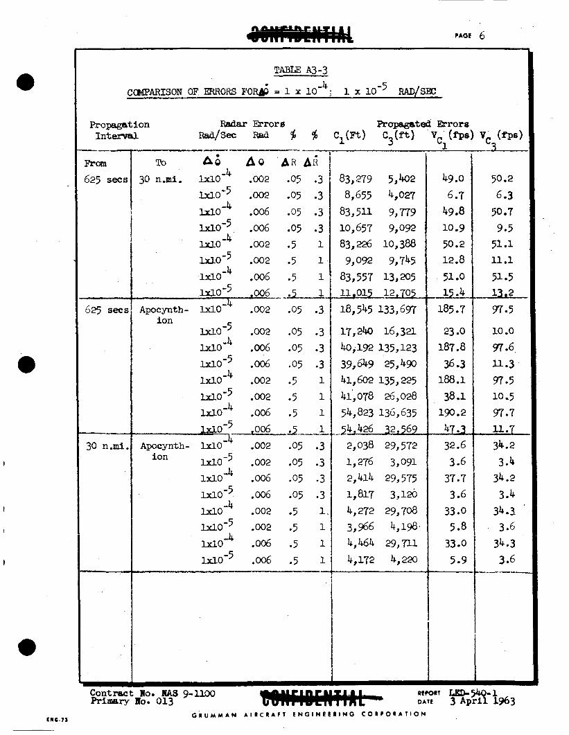
PAOE 6
I A O - ~ .002 .05 .3
M O - 5 .006 .05 .3 lr1~-4 -006 -05 .3
1x10⁻⁵ .002 .5 1 M~ -4 .oo2 .5 1
I
8,655 4,027 83,511 9,779 10,657 9,092 83,226 10,388
9,092 9,745
t
Apocynth- W O - 4 .002 .05 .3
b d O - 5 .002 .05 .3 = o - ~ .006 .05 .3
Ion
M-3
18,545 133,697
17,240 16,32l
40,192 135,123
-4 COMPARISON OF ERRORS FO& = 1 x i o 1 x 10⁻⁵ RAD/SBC
U O - 5 .006 .05 .3 U O - ~ ,002 .5 1 rx10’5 .002 .5 1 M O - ~ .006 .5 1
W O ’ 5 ,006 2 1 Apocynth- lx l0 .002 .05 .3
U O - 5 .002 .05 .3 lXl0 Ir .006 .05 .3 W O S 5 .006 .05 .3 w0-4 .002 .5 1,
2-- ion
WO-5 ,002 .5 1
--- From
625 secs
39,649 25,490 41,602 135,225 41,078 26,028
54,823 136,635 ,_-$,426 32,569
2,038 29,572 1,276 3,091 2,414 29,575 1,817 3,126 4,272 29,708 3,966 4,198
625 SeCE
- 30 n.mi,
49 .O 6.7
49.8 10.9 50.2 12.8
51 .O
185 -7
23 .O
&.
187.8 36 -3 188.1
38.1 190.2
47.3 32.6 3 -6
37.7 3 06
33 00 5 08
33 .o 5 09
50.2 6 -3 50 07 9.5 51 01 u.1
51 .s 13,2
97.5
LO .o 97 -6 11.3 97 95 10.5 97.7 11.7 34.2 3 .I
3 04 34.3. 3 -6
34.3 3.6
34.2
---
- 8-1963
G R U M M A N A I R C R A f T E N G I N E E R I N G C O R P O R A T I O N

NAVIGATION ERRORS EI.ESUL!TDJG FROM RADAR ERRORS
I_ - . .._.- . .-
R a d a r B r o r
46 = O.OOO~ rad/sec A o = 0,002 rad 60 = 0.006 rad A R = 0.05$
~ _-
L I ~ = 0.00oi rad/sec bo = 0.002 rad.
D O = 0.006 rad
AR = 0.05%
& O R = 0.5$ A i = 0.35 A h = 14
625 ~ e ~ 6 after burnout
30 n.mi. r w e from CSM
853' 2,559
28
276
36 1,072
1
ll
42.6
- 1.4
4 0 5
3-7.9 -
- 0.6
2.2
C R U M M A N A I R C R A F T E N G I N L L R I N G C O R P O R A T I O N
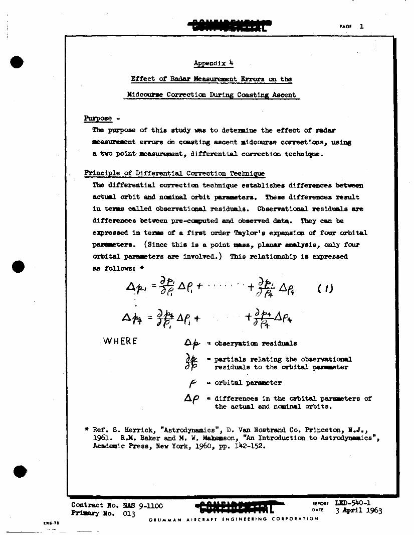
EWC.71 _ -
PAGE 1
Appendix 4
Effect of Radrv Meas\.rrearent Bm>rs on the
Nidcuurse Correction During C o a s t i n g Ascent
PurBose- The purpose of th is study was to determine the efYect of redar reasurrpent e m on caaoting aseent nidccwse comectime, using a two point masumment, d i m r e n t i d carrectitm technique.
principle O f Differentid C m c t f m WlPliqUe
The differential correction technique eatablishee differences between actaml orbit sn8 nasal orbit paraPreters. These differences result In tenre called obeezvatimal msidw~l.6, O b s e r r a t i d r e s i d w h alre
differences betveen p r e - c q t e d and observed data. expressed in teme of a first mder Taylor's expansion of four orbital -tern. orbital pamm~ters are involved.) a8 follows: *
They can be
(Since this is a p i n t -8, planar is, only four This relatiambip is erpressed
WHERE h#+ = o?Meryatian residW8
$$ = partiale relating the observatianal residuuI.6 t o the orbital psrslreter
f = orbital p-ter
Ap = difference6 in the mital parsPetere of the actual and naniasl orbits.
* Ref , S. Herrick, "Astmdymaics", D. V a n Nostrand Co. Princeton, B.J., 1961. R.M. Baker ~ n d M. W. -on, " ~ n Introductian to Astrodylvuics", Academic Res@, Nev Yark, 1960, pp. 142-152.
G R U M M A N A I R C R A F T E N G l N C E R l N G C O R P O R A T I O N

Procedures snd Asarmqptlans
The purpose of the study i s t o investigate the effectiveness of the Uifferential corxectioa technique vhen radar m e a m a t 8 are ueed t o
t h a t no InJection errors h8ve occurred and that the obaervatimal
residuals t ia t due to radar remurepent errors. As a result, the r idcavse canectlcm vhich results frca the obseniatianal reaidw~ls propegate traJectary position and velocity e m .
O b t 8 i n the ObSemtional IY?SidUalS. T h pethod O f d y S i 6 88-8
Since there are four orbitsl paFePreter differentials t o be evaluated, a iiniPlur of fw obsertatimal residuals are required t o solve for the unk~oms. tu0 rrdrv pamaeters st two separate tlmes. This technique hae the
inherent &vantage of elisinsting 8- radaF pamaeter perf'onrmces requireirents which are crttioL1 OP difficult to achieve. o f Inwetigutian, the radar paraPetere wed far the masureoent we=
Angle mte, was not included becwse preliriraary inwestig.tian
indicated that the orbital &ter detemiaation wae highly sensitive t o ellgular rate aeaeureopnt errors, and the specified accuracies of angular rate being considered f a the rrrdar wuld not f ie ld reasonable infonation.
The necesssry infarmtion h m been obtained by observing
For pwose
ccibhatim of - 9 9 8 range mte#f 8 and lim sight3 e R 0
rp REPORT m-w-1 D A T E 3 April 1963 C o n t r a c t lo. Ius g-lloo
Primary No. 013 G R U M M A N A I R C R A f l 6 N G I N L L R I N G C O R P O R A T I O N
rwa.7r -

Pmcedues and A s ~ a m p t i o a s (Continuedl
The partials described above, which relate the observaticmal residuals to tbe o r b i t a l psraeeters, are tiPle dependent.
+o achieve the best result8 with two -nts of the
it is deeirsble t o separate the t-8 of ae8a-t a6 widely as possible. becares a critical variable af the study.
'Rierefase, in d e r
parareter,
As a cmaeqpence, the effect of varying the tire s e v t i c m
first m w n t (tl) weus aaa\ll#d t o occur . i iateIy after burncut arid the t i m e of the seed measurement ( t e ) AB FAIL- t o rary. The tirve of the midcourse carrectiaol (y) 8 a r b i t r s r l l y set at
fifty aeccrnds after t2.
The midcourse correction errors are prapigated t o poeit ian and velocity errors at variol l6 points along the t rs jectary. the basis of JUaging the effectiveneso of the midcaur8e cormctioa.
Theee e m then form
For t h i s study a Hohnrann t ransfer arbit fmm !5O,OOO ft. t o an a l t i tude of 80 n. miles -8 used t o determine naalnal m h e a of nulge, reoge mte, end line-&-si@& angle. The partials relating the &servatlcmsl
r e S i d ~ d 6 t o orbital paraPPeter8, snd the partials used to obtain the
emor propagatim coefficients, were based on equations vhlch sssmed 8
perfectly cizruLrv &it of the CSM, and a linear expwicm of gravity in tbe v ic in i ty aZ the m. point l t s s snd C C J p l a r w orbits.
. I n additiat, the equatims assuved a
Rswe of Fbmmeters
T$e posi t ion and velocity e m r s were detelpined for the fo l la r lng points:
1. Apocynthim 2.
3. 4. 5.
10 n. miles range frcm apocynthion 20 n. ailes range fran apocyathian 30 n. miles range fraa apocynthlan bQ n. miles range frca apocynthion

The range of accuracies for em., radar parameter used In the study =re:
5 = radar m e (f ) - 0.05$ and 0.5%
IC:! .I xgnge rate (3) - 0.3; LO$, 5.M #
= line-of-sight angle (e, ) - 2 ~UXUI; 4 rrad; 6 ruad K3
output The data is presented in graph fm.
aad velocity errors b V c l and AV c3 of secapzd measurement tp. velocity impulse at midcourse which wwld result fFan the m e a s m n t errors in each of the cases studied.
P o s l t l m e m (AC, and AC ) ) are plotted as functions of time
3
Also plotted as a fuactian of t2 is the
Data for the apocynthion and 30 n. miles fran apocynthion cases were hand plotted, and the autcrrratic platter IWS used for a l l other points
under study.
It should be noted that the data presented consists of biased e m .
Data is 83.80 available an the traJectoay errors due to raadae rsdar
e m .
Tables A4-1, A&-2 and Ah-3 present a ccqarison of the effects of e m s , when considered 86 biased and as mndcm~~ The errors
indicated are in mitian and velocity at apocynthion, when t g is
1675 seconds, far the ccmbinatim of tbe radar panuoeter~ of w e ,
lange rete, and line-of-sight angle.
errors r o r both the biased and rand- cases are of the ixme order of
The cauparison shows the trajectory
-itUk, d2fferL-i by ile llWZT t k i ? a b of tkKi IIl iiiCXt mSe6.
Contract NO. NAS g-uoo Priraary PO. 013
REPORT IED-540-1 3 A 9 r j . l 1963
G R U M Y A N A I R C R A F T f N G l N C E R l N G C O R ? O R A T I O N

PAGE 5
Biased
R a n d o m
I n i t i a l
Biased
R a n d o m
I n i t i a l
Biased
R a n d o m
I n i t i a l .
B i a s e d
Random
In i t i a l .
5
.OOO'j
.0005
.005
.005
. O l O 2.02xlO 4 2.35X11O3 , 2.48 1.42xlO 4 G.2W03 8.47
2. %fi03 4 .87x103 6.79
.003 fy. 73x10~ 7. 8=o2 .858
2 .tl 4. L?XlO3 1.93~10 2
1 . 2 8 ~ 1 0 ~ 1 . 4 8 ~ 1 0 ~ 3 -05
.010 2.8WO 4 3.35x10³ 3.95
2.4Gx10 4 7.53~1-o3 10.4
8 . 0 0 ~ ~ 1 ~ 5 . 0 9 ~ ~ 0 ~ 6.92
7.33 1.54~10 4 1.79xlO
2.07xlO 4 4 . 5 7 ~ ~ 1 ~ 6.51 .003
G.33xI.o 3 1.6gxl.o 2.17
Radar Parameter Combination
- Range & Rarqe L%te r.?) - . Table Ab-1
- -374
4.33
.181
- -127
1.30
.074
- .5C1
4.40
.424
- .314
1.51
.321
11.6
8.25
-
3.86
2.59
-
16.6
13.7
-
8.84
11.3
-
Contract No. I U S 9-1100 REPORT LED-540-1 PrinrarY 110, 013 DATE 3 Apri l 1363
C R U M M A N A I I C # A f I E N G I N E L R l N G C O I C 0 R A 1 I O N
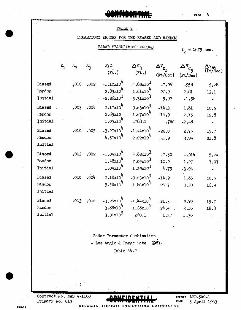
,
Biased
Randorn I n i t i a l
Massd . Random Tnit ial
Biased
Raudm I n i t i a l
Biased Random Initial
Biased Random
I n i t i a l
Biased
Random Initial
TABLE 2
-TORY ZFU3ORS FOR TEIE BIASED AND RANDC&l
RADAR MEASURENENT ERRORS
5 . 5 5
*010 .002
.010 .005
,003 .002
.010 .004
.003 .oo6
ncl A c3 AVC1 (Ft 1 (Ft/sec)
4 -1 .~OXI.O - 4 . 8 2 ~ 1 0 ~ - 7 , s
-2.26xl.o 3.3lxlO ’ 5.92 2299
4 2.83~10 1.61xI-0
9.63d03 -14.3 16.9 4
4 -2.17flO 2.65~10 1.67~10 1.05~10 -788.1 ,782
4 - 3 . 2 ~ 0 ~ -1.44xl.O -22,O 4.57X10 2.22xlo 31.9
-1 .ow0 4 . 8 2 ~ 1 0 ~ -7 e 3 0 7.ogx1-0~ 10.2
1.22xlo 4*75
4 4
4
1.48X10
1 .ow0
-14.9 26.7
-2.18~10 - 9 . 6 ~ 0 ~ 4 3.58~10 1.86xlo
4 -3 .26fi04 -1 .&Xl.O -21.3 3.88~10 1.68xlO 24.4 ,
3 .91xlO 260.1 1.37
Radar Parameter Combination b - LOS Angle & Rawe Late (e9)-
Table Ab-2
t2 = 1675 sec.
n v c 3 (Ft/SeC 1
,958 2.81 -I 058
1.81
-2.48 2.15
2 -75 3.99
- 914 1.27
-3.94
1.85 3 030
2.70 3 .lo -: .30
AV (Ftrsec)
5.28 13.1
- x0.5 12,8
c
15.7 21.8
5.24 7 e 0 7 c
10.5 16.9
15.7 18.8
-
Contract Iio. NAS 9-1100 REPORT ~ ~ - 5 4 O - 1 pr imuy NO. 013 3 Apri l 1963
G R U M M A W A I R C R A F T f N G l N r C R l N G C O R P O R A T I O N

Biased Randm
Initial
Biased Random I n i t i a l
Biased Random
I n i t i a l
Biased Random I n i t i a l
Biased Random I n i t i a l
Biased Random I n i t i a l
D o 0 0 5
.0005
.005
.005
.005
,0005
7 .G7fio3 5.28~10~
.004 5.68~10~ 8.76~10~ 6 3 x 1 0 ~
.006 8.45a03 7.88~10~ 3.06~10~
3 .3w03 3 .68d03 1 .55x103
6. 7m03 3'
3. 3w03 4 1 . o m 0 4 1.18xlo
3. i w o 3
3. rcOfio3 5 .66flo3
6. 7w03 8 .48d03 1.35X10³
4 1 . o m 0 4 1 .lox10
5 . omo3
7.31x10
-416.5
Radar Parameter Canbination
- - w e & IDS h d e (fe) Table Ab-3
AVC 1 (W*) 4.64 5.01 1.49
9.24 9.96 3-29 .
14.3 16.4 2.18
5.09 8.40
' -1.44
9.66 12.0
36.8
13.8 14.9
5 .l-l
3
2.32
2.57 -2.18
A V C
(W-)
4.64 5 J 3 -4 . 37 6.93 7.73 -6.39
2.29 2.66 -1.99
4.61 5.18 -4 -19
6.96 7.69 -6 57
1.45 1.57
- 2.90 3.08
- 4.36 5 06-7 -
1.46 3.66
- 2.91 4.52
- 4.36 4.61
-
Contract NO. rw g-1100 e-. No. 013 DATE 3 April I N 3
REPORT LED-540-1
C R U M Y A W A I R C R A F T E N G I N E E R I N G C O R P O R A T I O N

Appendix 2 Telminal Guidance Trajectory Analy sis
Purpose - This analysis was ini t ia ted w i t h the folloving obJectives:
1) Determine the radar Ix)s rate accuracy required t o rendezvous successfully, using the GAB2 - proposed LE4 rendezvous guidance scheme.
2) Determine theAV required to perfom the terminal guidance mission.
A tvo-degree of freedan, point mass, d ig i t a l canputer progrem WBS implemented
1) &fore i n i t i a t i n g rendezvous, the LEM is rotated so that the b ~ d y ~g-axie is pointed along the l i ne of si&t t o the CSM.
2) The LIW is then rotated about the ZB-&X~S u n t i l the body XB-aXl.3 is parallel t o the caaponent of re lat ive velocity perpendicular t o the l i n e of-sight. This a t t i tude i s nuw held constant throughout rendezvous, so that the %-axis =action jets nray be used t o adjust closing velocity, or range rate, and the XB-aXiS reaction jets used t o nu l l fx)6 rate.
3) A t a specif ied inititii , rendezvous range, the XB'aXis reaction jets (4 - 400 pounds of thmst) are used t o reduce the rXa nnte t o a minima value.
4) A f t e r the UE rate is nulled, the range rate i s aiiJuated with - + 200 lbs of thrust to fall vithin the specified renge rate 1 W t s cor=spding to that range.
Procedure - with the following rendezvous procedures:
5) The LEX then coasts u n t i l the next range t e s t point is reached, a t which ' time steps (3) and (4) are repeated in the 8- sequence. is followed for a discrete number of range t e a t points.
This procedure
Parameters Studied A. Ascent Trajectory Errors
The chosen nuninal !l!rajectory has a pericynthion of 50,000 feet, and a CSW-LEX collision a t an apocynthian of 80 I.bLI. abuve the 1- surface, as shown by curve 2 i n figure A5-1. resulting during boost vere chosen as the largest expected o f f - n d n a l variations
encountered by the LE?4. in ufiich boost ends vhen the integrated specif ic force has reached a prescribed value.
The free-fright t ra jec tor ies thxust ruqpitude variations of + - Z$ from the n a n i a
These cutoff errors ax% based on a boost progrsm
Contract MO. BTAS g-l.1.00 R L N n l Irgo - 540-1 3 April 1963
G I U M M A W A I R C R A F T E ~ G I N C K R I N O C O R ? O R A T I O N Primary 100. 013

Parameters Studied (continued) B. I n i t i a I Rendez-sous Range
For the naninal (6 variat ion ascent t ra jector ies , rendezvous w a s i n i t i a t ed a% 40,30,20, and 14 N.MX. B e 14 n.mi. range was chosen because the f 2% t h s t free f l i g h t trajectories have a minimum miss distance which mls just with4 the 14 n.mi. w e .
C. XdS RAB ACCURAC-IES The e f f ec t s of varying of the minimum UE rate attainable by the LEM radar on canpleting mndemous were investigated. and 1.0 mil l i r ad ibs / sec were studied as the minimum KS rate tha t are at ta inable by the radar.
th rus t variation) and the plus and minus th rus t
IL6 rates of 0.2, 0.5,
Results Figure A 5 - 1 shows the nominal and plus and minus 2$ th rus t f E e - f l i g h t t ra jec tor ies as so l id lines, and the rendezvous t ra jec tor ies i n i t i a t e d frcm a range of 40 N,MI. as dashed l ines . The s teps a t which IL)ri rate and range r a t e corrections w e r e performed are indicated by triaagles on the rendezvous t ra jector ies . The relationship between maximum allowable I,CS ra t e and rendezvous miss
distances a r e shown i n figure A5-2 fo r the + and -6 th rus t rendezvous t ra jec tor ies . fran Variations i n thrust magnitude during boost, the Lo6 rate must be
reduced t o within 0.2 miUiradians/sec. t o assure rendezvous.
T h t S required for rendezvous as a f b c t i o n of i n i t i a l rendezvous range
i s shown i n figure A5-3. The plus and minus 3'$ th rus t rendezvous t ra jec tor ies have been included here as a loss f o r canparison with the
+2$ - th rus t t ra jec tor ies . the IDS rate was nulled t o a resolution of 0.2 miUiradians/sec during
The study indicates t ha t f o r the errors at cutoff msul t ing
For the t ra jec tor ies indicated i n figure A5-3,
' rendezvous I021 ra te adjus-tments. Figures As-l'through 3 present the resu l t s pertaining t o a nauinal Holn~m~n transfer. Corresponding results for a higher energy t r aas fe r (m'naninal central angle t o rendezvous) are sham i n Figs. As-4-6.
CoRtnct NO. NAS 9-1100 RLPORT - 5M-l P r i m = No. 013 DATE 3 April 1963
G R U M M A N A l R C R A f l L N G I N E I R I N O C O R P O R A T I O N

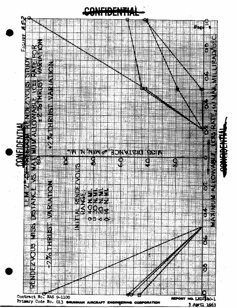


. ..

Cor pr


![Day6 - Aarhus Universitetbiostat.au.dk/teaching/basicbiostat/files/day6_onepage.pdf · Title: Microsoft PowerPoint - Day6 [Compatibility Mode] Author: epar Created Date: 10/10/2016](https://img.dokumen.tips/doc/110x75/5fc46928499e5b4efa152609/day6-aarhus-title-microsoft-powerpoint-day6-compatibility-mode-author-epar.jpg)