Embed Size (px)
Citation preview

WARNING!For a full understanding of the performance characteristics of this equipment, the user should carefully read this manual before use of the device.
Emergency ventilatorInstructions for Use
Oxylog 1000
MT-
974-
2000

Contents
1
Contents
For Your Safety and that of Your Patients . . . . . . . . . . . . . . . . .3
Precautions . . . . . . . . . . . . . . . . . . . . . . . . . . . . . . . . . . . . . . . . . .4
Intended Use . . . . . . . . . . . . . . . . . . . . . . . . . . . . . . . . . . . . . . . . .4General description. . . . . . . . . . . . . . . . . . . . . . . . . . . . . . . . . . . . .4
Operating concept . . . . . . . . . . . . . . . . . . . . . . . . . . . . . . . . . . . .5
Operation . . . . . . . . . . . . . . . . . . . . . . . . . . . . . . . . . . . . . . . . . . . .6Oxylog 1000 Device Check . . . . . . . . . . . . . . . . . . . . . . . . . . . . . .6IPPV controlled ventilation . . . . . . . . . . . . . . . . . . . . . . . . . . . . . . .7Ventilation with PEEP (Special accessory). . . . . . . . . . . . . . . . . .9End-expiratory volume measurement (Special accessory) . . . . .10End of operation . . . . . . . . . . . . . . . . . . . . . . . . . . . . . . . . . . . . . .10
Care. . . . . . . . . . . . . . . . . . . . . . . . . . . . . . . . . . . . . . . . . . . . . . . .11Dismantling . . . . . . . . . . . . . . . . . . . . . . . . . . . . . . . . . . . . . . . . . .11Disinfecting/Cleaning . . . . . . . . . . . . . . . . . . . . . . . . . . . . . . . . . .12Sterilising . . . . . . . . . . . . . . . . . . . . . . . . . . . . . . . . . . . . . . . . . . . .13
Preparation . . . . . . . . . . . . . . . . . . . . . . . . . . . . . . . . . . . . . . . . . .14Mounting the ventilation valve . . . . . . . . . . . . . . . . . . . . . . . . . . . .14Installing the Oxylog 1000 . . . . . . . . . . . . . . . . . . . . . . . . . . . . . .15Connecting the O2 supply . . . . . . . . . . . . . . . . . . . . . . . . . . . . . .16
Checking readiness for operation. . . . . . . . . . . . . . . . . . . . . . .18Testing ventilation function . . . . . . . . . . . . . . . . . . . . . . . . . . . . . .18Testing the »Paw >« alarm. . . . . . . . . . . . . . . . . . . . . . . . . . . . . .19Testing the »Paw <« alarm. . . . . . . . . . . . . . . . . . . . . . . . . . . . . .19Checking the »Psupply« alarm . . . . . . . . . . . . . . . . . . . . . . . . . . .20
Troubleshooting. . . . . . . . . . . . . . . . . . . . . . . . . . . . . . . . . . . . . .21
Maintenance intervals . . . . . . . . . . . . . . . . . . . . . . . . . . . . . . . . .22
What's what . . . . . . . . . . . . . . . . . . . . . . . . . . . . . . . . . . . . . . . . .23Front view. . . . . . . . . . . . . . . . . . . . . . . . . . . . . . . . . . . . . . . . . . . .23Side view . . . . . . . . . . . . . . . . . . . . . . . . . . . . . . . . . . . . . . . . . . . .24
Technical data . . . . . . . . . . . . . . . . . . . . . . . . . . . . . . . . . . . . . . .25
Abbreviations and symbols. . . . . . . . . . . . . . . . . . . . . . . . . . . . .27
Appendix . . . . . . . . . . . . . . . . . . . . . . . . . . . . . . . . . . . . . . . . . . . .28Minute volume and O2 concentration as a function of airway pres-sure . . . . . . . . . . . . . . . . . . . . . . . . . . . . . . . . . . . . . . . . . . . . . . . .28Block circuit diagram. . . . . . . . . . . . . . . . . . . . . . . . . . . . . . . . . . .29
Order List . . . . . . . . . . . . . . . . . . . . . . . . . . . . . . . . . . . . . . . . . . .30
Index . . . . . . . . . . . . . . . . . . . . . . . . . . . . . . . . . . . . . . . . . . . . . . .31

Contents
2
This page is intentionally left blank

3
For Your Safety and that of Your Patients
For Your Safety and that of Your Patients
Definitions
Strictly follow these Instructions for Use
Maintenance
Accessories
Do not use accessory parts other than those in the order list.
WARNING!A WARNING statement provides importantinformation about a potentially hazardous situation which, if not avoided, could result in death or serious injury.
CAUTION!A CAUTION statement provides important information about a potentially hazardous situation which, if not avoided, may result in minor or moderate injury to the user or patient or in damage to the equipment or other property.
NOTE:A NOTE provides additional information intended to avoid inconvenience during operation.
WARNING!Strictly follow these Instructions for Use.Any use of the product requires full understanding and strict observation of all portions of these instructions. The device is only to be used for the purpose specified under"Intended Use" on page 4 and in conjunction with appropriate patient monitoring (see page 6). Observe all WARNING and CAUTION statements throughout this manual and all statements on device labels.
WARNING!The device must be inspected and serviced regularly by trained service personnel.Repair of the device may also only be carried out by trained service personnel.Dräger recommends that a service contract be obtained with DrägerService and that all repairs also be carried out by them. Dräger recommends that only authentic Dräger repair parts be used for maintenance. Otherwise the correct functioning of the device may be compromised.See chapter "Maintenance Intervals".
Liability for proper function or damage
The liability for the proper function of the apparatus is irrevocably transferred to the owner or operator to the extent that the apparatus is improperly serviced or repaired by personnel not employed or authorized by DrägerService or if the apparatus is used in a manner not conforming to its intended use. Dräger cannot be held responsible for damage caused by non-compliance with the recommendations given above. The warranty and liability provisions of the terms of sale and delivery of Dräger are likewise not modified by the recommendations given above.
Dräger Medical b.v., Best, the Netherlands
Precautions
4
Precautions
Intended Use
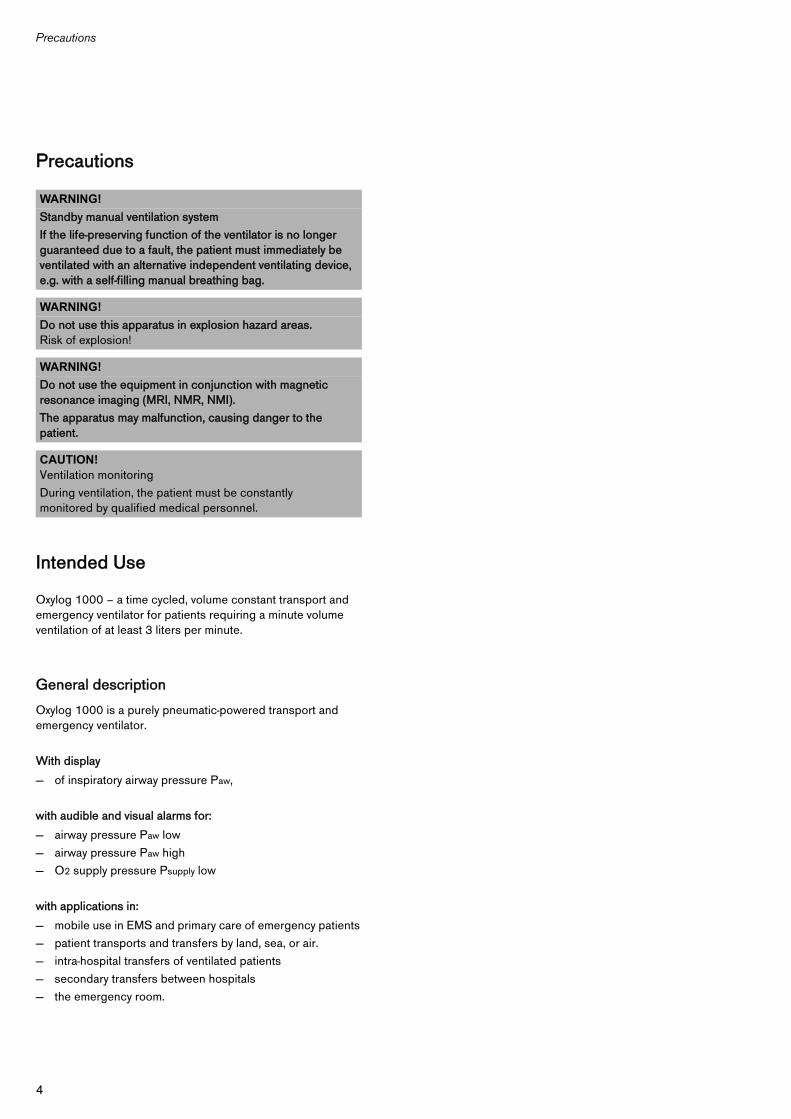
Oxylog 1000 – a time cycled, volume constant transport and emergency ventilator for patients requiring a minute volume ventilation of at least 3 liters per minute.
General description
Oxylog 1000 is a purely pneumatic-powered transport and emergency ventilator.
With display
— of inspiratory airway pressure Paw,
with audible and visual alarms for:
— airway pressure Paw low— airway pressure Paw high— O2 supply pressure Psupply low
with applications in:
— mobile use in EMS and primary care of emergency patients— patient transports and transfers by land, sea, or air.— intra-hospital transfers of ventilated patients— secondary transfers between hospitals— the emergency room.
WARNING!Standby manual ventilation systemIf the life-preserving function of the ventilator is no longer guaranteed due to a fault, the patient must immediately be ventilated with an alternative independent ventilating device, e.g. with a self-filling manual breathing bag.
WARNING!Do not use this apparatus in explosion hazard areas. Risk of explosion!
WARNING!Do not use the equipment in conjunction with magnetic resonance imaging (MRI, NMR, NMI).The apparatus may malfunction, causing danger to the patient.
CAUTION!Ventilation monitoringDuring ventilation, the patient must be constantly monitored by qualified medical personnel.

5
Operating concept
Operating concept
1 Three rotary control knobs are located in the middle of the front panel for setting the upper alarm limit for airway pressure (»Pmax«), the ventilation rate (»Freq.«) and the minute volume (»MV«).Uniform colour codes are used to identify different scale ranges of the »Freq.« and »MV« knobs to help rapid presetting: with these colour-coded scales, the initial parameters are adapted to the relevant patient group: infants (green) / children (blue) / adults (brown).
2 The main switch 0/I for switching the ventilator on and off is in the bottom right-hand corner of the front panel.
3 With the »Air Mix/No Air Mix« switch, the user can choose between approx. 60 Vol.% O2 and 100 Vol.% O2.
4 The pressure gauge shows the inspiratory airway pressure.
MT-
214-
99A
NOTE:The color coded ranges and patient identifications are offered solely for the convenience of the user for selecting initial settings. It is ultimately the responsibility of the user to select the correct settings for each patient.
4 1 1 1 2
3
9 8 7 6 5
The flag indicators for the alarms are located above the rotary control knobs for »Freq.«, »MV« and »Pmax«:
5 »Psupply« flag indicator.Green if the supply pressure is sufficient, turns red if the supply pressure is insufficient.
6 Indicator for the upper alarm limit »Paw >« .Red if the airway pressure exceeds the maximum limit.
7 Indicator for lower alarm limit »Paw <« turns red if lower alarm limit is not reached.
8 »g«button to mute the audio alarm for up to 2 minutes.9 Indicator »g« turns yellow when the alarm tone is muted.

Operation
6
Operation
Oxylog 1000 Device Check
The device check must be carried out before each use. Any operation of the device requires thorough knowledge of the Instructions for Use.
Check the following points before starting up the device:● O2 pressure supply connected ● Cylinder pressure at least 100 bar or ventilator
connected to the central O2 supply ● Ventilation valve and ventilation hose connected
Testing correct operation
● Fit the test lung to the ventilation valve.● Set the device when using a reusable hose:
»MV« approx. 10 L/min »Freq.« approx. 10 bpm »Pmax« approx. 55 mbarMain switch I (ON)Switch »No Air Mix«
● Set the device when using a disposable hose to the settings as described in the accompanying leaflet of the disposable hose.
● Squeeze the test lung, so that the airway pressure is approx. 60 mbar.
● Remove the test lung:
Type
Serial No.
Oxylog 1000 must ventilate the test lung After 5 ventilation strokes ventilation is constant, no alarms should occur.
The »Paw >« indicator turns red, and the audible alarm is sounded.
The »Paw <« indicator turns red, and the audible alarm is sounded.

7
Operation
In the event of deviations, see "Troubleshooting", page 21.
Use a prepared, operable and disinfected device. Care, page 11. Preparation, page 14. Checking device ready for operation, page 18.
IPPV controlled ventilation
For ventilation frequencies of 4 to 54 breaths per minute.
For rapid presetting, uniform colour-coded scale ranges can be used for the rotary control knobs for the ventilation rate Freq. and minute volume MV.1 Presetting the »Freq.« and »MV« control knobs:
Device check completed
Name
Date
Patient group Freq.1/min
MVL/min
Green range for infants
28 to 54 3 to 5
Blue range for children
20 to 28 5 to 9
Brown rangefor adults
4 to 20 9 to 20
NOTE:The color coded ranges and patient identifications are offered solely for the convenience of the user for selecting initial settings. It is ultimately the responsibility of the user to select the correct settings for each patient.
002
D Oxylog 1000
1 1

Operation
8
The I/E-ratio is fixed to approximately 1:1.5 and changes slightly depending on the setting. The I/E-ratio is within the range considered reasonable for most patients during emergency care and transport.
2 Set the desired O2 concentration with the switch:Air Mix approx. 60 % O2 by volumeorNo Air Mix = 100 % O2 by volume
Set »Pmax«
When the patient is connected:1 Check the »MV« setting and adjust according to the patient.2 Check the airway pressure on the pressure gauge.3 Set desired upper alarm limit »Pmax«.When the desired upper alarm limit set »Pmax« is reached, the machine limits the airway pressure increase by blowing off part of the inspiratory flow. Inspiration is continued by the machine.
NOTE:The tidal volume will be equal to the minute volume setting divided by the rate setting:
Minute volume Ventilator Rate (1/min)(L/min) 5 10 25 35 54 (max)
3 0.60 0.30 0.12 0.09 0.06
7 1.40 0.70 0.28 0.20 0.13
10 2.00 1.00 0.40 0.29 0.13
15 3.00 1.50 0.60 0.43 0.28
20 4.00 2.00 0.80 0.57 0.37
Tidal volume VT (L)
WARNING!In Air Mix mode, the applied tidal volume VT is reduced at high airway pressures due to the physical characteristics of the injector used for the mixing and the O2 concentration increases due to the smaller amount of air intake. (See also page 28 in the appendix).
WARNING!In toxic surroundings:— The patient must be ventilated in No Air mix mode in order
to ensure that toxic constituents are not entrained into the breathing gas.
— The patient must immediately be transferred to a breathable atmosphere in order to prevent inhalation of toxic air when spontaneous breathing resumes.
WARNING!Watch the pressure gauge and take note of alarm conditions in order to recognise incorrect ventilation at an early stage and prevent danger to the patient.
003
D 2
004
D
132
Oxylog 1000

9
Operation
For heart-lung resuscitation
For resuscitation of adults using the "two helper method":4 Set the »Freq.« knob to the heart symbol H, 5 Set the »Pmax« knob to the heart symbol H,
approx. 55 mbar.
Ventilation with a mask
● Connect mask to patient connection on breathing valve.● Position mask over the face to cover the bridge of the nose
and the chin, to ensure a tight fit.
Ventilation with PEEP (Special accessory)
1 Set the PEEP valve to 0 mbar = turn the knob anti-clockwise as far as it will go and fit it to the expiration connector of the ventilation valve.Set PEEP = turn knob. The end-expiratory pressure is increased by the set PEEP value.
NOTE:Airway pressure limiting is now activated. When the peak pressure limit is reached, tidal volume may not be fully applied under certain conditions.
NOTE:The PEEP pressure is not displayed on the pressure gauge!
006
D
5 4
Oxylog 1000
028
028
D Oxylog 1000
1

Operation
10
Only for stationary use!
End-expiratory volume measurement (Special accessory)
To measure the end-expiratory tidal volume and end-expiratory minute volume.Cannot be combined with the PEEP valve.
2 Clamp the Volumeter 3000 holder to the wall rail.3 Screw the Volumeter 3000 to the holder.4 Screw the elbow connector to the Volumeter 3000.5 Fit adapter to expiration connector of the ventilation valve.6 Connect the ventilation valve and Volumeter 3000 with
1.5 m long ventilation hose.
End of operation
After disconnecting the patient:1 Switch the main switch to 0.
If the Oxylog is supplied by O2 cylinder:● Fully close the cylinder valve.
If the Oxylog is supplied by the central gas supply:● Remove the gas supply connector.
NOTE:Strictly follow the Instructions for Use of the Volumeter 3000.
009
5
64
3
2
D Oxylog 1000
010
D Oxylog 1000
1

11
Care
Care
● After each operational use of the ventilator, dismantle and disinfect the reusable ventilation valve and ventilation hose, the volume metering parts and the reusable PEEP valve.
● The ventilator and compressed gas hoses must also be cleaned/disinfected if severely soiled.
● Use the single-use system, consisting of the ventilation valve, the ventilation hose and the single-use PEEP valve, only once. These parts are marked:For single use only!
● Dispose of the single-use components in accordance with local regulations.
Dismantling
● Remove Oxylog 1000 from its holder.1 Unscrew the O2 compressed gas hose from the
Oxylog 1000.2 Remove the ventilation hose from the connector on the side
of the ventilator.
● Remove the ventilation valve from the ventilation hose.● Pull the PEEP valve out of the ventilation valve,
or● remove and dismantle the volume metering parts.
CAUTION!To remove the ventilation hose, always grip it by the sleeve and not the spiral stiffening ridges.Otherwise the spiral ridges may be torn, e.g. at the sleeve, or the hose may be ripped out of the sleeve.
011
2 1
012

Care
12
Dismantling the ventilation valve
Turn the cover about 45o anti-clockwise = unlock, and remove the cover.3 Remove the diaphragm. Do not dismantle any further.
Disinfecting/Cleaning
Use only preparations classified as »surface disinfectants« for disinfecting. For material compatibility, we recommend preparations based on— aldehydes, — alcohols, — quaternary ammonium compounds.
Due to possible damage to materials, the following preparations are unsuitable: — compounds containing alkylamine— compounds containing phenol— halogen-releasing compounds— strong organic acids— oxygen-releasing compounds.For users in the Federal Republic of Germany, we recommend the use of disinfectants listed in the current DGHM list (DGHM = German Society for Hygiene and Microbiology). The DGHM list (published by mhp Verlag GmbH, Wiesbaden) also specifies the active basis of each disinfectant. For countries where the DGHM list is unavailable, we recommend products based on the above active bases.
WARNING!Protect the diaphragm from damage.
WARNING!Do not allow any foreign matter to enter the housing of the ventilation valve.
WARNING!The red non return valve in the diaphragm should not be removed, damaged or bent. Otherwise, impaired valve operation will occur, putting the patient at risk.
013
1
2

13
Care
Wipe disinfecting
Ventilator, O2 compressed gas hose:● Wipe disinfect with e.g. Buraton 10 F or Terralin. Strictly
follow the Instructions for Use of the disinfectant manufacturer. Coarse impurities must first be removed with a disposable cloth.
Immersion disinfecting
Dismantled components of the ventilation valve, ventilation hose, volume metering parts, not the Volumeter 3000:● Disinfect in disinfectant bath with e.g. Gigasept FF =
formaldehyde-free. Strictly follow the Instructions for Use of the disinfectant manufacturer. Thoroughly stir the parts in the solution.Do not clean with hard brushes.Do not allow any foreign object to enter the inside of the ventilation valve.
● Rinse thoroughly with Aquadest.
Sterilising
Sterilise as follows if necessary:Disassembled parts of the breathing valve, ventilation hose and mask:● Sterilise in hot steam at 134 oC. Exposure time in
accordance with EN 285: at least 3 minutes.
PEEP valve and Volumeter 3000
● treat as specified in their specific Instructions for use.
After care
● Preparation, page 14.● Connect the O2 supply, page 16.● Betriebsbereitschaft prüfen, page 18.
CAUTION!Do not allow any liquids to penetrate inside the ventilator or O2 compressed gas hose.Liquid inside the system can impair ventilation.
CAUTION!Allow the parts to dry fully. If any water remains in the ventilation valve, the ventilation function may be impaired.
NOTE:Do not expose the plastic parts to the hot steam for more than 10 minutes, since this can accelerate the ageing of the materials.

Preparation
14
Preparation
The reusable ventilation hose and the ventilation valve are supplied with the ventilator.Alternatively, the optional, pre-assembled singe-use system, consisting of a ventilation hose and ventilation valve, can be used. These parts are marked:For single use only!
Mounting the ventilation valve
1 Check that the red non-return valve is securely seated in the diaphragm and lies flat on the diaphragm.
2 Insert the diaphragm in the valve housing, with the red non-return valve facing the housing.
3 The bead of the diaphragm must lie flat and flush on the edge of the housing.
4 Fit the cover as shown, press down and turn 45° clockwise to lock.The inspiration connector and the expiration connector should be facing one another. The diaphragm should fit into the housing without creasing.
5 Fit the ventilation hose to the inspiration connector of the ventilation valve.
6 Fit the ventilation hose to the connector on the ventilator.
WARNING!The red non return valve in the diaphragm should not be removed, damaged or bent. Otherwise, impaired valve operation will occur, putting the patient at risk.
014
1
2
3
4
015
5
016
6

15
Preparation
Mounting the PEEP valve (option)
Both a reusable PEEP valve and a single-use PEEP valve are available.The single-use PEEP valve is marked:For single use only!● Mount the PEEP valve on the expiration connector of the
ventilation valve.Measurement of the expiratory volume is not possible when the PEEP valve is used.
Installing the Oxylog 1000
For stationary use
● Place firmly on a level, non-slip surface, ensuring unit cannot fall,or:
● Suspend at the head of the bed,or:
● Suspend on a wall rail, as illustrated.
For mobile use in vehicles
● Use the vehicle mount1 Suspend Oxylog 1000 by its bracket on the rod of the
holder.2 Swivel the ventilator up into the holder until it clicks into
place.
To pull out the ventilator:3 Press the release catch from underneath.
029
017
D Oxylog 1000
018
1
2
3

Preparation
16
Connecting the O2 supply
Take care when handling oxygen.
For supply by O2 cylinder
Use full cylinders with 200 bar cylinder pressure.● Screw a pressure-reducing valve onto the O2 cylinder (for
supply pressure 2.7 to 6.0 bar).
● Connect the Oxylog 1000 to the pressure-reducing valve with the compressed gas hose.
● Open the cylinder valve by turning slowly as far as it will go.
WARNING!O2 is highly flammable and intensively propagates any source of fire.Do not smoke or allow any naked flame in the vicinity of the O2 supply. Protect O2 cylinders against falling, and do not expose them to intense heat.
WARNING!Do not oil or grease O2 fittings, such as cylinder valves and pressure-reducing valves, and do not handle these parts with greasy hands. Fire risk.
WARNING!Only open/close cylinder valves by hand, turning evenly. Never use a tool to open/close the valves.
WARNING!Use only compressed gas cylinders that conform to national safety standards and have been duly approved.
WARNING!Use only pressure-reducing valves with an outlet exhaust valve that limits the outlet pressure to approx. 5 bar in the event of failure.
CAUTION!Do not insert metering valves or flow meters in the O2 supply of the Oxylog 1000.Risk of impaired function of the ventilator with consequent danger to the patient.
019
O2

17
Preparation
Determining the gas content of the O2 cylinder
Example:Cylinder pressure measured at the pressure gauge of the pressure-reducing valve: 200 barO2 cylinder capacity: 2.5 LCompressed gas content: 2.5 L x 200 bar = approx. 500 L
Estimated operating time of the Oxylog 1000
Example:Freq. 10 bpm, VT = 1 L, MV = 10 L/min
Operating time =
Operating time = = approx. 45 min
If Oxylog 1000 is switched to »Air Mix«, the gas consumption is reduced by about 50 %, thereby increasing the operating time to about 90 minutes.
For supply from a central O2 supply ● Screw the compressed gas hose to the Oxylog 1000 and
insert the gas connector in the O2 supply socket.
In exceptional cases, the Oxylog 1000 may also be supplied with compressed air, in which case the O2 concentration is always 21 % by volume.
For use with the Dräger Oxator
● Screw the O2 compressed gas hose to the Oxylog 1000.● Insert the gas connector securely into one of the two O2
ports until it clicks into place.
_________* Intrinsic consumption of the device: approx. 1 L/min
NOTE:Strictly follow the Instructions for Use of the Oxator.
Compressed gas content [L](MV +1*) [L/min]
50011
020
021

Checking readiness for operation
18
Checking readiness for operation
— after changing the ventilation valve,— after each care and reassembly procedure,— at the latest every 6 months.● ocument testing in the medical products book.
Connecting the test lung
The test lung consists of the mask elbow for connecting to the ventilation valve, the Ø7 catheter connector for simulating the resistance of the airways and a 2 L breathing bag to simulate lung compliance.● Insert the mask elbow of the test lung onto the patient
connector of the ventilation valve.
Switch on the O2 supply
● Open the O2 cylinder supply by turning slowly as far as it will goor
● insert the O2 compressed gas connector in the supply socket until it clicks into place = tapping position.
Testing ventilation function
● Set the ventilator when using a reusable hose:1 »MV« knob approx. 10 L/min2 »Freq.« knob approx. 10 bpm3 »Pmax« knob approx. 55 mbar4 Main switch I (On)5 Switch »No Air Mix«
● Set the device when using a disposable hose to the settings as described in the accompanying leaflet of the disposable hose.
● Oxylog 1000 ventilates the test lung.After 5 ventilation strokes ventilation is constant, no alarms should occur.
022
023
D Oxylog 1000
123 4
5

19
Checking readiness for operation
Testing the »Paw >« alarm
With the existing setting1 Keep test lung completely deflated and observe pressure
gauge:● Oxylog 1000 limits the airway pressure to approx. 55 mbar.2 The »Paw >« indicator turns red, and the audible alarm is
sounded.1 Release the test lung.2 The »Paw >« indicator and audible alarm are deactivated.
Testing the »Paw <« alarm
With the existing setting3 Remove the test lung from the ventilation valve:4 The red »Paw <« indicator is displayed, and the audible
alarm is sounded.5 Press the »g« button,4 The »Paw <« indicator remains red; the audible alarm is
muted for up to 2 minutes.6 The indicator »g« turns yellow to indicate that the alarm
tone has been muted.
3 Refit the test lung:4 The »Paw <« indicator and audible alarm are deactivated.
024
1
D Oxylog 1000
2
025
3
D Oxylog 1000456

Checking readiness for operation
20
Checking the »Psupply« alarm
● Switch off the gas supply.Close the cylinder valve or remove the compressed gas connector.
1 The colour of the »Psupply« indicator changes from green to red, but there is no audio alarm in this case.
● Restore the gas supply:1 The colour of the »Psupply« indicator changes from red to
green.
● Remove test lung from ventilation valve.
After all tests have been successfully completed, the ventilator is ready for operation.
026
D Oxylog 10001

21
Troubleshooting
Troubleshooting
This table is intended to assist the user to detect the underlying cause in the event of an alarm and to remedy the situation rapidly.
Fault Cause Remedy
Ventilator does not build up any airway pressure»Psupply« indicator red
Gas capacity of O2 cylinder fully spent. Immediately connect the ventilator to a full O2 cylinder.
Supply pressure at ventilator inlet too low; no central gas supply or O2 cylinder empty.
Establish sufficient supply pressure:2.7 to 6 bar.
Ventilator remains on »Inspiration« Supply pressure at ventilator inlet too low.
Establish sufficient supply pressure: 2.7 to 6 bar.
Oxylog 1000 faulty. Call Dräger Service.
Patient cannot exhale, or can only exhale with difficulty
Ventilation hose kinked. Route the ventilation hose without kinking it.
Red non-return valve in the diaphragm is faulty or »creased«.
Open the ventilation valve and assemble correctly, see page 14.
»Paw >« indicator redAudible alarm is sounded The minute volume is not fully applied
Stenosis in the airways. Free the airways.
Ventilation hose kinked. Route the ventilation hose without kinking it.
Lung compliance reduced. Set the »Pmax« higher.
Patient is "fighting the ventilator" Change the ventilation pattern or sedate the patient.
»Paw <« indicator redAudible alarm is sounded
Disconnection/leakage at the patient connection, ventilation valve or ventilation hose.
Ensure that all connections are leakproof.
Diaphragm of the ventilation valve incorrectly fitted or damaged.
Mount the diaphragm correctly, or replace diaphragm if faulty – see page 14. Replace the single-use system.
Leaky cuff. Inflate the cuff and check for leaks.

Maintenance intervals
22
Maintenance intervals
Clean and disinfect the ventilator or parts before each repair, even if returning components to the factory for repair.
Disposing of the apparatus
— At the end of the period of use.— Dispose of Oxylog 1000 correctly, after consulting the
appropriate disposal contractors.Relevant legal provisions should be complied with.
Inspection and servicing of the ventilator
Every 2 years by trained and qualified personnel.
Pressure-reducing valve Major overhaul in accordance with the operating instructions for the pressure-reducing valve by trained and qualified personnel.

23
What's what
What's what
Front view
1 Main switch 0/I2 »MV« rotary control knob for minute volume 3 »Freq.« rotary control knob for ventilation frequency4 Rotary control knob for upper alarm limit »Pmax«5 Pressure gauge for inspiratory airway pressure6 Indicator »g« to mute audible alarm tone7 »g« key for muting the audible alarm tone8 Indicator »Paw <« (Paw lower alarm limit)9 Indicator »Paw >« (Paw upper alarm limit)10 Indicator »Psupply« for supply pressure11 »Air Mix / No Air Mix« switch
MT-
214-
99A
11
5 4 3 2 1
6 7 8 9 10

What's what
24
Side view
1 Connection for ventilation hose and ventilation valve2 Connection for O2 compressed gas hose
MT-
975-
2000
1 2

25
Technical data
Technical data
Environmental conditions
Operation
Temperature –18 to 50 oC
Atmospheric pressure 700 to 1100 hPa
Humidity 15 % to 95 % r. h.
Storage
Temperature –18 to 70 oC
Atmospheric pressure 700 to 1100 hPa
Humidity 15 % to 95 % r. h.
Performance characteristics
Operating principle Flow chopper
Control Timer-controlled, constant volume
Ventilation frequency 4 to 54 bpm ±15 %, at least ± 2 bpm*
* The tolerances indicated apply to the table on page 7 for frequency and minute volume relative to the reference condition NTPD (20 oC, 1013 hPa, dry gas). The tolerances are greater, for physical reasons, if maximum minute volume and maximum frequency are set at the same time.
Breathing time ratio permanently set 1:1.5; tolerance: 1:1.2 to 1:2*
Minute volume 3 to 20 L/min ±20 %, but at least ±1 L/min
O2 concentration of the ventilation gas when supplied with O2
Switch set to »Air Mix« 60 % O2 by vol. ±10 % for MV greater than 7 L/minfor MV less than 7 L/min: the O2 concentration increases up to 100 % O2 by vol.
Switch set to »No Air Mix« 100 % O2 by vol.
Safety valve 80 ±10 mbar**
** 1 mbar = 0.1 kPa
Pressure gauge –10 to 80 mbar±1.6 % of upper range limit
Main switch I – 0
Patient system consisting of 1.5 m hose with ventilation valve
Compliance approx. 1 mL/mbar
Expiration resistance <6 mbar/L/s
Clearance space approx. 12 mL
Connection for PEEP valve 30 mm cone in accordance with EN 1281-1
Technical data
26
Alarms
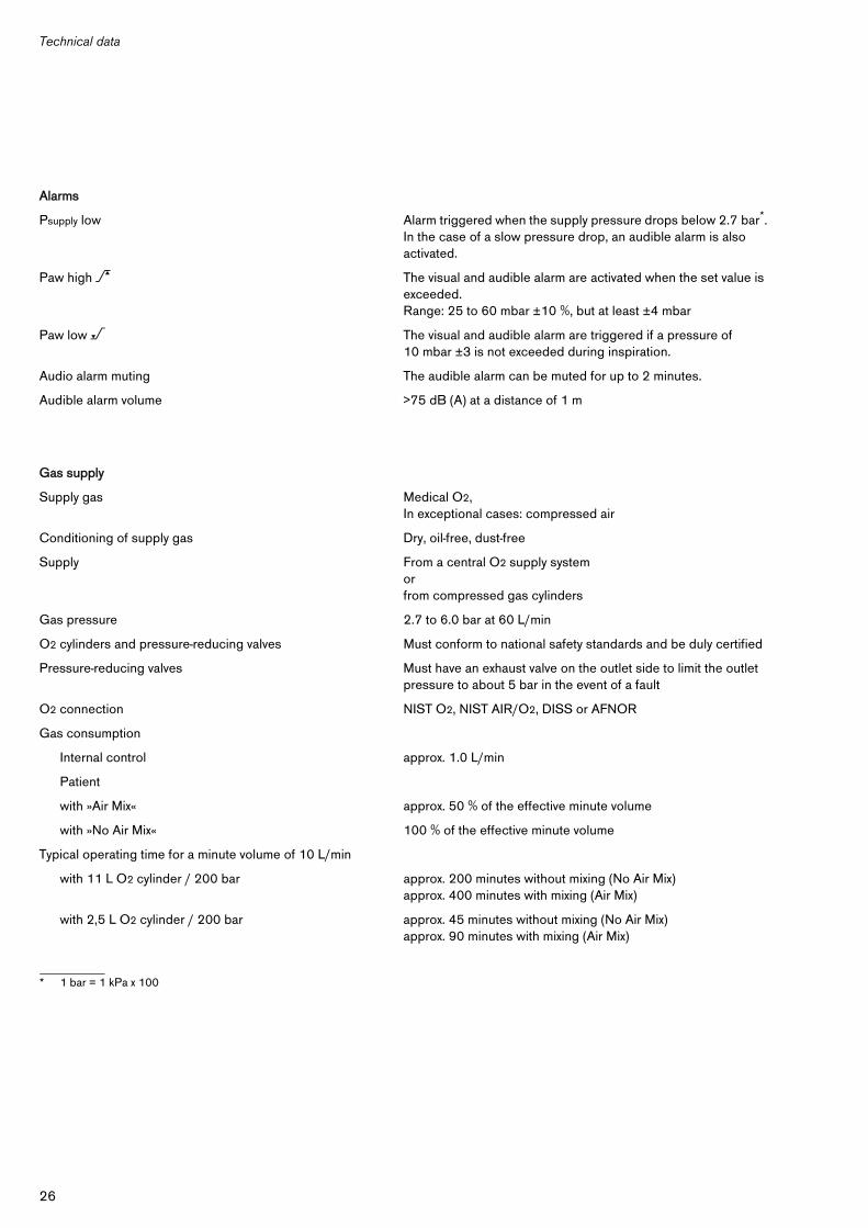
Psupply low Alarm triggered when the supply pressure drops below 2.7 bar*.In the case of a slow pressure drop, an audible alarm is also activated.
* 1 bar = 1 kPa x 100
Paw high > The visual and audible alarm are activated when the set value is exceeded. Range: 25 to 60 mbar ±10 %, but at least ±4 mbar
Paw low < The visual and audible alarm are triggered if a pressure of 10 mbar ±3 is not exceeded during inspiration.
Audio alarm muting The audible alarm can be muted for up to 2 minutes.
Audible alarm volume >75 dB (A) at a distance of 1 m
Gas supply
Supply gas Medical O2,In exceptional cases: compressed air
Conditioning of supply gas Dry, oil-free, dust-free
Supply From a central O2 supply systemorfrom compressed gas cylinders
Gas pressure 2.7 to 6.0 bar at 60 L/min
O2 cylinders and pressure-reducing valves Must conform to national safety standards and be duly certified
Pressure-reducing valves Must have an exhaust valve on the outlet side to limit the outlet pressure to about 5 bar in the event of a fault
O2 connection NIST O2, NIST AIR/O2, DISS or AFNOR
Gas consumption
Internal control approx. 1.0 L/min
Patient
with »Air Mix« approx. 50 % of the effective minute volume
with »No Air Mix« 100 % of the effective minute volume
Typical operating time for a minute volume of 10 L/min
with 11 L O2 cylinder / 200 bar approx. 200 minutes without mixing (No Air Mix)approx. 400 minutes with mixing (Air Mix)
with 2,5 L O2 cylinder / 200 bar approx. 45 minutes without mixing (No Air Mix)approx. 90 minutes with mixing (Air Mix)

27
Technical data
Abbreviations and symbols
Dimensions (W x H x D) mm 215 x 90 x 215 (without handle)
Weight
Oxylog 1000 (basic unit) 3.15 kg
Ventilation hose, reusable, 1.5 m 0.35 kg
Ventilation valve, reusable 0.06 kg
Single-use hose system(consisting of ventilation hose and ventilation valve)
0.11 kg
Materials used
Ventilator housing Impact-resistant acrylonitrile butadiene styrene (ABS)
Ventilation hose, reusable Silicone rubber
Ventilation valve housing, reusable Polysulphone (PSU), silicone rubber
Single-use hose system Silcone rubber, polycarbonate (PC), polypropylene (PP), ethylene vinylacetate (EVA)
Classificationaccording to Directive 93/42/EC, Appendix IX
Class IIb
UMDNS-CodeUniversal Medical Device Nomenclature System
18 – 098
Type of protection IPX4
Air Mix Mixing of O2 with ambient air, approx. 60 % O2 by vol.
IPPV Intermittent Positive Pressure Ventilation
Freq. Ventilation frequency, strokes per minute
MV Minute volume, L/min
No Air Mix No mixing with ambient air, 100 % O2 by volume
Paw Airway pressure
Paw > Upper alarm limit of airway pressure
Paw < Lower alarm limit of airway pressure
PEEP Positive End Exspiratory Pressure
Pmax Set point for upper alarm limit Paw
Psupply Supply pressure
H Setting symbol for ventilation rate and airway pressure during heart-lung resuscitation
g Audio alarm muting

Appendix
28
Appendix
Minute volume and O2 concentration as a function of airway pressure
Air Mix function
Oxylog 1000 supplies the air/O2 mixture (Air Mix) by means of an injector that draws in additional air from the atmosphere to generate an air/O2 mix with an O2 concentration of about 60 % by volume.Due to the laws of physics, the suction effect of injectors decreases with increasing back pressure.With high airway pressures, the minute volume MV set may be reduced during the Air Mix function, thereby increasing the O2 concentration.At airway pressures up to 20 mbar, the set and applied minute volume (MV) are the same. An additional increase of airway pressure by 10 mbar leads to a reduction of the volume applied by about 10 %. The set minute volume MV should possibly be increased appropriately. Since less air is drawn from the atmosphere when there is an increase in airway pressure, the O2 concentration increases. At a low minute volume MV of under 7 L/min, concentrations of up to 100 % by volume can be attained.
No Air Mix function
The applied minute volume MV is not a function of the airway pressure. The O2 concentration is always 100 %.
Minute volume as a function of ambient air pressure
The applied minute volume MV is also dependent on the atmospheric pressure of the surrounding area (reference value 1013 hPa). If the atmospheric pressure is reduced by 100 hPa, the supplied minute volume MV is increased by about 10 %.

29
Appendix
Block circuit diagram
Function description of the Oxylog 1000 with reference to the block circuit diagram
The supply gas, O2 (or compressed air), is channelled via the filter 1, the on/off switch 2 to the ventilation block 3, which can optionally be connected to the "Air Mix" module 4.The minute volume is set by the "MV" valve 5 and controls the ventilation block 3.The frequency is set by the "Freq." valve 6 and acts on the frequency control 7, which is coupled to the alarm logic system 8.The upper alarm limit "Pmax" is set with the "Pmax" rotary knob 9 and opens a valve in the ventilation block 3, so that the airway pressure is limited during inspiration.The alarm logic 8 is connected to the "audible alarm muting control" 10 by push-button »g« 11. When button »g« 11 is pressed, the yellow indicator »g« 12 is displayed, and the audible alarm is suppressed for up to 2 minutes. Additional relief valve 13 is permanently set and opens at a specified pressure of around 80þmbar.The emergency air valve 14 permits spontaneous breathing by the patient in the event of ventilator failure.
0432
9033
AirMix
MV
1 2 3 4
56
78
9
10
11
12
1413
Pmax Freq. MV

Order List
30
Order List
Name and description Part No.
Basic unit
Oxylog 1000Time-cycled, constant volume emergency ventilator with alarms for high and low airway pressure and low supply pressure
2M 86 105
Optional accessories
Caddy 57 03 300
Carrying system 1000 2M 86 001
Wall Holder for Carrying System 1000 2M 86 103
Spare bag for Carrying System 1000 AB 41 047
Vehicle bracket 84 12 069
Test lung 84 03 201
Ventilation hose E ISO, reusable, 1.5 m 2M 86 511
Ventilation hose E ISO, reusable, 3.0 m 21 12 760
Ventilation valve, reusable 2M 86 800
Reusable PEEP valve (0 to 10 mbar) 84 07 475
Single-use hose system (25 pieces)consisting of ventilation hose with ventilation valve
2M 86 837
Single-use PEEP valve (5 to 20 mbar) 2M 86 832
Connecting hoses
CG*-connecting hoses
* Central piped gas supply
Gas Supply System 57 04 500
31
Index
Index
AAbbreviations . . . . . . . . . . . . . . . . . . . . . . . . . . . . . . . . . . . . . 27Accessories . . . . . . . . . . . . . . . . . . . . . . . . . . . . . . . . . . . . . . . . 3Applications . . . . . . . . . . . . . . . . . . . . . . . . . . . . . . . . . . . . . . . . 4
BBefore using for the first time . . . . . . . . . . . . . . . . . . . . . . . . . 4CCentral O2 supply . . . . . . . . . . . . . . . . . . . . . . . . . . . . . . . . . 17Checking readiness for operation . . . . . . . . . . . . . . . . . . . 18Connection O2 supply . . . . . . . . . . . . . . . . . . . . . . . . . . . . . 16
DDefinitions . . . . . . . . . . . . . . . . . . . . . . . . . . . . . . . . . . . . . . . . . 3Device Check . . . . . . . . . . . . . . . . . . . . . . . . . . . . . . . . . . . . . . . 6Disinfecting/Cleaning . . . . . . . . . . . . . . . . . . . . . . . . . . . . . . 12Dismantling . . . . . . . . . . . . . . . . . . . . . . . . . . . . . . . . . . . . . . 11Disposing of the apparatus . . . . . . . . . . . . . . . . . . . . . . . . . 22Dräger Oxator, use of . . . . . . . . . . . . . . . . . . . . . . . . . . . . . . 17
EEnd of operation . . . . . . . . . . . . . . . . . . . . . . . . . . . . . . . . . . 10End-expiratory volume measurement . . . . . . . . . . . . . . . . . 10Environmental conditions . . . . . . . . . . . . . . . . . . . . . . . . . . . 25
FFront view . . . . . . . . . . . . . . . . . . . . . . . . . . . . . . . . . . . . . . . . 23
HHeart-lung resuscitation . . . . . . . . . . . . . . . . . . . . . . . . . . . . . . 9
IImmersion disinfecting . . . . . . . . . . . . . . . . . . . . . . . . . . . . . 13Installing the Oxylog 1000 . . . . . . . . . . . . . . . . . . . . . . . . . . 15Intended use . . . . . . . . . . . . . . . . . . . . . . . . . . . . . . . . . . . . . . . 4IPPV . . . . . . . . . . . . . . . . . . . . . . . . . . . . . . . . . . . . . . . . . . . . . . 7
MMaintenance intervals . . . . . . . . . . . . . . . . . . . . . . . . . . . . . . 22
OOperating concept . . . . . . . . . . . . . . . . . . . . . . . . . . . . . . . . . . 5Order List . . . . . . . . . . . . . . . . . . . . . . . . . . . . . . . . . . . . . . . . 30
PPEEP valve . . . . . . . . . . . . . . . . . . . . . . . . . . . . . . . . . . . . . . . 15Performance characteristics . . . . . . . . . . . . . . . . . . . . . . . . 25Pmax . . . . . . . . . . . . . . . . . . . . . . . . . . . . . . . . . . . . . . . . . . . . . . 8Precautions . . . . . . . . . . . . . . . . . . . . . . . . . . . . . . . . . . . . . . . . 4
SSide view . . . . . . . . . . . . . . . . . . . . . . . . . . . . . . . . . . . . . . . . 24Sterilising . . . . . . . . . . . . . . . . . . . . . . . . . . . . . . . . . . . . . . . . 13Symbols . . . . . . . . . . . . . . . . . . . . . . . . . . . . . . . . . . . . . . . . . 27
TTechnical data . . . . . . . . . . . . . . . . . . . . . . . . . . . . . . . . . . . . 25Test lung, connecting . . . . . . . . . . . . . . . . . . . . . . . . . . . . . . 18Testing the »Paw . . . . . . . . . . . . . . . . . . . . . . . . . . . . . . . . . . 19Testing the »Paw >« alarm . . . . . . . . . . . . . . . . . . . . . . . . . . 19Troubleshooting . . . . . . . . . . . . . . . . . . . . . . . . . . . . . . . . . . . 21
VVentilation valve, Dismantling . . . . . . . . . . . . . . . . . . . . . . . . 12Ventilation with a mask . . . . . . . . . . . . . . . . . . . . . . . . . . . . . . . 9Ventilation with PEEP . . . . . . . . . . . . . . . . . . . . . . . . . . . . . . . . 9
WWhat's what . . . . . . . . . . . . . . . . . . . . . . . . . . . . . . . . . . . . . . 23Wipe disinfecting . . . . . . . . . . . . . . . . . . . . . . . . . . . . . . . . . 13

Index
32
This page is intentionally left blank
Dräger Medical b.v.z Kanaaldijk 29
5683 CR BESTThe Netherlands
y +31 499 331 331FAX +31 499 331 333! [email protected]
www.draeger-medical.com
These Instructions for Use apply only toOxylog 1000with Serial No.:If no Serial No. has been filled in by Dräger these Instructions for Use are provided for general information only and are not intended for use with any specificmachine or device.
Directive 93/42/EECconcerning Medical Devices
0344
90 37 394 - 06 en - GA 5503.410 © Dräger Medical b.v.5th edition - January 2007Subject to alteration