Embed Size (px)
Citation preview

9/14/12 PN 96825 v.6.0
Banks Six-Gun®/EconoMind® & SpeedBrake®
For use with Banks iQ™
& compatible with PowerPDA
2003-07 Ford Power Stroke6.0L Turbo-Diesel THIS MANUAL IS FOR USE WITH SYSTEMS 55455-55458 & 63749
Gale Banks Engineering 546 Duggan Avenue • Azusa, cA 91702 (626) 969-9600 • Fax (626) 334-1743
Product Information & Sales: (888) 635-4565customer Support: (888) 839-5600 Installation Support: (888) 839-2700
bankspower.com
©2012 Gale Banks Engineering
Owner’sManualwith Installation Instructions
2 96825 v.6.0
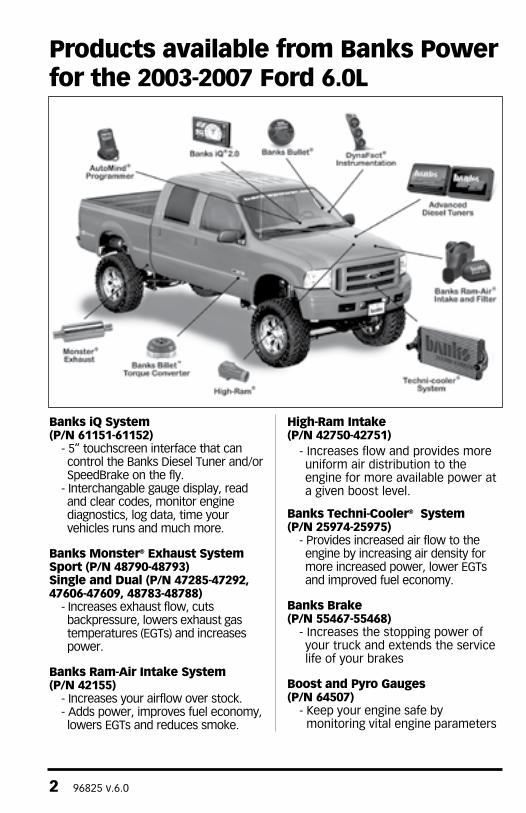
Banks iQ System(P/N 61151-61152)
- 5” touchscreen interface that can control the Banks Diesel Tuner and/or SpeedBrake on the fly.
- Interchangable gauge display, read and clear codes, monitor engine diagnostics, log data, time your vehicles runs and much more.
Banks Monster® Exhaust SystemSport (P/N 48790-48793)Single and Dual (P/N 47285-47292, 47606-47609, 48783-48788)
- Increases exhaust flow, cuts backpressure, lowers exhaust gas temperatures (EGTs) and increases power.
Banks Ram-Air Intake System(P/N 42155)
- Increases your airflow over stock. - Adds power, improves fuel economy, lowers EGTs and reduces smoke.
High-Ram Intake(P/N 42750-42751)
- Increases flow and provides more uniform air distribution to the engine for more available power at a given boost level.
Banks Techni-Cooler® System(P/N 25974-25975)
- Provides increased air flow to the engine by increasing air density for more increased power, lower EGTs and improved fuel economy.
Banks Brake(P/N 55467-55468)
- Increases the stopping power of your truck and extends the service life of your brakes
Boost and Pyro Gauges(P/N 64507)
- Keep your engine safe by monitoring vital engine parameters
Products available from Banks Power for the 2003-2007 Ford 6.0L

96825 v.6.0 3
For More Information please call (888) 635-4565or Visit us online @ www.bankspower.com
Banks Billet Torque Converter(P/N 72522)
- Higher torque capacity over stock- Lockup clutch is slip-resistant so transmission fluids stay cooler and transmission life is prolonged.
Banks SpeedBrakeiQ Compatible (P/N 55455-55456)PDA Compatible (P/N 55457-55458)
- Allows for controlled hill decent at a user defined vehicle speed.
Banks Bullet(P/N 66524-66525)
- Adds power safely to your vehicle - Displays critical engine functions - Engine safeguards - change power levels on-the-fly
Banks Diesel TunerSix-Gun w/ switch (P/N 61023)Six-Gun w/ iQ (P/N 63749)EconoMind w/ switch (P/N 63743-63745)EconoMind w/ iQ (P/N 63747-63748)
- Adds power safely to your vehicle- Engine and transmission safeguards- change power levels on-the-fly
Thermocouple- Add a temperature limiting function to your Diesel Tuner
AutoMind Programmer(P/N 66100)
- contains Banks tunes that boost your vehicles HP, Torque and MPG.
- Displays a host of critical engine functions
- Provides “service technician” diagnostic capabilities
- Has upgradeable functionality, so it will never be out of date
Banks Stinger Systems(P/N 46465-46486)Contains:
- Ram-Air Intake system- Monster Exhaust (single or dual)- EconoMind Tuner w/ Banks iQ
Banks PowerPack Systems(P/N 46497-46519)Contains:
- Ram-Air Intake system- Monster Exhaust (single or dual)- EconoMind Tuner w/ Banks iQ- High-Ram- Techni-cooler System
Banks Six-Gun Bundle(P/N 46594-46613)Contains:
- Ram-Air Intake system- Monster Exhaust (single or dual)- Six-Gun Tuner w/ Banks iQ
Banks Big Hoss Bundle(P/N 46623-46643)Contains:
- Ram-Air Intake system- Monster Exhaust (single or dual)- Six-Gun Tuner w/ Banks iQ- Big Head Wastegate Actuator- High-Ram- Techni-cooler System

4 96825 v.6.0
THIS IS A HIGH PERFORMANCE PRODUCT. USE AT YOUR OWN RISK.
Do not use this product until you have carefully read the following agreement.
This sets forth the terms and conditions for the use of this product. The installation of this product indicates that the BUYER has read and understands this agreement and accepts its terms and conditions.
Disclaimer of LiabilityGale Banks Engineering Inc., and its distributors, employees, and dealers (hereafter “SELLER”) shall in no way be responsible for the product’s proper use and service. The BUYER hereby waives all liability claims.
The BUYER acknowledges that he/she is not relying on the SELLER’s skill or judgment to select or furnish goods suitable for any particular purpose and that there are no liabilities which extended beyond the description on the face hereof and the BUYER hereby waives all remedies or liabilities, expressed or implied, arising by law or otherwise, (including without any obligations of the SELLER with respect to fitness, merchantability, and consequential damages) whether or not occasioned by the SELLER’s negligence.
The BUYER is responsible to fully understand the capability and limitations of his/her vehicle according to manufacturer specifications and agrees to hold the SELLER harmless from any damage resulting from the failure to adhere to such specifications.
The SELLER disclaims any warranty and expressly disclaims any liability for personal injury or damages. The BUYER acknowledges and agrees
that the disclaimer of any liability for personal injury is a material term for this agreement and the BUYER agrees to indemnify the SELLER and to hold the SELLER harmless from any claim related to the item of the equipment purchased. Under no circumstances will the SELLER be liable for any damages or expenses by reason of the use or sale of any such equipment.
The BUYER is responsible to obey all applicable federal, state, and local laws, statutes, and ordinances when operating his/her vehicle, and the BUYER agrees to hold SELLER harmless from any violation thereof.
The SELLER assumes no liability regarding the improper installation or misapplication of its products. It is the installer’s responsibility to check for proper installation and if in doubt, contact the manufacturer.
The BUYER is solely responsible for all warranty issues from the automotive manufacturer.
Limitation of WarrantyGale Banks Engineering Inc. (hereafter “SELLER”), gives Limited Warranty as to description, quality, merchantability, fitness for any particular purpose, productiveness, or any other matter of SELLER’s product sold herewith. The SELLER shall be in no way responsible for the product’s open use and service and the BUYER hereby waives all rights except those expressly written herein. This Warranty shall not be extended or varied except by written instrument signed by SELLER and BUYER.
Please see enclosed warranty information card, or go to www.bankspower.com/warranty, for warranty information regarding your product.. All products that are in question of Warranty must be returned shipping prepaid to the SELLER and

96825 v.6.0 5
must be accompanied by a dated proof of purchase receipt. All Warranty claims are subject to approval by Gale Banks Engineering Inc.
Under no circumstance shall the SELLER be liable for any labor charged or travel time incurred in diagnosis for defects, removal, or reinstallation of this product, or any other contingent expense.
WARNING: Below 32oF (0oC) or above 140oF (60oC), the Banks iQ may be susceptible to damage as a result of extended direct exposure to sunlight, heat or extreme cold. It is highly recommended that Banks iQ be removed from its mounting location if the vehicle will be subjected to high concentrations of sunlight, heat or cold for an extended period of time. Gale Banks Engineering is not responsible for damage to Banks iQ resulting from exposure conditions.
Under no circumstances will the SELLER be liable for any damage or expenses incurred by reason of the use or sale of any such equipment.
In the event that the buyer does not agree with this agreement:
The buyer may promptly return this product, in a new and unused condition, with a dated proof-of-purchase, to the place-of-purchase within thirty (30) days from date-of-purchase for a full refund, less shipping and/or restocking fee.
The installation of this product indicates that the buyer has read and understands this agreement and accepts its terms and conditions.
Table of Contents
General Installation Practices . . . . 7
Section 1 . . . . . . . . . . . . . . . . . . . . . . 8Installation of Wiring Harness for Banks Six-Gun/EconoMind Diesel Tuner
Section 2 . . . . . . . . . . . . . . . . . . . . . 18Installation of Wiring Harness, for Optional Banks SpeedBrake
Section 3 . . . . . . . . . . . . . . . . . . . . . 25Mounting and connecting the Banks iQ
Section 4 . . . . . . . . . . . . . . . . . . . . . 30Optional Thermocouple Installation (Required for Banks iQ)
Section 5 . . . . . . . . . . . . . . . . . . . . . 32Automatic Transmission Learning
Section 6 . . . . . . . . . . . . . . . . . . . . . 33checking Engine Performance
Section 7 . . . . . . . . . . . . . . . . . . . . . 34Troubleshooting
Section 8 . . . . . . . . . . . . . . . . . . . . . 39clearing Learned Information
Section 9 . . . . . . . . . . . . . . . . . . . . . 39Removal of the Six-Gun/EconoMind Diesel Tuner
Section 10 . . . . . . . . . . . . . . . . . . . . 40Updating Banks iQ/PowerPDA & Banks Six-Gun/EconoMind/SpeedBrake Software
Section 11 . . . . . . . . . . . . . . . . . . . . 41Placement of the Banks Power Decals
For detailed operation of the Banks SpeedBrake functions, refer to the Banks iQ manual.

6 96825 v.6.0
The Banks Six-Gun/EconoMind Diesel Tuner has six power levels that you can adjust with the Banks iQ Dashboard Pc
Banks iQ is a versatile device that gives you total control of your Banks Six-Gun/EconoMind Tuner. With a touch of your finger on the bright, full-color LCD display, you can adjust power levels on-the-fly, customize the gauges you view, tune numerous performance parameters, set system warnings and alerts, see vital engine functions at a glance, and more. Evaluate your changes by running 0-60, ¼ and 1/8 mile performance tests. You can even scan, read and clear OBDII diagnostic trouble codes.
Banks iQ doesn’t stop there. It’s a true in-car PC packed full of extra functions. Listen to your favorite tunes, watch videos, play games, review Windows® Office documents, and more. Expandable and upgradeable, it comes fitted with a rechargeable battery and includes accessory cords. You’ll quickly discover Banks iQ is the device you’ll use every day, both inside and outside your car.
Level 1 is stock. Each additional higher level adds approximately 20% of the available power increase.To prevent damage to the factory transmission, Banks recommends that both automatic and manual transmission vehicles do not exceed Level 4 while the vehicle is experiencing load (towing, climbing a steep grade, carrying a load, etc.).
To use the higher levels of the Six-Gun/EconoMind Diesel Tuner while towing or climbing, airflow improvements must be made to lower the exhaust gas temperature (EGT) entering the turbo. The EGT should not exceed 1400º F for more than a few seconds. Elevated EGT can damage the turbocharger and the engine.
ATTENTION!Before proceeding with these instructions, please carefully read the DISCLAIMER OF LIABILITY and LIMITATION OF WARRANTY statement located on page 4 of this manual.
WARNING: Banks iQ may be susceptible to damage as a result of extended exposure to sunlight, heat or extreme cold. It is highly recommended that Banks iQ be removed from its mounting location if the vehicle will be subjected to high concentrations of sunlight, heat or cold for an extended period of time. Gale Banks Engineering is not responsible for damage to Banks iQ resulting from exposure conditions.
Dear Customer,
If you have any questions concerning the installation of your Banks Six-Gun/EconoMind Diesel Tuner, please call our Technical Service Hotline at (888) 839-2700 between 7:00am and 5:00pm (PST). If you have any questions relating to shipping or billing, please contact our Customer Service Department at (888) 839-5600.
Thank you.

96825 v.6.0 7
TOOLS REQUIRED:
• Inch and metric sockets• Inch and metric combination and open-end wrenches• Pliers• Ford stereo removal tool (’03-04 model year vehicles only)• Wire cutters• Scissors• Drill motor• 1⁄8” drill bit• 13⁄32” drill bit• 7⁄16” drill bit• Tap handle• 1⁄4” NPT tap • Foot-pound torque wrenches• Penetrating oil or light lubricant spray• Anti-seize compound• Heat gun
1. Before starting work, familiarize yourself with the installation procedure by reading all of the instructions.
2. The exploded views provide only general guidance. Refer to each step and section diagram in this manual for proper instruction.
3. Throughout this manual, the left side of the vehicle refers to the driver side, and the right side to the passenger side.
4. Disconnect the negative (ground) cable from the battery (or batteries, if there are two) before beginning work.
5. Route and tie wires and hoses a minimum of 6” away from exhaust heat, moving parts and sharp edges. clearance of 8” or more is recommended where possible.
6. When raising the vehicle, support it on properly weight-rated safety stands, ramps or a commercial hoist.
Follow the manufacturer’s safety precautions. Take care to balance the vehicle to prevent it from slipping or falling. When using ramps, be sure the front wheels are centered squarely on the topsides. When raising the front of the vehicle, put the transmission in park (automatic) or reverse (manual), set the parking brake, and block the rear wheels. When raising the back of the vehicle, be sure the vehicle is on level ground and the front wheels are blocked securely.
CAUTION: Do not use floor jacks to support the vehicle while working under it. Do not raise the vehicle onto concrete blocks, masonry or any other item not intended specifically for this use.
7. During installation, keep the work area clean. Do not allow anything to be dropped into intake, exhaust, or lubrication system components while performing the installation, as foreign objects will cause immediate engine damage upon start-up.
8. Save this Owner’s Manual as a reference for system maintenance and service.
9. Banks recommends either a Banks IQ or a Pyrometer (EGT) gauge and Boost gauge be installed with the Six-Gun/EconoMind Diesel Tuner to help monitor performance and exhaust gas temperature of the vehicle (see part numbers next page). To further increase engine life by lower EGT’s, Banks also recommends installing a Monster Exhaust® system (see next page).
General Installation Practices

8 96825 v.6.0
Figure 1: Six-Gun/EconoMind and supplied wiring harnesses (Six-Gun shown)
Banks iQ System .....................61152
Banks Monster® Exhaust:
‘03 F-250/350 Pickup Ext cab, short bed .......................48764‘04-07 F-250/350 Pickup Ext cab, short bed .......................48784‘03 F-250/350 Pickup Ext cab, long bed ........................48766‘04-07 F-250/350 Pickup Ext cab, long bed ........................48786‘03 F-250/350 Pickup Crew cab, short bed ...................48765‘04-07 F-250/350 Pickup Crew cab, short bed ...................48785‘03 F-250/350 Pickup Crew cab, long bed .....................48767‘04-07 F-250/350 Pickup Crew cab, long bed ....................48787‘03 Excursion ...............................48768‘04-07 Excursion .........................48788
Additional Equipment: Technicooler® (‘03-04) .....................25974 Technicooler® (‘05-07) .....................25975 Gauge Assembly, Boost and Pyro .......................... .64507 Thermocouple ............................63055

96825 v.6.0 9
If Banks Six-Gun/EconoMind has been previously installed, skip to Section 2.
If installing Banks Six-Gun/EconoMind for the first time, proceed to step 1
1. Disconnect the battery ground cables from each of the batteries. Secure the cables so that they do not come in contact with the battery posts during the installation.
2. Remove the (+) battery cable from the driver side battery.
3. Remove the driver side plastic battery cover, as shown in Figure 2. This is accomplished by depressing a tab at the front and rear of the cover. Be careful not to damage the cover, as it will be re-installed.
4. Remove the driver side battery hold down clamp (8mm socket). Remove the driver side battery.
WARNING: When lifting a battery, excessive pressure on the end
walls could cause acid to spew through the vent caps, resulting in personal injury. Lift with a battery carrier or with hands on opposite corners. Failure to follow these instructions may result in personal injury.
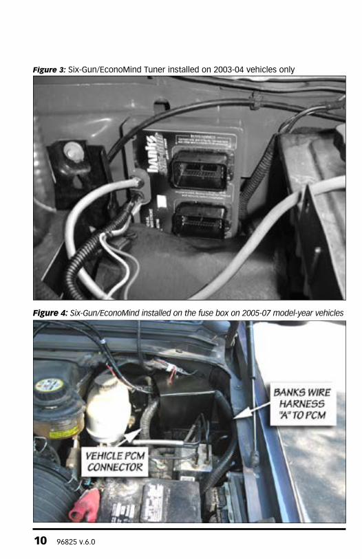
5. Place the Six-Gun/EconoMind Diesel Tuner in close proximity as shown in Figure 3 for 2003-04 and Figure 4 for 2005-07. The ‘In-cab cable’ with the three small connectors will be routed into the cabin via the grommet on the firewall. The MAP sensor harness with the two connectors will be routed via the firewall to its prospective location listed in the following steps.
NotE: (the Six-Gun/EconoMind Diesel tuner will be affixed to its permanent location in step 20.)
6. Locate the Powertrain control Module (PcM) on the driver side of the vehicle engine compartment (see Figure 5).
Section 1INSTALLATION OF WIRING HARNESS AND CONNECTIONS FOR BANKS SIx-GUN/ECONOMIND DIESEL TUNER
Figure 2: Removal of the battery box cover
10 96825 v.6.0
Figure 3: Six-Gun/EconoMind Tuner installed on 2003-04 vehicles only
Figure 4: Six-Gun/EconoMind installed on the fuse box on 2005-07 model-year vehicles

96825 v.6.0 11
7. Disconnect the middle connector from the PcM by opening the overcenter retaining clamp as shown in Figure 5. Route the disconnected PCM connector to the Six-Gun/EconoMind Diesel Tuner as directed below:
2003-04 model year vehicles: Route the previously disconnected middle connector under the power steering fluid reservoir towards the Six-Gun/EconoMind Diesel Tuner.
2005-07 model year vehicles: Route the previously disconnected middle connector in the most direct path towards the Six-Gun/EconoMind Diesel Tuner.
8. All Years: Plug the PcM connector into the connector on the Six-Gun/EconoMind Diesel Tuner labeled, ”VEHIcLE HARNESS”.
9. Locate the supplied ‘crossover Cable’ wiring harness in your Six-Gun/EconoMind tuner kit.
10. Plug the supplied ‘crossover Cable’ wiring harness into the Six-Gun/EconoMind Diesel Tuner connector labeled, “BANKS HARNESS.”
For 2005-2007 Model vehicles: Slide Six-Gun/EconoMind Shield onto crossover cable.
NotE: Be sure that the seam on the top of the shield is facing away from the cabin (see Figure 6).For all models, route the other end of the ‘crossover cable’ to the vehicle’s PcM middle connector labeled “c”. Route the ‘crossover cable’ as directed below:
2003-04 model year vehicles: Route the ‘crossover cable’ under the power steering fluid reservoir.
2005-07 model year vehicles: Route the ‘crossover cable’ to the PcM in the most direct path possible.
11. All Years: Plug the ‘crossover cable’ into the vehicle’s PcM middle connector labeled “c”.
Figure 5: View of the PCM after the battery cover has been removed

12 96825 v.6.0
12. Unplug the Manifold Absolute Pressure (MAP) sensor connector shown in Figure 7. The MAP connector can be unplugged by sliding the red safety slide down, pressing the locking button, then pulling on the connector.
13. Plug the Six-Gun/EconoMind MAP connector into the MAP sensor. Plug the factory MAP connector into the Six-Gun/EconoMind MAP wiring harness. Route the harness from the Six-Gun/EconoMind to the MAP sensor as shown in Figure 8. Use the supplied zip ties to secure the MAP harness to the factory harness.
Failure to follow the recommended harness routing may result in a melted harness.14. Route the Six-Gun/EconoMind ‘In-cab cable’ through the firewall to the passenger compartment. When passing through the firewall, either make a hole in a factory grommet or drill a hole and use a new grommet. If drilling, check the backside to make sure there are no components that may be damaged by drilling.
15. Remove the lower driver side interior panel that allows access to the fuse box.
16. From inside the vehicle, continue to pull the cable through the firewall until it is approximately 22” inside the cab. Secure the cable to the lower access panel area. Take precaution to leave the three connectors accessible for usage further in the installation process.
If Banks SpeedBrake is being installed, ignore steps 17-19 and proceed to step 20.
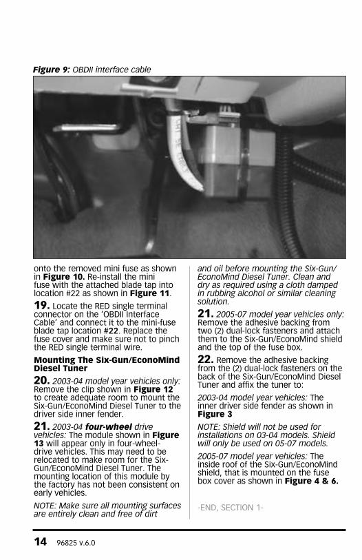
17. Locate the ‘OBDII Interface cable’ in your kit. connect the ‘OBDII Interface cable’ to the vehicle OBDII connector. Use the large cable tie in your kit as shown in Figure 9 to secure the ‘OBDII Interface cable’ to the vehicle OBDII connector.
Now, connect the 8-pin connector from the ‘OBDII Interface cable’ to the 8-pin connector on the Six-Gun/EconoMind ‘In-cab cable.’
NotE: If you are not installing the optional Banks iQ then coil up and secure cable with the RJ12 (telephone style) connector end.
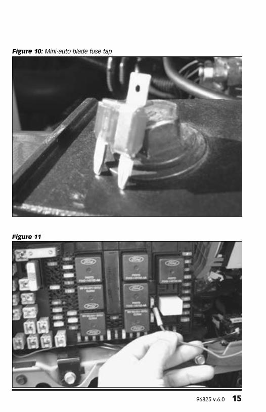
18. Remove the fuse box cover, located in the cabin compartment. Locate the mini-fuse #22 and remove. Install the mini-auto blade fuse tap
Figure 6: (2005-07 model year vehicles only) tuner Mounting

96825 v.6.0 13
Figure 7: MAP sensor location
Figure 8: MAP sensor harness routing
14 96825 v.6.0
onto the removed mini fuse as shown in Figure 10. Re-install the mini fuse with the attached blade tap into location #22 as shown in Figure 11.
19. Locate the RED single terminal connector on the ‘OBDII Interface cable’ and connect it to the mini-fuse blade tap location #22. Replace the fuse cover and make sure not to pinch the RED single terminal wire.
Mounting The Six-Gun/EconoMind Diesel Tuner
20. 2003-04 model year vehicles only: Remove the clip shown in Figure 12 to create adequate room to mount the Six-Gun/EconoMind Diesel Tuner to the driver side inner fender.
21. 2003-04 four-wheel drive vehicles: The module shown in Figure 13 will appear only in four-wheel-drive vehicles. This may need to be relocated to make room for the Six-Gun/EconoMind Diesel Tuner. The mounting location of this module by the factory has not been consistent on early vehicles.
NotE: Make sure all mounting surfaces are entirely clean and free of dirt
and oil before mounting the Six-Gun/EconoMind Diesel tuner. Clean and dry as required using a cloth damped in rubbing alcohol or similar cleaning solution.
21. 2005-07 model year vehicles only: Remove the adhesive backing from two (2) dual-lock fasteners and attach them to the Six-Gun/EconoMind shield and the top of the fuse box.
22. Remove the adhesive backing from the (2) dual-lock fasteners on the back of the Six-Gun/EconoMind Diesel Tuner and affix the tuner to:
2003-04 model year vehicles: The inner driver side fender as shown in Figure 3
NotE: Shield will not be used for installations on 03-04 models. Shield will only be used on 05-07 models.
2005-07 model year vehicles: The inside roof of the Six-Gun/EconoMind shield, that is mounted on the fuse box cover as shown in Figure 4 & 6.
-END, SECTION 1-
Figure 9: oBDII interface cable
96825 v.6.0 15
Figure 10: Mini-auto blade fuse tap
Figure 11

16 96825 v.6.0
Figure 13
Figure 12: Removal of hood latch cable clip (2003-04 model year vehicles only)

96825 v.6.0 17
Figure 14 Banks SpeedBrake Wire Harnesses
If installing Banks SpeedBrake, proceed to step 1.
If an existing Six-Gun/EconoMind Tuner has been previously installed, verify that the Tuner has the latest version firmware. Check and compare to the current version available on the Banks website. Banks Brake may not function properly if Six-Gun/EconoMind Tuner firmware is not up to the current version. If the Tuner is not to the latest version refer to section 10.
If not installing Banks SpeedBrake, skip to Section 3.
1. Remove the fuse access panel below the steering column as shown in Figure 15.
2. Remove the fuse box cover, located in the cabin compartment.
If Six-Gun/EconoMind was previously installed, continue to step 3.
If Six-Gun/EconoMind was not previously installed, skip to step 8.
Removing a Previously Installed Banks OBD II Interface Cable
3. Locate the RED single terminal connector on the Banks ‘OBDII Interface cable’ and disconnect it from the mini-fuse blade tap location #22 if already connected. DO NOT remove the mini-fuse blade tap as it will be used for the Banks SpeedBrake wire harness installation. See Figure 16.
4. Disconnect Banks OBD II interface cable from the vehicle OBD II connector.
5. Disconnect the 8-pin connector from the OBD II interface cable from the 8-pin connector on the Six-Gun/EconoMind in-cab cable.
Section 2INSTALLATION OF WIRING HARNESS & CONNECTIONS FOR OPTIONAL BANKS SPEEDBRAKE

18 96825 v.6.0
Figure 15 Ford (’05-’07)
Figure 16

96825 v.6.0 19
Figure 17 Brake Pressure Sensor
6. Disconnecting the RJ12 cable.
A) For installed PowerPDA: Disconnect RJ12 from docking station.
B) For installed Banks iQ: Disconnect RJ12 from bridge module.
7. Remove the OBD II interface cable from the vehicle.
Installing Banks SpeedBrake Wire Harness
8. From inside the engine compartment, locate the factory brake pressure sensor connector on the brake master cylinder. The brake pressure sensor will be the connector farthest away from the firewall. See Figure 17. Disconnect the factory brake pressure sensor connector.
9. Locate the Brake Pressure Sensor harness in your kit. connect the female connector on the Brake Pressure Sensor harness to the factory male connector. connect the male connector on the Brake Pressure Sensor harness to the factory female connector.
10. Route the 2-pin connector on the Brake Pressure Sensor harness following the Six-Gun/EconoMind in-cab cable through the fire wall. Secure the wiring harness with the supplied cable ties away from any heat source or moving parts.
11. From under the dash, pull the 2-pin connector on the Brake Pressure Sensor harness through the fire wall.
12. Locate the Banks SpeedBrake Wire Harness and connect the 2-pin male connector on the Brake Pressure Sensor harness to the 2-pin connector on the Banks SpeedBrake wire harness.
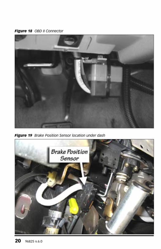
13. connect the Banks SpeedBrake Wire Harness OBD II connector to the vehicle’s OBD II connector. Use a cable tie, as shown in Figure 18 to secure the Banks SpeedBrake Wire Harness to the vehicle’s OBD II connector.
14. Locate the Fuse connector on the Banks SpeedBrake Wire Harness and connect it to the mini-fuse blade tap location #22. Replace the fuse cover and make sure not to pinch the Fuse wire.
20 96825 v.6.0
Figure 18 oBD II Connector
Figure 19 Brake Position Sensor location under dash

96825 v.6.0 21
Figure 20 Remove column panel covers
15. Now, connect the 8-pin connector from the Banks SpeedBrake Wire Harness to the 8-pin connector on the Six-Gun/EconoMind In-Cab Cable.
16. Locate the Foot Brake position switch connector under the dash. See Figure 19. Disconnect the foot brake position switch connector.
17. Locate the Brake Position Switch intercept connectors on the Banks SpeedBrake Wire Harness. connect the female connector on the Brake Position Switch intercept connectors to the factory black brake position switch connector. connect the male connector on the Brake Position Switch intercept connectors to the factory female brake position connector that was disconnected.
18. From under the steering column, remove the three (3) screws that hold the steering column panel covers in place. See Figure 20.
19. Using a standard screw driver remove the plastic ignition key guide. See Figure 21.
20. Move the steering column down to the lowest possible position to aid in removal of the top steering column
panel. Remove the top steering column panel.
CAUTION: Be careful when removing the top steering column panel or damage may result.
21. Locate the tow haul connector under the main wire harness towards the top rear of the steering column. See Figure 22.
22. Disconnect the tow haul connector.
23. Locate the tow haul intercept connector on the Banks SpeedBrake Wire harness. Route the Tow Haul intercept connectors under the dash towards the front of the vehicle and up to the top of the steering column following the factory harness to the factory tow haul connector. Make sure the connectors and wires are free of rotation from the steering column. connect the female connector on the Tow Haul intercept connectors to the factory male tow haul connector. connect the male connector on the Tow Haul intercept connectors to the factory female tow haul connector. Secure the connectors and wires with supplied cable ties.

22 96825 v.6.0
Figure 21 Remove Plastic Ignition Key Guide
Figure 22 tow Haul Connector on steering column, under main harness

96825 v.6.0 23
Figure 23 SpeedBrake Module Mounting Location
24. connect the Banks SpeedBrake module 10-pin connector on the Banks SpeedBrake wire harness to the SpeedBrake module. The connector will be the only one with a label.
NotE: Make sure the correct connection is made to the tuner and the Banks SpeedBrake module before proceeding.
25. Remove the adhesive backing from the dual-lock fasteners on the back of the SpeedBrake Module and attach the module to the location shown in Figure 23. Apply light pressure to the SpeedBrake Module by hand for 60-seconds to create a strong bond between the steering column surface and hook & loop interlocking fasteners. Using the supplied cable ties, secure the Banks SpeedBrake module wire harness away from any moving components.
NotE: Make sure all mounting surfaces are entirely clean and free of dirt and oil before mounting the SpeedBrake module. Clean and dry as required
using a cloth damped in rubbing alcohol or similar cleaning solution.
26. Install the top steering column panel back in place.
27. Reinstall the plastic key guide into place. Make sure it is snapped into place.
28. Reinstall the three (3) factory screws to fasten the steering column plans back together.
29. The RJ12 connector (phone like connector) on the Banks SpeedBrake Wire harness will be connected in Section 3, step 7 or 10. Leave this wire loose.
30. Go over all connection. Secure the wire harness with the supplied ties under the dash.
WARNING: Take care to keep any cables away from the pedals or where they could become tangled.
-END, SECTION 2-

24 96825 v.6.0
If installing a Banks SpeedBrake with a PowerPDA. Proceed to step 7.
WARNING: Below 32oF (0oC) or above 140oF (60oC), the Banks iQ may be susceptible to damage as a result of extended direct exposure to sunlight, heat or extreme cold. It is highly recommended that the Banks iQ be removed from its mounting location if the vehicle will be subjected to high concentrations of sunlight, heat or cold for an extended period of time. Gale Banks Engineering is not responsible for damage to Banks iQ resulting from exposure conditions.
CAUTION: Do not use force when working on plastic parts. Permanent damage to the part might result.
1. Locate the Window Mount Assembly in your kit.
2. Assemble the Banks iQ docking station to the Universal mount by
inserting and sliding the Universal mount tab into the docking station groove. Hand tighten the nut behind the docking station to hold the docking station in place.
3. Attach the window mount to your Banks iQ. See Figure 24. Align and place the two (2) lower tabs on the window mount to the corresponding slots on the bottom of Banks iQ first then snap the top of Banks iQ into place.
NotE: there may be a snug fit when installing the Banks iQ into the window mount. take care not to force this process.
4. Find a suitable place on the windshield for ease of access and viewing of Banks iQ. Use location shown in Figure 25 as a reference for mounting Banks iQ in your vehicle. Loosen the knob and move the swivel suction plate to achieve desired viewing angle of the Banks iQ screen. Do a test fit and note the angle necessary to achieve the correct viewing angle.
Section 3MOUNTING AND CONNECTING THE BANKS iQ
Figure 24 Attaching Banks iQ to window mount

96825 v.6.0 25
Figure 25 Suggested mounting location for Banks iQ
Figure 26 Ford (’05-’07)

26 96825 v.6.0
Figure 27
5. Make sure the suction cup and the mounting area on the windshield are clean and dry. With the suction lever in the up position, ensure the suction cup is flat against the windshield, and then push the suction lever down to secure in place.
6. Next, remove and set the fuse access panel aside. See Figure 26.
NotE: For 03-04 models the fuse access panel is held in place by four 1/4-turn plastic screws.
If applicable, remove the side access panel to help route wiring to the top of the dash. See Figure 27.
If installing a Banks SpeedBrake with a PowerPDA or Banks iQ. Use step 7 and skip steps 8-10.
If not installing SpeedBrake with an iQ. Use steps 8-10 and skip step 7.
7. RJ Connector with SpeedBrake
Banks iQ: Locate Banks iQ Bridge Module and connect the RJ12 connector from the Banks SpeedBrake wire Harness into the Bridge Module. See Figure 29.
PowerPDA: connect the RJ12 connector from the Banks SpeedBrake wire Harness into the leftmost receptacle on the bottom of the Docking Station.
Skip steps 8-12 if installing a SpeedBrake with a PowerPDA.
8. Locate the Banks OBD II Interface cable in your kit. This cable has three connection points. connect the RED OBD II connector on the Banks interface cable to the vehicle OBD II connector. Use a cable tie as shown in Figure 18 to secure the Banks interface cable to the vehicle

96825 v.6.0 27
Figure 28 Banks iQ System
OBD II connector. Next, connect the 6-pin connector on the Banks OBD II interface cable to the 6-pin connector on the Six-Gun/EconoMind Tuner harness.
9. Locate the RJ12 cable (similar to telephone connector) on your Banks OBDII interface cable. See Figure 28.
10. RJ12 Connector without SpeedBrake Banks iQ: Locate Banks iQ Bridge Module and connect the RJ12 connector into the Bridge Module. See Figure 29.
11. Route the Banks iQ USB interface cable from the Banks iQ Bridge Module under the dash and out through the side access panel opening. The cable can be slid under the door frame’s seal and run up to the top of the dash. Pull enough cable to reach the Banks iQ and connect it to the USB receptacle
on the left side of Banks iQ. See Figure 25. Snap the side access panel back in place making sure not to pinch the wire.
WARNING: THE CHARGING CABLE CONNECTED TO THE BANKS iQ IS DESIGNED TO SUPPLY A CONSTANT LOW-VOLTAGE POWER SOURCE (+5VDC) TO THE BANKS iQ AND IS “LIVE” AS LONG AS THE SYSTEM’S OBD II INTERFACE CABLE OR BANKS WIRING HARNESS IS COMPLETELY INSTALLED AND THE USB CABLE CONNECTOR IS PLUGGED INTO BANKS iQ. ALTHOUGH THIS CHARGING CABLE IS SHORT AND ITS CIRCUITRY IS FUSE-PROTECTED, THE USER IS ExPECTED TO TAKE APPROPRIATE MEASURES TO PREVENT SMALL CHILDREN AND/OR PETS FROM CONTACT WITH ANY PART OF THIS SYSTEM.

28 96825 v.6.0
Figure 29 Banks Bridge Module
12. Secure Banks iQ Bridge Module under the dash to any dash frame support using the supplied cable ties. Use the cable tie support loops on the side of the Bridge Module to securely fasten it under the dash.
13. Route all wiring away from any pedals or other moving components. Using the cable ties supplied, secure the wiring under the dash.
14. Reinstall the lower fuse access panel back in place with the factory hardware. Tuck any excess cable behind it for a clean appearance.
-END, SECTION 3-

96825 v.6.0 29
If not installing the Optional Thermocouple, skip to Section 5
1. The thermocouple monitors the temperature of the exhaust gases entering the turbocharger at the turbine housing. Installation requires that the exhaust manifold be drilled near the manifold outlet. It is recommended that the manifold be removed from the engine to thoroughly clean out all metal chips from drilling. All metal shavings must be cleaned from the manifold to avoid turbine wheel damage and possible interference with the turbocharger’s variable geometry turbine stage.
2. Disconnect the Exhaust Back Pressure Sensor tap located at the front of the driver side manifold. The pressure tap must be removed by using a 9⁄16” open-end wrench to hold the fitting stationary, and loosen the tube using a 5⁄8” open-end wrench. The fitting is shown in Figure 30.
NotE: Failure to hold the fitting stationary will damage the tube upon removal.
3. Remove the driver side exhaust manifold.
4. Drill a 7⁄16” hole in the driver side exhaust manifold at the location shown in Figure 31.
5. Tap the hole for a 1⁄4” NPT thread. check the thread depth as you tap by periodically removing the tap and screwing the pipe coupling into the tapped hole. The coupling should thread in 3 to 31⁄2 turns hand tight. Do not install the probe in place at this time.
CAUTION: Running the tap too deeply can prevent the pipe fitting from properly sealing.
6. Remove the NPT fitting from the thermocouple and install it on the exhaust manifold. Use anti-seize lubricant on the threads and torque to 14–16 lb-ft.
7. Remove all metal chips from the exhaust manifold.
NotE: Failure to remove all metal chips could result in catastrophic damage to the turbocharger’s turbine wheel or interfere with the operation of the variable geometry vane mechanism.
8. Re-install the exhaust manifold. Apply anti-seize lubricant to the
Section 4OPTIONAL THERMOCOUPLE INSTALLATION (REQUIRED FOR BANKS iQ)
Figure 30: Location of the static exhaust pressure line tap

30 96825 v.6.0
manifold bolt threads and torque to 28 lb-ft. Use the tightening sequence shown in Figure 32.
9. Tighten the turbocharger adapter pipe fasteners to 20 lb-ft as shown in Figure 33.
10. Reconnect the Exhaust Back Pressure Sensor tap.
11. connect the thermocouple wires to the Six-Gun/EconoMind Diesel Tuner with the supplied screws. The YELLOW thermocouple wire attaches to the free YELLOW wire on the Six-Gun/EconoMind Diesel Tuner. The RED thermocouple wire attaches to the free RED wire on the Six-Gun/EconoMind Diesel Tuner.
12. Slide the heat shrink over the exposed metal junction, and supply
moderate heat to seal the connection. A heat gun works well.
13. Route the thermocouple to the exhaust manifold and install the thermocouple in the fitting.
14. Reconnect the ground cables to the vehicles batteries.
Note: once the Six-Gun/econoMind Diesel tuner is powered up at key-on, it will ‘learn’ that a thermocouple is installed. If the thermocouple is removed after being installed and run on the vehicle, the Six-Gun/EconoMind Diesel tuner will assume that the sensor or connection has gone bad, and cease adding power while triggering the [2,3] diagnostic code (see trouble Shooting Section 7).
-END, SECTION 4-
Figure 31: Location to drill and tap the driver side exhaust manifold for the thermocouple
Figure 32: Exhaust manifoldtightening sequence
Figure 33: turbocharger adapter pipe torque specification

96825 v.6.0 31
Section 5AUTOMATIC TRANSMISSION LEARNING
The 6.0L Ford Trucks equipped with the TorqShiftTM 5-speed automatic overdrive transmission use an adaptive shift control logic. This will require the transmission to learn how to cope with the additional power created by the Banks Power products before it will shift properly. Additionally, the Banks Six-Gun/EconoMind Diesel Tuner will require a short learning curve to characterize the transmission in order to optimize fueling during gear change events. The following sequence must be followed to allow for collaborative learning between the Banks Six-Gun/EconoMind and the transmission’s control system. Failure to follow the sequence can result in damage to the transmission. Perform the following sequence at a location where it is safe to accelerate to 60 mph without exceeding the posted speed limit.
1. Start the truck and allow the engine to reach normal operating temperature.
2. Set the Banks iQ to power level 2.
3. Accelerate with the pedal to the floor, from a standing start to 60 mph. Repeat three (3) times.
4. Cruise at 30 mph, then press the accelerator to the floor to cause the transmission to downshift. continue accelerating to 60 mph.
5. Repeat steps (2) and (3) for the next power setting.
6. continue to increase the power setting and drive cycle until the desired power setting is achieved.
the torqShift™ 5-speed automatic transmission will continually adapt to the power output of the engine to optimize shift quality. this will result in the transmission un-learning how to cope with the higher power settings of the Six-Gun/EconoMind Diesel tuner, if the Six-Gun/EconoMind Diesel tuner is returned to a lower power setting. the rate that the transmission un-learns how to cope with the higher power levels, when switching to a lower power level, depends on the driving cycle. the transmission will quickly adapt to the power setting if the driving cycle includes regular gear changes at high loads. the transmission learning procedure will need to be repeated when switching back to the higher power settings once the transmission adapts to the lower power settings. It will be apparent when the transmission adapts to the lower settings by monitoring the feel of the gearshift. Gear changes will be noticeably harder when initially switching from a higher to lower power setting. this will soften as the transmission adapts to the new setting.
For example: If the transmission has adapted to level 3 and it is desired to go to level 6, the transmission learning procedure can start at level 3.
IF TRANSMISSION SLIP IS DETECTED DURING THE TRANSMISSION LEARN PROCESS, REDUCE THE POWER LEVEL BY ONE, AND START OVER AT STEP 3.
-END, SECTION 5-

32 96825 v.6.0
Section 6CHECKING ENGINE PERFORMANCE
the Six-Gun/EconoMind Diesel tuner requires the engine coolant temperature (ECt) to be above 110º before it will add fuel. Observe the operation of the boost and pyrometer (EGT) gauge values while driving under varying conditions. Turbocharger boost pressure will increase as a function of load and engine RPM, thus the engine will produce little boost while cruising at light throttle, with maximum boost while climbing hills heavily loaded during acceleration. Note the boost level seen during hard acceleration with a given load. If performance seems to have deteriorated sometime in the future, the maximum boost figures may be compared to see if boost has dropped off. Lower boost may be caused by turbo ducting leaks, a malfunctioning wastegate or fuel injection pump, or dirty air filter. Typical maximum boost pressure settings will vary considerably with stick or automatic transmission options, year model of vehicle and altitude.
NotE: Before key-off, check tuner for error codes.
Use your Banks IQ to monitor exhaust gas temperature (EGT) in the engine. At idle, exhaust gas temperature will be very low, perhaps only 300°F. As the engine is accelerated for higher speeds with greater loads, the EGT will rise. The highest EGT will be seen under maximum load at full throttle, such as climbing a steep grade with a heavily laden vehicle.
To avoid heat damage to various engine components it is recommended that the exhaust gases cool below 400º before the engine is shut down. Your Six-Gun/EconoMind Diesel Tuner is calibrated to maintain a maximum EGT of 1350°F. You may experience brief excursions slightly above 1350°F under acceleration. This is normal and EGT should return to 1350°F or below within a few seconds. If you find that EGT remains high for any length of time, check for boost leaks or a dirty air filter.
-END, SECTION 6-
Section 7TROUBLESHOOTING
If a Tuner has been previously installed, verify that the Tuner has the latest version firmware. Check your version to the current version available on the Banks website.
SpeedBrake may not function properly if Tuner/SpeedBrake firmware is not up to the current version.
For PowerPDA, use PowerPDA manual for TroubleShooting instructions.
Six-Gun/EconoMind/SpeedBrake Troubleshooting (Using The Banks iQ)
check the Banks iQ’s Status indicator for the “OK” icon on the upper left corner of the iQ screen. Any Tuner fault will be indicated by the “Banks Engine” icon (see Figure 34) and its cause can be investigated by running a ‘Tuner Diagnostics’ from the Diagnostic menu.
1. In the Environment select menu press on the ‘Diagnostics’ button . See Figure 35.
Figure 34Banks Engine
Icon
96825 v.6.0 33
Figure 35
Figure 36
2. In the Diagnostics menu press on the ‘Tuner Diagnostics’ button to run a tuner diagnostics. See Figure 36.
3. The ‘Self Diagnostic’ screen displays a log of diagnostic events related to the Power Tuner. The ‘Logged Events’ list takes a moment to update each time this screen is opened. Once the list is updated, the most current event will appear at the bottom of the list. Each event has an associated timestamp and description, which will be displayed below the list when that event is highlighted. Each key cycle of the vehicle produces a minimum of two logged events.
Table 1 & 2 lists the common diagnostic codes and the suggested course of action for each.
4. Use the arrow buttons to scroll through the recorded events.
5. Touch the Banks iQ icon on the lower left of the screen to return to the environment screen or the return icon to return to the Diagnostics menu.
6. A pop-up “Log-File” screen will appear asking you if you want to erase the contents of the log. Press ‘No’ to keep the contents on Log-file or ‘Yes’, to erase the Log-files.

34 96825 v.6.0
Six-Gun/EconoMind/SpeedBrake Troubleshooting (using Tuner/Module LED’s).
If you feel that your Six-Gun/EconoMind Diesel Tuner is not functioning properly, some diagnostics can be performed. Your Six-Gun/EconoMind Diesel Tuner is equipped with diagnostic features that will detect and display certain errors. Remove the Six-Gun/EconoMind Diesel Tuner from its mounting location while keeping all connectors plugged in. Turn the vehicle key to the ON position. Observe the two LEDs mounted on the upper corner of the Six-Gun/EconoMind Diesel Tuner.
• A steady GREEN LED will illuminate If all wire connections are correct, the engine is running and the engine coolant temperature is within its normal operating range.
• the GREEN LED will flash if all wire connections are correct, the engine is running, but the engine coolant temperature is not within its normal operating range. The GREEN LED will stop flashing once the engine coolant temperature is with normal operating range. Power will not be added if the coolant temperature is not within its normal range.
• None of the LEDs will illuminate if the fuse on the Six-Gun/EconoMind wiring harness is blown or the power supply hook-up is not properly connected. The power supply wire is the fused wire that connects to the t-tap at the PcM. If the power connection and fuses are okay, contact Banks Technical Service.
• the RED LED will flash if a connection is incorrect or if there is a problem with the system, when the engine is running. The RED LED will flash in sequence to identify a particular fault code. A Six-Gun/EconoMind Diesel Tuner’s fault code is comprised of 2 digits. Each code is expressed in a sequence of 2 sets of the flashing RED LED separated by a brief flashing of the GREEN LED. Each set of a number of RED LED flashes represents a digit. A longer flashing of the GREEN LED separates the sequences. The LEDs will continue to flash to display all the errors, and then repeat.
Table 1 lists the Six-Gun/EconoMind Tuner fault codes.
Table 2 lists the SpeedBrake Module fault codes.
For example, if a faulty thermocouple is detected (code 2,3) by the Six-Gun/EconoMind Diesel Tuner, the following RED and GREEN LED flashing sequence is observed when the key is ON:
(1) Two times flashing RED LED
(2) One time quick flashing GREEN LED
(3) Three times flashing RED LED
(4) One time longer flashing GREEN LED
The above flashing sequence will repeat continuously. When the problem is corrected, the fault code will be eliminated and replaced with a steady GREEN LED. Note: If multiple codes are set, they will be displayed in a series separated by the longer flashing GREEN LED. When reading codes, make sure to watch the entire series until you see the first code repeat.
-END, SECTION 7-

96825 v.6.0 35
Code Event Course of Action
1,1Injection control Pressure (IcP) Input Voltage Out of Range.
Turn ignition OFF and check both 46-pin tuner connections. Turn ignition back ON and re-check for presence of code.
1,2Manifold Absolute Pressure (MAP) Input Voltage Out of Range.
Turn ignition OFF and check 3-pin MAP sensor connections. Turn ignition back ON and re-check for presence of code.
1,3Six-Gun/EconoMind Switch Input Value Out of Range.
Turn ignition OFF and make sure either Banks IQ or Six-Gun/EconoMind switch is connected to Six-Gun/EconoMind tuner. If Six-Gun/EconoMind switch is connected (no Banks IQ), check 2-pin connection on tuner’s in-cab cable. Turn ignition back ON and re-check for presence of code.
2,1Injection control Pressure (IcP) Output Voltage Out of Range.
Turn ignition OFF and check both 46-pin tuner connections. Turn ignition back ON and re-check for presence of code.
2,2Manifold Absolute Pressure (MAP) Output Voltage Out of Range.
Turn ignition OFF and check 3-pin MAP sensor connections. Turn ignition back ON and re-check for presence of code.
2,3Exhaust Gas Temperature (EGT) Sensor Open circuit.
Turn ignition OFF and check thermocouple ring-terminal connections (2). Turn ignition back ON and re-check for presence of code.
3,2Power Up Error or Internal Module Malfunction.
Turn ignition OFF and check fuse-tap power connection to Six-Gun/EconoMind tuner (under-dash panel). Turn ignition back ON and re-check for presence of code.
3,3 Internal Module Malfunction.
Turn ignition OFF and check both 46-pin tuner connections and in-cab OBD II connection. Turn ignition back ON and re-check for presence of code.
3,4cAN communications Error With Vehicle ECM, ICM or OBD System.
Turn ignition OFF and check both 46-pin tuner connections and in-cab OBD II connection. Turn ignition back ON and re-check for presence of code.
4,2 Transmission Slippage Detected.
Transmission is slipping excessively. Code will automatically clear once transmission stops slipping (repaired).
4,3Exhaust Back Pressure (EBP) Input Voltage Out of Range.
Turn ignition OFF and check both 46-pin tuner connections. Turn ignition back ON and re-check for presence of code.
4,4Exhaust Back Pressure (EBP) Output Voltage Out of Range.
Turn ignition OFF and check both 46-pin tuner connections. Turn ignition back ON and re-check for presence of code.
5,1 Internal Module Malfunction.
Turn ignition OFF and check both 46-pin tuner connections and in-cab OBD II connection. Turn ignition back ON and re-check for presence of code.
If problem persists, call Gale Banks Engineering Tech Support.
table 1: Banks Six-Gun/EconoMind Fault Codes

36 96825 v.6.0
Code Event Course of Action
1, 1Insufficient power supply to SpeedBrake module
Turn Ignition OFF and check connection at fuse tap, 10-pin connection to module and 8-pin connection to Tuner. Turn ignition back ON and re-check for presence of code.
1, 2Brake signal malfunction while Brake is on
Turn Ignition OFF and check connections at 5-pin male and female brake pedal connector. Turn ignition back ON and re-check for presence of code.
1, 3 Insufficient voltage to tow-haul switch
Turn Ignition OFF and check connections at 3-pin male and female tow-haul switch. Turn ignition back ON and re-check for presence of code.
1, 4Brake Signal malfunction while brake is off.
Turn Ignition OFF and check connections at 5-pin male and female brake pedal connector. Turn ignition back ON and re-check for presence of code.
2, 1No response to generated OBD ISO messages
Turn Ignition OFF and check connections at OBD II connection. Turn ignition back ON and re-check for presence of code.
2, 2Brake pressure switch signal malfunction
Turn Ignition OFF and check connections at 2-pin male and female brake pressure sensor intercept connector and 2-pin in-cab cable connector. Turn ignition back ON and re-check for presence of code.
3, 1 Rear wheel slip during braking
Module has detected rear wheel slipping. code will automatically clear 30 seconds after traction regained.
3, 2Power Up Error or Internal Module Malfunction
Turn Ignition OFF and check connection at fuse tap, 10-pin connection to module and 8-pin connection to Tuner. Turn ignition back ON and re-check for presence of code.
3, 3 Internal Module Malfunction
Turn Ignition OFF and check connection at fuse tap, 10-pin connection to module and 8-pin connection to Tuner. Turn ignition back ON and re-check for presence of code.
4, 3
Exhaust Back Pressure (EBP) Input Voltage Out of Range
Turn Ignition OFF and check the 46-pin male and female PcM connectors. Turn ignition back ON and re-check for presence of code.
4, 4communication failure to brake module.
Turn Ignition OFF and check connections at 10-pin brake module, 8-pin Tuner, and OBD II connector. Turn ignition back ON and re-check for presence of code.
5, 1 Internal Module Malfunction
Turn Ignition OFF and check connections at 10-pin brake module, 8-pin Tuner, and OBD II connector. Turn ignition back ON and re-check for presence of code.
If code does not re-appear at key ON, start engine and check for presence of code both at engine idle and under varying driving conditions.
table 2: Banks SpeedBrake Fault Codes

96825 v.6.0 37
table 2: Banks SpeedBrake Fault CodesIf the Six-Gun/EconoMind Diesel Tuner has been moved to a different vehicle, or you are instructed to do so by Banks Technical Staff, it is possible to reset all of the parameters that the Six-Gun/EconoMind has ‘learned’ - presence of an EGT thermocouple or Speed-Loader, etc.
CAUTION: The following procedures can only be carried out with the engine OFF!
1. Turn the vehicle key to ON but DO NOT start the engine.
2. Fully depress the throttle pedal and then release it completely. Repeat 5 times. The GREEN LED will flash when this is completed successfully.
3. Turn the key OFF. Wait 30 seconds, or until the GREEN LED goes off and stays off. Turn the key back to the ON position but DO NOT start the engine.
4. Fully depress the throttle pedal and then release it completely. Repeat 5 times.
-END, SECTION 8-
Section 8CLEARING LEARNED INFORMATION
Section 9REMOVAL OF THE SIx-GUN/ECONOMIND DIESEL TUNER
If the Six-Gun/EconoMind Diesel Tuner should ever need to be removed from the vehicle, perform the following:
NotE: the ignition must remain in the oFF position throughout the removal process.
1. Disconnect the Six-Gun/EconoMind’s 46-pin connector (connector c) from the middle connection on the PcM.
2. Re-connect the vehicle’s 46-pin connector back into the middle connection on the PcM.
3. Disconnect the Six-Gun/EconoMind’s MAP connections from the vehicles MAP sensor and harness. Re-connect the vehicle’s MAP connector back into the MAP sensor.
4. Disconnect the 2-ring terminals from the EGT thermocouple.
5. Disconnect the 3 small connectors on the ‘In-cab cable’ and gently pull the cable back through the firewall.
6. Remove the Six-Gun/EconoMind Diesel Tuner.
Failure to follow the above instructions when removing the module will result in a “check Engine” light on the dash and a Diagnostic Trouble code being stored in the factory computer, in addition to the engine not running.
NotE: Banks SpeedBrake & Banks iQ/PowerPDA will not function without the Six-Gun tuner installed.
-END, SECTION 9-

38 96825 v.6.0
Figure 37
Section 10UPDATING BANKS IQ/POWERPDA & BANKS SIx-GUN/SPEEDBRAKE SOFTWAREIf a Tuner has been previously installed, verify that the Tuner has the latest version firmware. Check your version to the current version available on the Banks website. SpeedBrake may not function properly if Tuner/SpeedBrake firmware is not up to the current version.To update your PowerPDA go to www.bankspower.com/downloads and follow the updating instructions.
System Info
To view your System Information, press the ‘System Info’ button in the ‘Adjustments’ menu (Refer to your Banks iQ Owner’s Manual to open the ‘Adjustment’ menu). See Figure 37. Use this info to verify that you are downloading the correct update/upgrade version for your Banks iQ. Press the ‘Return ‘ icon to go back to the ‘Adjustment’ menu.
To update Six-Gun/SpeedBrake Software
1. Go to www.bankspower.com/downloads and check for the Banks Power Tuner or SpeedBrake updates.
2. Download them onto your Micro-SD card (sold separately) and insert it into the port on your Banks iQ/PowerPDA.
3. Press the ‘Update Tuner/SpeedBrake’ button in the ‘Adjustment’ menu.
4. Press the ’check For Updates’ button and available SpeedBrake updates will appear in the window. See Figure 38. Highlight the appropriate file name from the available list.
5. Press ‘Update Six-Gun/SpeedBrake’ to download updates into Banks iQ.
NotE: A warning message will appear if the chosen file is the same or older then the file currently in use.
To update Banks iQ Software
1. Plug Banks iQ into your Pc using the supplied USB cable.
2. Go to www.bankspower.com/downloads and click on ‘check for Updates’.
3. Follow the on-screen directions on your Pc to update your Bank iQ with the latest software updates.
-END, SECTION 10-

96825 v.6.0 39
Figure 38
Section 11PLACEMENT OF THE BANKS POWER DECALS
Figure 39: Placement of the Banks decals
-END, SECTION 11-

Gale Banks Engineering 546 Duggan Avenue • Azusa, cA 91702 (626) 969-9600 • Fax (626) 334-1743
Product Information & Sales: (888) 635-4565customer Support: (888) 839-5600 Installation Support: (888) 839-2700
bankspower.com