Embed Size (px)
Citation preview

BANKS SIDEWINDER® TURBO SYSTEMCHEVROLET/GM 6.2L DIESEL TRUCKS
EARLY BODY STYLE
THIS MANUAL IS FOR USE WITH SYSTEM PART NUMBER 21002
GALE BANKS ENGINEERING
546 DUGGAN AVENUE • AZUSA, CA 91702
(626) 969-9600 • FAX (626) 334-1743
www.bankspower.com
©2015 GALE BANKS ENGINEERING 09/23/15 P.N. 96291 V.4.0
SIDEWINDERT U R B O
OWNERS MANUALWITH INSTALLATION
INSTRUCTIONS

2 P.N. 96291 V.4.0

SIDEWINDER® TURBO SYSTEMGM 6.2L DIESEL TRUCKS
EARLY BODY STYLE
Dear Customer:
You have just purchased the finest, most technologically advanced turbocharging system available for light truck diesel engines. Gale Banks Engineering has utilized the knowledge and experience gained through more than 40 years of turbocharged engine design to combine performance, durability and good looks into a professional quality turbocharger kit. Best performance and installation of your system will be realized by thoroughly reading and following the installation instructions before and throughout the installation.
Your turbocharger system operates by utilizing the engine’s exhaust gasses to spin a turbine wheel, which in turn drives a compressor through a common shaft. The compressor draws air through the air cleaner and forces it into the engine at a greater density and pressure than that which the atmosphere would normally provide. This additional air will burn more completely the available fuel, or additional fuel, resulting in greater performance and efficiency. The volume and pressure (boost) that the turbocharger puts out is controlled by the size of the turbocharger in relation to the size of the engine, the position of the accelerator and the load on the vehicle. A small amount of engine oil is fed to the turbocharger shaft assembly to lubricate the shaft bearings, and then returned to the engine.
We at Gale Banks Engineering are confident that you will be pleased with the performance of your turbocharged diesel and hope we may be of service in the future.
GALE BANKS ENGINEERING
3 P.N. 96291 V.4.0

4
IMPORTANTTo obtain optimum performance from your Banks Sidewinder Turbo system, it is necessary to make an adjustment to the fuel injection pump. This adjustment is easily made by following the enclosed instructions. However, it is extremely important that the instructions be followed very carefully. Before starting the injection pump adjustment procedure, please note the following:
The engine must be COLD (preferably overnight) before starting the injection pump adjustment
procedure. Do NOT attempt to turn the engine over or adjust the injection pump while the engine is warm.
To gain access to the injection pump adjusting screw, it is necessary to rotate the engine crankshaft, so that
the screw is properly positioned. As noted in the instructions, the crankshaft is rotated by hand, in the clockwise direction only, by turning the vibration damper mounting bolt using an appropriate socket, extension and breaker bar. On some
late model trucks it may be necessary to remove the front crankshaft pulley to gain access to the vibration damper bolt. Do NOT rotate the crankshaft using the starter, for any reason. Even though the fuel solenoid is de-energized, the engine can still start. This is extremely hazardous and can result in both severe personal injury and major mechanical damage. Again when making the injection pump adjustment, Do NOT rotate the crankshaft with the starter.
If you removed the front crankshaft pulley to gain access to the vibration damper bolt, be sure to
reinstall the pulley (and belts) before starting the engine.
NotificationThe Banks Ram-Air Filter comes pre-oiled and no oiling is necessary for initial installation. Service the filter as specified in the Cleaning and Oiling the Banks Ram-Air Filter Section of this manual.
1.
2.
3.
GENERAL INSTALLATION PRACTICESFor ease of installation and trouble-free operation of your BANKS Sidewinder® Turbo System, please
read this entire 20-page instruction package before starting any work. (If any pages are missing from this package, please call immediately for a replacement.) Become thoroughly familiar with all components and phases of the installation. Determine what additional tools or materials you may need to complete the installation, and at what stages you will require welding if it is to be done by other than yourself.
Inspect all components supplied for any foreign material that may have entered during shipping
and handling. Wash all fuel and oil hoses with solvent and blow dry with compressed air before assembly. Inspect all castings for damage resulting from shipping. Check all machined surfaces for nicks or other damage. Clean all castings with solvent and blow dry with compressed air prior to assembly.
Any time the vehicle is raised off its wheels, it should be supported by jack stands, ramps,
or a hoist of adequate capacity for the vehicle’s weight. NEVER PERFORM ANY WORK UNDER A VEHICLE SUPPORTED ONLY BY IT’S SERVICE JACK OR A HYDRAULIC JACK.
Use the Teflon tape provided on all pipe thread connections. Hold tape back from the first two
threads of the fitting so tape will not flake off into the fluid. This is especially critical on oil lines.
Any threads to be secured with Loctite must be clean, dry and free of any oil or grease. Clean
threads with lacquer thinner as required.
Pay particular attention to the routing of all hoses and wiring. Keep them away from
exhaust heat, moving parts and sharp edges that may cause cuts or other damage. Route or tie hoses away from critical areas as required. Keep all hoses a minimum of 1” from hot exhaust parts; 11⁄2” or more is recommended whenever possible.
Collet stainless steel locknuts are used on the studs in the exhaust manifold. The locknuts
should be installed as shown in Figure 14. The nuts will spin on freely and lock only when tightened.
Muffler and exhaust piping are not included with this kit. An exhaust parts kit containing these
components is available separately from BANKS or you may have a local muffler shop fabricate the exhaust system. The BANKS 3” exhaust system is required for emissions legal installations.
General assembly diagrams are provided in addition to the specific step or section diagrams
noted in the text. General assembly diagrams show relationships of individual components for reference; however, numbered step-by-step procedures should be followed for proper assembly sequence.
Right-hand and left-hand designations refer to the driver’s right or left, as seated in the vehicle
(i.e. Right-hand refers to the passenger side of the vehicle), unless noted otherwise.
All BANKS components are designed, tested and manufactured to standards far exceeding factory
OEM specifications. However due to normal variations in production vehicles, it may be necessary to slightly modify some exhaust system components for proper fit.
1.
2.
3.
4.
5.
6.
7.
8.
9.
10.
11.
P.N. 96291 V.4.0
5
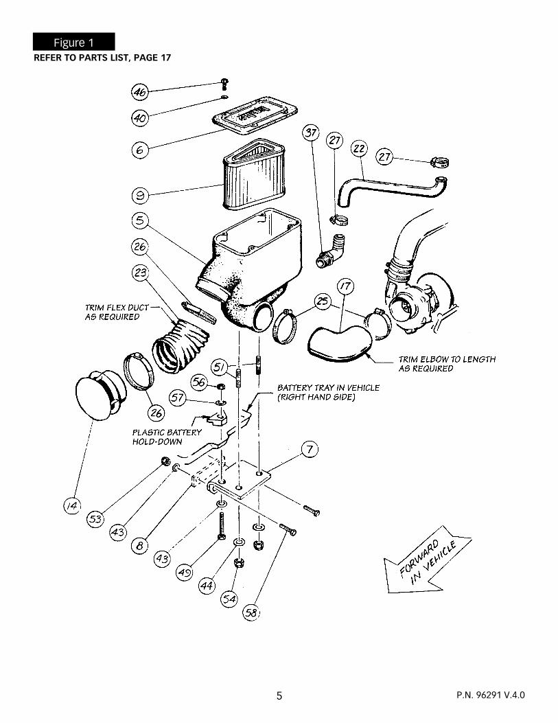
Figure 1REFER TO PARTS LIST, PAGE 17
P.N. 96291 V.4.0

INSTALLATION PROCEDURE
Disconnect ground cables from both batteries.
Remove the air filter, housing, intake silencer and flexible duct, and bracket from the exhaust
manifold. Cover the intake manifold opening with a clean rag to prevent foreign objects from entering the intake manifold.
Adjust the injector pump. Refer to the INJECTION PUMP ADJUSTMENT section. When the pump
adjustment is completed, make sure that the ground cables from both batteries are disconnected, then continue with the following steps.
1982–1987 MODELSRemove two crankcase vent tube assemblies
from the intake manifold vent nipples. Install two 3⁄4” I.D. caps on the nipples and retain with spring clamps. See Figure 2.
1988 AND NEWER MODELSA. Remove anti-depression valve (CDR) and hose from right hand valve cover and intake manifold. Save valve and hose for re-installation.B. Install 1” dia. rubber cap over fitting on intake manifold where hose was removed. Use a No. 16 hose clamp, provided, to secure the cap.
Remove and discard air inlet gasket from the intake manifold. Remove air filter mounting
studs. Install two new pressure chamber studs with two 5⁄16” thick spacers between studs and intake manifold.
NOTE: On light-duty engines which employ an E.G.R. valve, a light-duty E.G.R. Valve Application Kit, Banks P.N. 21056, will be required for E.G.R. valve hook-up. On these engines, do not install 5⁄16” spacers, but refer to instructions included in Application Kit.
Install new air inlet gasket provided on the intake manifold. Install pressure chamber over studs,
secure with two sealing washers, 5⁄16” I.D. x 3⁄4” O.D. flat washers and 5⁄16” – 24 locknuts. Slip a piece of blue 21⁄2” I.D. x 23⁄8” silicone hose on the air inlet nipple. Install a 1⁄8” NPT pipe plug in the left rear corner of the pressure chamber if optional boost gauge is not to be installed. See Figure 2.
Raise the vehicle and support it on jack stands. Disconnect and remove exhaust pipes, mufflers
and tailpipes. Remove and retain one exhaust pipe “doughnut” gasket. If neither doughnut gasket is in reusable condition, replacements may be ordered from GM, part #14037813. Saw off the flared (manifold) end of the right exhaust pipe. Remove and retain the 3-bolt flange for future use.
Disconnect fuel lines from the fuel lift pump (right front corner of engine block).
Remove fuel lift pump from engine.
Remove the adapter plate from engine block. Do not let fuel pump rod fall out.
If fuel pump rod wants to fall out, coat it with a heavy grease, such as chassis or wheel bearing
grease, to help keep it in place in the engine block.
Clean gasket surfaces on engine block and fuel pump mounting flange.
Install new adapter/drain plate to engine block using original bolts and new gaskets supplied.
Use silicone sealer on the gasket surfaces.
Re-install fuel pump to adapter plate with original bolts and new gaskets supplied. Use
silicone sealer on the gasket surfaces.
Re-attach fuel lines to the fuel pump.
Lower the vehicle.
Disconnect the glow plug wires and remove the glow plugs.
Remove the right (passenger side) exhaust manifold from engine. Retain all mounting bolts.
Clean the cylinder head mounting surface.
1.
2.
3.
4.
5.
6.
7.
8.
9.
10.
11.
12.
13.
14.
15.
16.
17.
18.
6
Figure 2
P.N. 96291 V.4.0
7
Drain coolant from radiator. Remove the lower radiator hose. Install the new radiator hose
provided. Relocate the ground wire on the frame rail to an alternate bolt hole location that will not allow the bolt head to rub against the radiator hose. Replace coolant.
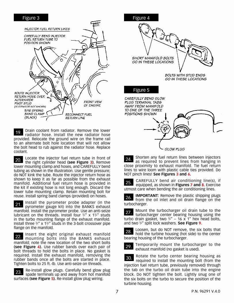
Locate the injector fuel return tube in front of the right cylinder head (see Figure 3). Remove
lower mounting clamp and hoses, and CAREFULLY bend tubing as shown in the illustration. Use gentle pressure; do NOT kink the tube. Route the injector return hose as shown to keep it as far as possible from the exhaust manifold. Additional fuel return hose is provided in the kit if existing hose is not long enough. Discard the lower tube mounting clamp. Retain mounting bolt for reuse. Install spring band clamps (provided) on hoses.
Install the pyrometer probe adapter (in the pyrometer gauge kit) into the BANKS exhaust
manifold. Install the pyrometer probe. Use an anti-seize lubricant on the threads. Install four 3⁄8” x 13⁄4” studs in the turbo mounting flange of the exhaust manifold. Install three 3⁄8” x 13⁄4” studs in the 3-bolt crossover pipe flange on the manifold.
Insert the eight original exhaust manifold mounting bolts into the BANKS exhaust
manifold; note the new location of the two short bolts (see Figure 4). Use rubber bands over each pair of bolt threads to hold the bolts in place. No gasket is required. Install the exhaust manifold, removing the rubber bands once all the bolts are started in place. Tighten bolts to 25 ft.-lb. Use anti-seize on threads.
Re-install glow plugs. Carefully bend glow plug spade terminals up and away from hot manifold
surfaces (see Figure 5). Re-install glow plug wiring.
Shorten any fuel return lines between injectors as required to prevent lines from hanging in
close proximity to exhaust manifold. Tie fuel return lines to wire loom with plastic cable ties provided. Do NOT pinch lines! See Figures 3 and 6.
CAREFULLY bend air conditioning line(s), if equipped, as shown in Figures 7 and 8. Exercise
utmost care when bending the air conditioning lines.
IMPORTANT: Remove the plastic shipping plugs from the oil inlet and oil drain flange on the
turbocharger.
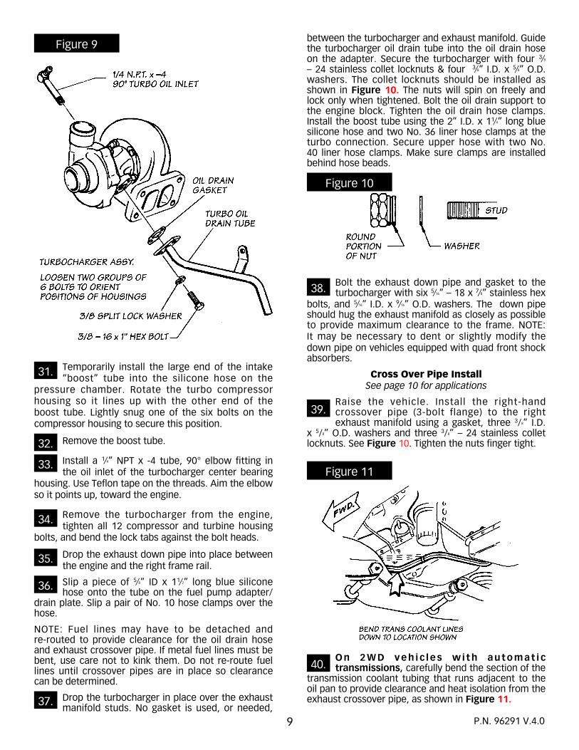
Mount the turbocharger oil drain tube to the turbocharger center bearing housing using the
turbo drain gasket, two 3⁄8” – 16 x 1” hex head bolts, and two 3⁄8” split lock washers. See Figure 9.
Loosen, but do NOT remove, the six bolts that hold the turbine housing (hot side) to the center
bearing housing of the turbocharger.
Temporarily mount the turbocharger to the exhaust manifold (no gasket is used).
Rotate the turbo center bearing housing as required to install the mounting bolt (from the
injection fuel return tube, previously removed) through the tab on the turbo oil drain tube into the engine block. Do NOT tighten the bolt. Lightly snug one of the six bolts on the turbo to secure the position of the turbine housing.
25.
26.
27.
28.
29.
20.
21.
22.
23.
24.
Figure 3 Figure 4
Figure 5
19.
P.N. 96291 V.4.0
30.

Figure 6
Figure 7
Figure 8
8 P.N. 96291 V.4.0
9
Temporarily install the large end of the intake “boost” tube into the silicone hose on the
pressure chamber. Rotate the turbo compressor housing so it lines up with the other end of the boost tube. Lightly snug one of the six bolts on the compressor housing to secure this position.
Remove the boost tube.
Install a 1⁄4” NPT x -4 tube, 90° elbow fitting in the oil inlet of the turbocharger center bearing
housing. Use Teflon tape on the threads. Aim the elbow so it points up, toward the engine.
Remove the turbocharger from the engine, tighten all 12 compressor and turbine housing
bolts, and bend the lock tabs against the bolt heads.
Drop the exhaust down pipe into place between the engine and the right frame rail.
Slip a piece of 5⁄8” ID x 11⁄2” long blue silicone hose onto the tube on the fuel pump adapter/
drain plate. Slip a pair of No. 10 hose clamps over the hose.
NOTE: Fuel lines may have to be detached and re-routed to provide clearance for the oil drain hose and exhaust crossover pipe. If metal fuel lines must be bent, use care not to kink them. Do not re-route fuel lines until crossover pipes are in place so clearance can be determined.
Drop the turbocharger in place over the exhaust manifold studs. No gasket is used, or needed,
between the turbocharger and exhaust manifold. Guide the turbocharger oil drain tube into the oil drain hose on the adapter. Secure the turbocharger with four 3⁄8
– 24 stainless collet locknuts & four 3⁄8” I.D. x 5⁄8” O.D. washers. The collet locknuts should be installed as shown in Figure 10. The nuts will spin on freely and lock only when tightened. Bolt the oil drain support to the engine block. Tighten the oil drain hose clamps. Install the boost tube using the 2” I.D. x 11⁄4” long blue silicone hose and two No. 36 liner hose clamps at the turbo connection. Secure upper hose with two No. 40 liner hose clamps. Make sure clamps are installed behind hose beads.
Bolt the exhaust down pipe and gasket to the turbocharger with six 5⁄16” – 18 x 7⁄8” stainless hex
bolts, and 5⁄16” I.D. x 9⁄16” O.D. washers. The down pipe should hug the exhaust manifold as closely as possible to provide maximum clearance to the frame. NOTE: It may be necessary to dent or slightly modify the down pipe on vehicles equipped with quad front shock absorbers.
Cross Over Pipe InstallSee page 10 for applications
Raise the vehicle. Install the right-hand crossover pipe (3-bolt flange) to the right exhaust manifold using a gasket, three 3/8” I.D.
x 5/8” O.D. washers and three 3/8” – 24 stainless collet locknuts. See Figure 10. Tighten the nuts finger tight.
On 2WD veh i c l es w i th au tomat i c transmissions, carefully bend the section of the
transmission coolant tubing that runs adjacent to the oil pan to provide clearance and heat isolation from the exhaust crossover pipe, as shown in Figure 11.
39.
40.
32.
33.
34.
35.
36.
37.
Figure 9
Figure 10
Figure 11
38.
P.N. 96291 V.4.0
31.

10
Figure 12REFER TO PARTS LIST, PAGE 17
P.N. 96291 V.4.0
* Required and sold separately: Cross-over Feed Pipes #12 and #13. Vehicle Specific Cross-Over Feed Pipe Kits:
Kit# 21051 1982-1991 Truck/Suburban 1500-2500 Light Duty 2-Door/2WD
Kit# 21053 1982-1991 Truck/Suburban/Blazer 1500-2500 Light Duty 2-Door/4WD
Kit# 21050 1982-1991 Truck/Suburban 2500-3500 Heavy Duty 2-Door/4-Door 2WD
Kit# 21052 1982-1991 Truck/Suburban 2500-3500 Heavy Duty 2-Door/4-Door 4WD
Slip the 3-hole floating exhaust pipe flange (previously removed) onto the left-hand
crossover pipe. Make sure the tapered side of the flange sits against the flare in the pipe. Insert the left-hand crossover pipe into the expanded end of the right-hand crossover pipe. NOTE: It may be necessary to back off the nuts or disconnect the right crossover pipe from the manifold to assemble the crossover pipes in place.
Install the assembled crossover pipes to the exhaust manifolds using the factory exhaust
“doughnut” seal, springs, and nuts on the left manifold. Tighten the stainless locknuts on the right manifold, and make sure the 3-bolt gasket is in place. Install a 2” exhaust U-clamp over the slip joint on the crossover pipe assembly. Install the crossover pipe heat shield (item 11) on the crossover pipe assembly as shown in Figure 12. Be sure the shield is positioned between the crossover pipe and the fuel and radiator hoses.
Check the clearances between the fuel lines and the exhaust crossover pipe in the vicinity of the
fuel pump. Shorten or reroute the rubber fuel hose(s) so there is a minimum of one inch clearance (11⁄2” or more is recommended) between them and the exhaust system. Additional 3⁄8” and 1⁄4” fuel hose is provided for the rerouting of the fuel supply and the injector return lines. Do not kink the fuel hoses.
Lower vehicle. Remove right-hand battery, jack and jack handle.
Remove engine coolant recovery bottle bolts, leaving those bolts that attach the bottle to the
battery tray. NOTE: Bolts may be accessible through the grille, wheel well or depressions in the bottle.
Remove battery tray and coolant bottle as an assembly.
On vehicles without cold inlet air duct, knock out the 4” diameter slug in the right-
side radiator bulkhead, remove the grille and install the plastic air inlet hood. Twist the hood into place. Reinstall the grille.
Temporarily mount the air filter bracket to the battery tray through the battery hold-down
threads using an M8-1.25 x 60mm metric full-thread bolt and 5⁄16” I.D. x 3⁄4” O.D. washer. See Figure 1. Make sure the narrow side of the bracket sits against the vertical support section of the battery tray.
Using the bracket as a template, drill two 11⁄32” diameter holes through the battery tray.
Bolt the bracket and the back-up plate (located opposite the bracket, see Figure 1) to the
battery tray with two 5⁄16” – 24 x 1” hex bolts, 5⁄16” I.D. x 3⁄4” O.D. washers and 5⁄16” – 24 locknuts. Remove the metric bolt and washer, apply Loctite to 1⁄2” of the threads nearest head of the bolt, reinstall and tighten (see Figure 1 for assembly sequence).
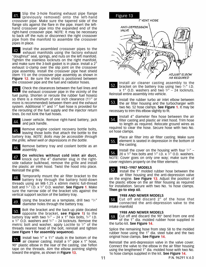
Install two 3⁄8” x 11⁄2” studs in the bottom of the air cleaner casting. Install a 3⁄4” pipe x 1” hose,
90° plastic elbow in the rear of the casting. Use Teflon tape on the threads. Aim the elbow pointing slightly toward the engine, as shown in Figure 13.
Install air cleaner casting assembly to the bracket on the battery tray using two 7⁄16” I.D. x 1” O.D. washers and two 3⁄8” – 24 locknuts.
Reinstall entire assembly into vehicle.
Install the rubber turbo air inlet elbow between the air filter housing and the turbocharger with two No. 52 hose clamps. See Figure 1. It may be
necessary to trim this elbow slightly to fit.
Install 4” diameter flex hose between the air filter casting and plastic air inlet hood. Trim hose to length as required. Relocate ground wires as
required to clear the hose. Secure hose with two No. 64 hose clamps.
Place air filter into air filter casting. Make sure element is seated in depression in the bottom of the casting.
Install the cover on the housing with four 7⁄16” – 20 x 3⁄4” hex bolts and 1⁄4” I.D. x 1⁄2” O.D. washers.
NOTE: Cover goes on only one way; make sure the cover registers properly on the filter element.
1982–1987 MODELSInstall the 1” molded rubber hose between the air filter housing and the anti-depression valve
on the engine. See Figure 13. Adjust the position of the plastic elbow on the air filter housing as required for installation. Secure with two No. 16 hose clamps. Then go to step 60.
1988 AND NEWER MODELSCut off and discard 2” of the hose that connected the anti-depression valve to the
intake manifold
1988 AND NEWER MODELSCut off and discard the 90° bend from one end of the 1” dia. molded rubber hose supplied in
the turbo kit. See Figure 14.
Splice the remaining hose from step 58 to the molded rubber hose using the 1” dia. steel tube and the two original hose clamps. See Figure 14.
Reinstall the anti-depression valve in the valve cover. Connect the valve to the elbow in the air filter housing using the lengthened 1” dia. molded hose with two No. 16 hose clamps supplied in the kit. See Figure 14.
Figure 13
42.
43.
44.
45.
46.
47.
48.
49.
50.
51.
52.
54.
53.
56.
57.
58.
59.
11
55.
P.N. 96291 V.4.0
41.

Remove the 1⁄4” NPT pipe plug from above the oil filter on the engine block (see Figure 15). The
plug is 1⁄4” female square drive. Use a pipe plug socket such as a Snap-On PP408, to remove the plug. Do NOT use 1⁄4” ratchet, extension adapters, etc. as they may break.
Install a 1⁄4” NPT x - 4AN adapter in place of the 1⁄4” NPT pipe plug removed. Use Teflon tape on
the pipe thread end. Install a -4 male x female, 90° swivel elbow on the adapter fitting. Aim the elbow up and tighten.
Connect one end of the stainless braided Teflon hose assembly to the swivel elbow.
Route the hose assembly up the back of the left cylinder head, then forward above the intake
manifold runners. Check that hose does not contact sharp edges on the firewall. NOTE: On some models, the oil cooler tubes will be directly above the swivel elbow. In this case, aim the swivel elbow down, and loop the hose assembly up and behind the rear oil cooler line.
Connect the other end of the braided Teflon hose assembly to the oil inlet fitting on the
turbocharger. Tie the hose to the cross-over casting at the front of the engine with plastic cable ties (see Figure 16). NOTE: If the hose is not long enough to reach the turbo when routed over the intake manifold, run the hose under the manifold and to the turbo.
Wrap one 14” x 6” aluminum heat blanket around any hoses that pass directly over the
turbine (exhaust) side of the turbocharger. Route (and wrap) the right-hand negative battery cable along with these hoses. Secure the heat blanket with three wire ties spaced along its length (see Figure 6).
Wrap a 14” x 6” aluminum heat blanket around the exhaust head pipe where it passes the glow
plugs and injectors at the rear of the cylinder head. (see Figure 6). Position the blanket so it extends 1” to the rear of the temperature switch on the cylinder head, and protects the glow plug wiring and injector fuel return hoses. Secure the blanket with three wire ties spaced along its length.
Reinstall the battery in the right-hand battery tray using the factory hold-down clamp and the
M8-1.25 metric hex nut and 3⁄8” ID x 7⁄8” OD washer. Adjust the position of the battery so the negative terminal will have as much clearance as possible to the air filter housing.
63.
64.
65.
66.
67.
Figure 14
Figure 15
Figure 16
12 P.N. 96291 V.4.0
60.
61.
62.

Reconnect the positive battery cable only, making sure there is ample clearance between
terminal and the air inlet connection.
Reroute the positive battery cable back to the starter solenoid, keeping it clear of the exhaust
system, moving parts, sharp edges, etc.
Remount the jack and jack handle. NOTE: On some models, the jack must be rotated 90
degrees to clear the air filter housing.
Install the pyrometer (exhaust temperature gauge) following the instructions in the
pyrometer kit. A gauge panel is included for under-dash mounting. Check that any electrical connections are not exposed where they could come in contact with ground and render the gauges inoperative. Keep all wiring away from exhaust heat and any mechanical components that could damage the wire.
If optional instruments were ordered, they may be installed at this time. Follow the instructions
provided with the individual instruments. Route all instrument wiring and tubing away from the exhaust heat and mechanical components that could cause damage. NOTE: Remove the 1⁄8” NPT pipe plug from the left rear corner of the pressure chamber for the boost gauge connection, if this gauge is to be installed.
Install muffler and exhaust system (not included with the turbo system) as shown in Figure 17.
Because of various vehicle/chassis combinations, the illustration provided is general, but typical of the exhaust system routing.
A separate 3” high-flow exhaust system is available from BANKS. This exhaust system includes a special low restriction 3” core muffler, pre-formed tubine sections and all components necessary to install the complete exhaust system. The BANKS 3” exhaust system is required for emissions legal applications.
NOTE: The turbocharger must be oil-primed before initial firing of the engine, as detailed in the following steps. This will prevent a “dry start” that might cause immediate bearing failure in the turbocharger.
Loosen the turbocharger oil feed hose at the turbocharger fitting.
Disconnect the wiring from the top of the fuel injection pump cover (note locations for
reconnection). This will prevent the engine from starting.
Reconnect both battery ground cables.
Crank engine until oil flows from oil feed connection at the turbo housing. Retighten
connection and crank engine until engine oil pressure gauge reading is in normal range. Cranking time should be limited to 20 to 30 seconds, followed by one minute of cooling. The cranking cycle should be repeated as required.
Reconnect wires to injection pump.
Turn ignition on and, after the glow plug light goes out, crank the engine, again in intervals of
20 to 30 seconds followed by one minute of cooling, until the engine starts. It may not start immediately, due to fuel lost when adjusting the injector pump. It also may be necessary to depress the accelerator pedal somewhat.
Visually check the installation for any improperly installed components, improperly routed wires
and hoses, intake air leaks and any wires or hoses too close to hot exhaust or turbo components, or sharp edges.
Run engine at idle for a few minutes, to allow it to warm. Check oil feed lines for leaks. Engine
may idle erratically or surge until air is fully purged from fuel system.
Drive vehicle. Several short bursts of acceleration are required to completely purge the fuel system of air. The engine may run slightly rough until the purge is complete, but will not in any way cause damage to the engine.
Check injector pump adjustment. See CHECKING ENGINE PERFORMANCE.
72.
73.
74.
75.
76.
77.
79.
80.
81.
78.
Figure 17
68.
69.
70.
71.
P.N. 96291 V.4.0
14
INJECTION PUMP ADJUSTMENT
To obtain the maximum available performance from your BANKS 6.2 Diesel Sidewinder Turbo System, and to comply with emissions requirements, it is necessary to make an adjustment to the fuel injection pump. The pump adjustment increases the fuel delivery capacity of the pump. This adjustment is made by turning an internal screw, found within the pump. Be sure to adjust the pump with the engine and pump cold. The pump adjustment will provide a 30% or greater increase in rear wheel horsepower. Suitable for general use, work trucks and towing.
NOTE: Exhaust gas temperature must not exceed 1100°F, as indicated on the EGT gauge (pyrometer) furnished with the kit. If the EGT approaches this temperature under heavy, uphill load, the fuel pump capacity adjustment must be reduced.
The pump adjustment can easily be set with the pump on the vehicle. If the condition of the pump is in question, or if the pump is to be removed from the vehicle, GALE BANKS ENGINEERING can provide the addresses and phone numbers of qualified Association of Diesel Specialists (ADS) pump service shops.
PUMP ADJUSTMENT PROCEDURE
NOTE: The engine must be COLD before starting this procedure.
NOTE: Utmost cleanliness should be exercised. Do NOT use any rags during the adjustment procedure. The lint from the rag can clog an injector. Lay all parts on clean newspaper during the adjustment procedure.
VERY IMPORTANT:SPECIAL INSTRUCTIONS FOR INJECTOR PUMP ADJUSTMENT ON LATE MODEL 6.2L ENGINES
Late model (’89 and newer) 6.2L diesel engines may have a plastic cap over the head of the guide stud. The position of the guide stud is pre-set at the factory, and should not be altered. On these models, adjust the pump as outlined in this section with the exception of step numbers 4, 5, 6, and 7. For these steps, follow the new step numbers: 4a, 5a, 6a, and 7a.
Make sure both battery ground cables are disconnected. Disconnect the wiring from the top
of the fuel injection pump cover. Note their location for reassembly.
Place a drip pan under the rear of the engine to catch fuel. Clean the upper portion of the pump and guide
stud (Allen-head bolt at the rear of the pump) with diesel fuel or a parts cleaning solvent. See Figures 18 and 19. Do NOT clean the pump while the engine is hot, as doing so may damage the pump.
Remove the fuel return line from the pump cover. Remove the top attaching bolt and loosen the lower
attaching bolt on the fast solenoid and place the solenoid
aside. Remove the pump cover bolts and remove the cover. IMPORTANT: Utmost care must be used to prevent damage.
Observe the position of the metering valve spring over the top of the guide stud. This position must be
duplicated exactly during the reassembly. See Figure 18.
Remove the Allen-head guide stud and sealing washer from the rear (outside) of the pump bowl. While
rocking the throttle lever toward the rear of the engine, lift out the governor spring assembly. Do not bend any springs or linkages.
Rotate the engine slowly by hand, IN A CLOCKWISE DIRECTION ONLY, using a breaker bar, a short
extension and a 15⁄16” socket on the vibration damper bolt to bring the Allen screw into view in the inspection slot in the bottom of the pump bowl (see Figure 19). On some late model trucks, ie: 1986 and later, it may be necessary to remove the front crankshaft pulley to gain access to the vibration damper bolt. DO NOT ATTEMPT TO ROTATE THE ENGINE WITH THE STARTER. Using a 5⁄32” Allen wrench, rotate the screw 1⁄4 turn, clockwise.
NOTE: The Allen-screw turns fairly tightly, and is self-locking. Turning the screw clockwise adds fuel. Keep track of your adjustments.
Reassemble the governor spring assembly and guide stud (see Figure 18). Replace the sealing washer, available from GM, if needed. Make sure the upper extension of the metering valve spring rides atop the guide stud. Torque down the guide stud snugly (85 inch-pounds).
Using a syringe or similar means, remove as much diesel fuel as possible from the injector pump housing.
This will make it easier to view the Allen-head adjustment screw through the slot in the bottom of the pump housing when it is rotated into position.
Rotate the engine slowly by hand, IN A CLOCKWISE DIRECTION ONLY, using a breaker bar, a short
extension and a 15/16” socket on the vibration damper bolt to bring the Allen screw into view in the inspection slot in the bottom of the pump bowl (see Figure 19). On some late model trucks it may be necessary to remove the front crankshaft pulley to gain access to the vibration damper bolt to turn the engine over. DO NOT ATTEMPT TO ROTATE THE ENGINE WITH THE STARTER. The Allen head screw may be hard to see — a flashlight or shop light may help. The screw will have to be adjusted at an angle from under the guide stud/spring assembly.
Using a 5⁄32” ball-end style Allen wrench, rotate the screw 1⁄4 turn, clockwise. NOTE: The Allen-screw turns
fairly tightly, and is self-locking. Turning the screw clockwise adds fuel. Keep track of your adjustments.
Go to step 8 and continue with pump reassembly.
1.
2.
3.
4.
5.
6.
4a.
5a.
6a.
7a.
P.N. 96291 V.4.0

Inspect the pump cover and make sure the seal is seated in the cover. Replace if questionable. Fill the
pump bowl with clean diesel fuel. Hold the throttle in the idle position. With the bolts removed from the pump cover, position the cover about 1⁄4” forward, toward the shaft end, and about 1⁄8” above the pump. Guide the cover downward and rearward into position, being careful not to damage the cover seal. Reinstall the bolts with the flat washers against the pump cover.
Reconnect battery cables. Turn the ignition switch to the “ON” position, and touch the pink solenoid
wire to the solenoid terminal. A clicking noise should be heard. If clicking is heard, proceed to next step. If not heard, the linkage may be jammed in the wide-open position. DO
NOT START THE ENGINE!! Remove the pump cover. Ground the solenoid lead (opposite hot terminal on the cover) and connect the pink wire to the cover terminal. With the ignition switch on, the solenoid in the cover should move the linkage. If not, free the linkage or replace the solenoid. Reinstall the cover.
Reinstall the fuel return line and fast idle solenoid.
Purge the air from the system as follows: Remove and fill all filters with clean diesel and reinstall the filters.
Detach all fuel supply hoses between the lift pump (fuel pump in the side of the engine) and the injection pump at their highest ends, and fill them with clean diesel fuel using a small funnel. Reattach the hoses.
9.
10.
11.
Figure 18
Figure 19
8.
P.N. 96291 V.4.0

Use your pyrometer (exhaust temperature gauge) to monitor your engine’s operation. At idle, EGT (exhaust gas temperature) will be very low, perhaps only 150°F. As the throttle is opened for higher speeds and greater loads, the EGT will rise. The highest EGT will be seen under maximum load at full throttle, such as climbing a steep grade with a heavily laden vehicle. Use caution if your EGT approaches 1050°F, with 1100°F being the ABSOLUTE MAXIMUM!
If the vehicle approaches those EGT levels under these conditions, downshift the vehicle to reduce the load, or back off the throttle. If frequent high EGT levels are encountered, the fuel delivery of the injection pump will have to be reduced by backing out the Allen head screw in the injection pump as indicated in the PUMP
ADJUSTMENT section. A high EGT can also be caused by a restrictive intake or exhaust system.
We recommend engine oil temperature be below 220°F, as measured in the oil pan. An optional oil temperature gauge is available from GALE BANKS ENGINEERING. Optimum oil temperature is 220°F. Continuously high oil temperature is indicative of the need for an additional oil cooler. If you do not have an oil temperature gauge, watch your oil pressure. Falling oil pressure under a heavy load is caused by rising oil temperature. Use caution.
We recommend that coolant temperature, also, should not exceed 220°F.
16
CHECKING ENGINE PERFORMANCE
Your BANKS turbocharged diesel engine should exhibit the following operating characteristics:
Cruise Conditions (constant 60mph on level road): EGT should be approximately 400°F; boost gauge, if so equipped, should read 1 to 11⁄2 pounds.
High Load Conditions (uphill with heavy load): EGT should typically be 900° to 1000°F, with 1100° as a maximum; boost levels may approach 9 pounds.
It is important to realize that diesels, unlike gasoline engines, run cooler with additional air. It is impossible to run a diesel too “lean.” Exhaust gas temperature rises as more fuel is added. Turbocharging a diesel typically lowers the EGT. Normal cruise condition EGT for a normally aspirated (non-turbocharged) diesel engine is typically 600° to 650°F. As noted above, cruise condition EGT for a turbocharged diesel is typically 400°F. This lower EGT translates directly to lower piston and valve temperatures, and significantly increased engine life.
It is also important to understand that turbocharged boost pressures are load related, that is the turbocharger makes boost only when called upon to do so (by load requirements). The turbo will not “make boost” with the transmission in neutral, but makes boost proportional to the load. Long uphill grades, with a heavy load, will result in maximum boost. In other words, the turbo makes boost only when it is needed. This characteristic makes turbochargers so attractive that the vast majority of long haul trucks and off-road earth moving equipment are equipped with turbochargers. Turbocharging typically results in more power and torque, better fuel economy and increased engine life.
OPERATING CHARACTERISTICS
P.N. 96291 V.4.0

PARTS LIST
1 BRACKET, Air Filter . . . . . . . . . . . . . . . . . . 7 41135 1 CHAMBER, Pressure . . . . . . . . . . . . . . . . . 3 41070 1 COVER, Air Filter Housing . . . . . . . . . . . . . 6 41050 1 FILTER ELEMENT, Banks Ram-Air . . . . . . . 9 41501 1 HOOD, Air Inlet Hose, 4” . . . . . . . . . . . . . . 14 41150 1 HOUSING, Air Filter . . . . . . . . . . . . . . . . . . 5 41030 1 MANIFOLD, Exhaust . . . . . . . . . . . . . . . . . 1 51002 1 OIL DRAIN, Turbo (2 pcs.) . . . . . . . . . . . . . 15 24066 1 PANEL, Gauge, 1 hole . . . . . . . . . . . . . . . . . 63001 1 PLATE, Bracket Back-up . . . . . . . . . . . . . . 8 41145 1 PROBE and ADAPTER, Pyrometer . . . . . . . 16 64001 1 ROLL, Teflon Tape . . . . . . . . . . . . . . . . . . . . 91099 8 TIE, Nylon Cable, 11” . . . . . . . . . . . . . . . . . 62002 1 TURBOCHARGER, Banks Sidewinder . . . . 2 24002 1 TUBE, Blue Loctite . . . . . . . . . . . . . . . . . . . 90001 1 TUBE, Boost . . . . . . . . . . . . . . . . . . . . . . . 4 41105 1 TUBE, Turbo Exhaust Down . . . . . . . . . . . 10 52010
CLAMPS: CLAMP, Exhaust, 3” . . . . . . . . . . . . . . . . . 1 52465 2 CLAMP, Hose, No. 8 . . . . . . . . . . . . . . . . . . 92808 2 CLAMP, Hose, No. 10 . . . . . . . . . . . . . . . . 28 92810 3 CLAMP, Hose, No. 16 . . . . . . . . . . . . . . . . 27 92816 2 CLAMP, Hose, No. 36 . . . . . . . . . . . . . . . . . 92836 2 CLAMP, Hose, No. 64 . . . . . . . . . . . . . . . . 26 92864 2 CLAMP, Liner, No. 36 . . . . . . . . . . . . . . . . 24 92837 2 CLAMP, Liner, No. 40 . . . . . . . . . . . . . . . . 20 92841 2 CLAMP, Liner, No. 52 . . . . . . . . . . . . . . . . 25 92853 2 CLAMP, Spring Band, 5⁄16”, Black . . . . . . . . . 292876 2 CLAMP, Spring Band, 7⁄16”, Red . . . . . . . . . . 92877 2 CLAMP, Spring Band, 7⁄8”, Black . . . . . . . . 29 92878
FASTENERS: 2 BOLT, 5⁄16”–24 x 1”, Hex . . . . . . . . . . . . . . . 58 91253 4 BOLT, 1⁄4”–20 x 3/4” HEX . . . . . . . . . . . . . . . 46 91117 2 BOLT, 3⁄8”–16 x 3/4” Hex . . . . . . . . . . . . . . . 48 91426 1 BOLT, M8–1.25 x 60mm Hex . . . . . . . . . . 49 91801 6 BOLT, Stainless, 5⁄16”–18 x 7⁄8”, Hex . . . . . . . 47 91227 2 NUT, Lock, Stainless Collet, 3⁄8”–24 . . . . . . 55 91418 1 NUT, M8–1.25 Hex . . . . . . . . . . . . . . . . . . 56 91802 4 NUT, Nylock, 5⁄16”–24, Hex . . . . . . . . . . . . . 53 91211 2 SPACER, P.C. Stud, 5⁄16” . . . . . . . . . . . . . . . 61 91019 2 STUD, Pressure Chamber (EGR) . . . . . . . . 50 91015 2 STUD, 3⁄8” x 11⁄2” (9/16” N.C. x 7/8” N.F.) . . . . . 51 91503 7 STUD, 3⁄8” x 13⁄4” (9/16” N.C. x 1” N.F.) . . . . . 52 91504 4 WASHER, AN, Stainless, 1⁄4” . . . . . . . . . . . 40 91101 8 WASHER, AN, Stainless, 5⁄16” . . . . . . . . . . . 41 91201 7 WASHER, AN, Stainless, 3⁄8” . . . . . . . . . . . 42 91401 5 WASHER, 5⁄16” SAE . . . . . . . . . . . . . . . . . . . 43 91202
2 WASHER, 3⁄8” USS . . . . . . . . . . . . . . . . . . . 44 91403 1 WASHER, 5⁄16” USS . . . . . . . . . . . . . . . . . . . 57 91203 2 WASHER, Split Lock, 3⁄8” . . . . . . . . . . . . . . 45 91404 2 WASHER, Thread Sealing O-Ring, 5⁄16” . . . . 60 91209
FITTINGS: 1 FITTING, Adapter, 1⁄4” NPT x -AN . . . . . . . . . 92101 1 FITTING, Elbow, 1⁄4” NPT x -4 AN Tall 90° . 36 92110 1 FITTING, Elbow, 3⁄4” NPT x 1” Hose 90° . . . 37 92030 1 FITTING, Elbow, Swivel, 1⁄4” Male x 1⁄4 AN . . 92162 1 FITTING, Pipe Plug, 1⁄8” NPT Hex Head, Brass 35 92250 1 FITTING, Plug Plug, 1” NPT Socket Head . . 92267 2 FITTING, Rubber Cap, 3⁄4” I.D. . . . . . . . . . . 59 92028 1 FITTING, Rubber Cap, 1” I.D. . . . . . . . . . . . 62 92029
GASKETS: 1 GASKET, Exhaust Crossover . . . . . . . . . . . 33 93155 1 GASKET, Fuel Lift Plate . . . . . . . . . . . . . . . 63 93505 1 GASKET, Fuel Lift Pump . . . . . . . . . . . . . . 62 93500 1 GASKET, Oil Drain . . . . . . . . . . . . . . . . . . . 32 93040 1 GASKET, Pressure Chamber . . . . . . . . . . . 34 93060 1 GASKET, Turbine Outlet . . . . . . . . . . . . . . 31 93001
HEATSHIELDS: 2 HEATSHIELD, Blanket, 14” x 6” . . . . . . . . . . 26001 1 HEATSHIELD, Crossover Pipe . . . . . . . . . . 11 26050 TIE, Wire, Heatshield Blanket . . . . . . . . . . . 26013
HOSES: 2 CAP, Plastic Vac . . . . . . . . . . . . . . . . . . . . . 92026 1 HOSE, Air Inlet, 4 x 8” . . . . . . . . . . . . . . . . 23 94090 1 HOSE, Assembly, Teflon, –4 AN x 58”. . . . . 94080 1 HOSE, Diesel Fuel, 1⁄4” I.D. x 24” . . . . . . . . . 94096 1 HOSE, Diesel Fuel, 3⁄8” I.D. x 18”. . . . . . . . . 94098 1 HOSE, Elbow, Turbo Inlet . . . . . . . . . . . . . 17 94005 1 HOSE, Injector Return, 1⁄8” I.D. x 12” . . . . . . 94092 1 HOSE, Lower Radiator . . . . . . . . . . . . . . . . 94020 1 HOSE, Molded Neoprene, 1” . . . . . . . . . . 22 94030 1 HOSE, Molded Silicone, 5⁄8 x 11⁄2” . . . . . . . . 21 94201 1 HOSE, Silicone, 21⁄2 x 23⁄8” . . . . . . . . . . . . . 18 94271 1 HOSE, Silicone, 2 x 21⁄4” . . . . . . . . . . . . . . . 19 94252 1 TUBE, Steel (hose splice), 1” O.D. x 13⁄4” . 28 94050
INSTRUCTIONS: 1 CARD, Product Registration . . . . . . . . . . . . 96360 1 DECAL, Fed. Emissions Comp Turbo . . . . . 96020 1 DECAL, GM 6.2 CARB E.O. . . . . . . . . . . . . . 96021 1 OWNERS MANUAL . . . . . . . . . . . . . . . . . . . 96291 2 PLAQUE, Banks Sidewinder . . . . . . . . . . . . 96003 1 WARRANTY STATEMENT . . . . . . . . . . . . . . . 96362
17
QTY. DESCRIPTION . . . . . . . . . . . . . . . . . . . . . . . . . . . . . . . . . . . . . . . . . . . . ITEM# PART# QTY. DESCRIPTION . . . . . . . . . . . . . . . . . . . . . . . . . . . . . . . . . . . . . . . . . . . . ITEM# PART#
P.N. 96291 V.4.0

CLEANING AND OILING THE BANKS RAM-AIR FILTER
NotificationThe Banks Ram-Air Filter comes pre-oiled and no oiling is necessary for initial installation. Use Banks RamAir Filter cleaning system (Part # 90094) available from Gale Banks Engineering to service the Air Filter.
PRE-CLEANINGT a p t h e e l e m e n t t o d i s l o d g e a n y l a r g e
embedded dirt, then gently brush with a soft bristle brush. NOTE: If complete cleaning is not practical at this time, reoil the element and reinstall in your vehicle.
S P R A Y - O N CLEANING
Spray Banks air-filter cleaner liberally onto the entire element and let soak for 10 minutes.
PAN CLEANINGLarge air-filter elements
can be rolled or soaked in a shallow pan of Banks air-filter cleaner. Remove immediately and let soak for approximately 10 minutes.
CLEANING HINTSUse only Banks air-filter cleaner. NO gasoline
cleaning, NO steam cleaning, NO caustic cleaning solutions, NO strong detergents, NO high-pressure car wash, NO parts cleaning solvents. Any of these NOs can cause harm to the cotton filter media plus SHRINK and HARDEN the rubber end caps.
RINSE OFFRinse off the element with
low-pressure water. Tap water is okay. Always flush from the clean side to dirty side. This removes the dirt and doesnot drive it into the filter.
DRYING HINTSAlways dry naturally. After rinsing, shake off all excess water and let the element dry naturally. DO NOT USE COMPRESSED AIR – DO NOT USE OPEN FLAME – DO NOT USE HEAT DRYERS!EXCESS HEAT WILL SHRINK THE COTTON FILTER MEDIA.
COMPRESSED AIR WILL BLOW HOLES IN THE ELEMENT.
AEROSOL OILINGAfter cleaning air filter always reoil
before using. Spray Banks Ram-Air filter oil down into each pleat with one pass per pleat. Wait 10 minutes and re-oil any white spots still showing.
OILING HINTSNever use a Banks Ram-Air filter without oil (the filter will not stop the dirt without the oil).
Use only Banks Ram-Air filter oil. Banks air-filter oil is a compound of mineral and animal oil blended with special polymers to form a very efficient tack barrier. Red dye is added to show just where you have applied the oil. Eventually the red color will fade but the oil will remain and filter the air. NEVER USE Automatic Transmission Fluid. NEVER USE Motor Oil. NEVER USE Diesel Fuel. NEVER USE WD40, LPS, or other light-weight oils.
REINSTALLReinstall your Banks Ram-Air filter element with proper care. Make sure the element seats
properly in the filter case. Install the cover making sure it’s in the right position. Tighten all the nuts, bolts, screws or clips to factory specifications.
DO NOT DISCARDAffix the “Do Not Discard” sticker to the filter case (included with every Banks replacement
element). Make sure you put the sticker in a highly visible place to alert your mechanic not to discard.
PERFORMANCE HINTSService every 50-100,000 miles on street-driven applications. Service more often in offroad or
heavy-dust conditions. If an air-filter restriction gauge is installed, then change the element when the air-filter restriction reaches 18”/H2O.
CAUTION! Extremely fine dust from agriculture or offroad use will pull the oil from the element. Frequent reoiling of the element’s clean side might be required. Completely service when practicable. For extra protection use an air-filter sealing grease on rubber ends of the element. Service only with Banks air-filter cleaner and Banks air-filter oil.
6.
7.
8.
9.
10.
1.
2.
3.
4.
5.
18 P.N. 96291 V.4.0

TROUBLE SHOOTING CHART
19
SYMPTOM
HIGH EGT.
EXCESSIVE FUEL SMOKE, (BLACK) POOR PERFORMANCE.
EXCESSIVE OIL SMOKE (BLUE).
LACK OF BOOST, EXCESSIVE OIL SMOKE, & POOR PERFORMANCE.
OIL WETTING OF THE INSIDE SURFACES OF THE BOTTOM OF THE AIR FILTER CASTING, AIR INLET ELBOW, AND TURBO COMPRESSOR HOUSING.
LOW BOOST, POOR PERFORMANCE, SOMETIMES WITH HIGH EGT.LACK OF BOOST OR LOW BOOST, POOR PERFORMANCE.
PYROMETER NOT WORKING.
GRADUAL LOSS OF PERFORMANCE, AND POSSIBLY BOOST (“FLATTENS OUT” AT HIGH RPM).
CAUSE
EXCESSIVE FUEL DELIVERY.FAULTY INJECTOR(S).RESTRICTED EXHAUST SYSTEM.FAULTY INJECTOR(S).
DIRTY AIR CLEANER.RESTRICTED AIR INTAKE.
POOR QUALITY OR DIRTY DIESEL FUEL.
BLOCKED OR RESTRICTED TURBO OIL DRAIN.EXCESSIVE ENGINE BLOWBY BEING VENTED INTO THE AIR INTAKE.DAMAGED TURBO BEARINGS, CAUSED BY DIRTY OIL OR LACK OF LUBRICATION.
WORN OR DAMAGED ENGINE COMPONENTS.THIS IS NORMAL. THE OIL IS PRESENT IN THE VAPORS FROM THE CRANKCASE VENTILATION SYSTEM. THESE VAPORS ARE ALSO PRESENT IN THE INTAKE MANIFOLD PRIOR TO TURBOCHARGING. THIS IS NOT THE RESULT OF A FAILED TURBO SHAFT SEAL.RESTRICTED EXHAUST SYSTEM.
INTAKE SYSTEM LEAKS.
EXHAUST SYSTEM LEAKS AHEAD OF TURBOCHARGER EXHAUST INLET.BROKEN TURBOCHARGER BLADES CAUSED BY FOREIGN OBJECTS ENTERING THE INTAKE OR EXHAUST SYSTEM. CHECK FOR REVERSED WIRES.POOR WIRE CONNECTIONS.WIRING CONNECTIONS SHORTED TOGETHER.CLOGGED, OR PARTIALLY CLOGGED, FUEL FILTER.
REMEDY
CHANGE INJECTOR PUMP SETTING.REPAIR INJECTOR(S).CHECK FOR OBSTRUCTIONS.REPAIR INJECTOR(S).
CLEAN OR REPLACE.CHECK FOR BLOCKED OR COLLAPSED AIR INTAKE HOSES.REPLACE FILTERS, CLEAN LINES, INJECTORS AND TANK AS REQUIRED.ELIMINATE RESTRICTIONS OR LOW SPOTS IN THE DRAIN LINE.REPLACE WORN PISTON RINGS OR VALVE GUIDES. CHECK THE ENGINE OIL LEVEL.REBUILD TURBO, CHECK OIL LEVEL, CHANGE OIL AND FILTER AT REGULAR SERVICE INTERVALS.CHECK COMPRESSION, REPLACE RINGS OR VALVES.IF NO BLUE SMOKE IS PRESENT AT THE VEHICLE’S TAILPIPE, NO ACTION IS NECESSARY. IF BLUE SMOKE IS PRESENT, THE CAUSE MAY, OR MAY NOT, BE FROM THE TURBO. POOR ENGINE OIL CONTROL (WORN RINGS OR VALVE GUIDES, OR TOO MUCH OIL) MAY CAUSE THIS CONDITION.ELIMINATE RESTRICTIONS, CHECK FOR OBSTRUCTIONS.
LOCATE AND SEAL LEAKS; CHECK SEAL BETWEEN PRESSURE CHAMBER AND INTAKE MANIFOLD.LISTEN FOR LEAKS, REPAIR AS NECESSARY.
REBUILD TURBOCHARGER; ELIMINATE MEANS OF FOREIGN OBJECT ENTRY.
REVERSE WIRES.CLEAN AND SECURE CONNECTIONS.INSULATE CONNECTIONS.
REPLACE FUEL FILTER(S).
P.N. 96291 V.4.0

Gale Banks Engineering546 Duggan Avenue • Azusa, CA 91702(626) 969-9600 • Fax (626) 334-1743
Product Information & Sales: (888) 635-4565Customer Support: (888) 839-5600Installation Support: (888) 839-2700bankspower.com