Embed Size (px)
Citation preview

2
owner’s manual

3

Gentile Cliente, desideriamo ringraziarLa per aver deciso di vivere la Sua passione per la musica in compagnia di Aida. Poiché è nostro preciso interesse che Lei ottenga la miglior soddisfazione possibile nell’ascolto, La invitiamo a leggere attentamente, prima dell’installazione, questo manuale d’istruzioni per l’uso e la manutenzione. Per un risultato ancor più sicuro ed ottimale, Le consigliamo di contattarci direttamente. Sapremo indicarLe il più idoneo interfacciamento con le elettroniche ed il più corretto posizionamento nel Suo ambiente d’ascolto.
Dear Customer,We would like to thank you for choosing Aida to live your passion for music. As it is of paramount importance to us that your listening experience provides the greatest possible satisfaction, we ask you to read the following instruction and maintenance manual in detail, prior to carrying out installation. To ensure the best possible results we suggest you contact us directly for guidance in choosing the best electronic interface and set up in your listening environment.

5
• Leggere il presente manuale di istruzioni e conservarlo in luogo a portata di mano per ogni eventuale esigenza.
• Regolare i piedini di appoggio al fine di ottenere la migliore condizione di stabilità.
• Nel caso di collocazione del diffusore acustico su superfici di appoggio flottanti (es. soppalchi, rialzi in legno ecc...) verificare in via preliminare che la portata relativa sia sufficiente a sostenere il peso del o dei diffusori acustici. Verificare inoltre che sussista un attrito sufficiente ad evitare spostamenti del diffusore acustico con le vibrazioni da esso prodotte in condizioni operative.
• Evitare di appoggiare al diffusore acustico oggetti estranei che possano comprometterne la stabilità. Non collocare contenitori di acqua e sostanze liquide al di sopra del mobile del diffusore.
• Attenersi ad uno degli schemi di collegamento indicati nel presente manuale. Il collegamento in parallelo di due o più diffusori può danneggiare il Vostro amplificatore. In caso di dubbio rivolgersi al vostro rivenditore di fiducia.
• Nel corso del funzionamento dell’impianto audio evitare un ascolto ad alto volume ed in prossimità degli altoparlanti. Ciò può provocare danni anche permanenti all’apparato uditivo. Mantenete i bambini ad una distanza di sicurezza di almeno 50 cm dai diffusori acustici.
• Gli altoparlanti producono attorno ad essi un campo elettromagnetico innocuo per l’essere umano e per gli animali ma che può disturbare il funzionamento di apparecchiature elettroniche come monitor
• Read all instructions contained in this manual and keep it for future reference.
• Adjust the supporting feet in order to obtain the best possible stability.
• When the speaker is located on a non rigid surface (floating floors, plinths, wooden rises etc.) first check that the supporting weight is sufficient for that of the speaker. Also verify that there is sufficient friction in order to avoid movement of the speaker through vibrations whilst in use.
• Do not put objects on top of the speaker which may compromise its stability. Do not place objects containing water or liquids on the speaker cabinet.
• Follow the connection guide given in this manual. The parallel connection of two or more speakers may damage your amplifier. When in doubt contact your local dealer.
• While the system is operating avoid listening at high volumes and close to the speakers. It can cause permanent damage to your hearing. Keep children at a safe distance from the speakers, at least 50 cm.
• The speakers produce an electromagnetic field which is harmless to humans and pets but can cause disturbances in the correct functioning of electronic equipment such as monitors or cathode tube TVs when
raccomandazioni di sicurezza e indicazioni per il corretto impiego del prodotto
safety recommendations and precautions for correct product use

6
e televisori con schermo a tubo catodico qualora queste vengano collocate nelle immediate vicinanze del diffusore acustico. Nel caso in cui ciò si verifichi, allontanare semplicemente e lentamente i due apparati uno dall’altro. Per motivi di cautela si sconsiglia di appoggiare sul diffusore acustico carte di credito o simili a lettura magnetica.
• La tecnologia di funzionamento degli altoparlanti verte su principi dell’elettromagnetismo e pertanto l’utilizzatore dovrà evitare di utilizzare apparati che generino forti campi elettromagnetici, i quali potrebbero disturbare il funzionamento dei diffusori acustici. Evitare di appoggiare sul mobile di questi ultimi apparati di ricetrasmissione come telefoni cellulari, cordless, sistemi intercom, ecc.
• Mantenere a distanza cavi di collegamento amplificatore-diffusore acustico e cavi di alimentazione di rete. Questi ultimi convogliano una tensione alternata alla frequenza di 50Hz/60Hz ed intensità che può essere elevata e come tali producono attorno ad essi un campo elettromagnetico alla medesima frequenza. In caso di accoppiamento tra cavi di segnale e cavi di alimentazione, la conseguenza sarà la comparsa di un fastidioso ronzio. Nel caso in cui ciò si verifichi provvedere ad allontanare tra di loro cavi di segnale e cavi di alimentazione.
• Prestare grande attenzione al montaggio /smontaggio del pettine tendifilo. Assicurarsi che i perni della staffa inferiore siano ben inseriti nelle rispettive sedi prima di tendere i fili per fissare la staffa superiore.
• I morsetti serrafilo sono provvisti di innesto per connettore a banana (banana plug) ostruito da tappo rimovibile al fine di evitare accidentali collegamenti a prese di rete non protette. Rimuovere i tappi in plastica rossa e nera unicamente nel caso si intenda avvalersi di detto tipo di terminazione e cautelarsi che l’altro capo del cavo venga collegato ai morsetti di uscita di potenza dell’amplificatore.
placed in close proximity. If this occurs, simply and slowly distance one from the other. As a precaution it is not advisable to place credit cards or similar magnetically read objects on top of the speaker.
• The technology behind the functioning of the speakers is based on the principles of electromagnetism and thus the user should avoid operating equipment that generates strong electromagnetic fields as these could effect the correct functioning of the speaker. Avoid placing transmitting devices such as mobile phones, cordless phones, intercom systems etc. on top of the speakers.
• Keep amplifier-speaker connection leads and power cables separate. Power cables use an alternating voltage at a frequency of 50Hz/60Hz and an intensity that can be high and thus produce an electromagnetic field around them of the same frequency. In the case of coupling of these two types of leads an annoying hum will be apparent. If this should occur, maintain an adequate distance between the signal leads and the power cables.
• Be very careful during the assembly and disassembly of the strings grill metal plate. Check that the pins in the lower bracket are properly inserted before tightening the strings and securing the top bracket.
• The binding posts are fitted with a socket for banana plugs blocked by a removable cap which is aimed at avoiding accidental connection to unprotected electrical outlets. Remove the red and black plastic caps only if you intend to implement this type of connection and ensure that the other end of the cable is connected to the power output terminals of your amplifier.

7
FREQUENCY RESPONSE:20 Hz – 35.000 Hz, Stealth reflex included.
SENSITIVITY:92 db SPL (2.83V/1 m).
NOMINAL IMPEDANCE:4 ohm.
POWER HANDLING:100W – 1KW, without clipping.
DIMENSIONS:1725mm x 482mm x 780mm (HxWxD).
WEIGHT:330 Kg per pair – net weight / 550 Kg per pair - shipping weight (The shipping weight may slightly change from time to time because different humidity values over the year might affect the wooden boxes’weight).

8
design specifications
The combination of the two different materials, Avional and Gunmetal, allows eliminating any mutual resonance. The same way as the tweeter, the midrange is decoupled from the main baffle board and designed synergistically with its optimized “acoustic chamber”. A special coaxial anti-compressor is used, designed to remove cavity resonances and distortions.
WOOFERS:Sonus faber W22 XTR-12. A pair of Sonus faber designed 220 mm lightweight “sandwich” cone structure (high-tech syntactic foam core and two external surface skins of coated cellulose pulp) woofers are embebed in an acoustically amorphous “stealth reflex” chamber. Designed to blend perfectly with the special midrange and, at the same time, to have absolute definition in their range: the sandwich structure with outer paper pulp skins has the same sonic character of the midrange cone. A long-throw motor system with a 2” controlled “eddy current” voice coil is implemented for high speed, performance and linearity.Special coaxial anti-compressor are used, designed to remove cavity resonance and distortions.
INFRA WOOFER:Sonus faber SW32 XT-08. Sonus faber designed a 320 mm infra woofer, lightweight honeycomb composite sandwich cone structure with Nanocarbon technology for a maximum rigidity and implemented it in an acoustically amorphous “stealth reflex” chamber. The unit features a very powerful long throw motor with a 3” voice coil for ultra dynamic linearity. To perfectly match the low-end performance to different listening rooms it is possible to adapt the SPL of the infra woofer.
SOUND FIELD SHAPER:The special patented Sound field Shaper technology, a direct derivation from the “The”, allows the control of the direct/reverberant radiation ratio of the Aida. The sound field shaping module can be SPL optimized.
SOUND FIELD SHAPER TWEETER:29 mm ultra dynamic linearity neodymium dome driver. Optimized off-axis radiation for this special application.
SOUND FIELD SHAPER MIDRANGE:120 mm, paper pulp/natural fiber blend cone driver for maximum coherence with the front midrange emission.
CROSS-OVER:Non-resonant design, optimized amplitude/phase response for optimal space/time performance. “Paracross topology” on the tweeter hi-pass. The impedance at low frequencies is controlled for a clear and friendly amplifier performance. Triple staggered transfer function low frequency/room interface optimized filter. Highest quality is used in terms of the components: Mundorf “Supreme” Silver/Gold/Oil capacitors, Jantzen inductors. Cross-over: 55Hz - 180 Hz - 250 Hz - 3000Hz.
SYSTEM: 3.5 way, Sound field Shaper Technology, “Zero Vibration Transmission” technology, para-aperiodic vented box “Stealth Reflex System”, staggered low frequency floorstanding loudspeaker system.
CAbINET: “Lyra shape” design, dual side curvature, special cross grained okoumè plywood, used in a double thickness constriction layer damped configuration. Sub–structural ribs are strategically placed for total rejection of spurious vibrations and standing waves control. Two “dampshelves” (from “The” experience), i.e. CNC anodized machined avional “vibration dampers” (on the top and on the bottom of the cabinet) “stiffen” the column structure reducing consistently structural micro-vibrations coming from the cabinet walls and the transducers. The “Anima legata” system is used in an innovative way, encompassing the 3 inner chambers of the front firing drive units. A special steel rod, a high speed mechanical interface, concentrates the remaining micro-vibrations conveying them to the dual multiple “Tuned Mass Dampers”, i.e. two differently tuned special custom devices optimized to erase micro-vibrations, by oscillating in anti-phase. A totally new floating bridge “bow spring” suspension for vibrational interface has been devised to decouple the enclosure from the floor through the Zero Vibration Transmission technology, a patent pending suspension system, eliminating any acoustic feedback and any vibration propagation to the listening room.
TWEETER:Sonus faber “Arrow Point” DAD (Damped Apex Dome, synthesis of the classic dome and ring transducer) 29 XTR-06. A Sonus faber designed 29 mm moving coil driver, with Sonus faber’s vibration optimized mechanical interface. The ultra dynamic linearity is given by the new Neodymium motor system. Implemented with a natural wood acoustic labyrinth rear chamber, a mechanical anti-resonator designed for this application. To perfectly match the high frequency performance to different listening rooms and different tastes it is possible to adjust the SPL of the tweeter.
MIDRANGE:Sonus faber M18 XTR-08. A Sonus faber designed 180 mm neodymium magnet system ultra dynamic linearity midrange. CCAW wire is used on a composite former “eddy current free” voice coil. The dynamically linear magnetic field motor incorporates triple Kellog/Goeller rings. A special custom diaphragm is made with a real time air dried non pressed blend of traditional cellulose pulp, kapok, kenaf and other natural fibers, developed according to the most natural sound. To further inhibit any residual cone coloration we are using a transparent viscous surface damping coating.The basket is thoroughly optimized to eliminate any resonance, thanks to a high-tech dual metal (Avional and Gun Metal), CNC machined from solid billets.

9
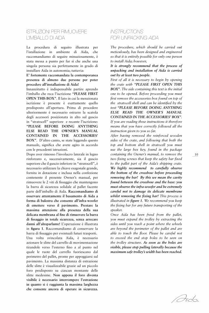
FIGURA 1 / FIGURE 1 fig 1

10
istruzioni per rimuovere l’imballo di aida
InstructIons for unpackIng aIDa
La procedura di seguito illustrata per l’istallazione in ambiente di Aida, che raccomandiamo di seguire minuziosamente, è stata messa a punto per far sì che anche una singola persona sia perfettamente in grado di installare Aida in autonomia; tuttavia:E’ fortemente raccomandata la contemporanea presenza di almeno due persone per poter procedere all’installazione di Aida!Innanzitutto è indispensabile partire aprendo l’imballo che reca l’iscrizione “PLEASE FIRST OPEN THIS BOX”. Il lato in cui la menzionata iscrizione è presente è esattamente quello predisposto all’apertura. Prima di procedere ulteriormente è necessario estrarre la scatola degli accessori posizionata in alto sul guscio in “stratocell” superiore e recante l’iscrizione: “PLEASE BEFORE DOING ANYTHING ELSE READ THE OWNER’S MANUAL CONTAINED IN THE ACCESSORIES’ BOX”. D’altro canto, se state leggendo questo manuale, significa che avete agito in accordo con le precedenti istruzioni.Dopo aver rimosso l’involucro laterale in legno rinforzato e, successivamente, sia il guscio superiore che il guscio inferiore in “stratocell”, è necessario utilizzare la chiave esagonale grande, fornita in dotazione e inclusa nella confezione contenente il presente Owner’s manual, per rimuovere le 2 viti di fissaggio che mantengono la barra di sicurezza solidale al pallet facente parte dell’imballo di Aida. Raccomandiamo di osservare attentamente il basamento di Aida a forma di balestra che consente all’infra-woofer di emettere verso il pavimento. Prestare la massima attenzione alla presenza della sua delicata membrana al fine di rimuovere la barra di fissaggio in totale sicurezza, senza arrecare danni all’altoparlante! L’operazione è illustrata in figura 1. Raccomandiamo di conservare la barra di fissaggio per eventuali futuri trasporti.Una volta svincolata Aida, è necessario azionare le slitte del carrello di movimentazione tirandole verso l’esterno fino a al punto nel quale le ruote del carrello fuoriescano dal perimetro del pallet, pronte per appoggiarsi sul pavimento. La massima distanza di estrazione delle slitte è visualizzabile grazie ad un piccolo foro predisposto su ciascun montante delle slitte medesime. Non appena il foro diventa visibile è necessario interrompere l’estrazione in quanto si è raggiunta la massima larghezza che consente ancora di operare in sicurezza.
The procedure, which should be carried out meticulously, has been designed and engineered so that it is entirely possible for only one person to install Aida; however, It is strongly recommend that the process of unpacking and installation of Aida is carried out by at least two people. First of all it is necessary to begin by opening the crate with “PLEASE FIRST OPEN THIS BOX”. The side containing this text is the initial one to be opened. Before proceeding you must first remove the accessories box found on top of the stratocell shell and can be identified by the text “PLEASE BEFORE DOING ANYTHING ELSE READ THE OWNER’S MANUAL CONTAINED IN THE ACCESSORIES’ BOX”. If you are reading these instructions it therefore means that you have correctly followed all the instruction given to you so far.After having removed the reinforced wooden sides of the crate, and following that both the top and bottom shell in stratocell you must use the large hex key, found in the package containing the Owner’s manual, to remove the two fixing screws that keep the safety bar fixed to the pallet part of the Aida’s shipping crate. We highly recommend to carefully observe the bottom of the crossbow before proceeding removing the bar! By this we mean the cavity found between the crossbow and the base: you must observe the infra-woofer and be extremely careful not to damage its delicate membrane whilst removing the fixing bar! This process is illustrated in figure 1. We recommend you keep the fixing bar for any future transporting of the speaker.Once Aida has been freed from the pallet, you must expand the trolley by extracting the sides until you reach a point where the wheels are beyond the perimeter of the pallet and are able to touch the floor. Please be careful not to exceed the end stop holes to be seen on the trolley structure. As soon as the holes are visible, please stop pulling laterally because the maximum safe trolley’s width has been reached.
11
FIGURA 4 / FIGURE 4
FIGURA 3 / FIGURE 3
FIGURA 2 / FIGURE 2
fig 3
A
fig 4

12
The achieved width is more the enough for easily going on in removing the pallet. Now you can turn the four handles anticlockwise at the same time so that the wheels of the trolley reach the floor, as seen in figure 2. Once the wheels touch the ground you are required to begin lifting Aida to the minimum height needed to be able to remove the pallet from under the speaker, as shown in figure 3. Before beginning this phase we recommend you open the package that contained the Owner’s Manual and find:
• another hex key, smaller than the one used previously;
• the rear feet of Aida with threaded pins;• the locking rings and pins for the front feet;• the magnetic covers for the front feet;
The aim is to prepare everything so that you are ready for the installation as soon as you have removed the pallet.You are strongly advised not to carry out this operation alone but to use the cooperation of at least one other person and to proceed both cautiously and slowly in turning the handles anticlockwise. You must raise Aida only to the minimum height required to slide the pallet out from under the speaker, PROCEED WITH CAUTION, slow and continuous movement is required in order to not tilt or shift the weight of the speaker to one side!!!Please note that the package contains the 2 rear feet, the 2 locking rings for the front feet and the magnetic front covers.Once the pallet has been removed the rear feet with threaded pins must be completely screwed into place on the base of the speaker. The front feet locking rings must also be inserted, making sure the raised side faces up, then finally the magnetic covers should be fixed to the rounded ends of the front pins. This process is shown in figure 4.
Detta larghezza sarà comunque bastevole a procedere agevolmente nelle operazioni di rimozione dell’imballo. A questo punto, ruotando contemporaneamente in senso antiorario le 4 manovelle degli argani del carrello, sarà possibile far adagiare le ruote del carrello di movimentazione a terra, come illustrato in figura 2. Non appena le ruote poggiano a terra, si rende necessario procedere al sollevamento di Aida fino a raggiungere un’ altezza sufficiente a sfilare il pallet dalla base del diffusore, come illustrato nella figura 3. Prima di procedere a quest’operazione si raccomanda di aprire la confezione che conteneva l’ Owner’s manual che state sfogliando. All’interno troverete:
• un’altra chiave esagonale, più piccola di quella sin qui utilizzata;
• i piedini posteriori di Aida già muniti di perno filettato;
• le ghiere di bloccaggio dei perni dei piedini anteriori;
• le sottopunte magnetiche sempre relative ai piedini anteriori.
Lo scopo è predisporre il tutto a portata di mano per essere pronti all’installazione di Aida non appena il pallet sarà stato sfilato. Per l’operazione di sollevamento si raccomanda di avvalersi della cooperazione di almeno una seconda persona, procedendo molto adagio nella rotazione antioraria delle quattro manovelle. Sollevare Aida, lo ribadiamo, solo per l’altezza necessaria a sfilare il pallet, PRESTANDO LA MASSIMA ATTENZIONE e procedendo in modo in graduale e continuo, al fine di evitare di inclinare il diffusore, sbilanciando il suo peso su uno dei suoi lati!!!Si prega di prestare nuovamente attenzione al fatto che all’interno della confezione sono contenuti i 2 piedini posteriori, le 2 ghiere di bloccaggio dei perni dei piedini anteriori e i sottopunta magnetici anteriori. Una volta sfilato il pallet dovranno essere avvitati a fondo i piedini posteriori provvisti di perno filettato nelle sedi relative poste al di sotto della base di Aida e dovranno essere inserite le ghiere di bloccaggio dei perni anteriori facendo attenzione a rivolgerne la parte in rilievo verso l’alto. Dovranno essere infine fatti aderire i sottopunta magnetici all’estremità arrotondata dei perni dei piedini anteriori. Il tutto è illustrato in figura 4.

13
fig 5
fig 6 FIGURA 6 / FIGURE 6
FIGURA 5 / FIGURE 5

14
Once the feet have been fixed you are required to lower Aida, carefully placing it on the floor, by turning the handles clockwise.We strongly recommend you do not carry out this process alone but use the cooperation of at least one other person and that you proceed with great care in the clockwise turning of the handles. ATTENTION MUST BE GIVEN when placing Aida, proceed slowly and continuously, without shifting its weight or unbalancing the speaker!!!Once Aida has been placed on the ground, resting only on its feet and with the wheels of the trolley completely off the floor, you are required to slide the arms of the trolley as far as they will go towards the speaker in order to make the structure completely stable and safe to transport, as shown in figure 5. At this point you must raise Aida again, only a few centimetres, by turning the handles anticlockwise and again taking great care in not shifting the weight of the speaker to either side but rather lifting it in a homogeneous manner. Aida is now ready for transporting to the listening environment, placing it approximately in its designated position by simply turning the handles clockwise. The next step is to remove the trolley from the first Aida in order to use it in transporting the second Aida. You must proceed, once the first Aida is firmly resting on the ground, in its temporary location in the listening room and with the wheels of the trolley completely off the floor, by pulling the arms of the trolley towards you until the are completely free from the supporting bars, as seen in figure 6.
Non appena completato il montaggio dei piedini, sarà necessario abbassare Aida fino a farla adagiare al pavimento, ruotando le manovelle in senso orario.Anche per questa operazione si raccomanda di avvalersi della cooperazione di almeno una seconda persona e procedendo molto adagio nella rotazione oraria delle quattro manovelle. Adagiando Aida SI DEVE PRESTARE LA MASSIMA ATTENZIONE e procedere lentamente, in modo graduale e continuo, al fine di evitare di inclinare il diffusore, sbilanciando il suo peso su uno dei suoi lati!!!Quando Aida risulta completamente adagiata al suolo, poggiandosi solamente sui piedini e con le ruote del carrello di movimentazione completamente sollevate dal terreno, si tratterà di spingere a fine corsa, in direzione del diffusore, le slitte del carrello di movimentazione, al fine di rendere la struttura totalmente solidale in vista delle successive operazioni di trasporto, come illustrato in figura 5. Si tratta, a questo punto di sollevare leggermente Aida - pochi centimetri saranno sufficienti - ruotando in senso antiorario le manovelle degli argani, sempre prestando la massima attenzione a non sbilanciare il peso del diffusore sollevando esageratamente uno dei suoi lati. Si è in tal modo reso agevole il trasporto di Aida nella sala d’ascolto posizionandola, in prima approssimazione, nel luogo a lei deputato, adagiandola completamente al suolo, ruotando le manovelle in senso orario. L’operazione che si rende ora necessaria consiste nella rimozione del carrello dalla prima Aida al fine di poterlo utilizzare per poter movimentare anche la seconda. Per poter procedere, la prima Aida deve essere appoggiata a terra, nella sua posizione provvisoria in sala d’ascolto, e con le ruote del carrello completamente sollevate dal suolo, le slitte del carrello di movimentazione devono essere tirate verso l’esterno fino ad estrarle completamente dalle barre portanti del carrello medesimo, come illustrato in figura 6.

15
fig 7
fig 9
fig 8
FIGURA 9 / FIGURE 9
FIGURA 8 / FIGURE 8
FIGURA 7 / FIGURE 7

16
Removing the supporting bars of the trolley from the base of Aida’s crossbow must be carried out once again not prior to, having first carefully observed the base of the crossbow, by this we mean the cavity between the crossbow and the base of the speaker, thus having understood the attachment system of the bars and having duly noted the presence of the delicate infra-woofer membrane as displayed by figure 8!!!! The rear bar must be removed by two people, one holding each side, slide the bar very carefully towards the front of Aida in order to completely unhook it from the underside. Similarly the front bar must be removed by two people, one holding each side, slide the bar very carefully towards the back of Aida in order to completely unhook it from the underside. The entire procedure is illustrated in figure 7.ATTENTION MUST BE GIVEN TO NOT DAMAGE THE INFRA-WOOFER!!! At this point it is necessary to verify the stability of the first Aida and, only if required, adjust the the front pins using the smaller hex key found in the package, from above the base of Aida, see figure 9.You can now proceed by opening the second Aida crate. Having removed the reinforced wooden sides and removed the box containing the feet and other accessories found above the speaker’s front side, you can remove both the top and bottom stratocell shell. The same accessories can be found as those previously used to install the feet.Having identified the positioning of the flange bolts for installing the trolley, as seen in figure 8, you are ready to assemble the support bars of the trolley to the second Aida. The rear bar must be inserted underneath the crossbow, near its centre of gravity, taking care not to touch the infra-woofer membrane, and by lining up the bar in order to position it in the correct place for the flange bolts to intercept the pins.
La rimozione delle barre portanti del carrello di movimentazione dal fondo della balestra di Aida deve essere effettuata, lo ribadiamo, non prima di aver osservato attentamente il fondo della balestra medesima e la figura 8, dunque avendo compreso il sistema di aggancio delle barre medesime ed avendo prestato la massima attenzione alla presenza della delicata membrana dell’infra-woofer!!! La barra posteriore deve essere preferibilmente estratta da due persone che la sorreggano lateralmente e la facciano scivolare molto delicatamente verso il fronte di Aida fino a determinarne il completo sgancio dall’incastro; analogamente la barra anteriore deve essere estratta da due persone che la sorreggano lateralmente e la facciano scivolare verso il retro di Aida fino a determinarne il completo sgancio dall’incastro. L’intera procedura è illustrata in figura 7.SI RACCOMANDA NUOVAMENTE DI PRESTARE MASSIMA ATTENZIONE ALL’INFRA-WOOFER!!!Sarà a questo punto necessario verificare definitivamente l’assoluta stabilità della prima Aida e, solo se necessario, procedere alle opportune regolazioni dei piedini anteriori di Aida tramite l’aggiustamento dei perni anteriori medesimi attraverso la chiave esagonale piccola, contenuta nella su menzionata confezione, agendo dalla parte superiore della base di Aida come visualizzato in figura 9.Il momento di aprire l’imballo della seconda Aida è giunto. Dopo aver rimosso l’involucro laterale in legno rinforzato ed aver estratto la confezione dei piedini e degli altri accessori posta in alto, in corrispondenza del fronte del diffusore, si possono successivamente rimuovere sia il guscio superiore che il guscio inferiore in “stratocell”. All’interno della seconda confezione sono presenti analoghi accessori a quelli precedentemente utilizzati per l’installazione dei piedini Aida.Dopo aver constatato la posizione dei perni flangiati per il montaggio del carrello, come visualizzato in figura 8, i presupposti necessari al montaggio delle barre portanti del carrello medesimo sulla seconda Aida sono posti in essere. La barra posteriore deve essere inserita al di sotto della balestra, in prossimità del suo baricentro, sempre prestando massima attenzione a non toccare la membrana dell’infra-woofer e predisponendo il suo orientamento in modo da posizionare le sedi dei perni flangiati idoneamente ad intercettare i perni medesimi.

17
fig 11 FIGURA 11 / FIGURE 11
FIGURA 10 / FIGURE 10
fig 10

18
Two people should now hold the bar and slide it towards the back of the speaker, whilst at the same time pressing it delicately towards the lower crossbow’s surface in order to ascertain the correct attachment of the bar. Similarly the front bar should be attached to the base of the crossbow in a mirrored process to that previously described. The entire procedure is illustrated in figure 10.The final action at this point is the insertion of the wheel arms into the support bars. We strongly recommend you do not carry out this procedure alone: one person should hold the support bars in place while the other should slide each arm into place, one at a time, as seen in figure 11.The arms should be inserted allowing for the wheel to remain outside the perimeter of the pallet, ready for lifting Aida, minding what we wrote before about the end stop holes. At this point, in order to complete the removal of the packaging of the second Aida, return to the beginning of this chapter and follow the instructions previously given.
basterà che due persone sorreggano lateralmente la barra e la facciano scivolare verso il posteriore del diffusore, tenendola contemporanemente premuta con delicatezza al fondo della balestra fino a determinare il completo aggancio dell’incastro; analogamente la barra anteriore deve essere inserita sul fondo della balestra attraverso un processo speculare a quello appena descritto. L’intera procedura è illustrata in figura 10.L’ultima azione da compiere consiste a questo punto nell’inserimento sulle barre portanti del carrello di movimentazione delle slitte munite di ruote e argani. Anche qui si suggerisce di non lavorare in solitudine: una persona dovrà tenere ferme in sede le barre portanti mentre l’altra dovrà occuparsi si inserire una slitta alla volta, come illustrato in figura 11.L’inserimento delle slitte deve avvenire permettendo alle ruote di rimanere fuori dal perimetro del pallet di supporto, già predisposte al sollevamento di Aida, tenendo a mente la funzione del foro di sicurezza precedentemente descritta. A questo punto, per completare la rimozione dell’imballo della seconda Aida si rimanda alla procedura già descritta nel presente capitolo.


20
Una volta rimossi gli imballi di Aida (che raccomandiamo di conservare per eventuali futuri trasporti), si può procedere a disporre i diffusori acustici in ambiente, avvalendosi del carrello di movimentazione per il loro spostamento. E’ di primaria importanza che l’installazione di Aida nel locale di ascolto venga eseguita da personale qualificato.
REGOLE GENERALIIn questa sede ci limiteremo ad enunciare alcune regole generali che hanno un valore puramente indicativo. In primo luogo, particolari attenzioni dovranno essere poste per rendere la sala d’ascolto idonea alla corretta riproduzione della musica; si tratta in definitiva di un aspetto capace di influenzare in modo decisivo la bontà della riproduzione sonora in termini di timbrica e spazialità.
Per mettere a proprio agio Aida sarà preferibile orientarsi su un locale avente rapporti dimensionali favorevoli. E’ buona cosa che l’ambiente d’ascolto sia ben arredato, con un giusto equilibrio tra elementi assorbenti (poltrone imbottite, tappeti, tendaggi, ecc.) ed elementi riflettenti (tavoli, mobili in generale, ecc.). Da non dimenticare è poi l’importanza della salvaguardia della simmetria laterale nella disposizione degli arredi: se possibile sono da evitare situazioni in cui, avendo di fronte il sistema di altoparlanti, si abbia a destra una parete molto assorbente ed a sinistra una marcatamente riflettente, perché una simile circostanza sortirebbe un effetto di spostamento dell’immagine sonora. Viceversa, si consiglia che la parte della sala che stà alle spalle di Aida sia tendenzialmente riflettente mentre quella alle spalle dell’ascoltatore sia assorbente. Eventuali e specifiche correzioni acustiche al locale d’ascolto saranno valutate e consigliate dallo stesso installatore qualificato. Per qualsiasi dubbio, contattateci direttamente.
una guidaalla corretta disposizione di aida nell’ambiente d’ascolto
a guIDe to the correct set up of aIDa In the lIstenIng envIronment
Once all the packaging has been removed (which we recommend you keep for future transport), you can proceed with the positioning of the speakers in the listening room, using the trolley to move them.
It is extremely important that the installation of Aida in the listening room is carried out by a qualified technician.
GENERAl RUlESHere we will outline some of the basic rules that are purely a rough guide to correct positioning.First of all special attention should be given to make the listening room suitable for correct musical reproduction; this is definitely an aspect that can decidedly influence the sound reproduction under both spatial and tonal balance point of wiews.
For Aida it is preferable to opt for a room with favourable dimensions. It is also recommended that the room is well furnished, with the right balance between absorbtive elements (sofas, rugs, curtains etc.) and reflective elements (tables, furniture in general,etc.). We must not forget the importance of lateral symmetry in the layout of the furniture: situations where we have an absorbing wall on the right and a very reflecting wall on the left should be avoided because it leads to unbalance the soundstage. likewise we suggest that part of the room behind Aida should be mainly reflecting while that behind the listener should be absorbing. Any eventual acoustic corrections and specifications to the room will be evaluated and suggested by the qualified installation technician. In case of any doubts please contact us directly.

21
FIGURA 12 / FIGURE 12fig 12

22
A questo punto riteniamo utile soffermarci su una descrizione generale di Aida e delle sue possibilità di regolazione. Aida è costituita da un sistema di altoparlanti anteriore ed un sistema di altoparlanti posteriore, denominato Sound field Shaper, coadiuvati da un infra-woofer. Posteriormente è disponibile un pannello di controllo munito di tre regolazioni al fine di ottimizzare la risposta in ambiente di Aida. La prima a partire dall’alto, vedi figura 12, agisce sul livello di emissione del tweeter frontale; la seconda agisce sull’emisione dell’infra-woofer. La terza regolazione si occupa di attivare e variare in livello il Sound field Shaper. Passando al tema della disposizione vera e propria di Aida nel locale prescelto, tenendo conto dei sopra esposti criteri, si deve preliminarmente precisare che non esistono regole fisse e valide universalmente per ogni ambiente. Fatta salva questa puntualizzazione, il posizionamento di Aida deve essere inizialmente eseguito mirando alla migliore messa a fuoco dell’immagine sonora, alla stregua di un diffusore acustico convenzionale. Questo significa procedere preliminarmente ad un settaggio del pannello di controllo posteriore “commutando il regolatore “DEPTH” sulla posizione di “OFF”, dunque disattivando di fatto il Sound field shaper, e commutando entrambi i regolatori ”LOW” e “HIGH” sulla posizione “MED”, come illustrato nella figura 12. Si accenna sin da questo momento ad una decisione cui si rende necessario addivenire in prima istanza, lasciando salva la possibilità di rivederla in seguito, dopo aver effettuato i primi ascolti. Si fa riferimento alla possibilità di disporre i tweeter posteriori facenti parte del Sound field Shaper orientati verso l’interno (cioè con emissioni convergenti) ovvero verso l’esterno (cioè con emissioni divergenti).
We would like to emphasize that Aida consists of a front firing emission as well as a rear firing one, the Sound field Shaper, enhanced by a down firing infra-woofer. On the rear side of the speaker, it is possible to find the control panel. The first switch from the top acts on the front tweeter; the second on the infra-woofer and the last on the Sound field Shaper. Plese see figure 12.Moving on to the the actual positioning of Aida in the chosen environment, considering the aforementioned criteria, we must first underline that there are no fixed rules that are valid for every room.However, the positioning of Aida must first be carried out with the aim of providing the best possible focusing of the soundstage, like any other conventional speaker. This means a preliminary set up of the rear control panel, switching the “DEPTH” regulator to “OFF”, thus deactivating the Sound field shaper, and turning both the “lOW” and “HIGH” regulators to “MED”, as illustrated in figure 12. A choice must be made initially, with the possibility of making adjustments following the first listening sessions. It is possible to position the tweeters of the Sound field Shaper module towards the inside (thus with converging emissions) or towards the outside (with diverging emissions).

23
FIGURA 13 / FIGURE 13

24
Ci sentiamo di consigliare, come punto di partenza, la prima soluzione in quanto garante di una maggiore definizione della scena sonora. Nulla vieta, tuttavia, di sperimentare anche la seconda soluzione, peraltro consigliabile in tutti i casi in cui il posizionamento generale dei diffusori sia tale da disporre di un’abbondante distanza tra le pareti laterali della stanza ed i diffusori medesimi (almeno 2 metri tra diffusore destro e muro laterale di destra e tra diffusore sinistro e muro laterale di sinistra). Si otterrà per tal via una scena sonora particolarmente sviluppata nella dimensione dell’ampiezza pur a fronte di una leggera penalizzzazione della messa a fuoco complessiva. Un buon approccio al problema della disposizione in ambiente di Aida è quello di partire dividendo idealmente la pianta della sala d’ascolto in tre superfici all’incirca equivalenti, così come mostrato dalle linee di demarcazione tratteggiate nella figura 13. Sarà opportuno, a questo punto, posizionare i diffusori acustici sulla prima delle linee così individuate e ben distanti dalle pareti laterali nonché collocare la posizione d’ascolto sulla seconda, come mostrato dalla figura 13; in tal modo si assicura la presenza di una buona quantità d’aria tutto intorno ai soggetti coinvolti nella riproduzione stereofonica ponendo, da un lato, gli altoparlanti in condizione di lavorare in maggiore libertà e, dall’altro, l’ascoltatore a distanza di sicurezza dagli angoli della stanza, sedi di ogni fenomeno di risonanza di bassa frequenza. La figura 13, ancora, ci mostra come gli assi dei diffusori dovrebbero esser fatti convergere verso il punto d’ascolto, incrociandosi su di esso, creando in questo modo la classica configurazione stereofonica a “triangolo isoscele”. Si può affermare che, sempre indicativamente, la distanza tra le due Aida e quella tra ogni singola Aida ed il punto d’ascolto sarà ottimale quando superiore o uguale ai 2,5 m. I primissimi ascolti probabilmente potranno portare alla necessità di variare la distanza tra i diffusori (conseguentemente la distanza tra ogni singolo diffusore ed il punto d’ascolto) e la loro angolazione verso il punto d’ascolto in funzione del proprio gusto personale, avendo comunque come obiettivo principale la focalizzazione e non - almeno in questo momento - la profondità dello stage sonoro. E’ comunque di fondamentale importanza garantire all’orecchio dell’ascoltatore un’altezza pari a 1,1 m quando seduto nella postazione prescelta.
We suggest the first solution as a starting point as it guarantees greater definition of the soundstage. Nothing prevents you, however, from experimenting with the second solution, it is anyway advisable when the general positioning of the speakers has an ample distance between the lateral wall and the speaker, (at least 2 metres between the right speaker and the right lateral wall and the left speaker and the left lateral wall). In this way you can obtain a soundstage that is particularly well developed in its width perhaps sacrificing slightly the overall definition. A good way to face the question of positioning Aida in the listening environment is to begin by dividing the plan of the listening room into three roughly equal parts, as shown in the lines marked in figure 13. At this point we suggest you position Aida on the first of the three lines and with ample distance from the side walls. You should then place the listening position on the second line, as shown in figure 13; in this way you can ensure that there is sufficient air surrounding the listeners and that the speakers are in an optimum position to be able to function freely. This also guarantees that the listener is away from the corners of the room where low frequencies can create problems. Figure 13 also shows us how the speakers axis should be made to converge on the listening point, crossing each other and creating the classic ‘isosceles triangle’ configuration. We can suggest that, again roughly, the optimum distance between the two Aidas and the distance between each Aida and the listening point, should be at least 2.5 metres. The very first listening experiences will probably lead to making slight variations in the distances between the two speakers (consequently the distance between each individual speaker and the listening point) and their triangulation towards the listening point in respect to ones own personal preferences, having however the target of the best possible focusing of the soundstage, for the moment without paying much attention to its depth. It is very important that the listeners’ ear is at a height of 1.1 metres when sitting in the chosen position.

25
FIGURA 14 / FIGURE 14
fig 14

26
La considerazione finale di questo paragrafo è che la messa a punto del sistema di riproduzione sonora assomiglia molto alla messa a fuoco di un proiettore per diapositive. Nulla può dirci che la riproduzione fotografica sia a fuoco, se non il nostro occhio, nulla può dirci che la riproduzione sonora sia coerente, se non il nostro orecchio. Nulla, se non una lunga serie di ascolti, attenti e pazienti, permetterà di estrarre e valorizzare tutta quella qualità intrinseca che ci siamo sforzati di inserire in Aida.
L’OTTIMIZZAZIONE DEL SOUND FIELD SHAPER Il corretto funzionamento del Sound field Shaper impone ai diffusori una distanza minima dalla parete posteriore di 1 - 1,5 m. I risultati migliori si ottengono con una distanza di almeno 2 m dalla parete posteriore. Nel momento in cui si ritiene che il posizionamento in ambiente di Aida abbia raggiunto un livello di ottimizzazione generale quantomeno soddisfacente è possibile iniziare le prime esperienze con il Sound field Shaper. Si dovrà procedere attivando il dispositivo operando sul commutatore “DEPTH” visualizzato in figura 14 e reiterando ascolti dello stesso brano selezionando, via via, differenti livelli di emissione ma sempre ritornando, periodicamente, alla posizione di “0”. In questo modo sarà possibile comprendere il valore aggiunto, garantito da questa tecnologia, alla qualità della riproduzione sonora in termini di ambienza e realismo prospettico. Si tratta di un viatico necessario per giungere all’individuazione di quel livello di emissione che, nello specifico set-up generale e nello specifico ambiente d’ascolto, sarà garante della maggiore naturalezza e del maggiore realismo possibili.
The final consideration of this section is that the tuning of the sound reproduction system is similar to that of the focusing of a projector. Nothing can tell us that an image is in focus better than our eyes, likewise our ears are the best tools to decide whether sound reproduction is coherent. There is no replacement to careful and patient listening in order to extract and improve all the intrinsic quality that we have worked to include in Aida.
TUNING THE SOUND FIElD SHAPER The correct functioning of the “Sound field Shaper” depends on the speakers being positioned with a minimum 1 - 1.5 metres from the back wall. Best results are achieved with at least 2 metres distance.Once Aida has achieved both a level of general optimisation and satisfactory positioning it is possible to begin the first experiences with the Sound field Shaper module. To proceed you must activate the module through the “DEPTH” switch illustrated in figure 14 and by repeating plays of the same song, you can gradually select the different emission levels but you must also occasionally return to the “0” position. This is done in order to comprehend the value provided by this technology to the sound quality in terms of ambience and realistic perspective. This is a necessary support needed to reach the identification of the emission level that, in the specific general set-up and specific listening environment, guarantees the highest possible level of naturalness and realism.

27
fig 15
fig 16
FIGURA 15 / FIGURE 15
FIGURA 16 / FIGURE 16

28
L’OTTIMIZZAZIONE DEL LIVELLO DELLE bASSISSIME E ALTISSIME FREQUENZESi ricorda che il livello della parte bassissima dello spettro sonoro potrà essere ottimizzato agendo sul controllo “LOW” come illustrato in figura 15. Sono disponibili tre posizioni, da quella associata al livello massimo (MAX) a quella associata al livello minimo (MIN).Si tratta di una taratura che sarà tipicamente funzione del proprio gusto così come delle peculiari caratteristiche della specifica sala d’ascolto, in termini di capacità di assorbimento e omogeneità di diffusione delle componenti sonore infra-gravi.E’ infine possibile ottimizzare anche il livello delle alte ed altissime frequenze emesse frontalmente da Aida agendo sul comando “HIGH” posto sempre sul pannello posteriore, come schematizzato in figura 16. Anche quest’ultima regolazione è legata alle caratteristiche della sala d’ascolto: In caso di un ambiente particolarmente riflettente suggeriamo pertanto il settaggio MIN; specularmente, in caso di ambiente particolarmente assorbente, suggeriamo il settaggio MAX. Ma si tratta di una regolazione molto legata al gusto personale dell’utente finale: essa consente di modificare la percezione delle frequenze medio-alte e di variare in una certa misura le caratteristiche timbriche di Aida. Pertanto se si ama il calore nella riproduzione musicale si otterrà maggior soddisfazione con il settaggio MIN, se invece si prediligono trasparenza, dettaglio e ariosità la scelta dovrà ricadere sul settaggio MAX. Si conclude questa breve disamina relativa alla messa a punto di Aida ricordando che mai come in questo caso i consigli dell installatore qualificato sono di estrema importanza per ottenere risultati ottimali.
THE OPTIMISATION OF VERY lOW AND VERY HIGH FREqUENCIES Please note that the very low levels of the sound spectrum can be optimised in terms of exaltation (MAX), of midrange value (MED) or of attenuation (MIN), through the “lOW” control, as illustrated in figure 15. It is a setting that will be typically unique according to the particular characteristics of the specific listening room, in terms of absorbency capabilities and homogeneity in the diffusion of infra-low sound components.It is also possible to optimise the levels of the high and very high frequencies emitted from the front of Aida by operating the “HIGH” command found on the rear panel, as outlined in figure 16. This setting is linked to the characteristics of the listening room: in the case of a particularly reflective environment we recommend the MIN setting; likewise in particularly absorbent environments we suggest using the MAX setting. This is however a setting that is linked to the personal tastes of the end user: it allows for the modification of the perception of mid-high frequencies and to some extent the tonal characteristics of Aida. Therefore if you love warmth in musical reproduction you will achieve greater satisfaction with the MIN setting, if instead you prefer transparency, detail and airiness you should choose the MAX setting.We conclude this brief explanation relating to Aida set-up by reminding you that the advice given by the qualified installer is of extreme importance in order to achieve optimum results.

29

30
l’amplificazione amplIfIcatIon
Si potrebbero porre moltissimi quesiti in merito al corretto interfacciamento di Aida. Sentiamo la necessità, al fine di dissipare ogni dubbio, di precisare quanto segue. Un progetto di riferimento non può essere concepito per funzionare ottimamente solamente con questo o con quel tipo d’amplificazione. Sono da ritenersi, pertanto, estremamente riduttive affermazioni del tipo “Il diffusore X funziona bene solo con gli amplificatori a valvole”. L’unica cosa che possiamo affermare con estrema chiarezza è che un sistema di altoparlanti allo stato dell’arte avrà bisogno di un sistema di amplificazione ugualmente allo stato dell’arte, indipendentemente dalla tecnologia impiegata. E’ inoltre fin quasi intuitivo comprendere che un sistema di altoparlanti di dimensioni importanti come Aida, il quale verrà probabilmente installato in ambienti di ampie dimensioni, necessiterà di amplificazioni munite di generose riserve di potenza indistorta.Anche in questo caso l’esperienza e la sensibilità dell’ installatore qualificato sapranno trovare il giusto abbinamento per le specifiche esigenze di quell’impianto, in quell’ambiente e per quell’appassionato.
Many questions can be asked concerning the correct interfacing for Aida. We feel obliged, in order to remove any doubts, to specify the following. A reference loudspeaker system cannot be designed to function with only this or that particular type of amplification. Therefore, statements such as “speaker X only works well with tube amplifiers” must be considered extremely simplistic. The only thing we can state with extreme clarity is that a state of the art loudspeaker system will need a state of the art amplification system, regardless of the technology used. It is almost intuitively understood that a speaker system of Aida’s proportions, which will most probably be installed in large environments, will need amplification that has excellent reserves of undistorted power.Again we underline that the experience and understanding of the qualified installer will find the correct partnership for the specific needs of the system in the unique environment and for the individual client.

31
FIGURA 17 / FIGURE 17
+ L -+ R -
Fig. 17

32
Sul pannello posteriore di Aida sono presenti due terne di morsetti di connessione, una colonna per le polarità positive, l’altra per le polarità negative. Esse accettano collegamenti con forcelle, con cavo sguainato e con connettori a banana.Passando in rassegna le due terne, dall’alto verso il basso, si ha che la prima coppia orizzontale di connettori positivi e negativi è destinata ad alimentare separatamente gli altoparlanti delle frequenze medio-acute, sia quelli anteriori sia quelli equipaggianti il Sound field Shaper. La seconda coppia è destinata ad alimentare separatamente i woofer anteriori e, infine, la terza coppia è destinata ad alimentare separatamente l’infra-woofer. Si faccia riferimento a quanto illustrato in figura 17.All’interno della confezione Aida presenta già installati in morsettiera tutti i ponticelli di collegamento. Il set completo per una singola Aida consta di quattro ponticelli (dunque di otto ponticelli per coppia).Attraverso l’impiego di un certo numero di questi ponticelli sarà possibile collegare Aida secondo le configurazioni più consuete senza problemi di adattamento alle svariate tipologie di terminazione presenti sui propri cavi di potenza preferiti (nel caso di terminazioni “a banana” sarà necessario preliminarmante svitare completamente ciascun morsetto al fine di rimuovere il cappuccio di plastica posto a protezione di ciascun spinotto). Segue una descrizione relativa alle varie tipologie di collegamento in un ordine tale da determinare un aumento progressivo della qualità della riproduzione sonora in termini di definizione, controllo e dettaglio.
il collegamento connectIons
On the rear panel of Aida there are two sets of connection terminals, one column for positive polarity and the other for negative polarity. They will accept connections with spades, unsheathed wire and banana plugs.In reviewing the two sets of connection terminals, from top to bottom, we have the first horizontal pair of positive and negative connectors intended for separately supplying the mid-high frequency speakers, both the front ones and those for the Sound field shaper. The second pair is designed to separately supply the front woofers and finally the third pair separately supplies the infra-woofer. Please note the illustration in figure 17.Inside the packaging you will find Aida already equipped with all the connection bridges. The complete set for each Aida consists of four connection bridges (thus eight connection bridges per pair of speakers).Through the alternate use of these bridges you can connect Aida in all possible configurations without problems in adapting the various types of terminations found on your preferred power cables (in the case of ‘banana’ terminations you will need to firstly completely unscrew each connector in order to remove the the plastic cap placed as protection on each plug).The following is a description of the path relating to the various types of connection which will lead to a progressive increase in the quality of sound reproduction in terms of definition, control and detail.

33
Fig. 19
+ L -+ R -
+ L -+ R -
Fig. 18
FIGURA 19 / FIGURE 19
FIGURA 18 / FIGURE 18

34
COLLEGAMENTO STANDARDIl collegamento standard si esegue utilizzando un singolo amplificatore stereofonico, oppure una coppia di amplificatori monofonici, unitamente ad un singolo set di cavi di potenza. Si dovrà procedere al collegamento lasciando “ponticellata” la morsettiera di Aida, così come la si trova appena estratta dall’imballo, come esemplificato dalla precedentemente citata figura 17.
bI-WIRINGIl collegamento in bi-wiring si esegue utilizzando un singolo amplificatore stereofonico, oppure una coppia di amplificatori monofonici, unitamente a due set di cavi di potenza e, nel caso di Aida, è implementabile secondo due differenti varianti: - Ipotesi 1: E’ quella che riteniamo preferibile e prevede di alimentare con un cavo di potenza la sezione medio-acuta, sia anteriore sia posteriore, e con l’altro cavo di potenza le sezioni grave + infra-grave. Si dovrà procedere al collegamento solo dopo aver “ponticellato” in maniera opportuna quest’ultime due sezioni, come esemplificato in figura 18. - Ipotesi 2: Rappresenta un’ulteriore interessante possibilità e prevede di alimentare con un cavo di potenza la sola sezione infra-grave e con l’altro cavo di potenza la sezione medio-acuta, sia anteriore sia posteriore, unitamente alla sezione grave. Si dovrà procedere al collegamento solo dopo aver “ponticellato” in maniera opportuna quest’ultime due sezioni, come esemplificato in figura 19.
STANDARD CONNECTION Standard connection is carried out through the use of a single stereophonic amplifier, or a pair of monophonic amplifiers, linked by a single set of power cables. You must proceed with the connection leaving the Aida binding posts ‘bridged’ as the speaker is found when first removed from its packaging, as shown in the aforementioned figure 17.
BI-WIRINGBi-wiring connection is carried out by using a single stereophonic amplifier, or a pair of monophonic amplifiers, linked by a single set of power cables and, in the case of Aida, is implementable according to two different variations: - Option 1: We believe this to be the preferred set-up and sees supply to the mid-high section, both front and back, through one power cable, and with another power cable the low + infra-low sections is supplied. You must proceed with the connection only after having first correctly bridged these two sections, as illustrated in figure 18. - Option 2: Represents another interesting possibility and sees power supply with one power cable to just the infra-low section and another power cable to the mid-high section, both front and back, in conjunction with the low section.You must proceed with the connection only after having first correctly bridged these two sections, as illustrated in figure 19.

35
+ L -+ R -
+ L -+ R -
Fig. 22
FIGURA 22 / FIGURE 22
+ L -+ R -
+ L -+ R -
Fig. 21
FIGURA 21 / FIGURE 21
Fig. 20
+ L -+ R -
FIGURA 20 / FIGURE 20

36
TRI-WIRINGIl collegamento in tri-wiring si esegue utiliz-zando un singolo amplificatore stereofonico, oppure una coppia di amplificatori monofonici, unitamente a tre set di cavi di potenza, andando ad alimentare con ciascun cavo ciascuna sezione di Aida, asportando tutti i ponticelli. Il tutto è esemplificato dallo schema in figura 20.
bI-AMPINGIl collegamento in bi-amping si esegue utilizzando una coppia di amplificatori stereofonici, oppure un quartetto di amplificatori monofonici (si consiglia caldamente l’utilizzo di amplificatori dello stesso marchio e appartenenti allo stesso specifico modello), unitamente a due set di cavi di potenza e nel caso di Aida, analogamente a quanto avviene per il bi-wiring, è implementabile in due differenti varianti: -Ipotesi 1: E’ quella che riteniamo preferibile e prevede di alimentare con un amplificatore di potenza stereofonico (o con una coppia di monofonici) la sezione medio-acuta, sia anteriore sia posteriore, e con l’altro amplificatore di potenza stereofonico (o con l’altra coppia di monofonici) le sezioni grave + infra-grave. Si dovrà procedere al collegamento solo dopo aver “ponticellato” in maniera opportuna queste due sezioni, come esemplificato in figura 21. -Ipotesi 2: Rappresenta un’ulteriore interessante possibilità e prevede di alimentare con un amplificatore di potenza stereofonico (o con una coppia di monofonici) la sola sezione infra-grave e con l’altro amplificatore di potenza stereofonico (o con l’altra coppia di monofonici) la sezione medio-acuta, sia anteriore sia posteriore, unitamente alla sezione grave. Si dovrà procedere al collegamento solo dopo aver “ponticellato” in maniera opportuna quest’ultime due sezioni, come esemplificato in figura 22.
TRI-WIRINGTri-wiring connection is carried out through the use of a single stereophonic amplifier, or a pair of monophonic amplifiers, joined by three sets of power cables, supplying each section of Aida, without the use of bridges. This is laid out in the design found in figure 20.
BI-AMPINGBi-amping connection is carried out through the use of a pair of stereophonic amplifiers, or four monophonic amplifiers (we strongly recommend using amplifiers of the same brand and model), joined by two sets of power cables and in the case of Aida, similar to bi-wiring, can be set up in two variations:-Option 1: This is the preferred variation and sees supply through a stereophonic power amplifier (or pair of monophonic amplifiers) to the mid-acute section, both front and back and the other stereophonic power amplifier (or pair of monophonic amplifiers) supplies the low + infra-low section.Connection should be carried out only after having first correctly bridged these two sections, as illustrated in figure 21. -Option 2: Represents another interesting possibility and sees supply through a stereophonic power amplifier (or pair of monophonic amplifiers) to only the infra-low section while another stereophonic power amplifier (or pair of monophonic amplifiers) supplies the mid-high section, both front and back, connected to the low section. Connection should be carried out only after having first correctly bridged these last two sections, as illustrated in figure 22.

37
+ L -+ R -
+ L -+ R -
+ L -+ R -
Fig. 23
FIGURA 23 / FIGURE 23

38
TRI-AMPINGIl collegamento in tri-amping si esegue utilizzando una terna di amplificatori stereofonici oppure un sestetto di amplificatori monofonici unitamente a tre set di cavi di potenza, andando ad alimentare con ciascun amplificatore stereofonico (o con ciascuna coppia di amplificatori monofonici) ciascuna sezione disponibile su Aida, asportando tutti i ponticelli. Questa configurazione rappresenta il culmine del percorso di progressivo innalzamento della qualità così come delineato in questo capitolo. Il tutto è esemplificato dallo schema della figura 23.
In generale ed indipendentemente dalla configurazione prescelta l’accurato serraggio dei contatti e la verifica periodica degli stessi contribuiscono al miglioramento delle prestazioni.
TRI-AMPINGTri-amping connection is carried out through the use of three stereophonic amplifiers or six monophonic amplifiers joined by three sets of power cables. Power is supplied by each amplifier (or pair of monophonic amplifiers) to each section of Aida, without using any bridging. This configuration represents the culmination in the progressive path of increased quality outlined in this chapter. It is illustrated in figure 23.
In general, and regardless of the chosen configuration, accurate tightening of contacts and periodic testing contribute to improved performance.

39
Aida non necessita di manutenzioni particolari se non quella di una periodica pulizia generale. Per preservarne l’aspetto intatto si consiglia caldamente di ricoprire il diffusore con la protezione in tessuto fornita in dotazione, soprattutto nell’eventualità si abbia in programma di lasciare “a riposo” il sistema di altoparlanti per un periodo di tempo prolungato.
LA CURA DELLE SUPERFICI IN LEGNO DI AIDA
Per la pulizia della parte lignea del cabinet si consiglia l’uso del panno morbido e del liquido entrambi forniti in dotazione. Alternativamente si consiglia di usare un qualsiasi panno, purchè molto morbido, inumidito con qualche goccia di olio di cedro oppure di limone oppure, ancora, di cera liquida. Il legno è un materiale naturale e sempre vivo, quindi sensibile agli agenti esterni. Consigliamo pertanto di evitare il posizionamento del diffusore in prossimità di fonti di calore o in vicinanza di finestre e vetrate prive di tende, in particolar modo durante i mesi estivi. Si consiglia inoltre di non porre i diffusori all’esposizione diretta dei raggi solari.
LA CURA DELLE SUPERFICI METALLICHE E DEL VETRO DI AIDA Il panno ed il liquido in dotazione sono stati studiati anche per la pulizia di tutte le parti metalliche e del vetro superiore; essi vanno pertanto a tal fine utilizzati.
LA CURA DELLA SUPERFICI RIVESTITE IN PELLE E DEGLI ALTOPARLANTI DI AIDA
Il panno ed il liquido forniti in dotazione non sono viceversa indicati per la pulizia delle superfici rivestite in pelle e per le delicate membrane degli altoparlanti.
Per l’eventuale polvere depositatasi sui pannelli rivestiti in pelle e sugli altoparlanti si suggerisce di usare un pennello morbido facendo molta attenzione.
Aida requires no particular maintenance if not periodic cleaning. To preserve the overall condition of Aida we strongly recommend that you cover the speaker with the cloth protection provided, above all when you plan to leave the speaker system inoperative for a prolonged period of time.
UPKEEP OF AIDA’S WOODEN SURFACES
When cleaning the wooden parts of the cabinet we recommend using the soft cloth and liquid provided. Alternately we recommend any very soft cloth dampened with a few drops of cedar or lemon oil or liquid wax. Wood is a natural living material thus it is sensitive to external elements. We recommend avoiding putting the speaker near to sources of heat or close to windows or glazing not provided of curtains, in particular during the summer months. We also suggest that you do not put the speaker in direct sunlight.
UPKEEP OF AIDA’S METAl AND GlASS SURFACES The cloth and liquid provided have also been developed for the cleaning of all metal and glass parts; they should therefore be used for this purpose.
UPKEEP OF lEATHER FINISHED SURFACES AND THE AIDA SPEAKERS
The cloth and liquid provide are not suitable for cleaning leather finishes or the delicate membrane of the speaker.
To remove any dust from the leather surfaces or the speaker’s ones we recommend carefully using a very soft brush.
la manutenzionedi ‘tHe sonus faber’ aIDa maIntenance

40
I trasduttori, in particolare, devono essere preservati da qualsiasi contatto meccanico e da temperature ed umidità eccessive; si possono pulire in caso di polvere, tramite l’ausilio di un pennellino molto morbido, prestando estrema cura e facendo attenzione a non danneggiare le delicate membrane degli altoparlanti, in particolare quella dei tweeter.
Tutte queste attenzioni conserveranno le Sue preziose Aida perfette per molti anni.
IL RODAGGIO
Nonostante Aida sia stata prodotta per garantire performance di altissimo livello qualitativo sin dal primo istante, si deve riconoscere che il passare del tempo contribuirà, come tipicamente accade, a migliorare il suono per effetto del prolungato rodaggio delle parti in movimento (membrane e sospensioni): dopotutto sono le stesse regole che valgono per gli strumenti musicali dotati di cassa armonica! Possiamo comunque e indicativamente affermare che, in funzione del genere musicale che saranno chiamate a riprodurre e del relativo livello d’ascolto, dopo 100/300 ore circa di funzionamento Aida raggiungerà il massimo delle sue qualità musicali andando poi a stabilizzarsi con la prosecuzione del suo impiego.
Le auguriamo quindi un buon ascolto, ricordando che siamo sempre a Sua disposizione per qualsiasi informazione.
The transducers, in particular, must be protected from any kind of mechanical contact and excessive temperatures or humidity; they can be dusted through the use of a very soft brush, giving great attention not to damage the delicate membrane of the speakers, in particular that of the tweeters.
This care will maintain you precious Aidas in perfect condition for years to come.
RUNNING-IN
Despite the fact that Aida has been designed to guarantee a very high level of performance from day one, we must acknowledge that the passing of time will contribute to an improvement in the sound generated thanks to the running-in of the moving parts (membranes and suspensions): after all these are they same rules as those applied to any musical instrument with a harmonic case!We can therefore state that, depending on the type of music they are required to reproduce and the listening volume, after approximately 100/300 hours of use Aida will reach its maximum level of musical quality, it then levels off with continued use.
We would like to wish you happy listening and remind you that we are always available for any queries you may have.


© copyright 2010World copyright reserved

44

1
sonusfaber.com