Embed Size (px)
Citation preview

Sate
llite
Tel
evis
ion
KVHT
racV
ision
®
R5/R
4
owner’smanual
• Installation Instructions • User’s Guide• Technical Manual
A Guide to TracVision R5/R4
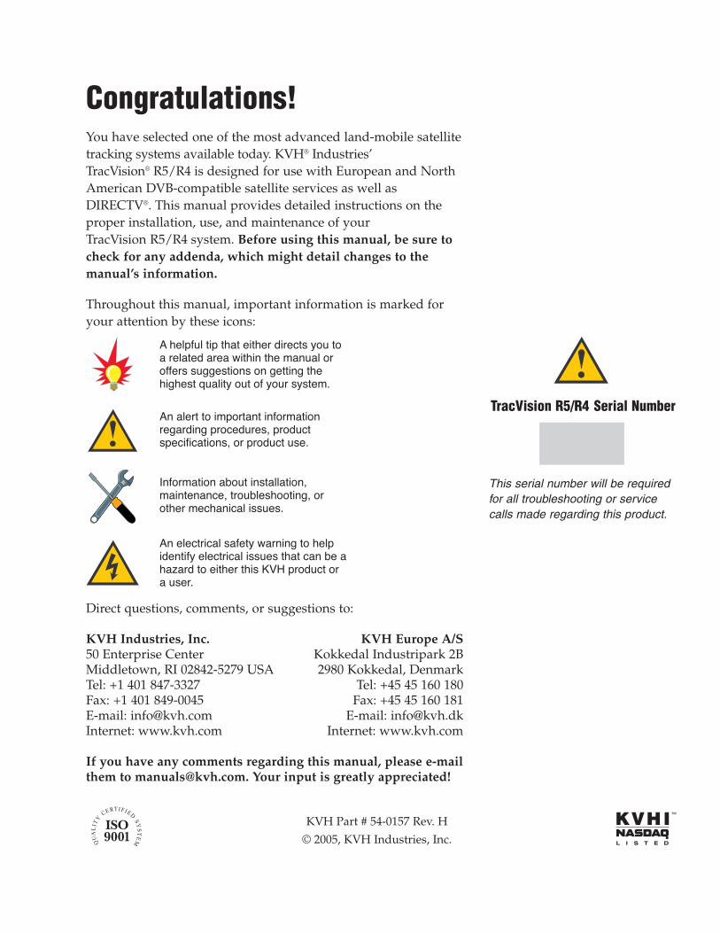
Congratulations!You have selected one of the most advanced land-mobile satellitetracking systems available today. KVH® Industries’ TracVision® R5/R4 is designed for use with European and NorthAmerican DVB-compatible satellite services as well asDIRECTV®. This manual provides detailed instructions on theproper installation, use, and maintenance of your TracVision R5/R4 system. Before using this manual, be sure tocheck for any addenda, which might detail changes to themanual’s information.
Throughout this manual, important information is marked foryour attention by these icons:
Direct questions, comments, or suggestions to:
KVH Industries, Inc. KVH Europe A/S50 Enterprise Center Kokkedal Industripark 2BMiddletown, RI 02842-5279 USA 2980 Kokkedal, DenmarkTel: +1 401 847-3327 Tel: +45 45 160 180Fax: +1 401 849-0045 Fax: +45 45 160 181E-mail: [email protected] E-mail: [email protected]: www.kvh.com Internet: www.kvh.com
If you have any comments regarding this manual, please e-mailthem to [email protected]. Your input is greatly appreciated!
A helpful tip that either directs you to a related area within the manual or offers suggestions on getting the highest quality out of your system.
An alert to important information regarding procedures, product specifications, or product use.
An electrical safety warning to help identify electrical issues that can be a hazard to either this KVH product or a user.
Information about installation, maintenance, troubleshooting, or other mechanical issues.
KVH Part # 54-0157 Rev. H
© 2005, KVH Industries, Inc.
TracVision R5/R4 Serial Number
This serial number will be requiredfor all troubleshooting or servicecalls made regarding this product.

TracVision® and KVH® are registered trademarks of KVH Industries, Inc.
DVB® (Digital Video Broadcasting) is a registered trademark of the DVB Project.
DIRECTV® is an official trademark of DIRECTV, Inc.
DISH Network™ is an official trademark of EchoStar Communications Corporation.
ExpressVu is a property of Bell ExpressVu, a wholly ownedsubsidiary of Bell Satellite Services.
Table of Contents1 Introduction . . . . . . . . . . . . . . . . . . . . . . . . . . . . . . . . .1-11.1 Digital Satellite Television . . . . . . . . . . . . . . . . . . . . . . . . . . . . . . .1-1
1.2 System Overview . . . . . . . . . . . . . . . . . . . . . . . . . . . . . . . . . . . . . .1-2
1.2.1 TracVision R5/R4 Components . . . . . . . . . . . . . . . . . . . . . . .1-3
1.2.2 Satellite TV Receiver . . . . . . . . . . . . . . . . . . . . . . . . . . . . . . .1-3
1.3 Materials Provided with TracVision R5/R4 . . . . . . . . . . . . . . . . . .1-4
1.3.1 Additional Materials Required for TracVision R5/R4 Use . . .1-5
2 Installation . . . . . . . . . . . . . . . . . . . . . . . . . . . . . . . . .2-12.1 Choosing the Best Location . . . . . . . . . . . . . . . . . . . . . . . . . . . . .2-3
2.2 Mounting the Antenna Unit . . . . . . . . . . . . . . . . . . . . . . . . . . . . . .2-4
2.3 Connecting System Components . . . . . . . . . . . . . . . . . . . . . . . . .2-8
2.3.1 Connecting the Antenna Data/Power Cable . . . . . . . . . . . . .2-9
2.3.2 Connecting to Vehicle Power . . . . . . . . . . . . . . . . . . . . . . . .2-10
2.3.3 Connecting the Receiver Ground Wire . . . . . . . . . . . . . . . .2-11
2.3.4 Installing the Switchplate . . . . . . . . . . . . . . . . . . . . . . . . . . .2-11
2.3.5 Connecting the Antenna RF Signal Cable tothe Receiver . . . . . . . . . . . . . . . . . . . . . . . . . . . . . . . . . .2-12
2.3.5.1 Installing Two Receivers and TVs (North American Systems Only) . . . . . . . . . . . . . . . . . . .2-12
2.3.5.2 Connecting Three or More Receivers and TVs (North American Systems Only) . . . . . . . . . . . . . . . . . . .2-13
2.3.6 Sealing the Cable Access Hole . . . . . . . . . . . . . . . . . . . . . .2-14
2.4 Activating the Receiver . . . . . . . . . . . . . . . . . . . . . . . . . . . . . . . .2-14
2.5 Selecting the Active Satellite . . . . . . . . . . . . . . . . . . . . . . . . . . . .2-15
2.5.1 Installing Your Selected Satellites . . . . . . . . . . . . . . . . . . . .2-16
2.5.2 Programming User-defined Satellites . . . . . . . . . . . . . . . . .2-19
2.6 Setting the Skew Angle (European Systems Only) . . . . . . . . . .2-24
2.7 Testing the System . . . . . . . . . . . . . . . . . . . . . . . . . . . . . . . . . . . .2-25
2.8 Configuring TracVision R5/R4 for Remote Satellite Dish Operation . . . . . . . . . . . . . . . . . . . . . . . . . . . . . . . .2-26
2.9 Changing Geographic Location . . . . . . . . . . . . . . . . . . . . . . . . .2-27
i54-0157 Rev. H
ii
3 Using Your TracVision R5/R4 . . . . . . . . . . . . . . . . . . . . .3-13.1 Turning On the System . . . . . . . . . . . . . . . . . . . . . . . . . . . . . . . . .3-1
3.2 Changing Channels and Switching Between Satellites . . . . . . .3-2
3.2.1 Using the Receiver Remote Control to Switch Between Satellites . . . . . . . . . . . . . . . . . . . . . . . . . . . . . . . . .3-2
3.2.2 Using the TV/SAT Switch to Switch Between Satellites . . . . . . . . . . . . . . . . . . . . . . . . . . . . . . . . .3-3
3.2.3 Using a PC to Switch Between Satellites . . . . . . . . . . . . . . .3-5
3.3 Watching Television . . . . . . . . . . . . . . . . . . . . . . . . . . . . . . . . . . . .3-6
3.4 DISH 500 Mode . . . . . . . . . . . . . . . . . . . . . . . . . . . . . . . . . . . . . . . .3-8
4 Troubleshooting . . . . . . . . . . . . . . . . . . . . . . . . . . . . . .4-14.1 Causes and Remedies for Common Operational Issues . . . . . .4-1
4.1.1 Blown Fuse or Improper Wiring . . . . . . . . . . . . . . . . . . . . . . .4-2
4.1.2 Incorrect Satellite Configuration . . . . . . . . . . . . . . . . . . . . . .4-2
4.1.3 Satellite Signal Blocked . . . . . . . . . . . . . . . . . . . . . . . . . . . . .4-2
4.1.4 Dew or Rain Pooling on Dome . . . . . . . . . . . . . . . . . . . . . . .4-3
4.1.5 Satellite Coverage Issue . . . . . . . . . . . . . . . . . . . . . . . . . . . .4-3
4.1.6 Vehicle Turning During Startup (TracVision R5 only) . . . . . .4-3
4.1.7 Incorrect or Loose RF Connectors . . . . . . . . . . . . . . . . . . . .4-4
4.1.8 Type of Multiswitch Used(North American Systems Only) . . . . . . . . . . . . . . . . . . . . . .4-4
4.1.9 Stationary Use Only (TracVision R4 only) . . . . . . . . . . . . . . .4-4
4.2 Receiver Troubleshooting . . . . . . . . . . . . . . . . . . . . . . . . . . . . . . .4-4
4.2.1 Receiver Wiring . . . . . . . . . . . . . . . . . . . . . . . . . . . . . . . . . . .4-4
4.2.2 Receiver Faulty . . . . . . . . . . . . . . . . . . . . . . . . . . . . . . . . . . .4-4
4.3 Antenna Gyro and LNB Faults . . . . . . . . . . . . . . . . . . . . . . . . . . . .4-5
4.4 Computer Diagnostics . . . . . . . . . . . . . . . . . . . . . . . . . . . . . . . . . .4-5
5 Maintenance . . . . . . . . . . . . . . . . . . . . . . . . . . . . . . . .5-15.1 Warranty/Service Information . . . . . . . . . . . . . . . . . . . . . . . . . . . .5-1
5.2 Preventive Maintenance . . . . . . . . . . . . . . . . . . . . . . . . . . . . . . . . .5-1
5.3 Replaceable Parts . . . . . . . . . . . . . . . . . . . . . . . . . . . . . . . . . . . . . .5-2

5.4 Field Replaceable Unit Procedures . . . . . . . . . . . . . . . . . . . . . . . .5-3
5.4.1 PCB Removal and Replacement . . . . . . . . . . . . . . . . . . . . . .5-5
5.4.2 RF Detector/DVB Decoder . . . . . . . . . . . . . . . . . . . . . . . . . .5-6
5.4.3 Antenna Gyro Assembly (TracVision R5 only) . . . . . . . . . . .5-7
5.4.4 Antenna LNB Replacement . . . . . . . . . . . . . . . . . . . . . . . . . .5-8
5.5 Preparation for Shipment . . . . . . . . . . . . . . . . . . . . . . . . . . . . . . . .5-9
Appendix A System Specifications . . . . . . . . . . . . . . . . . . .A-1
Appendix B Switchplate Template . . . . . . . . . . . . . . . . . . .B-1
iii54-0157 Rev. H

1 Introduction
1.1 Digital Satellite TelevisionYour new TracVision R5/R4 satellite antenna is fully compatiblewith the Digital Video Broadcasting (DVB) satellites, which usethe international standard for digital TV transmission, as well asDigital Satellite Service (DSS) services, such as DIRECTV. As aresult, you will be able to receive and decode signals from yourchosen satellite services with the proper programming andhardware (e.g., the satellite TV receiver).
Your TracVision R5/R4 comes with a pre-programmed “satellitelibrary” of European and North American satellite services.When configuring the TracVision R5/R4, you may choose a pairof satellites from the library to be active in the system and withyour receiver. For the antenna to receive signals from twosatellites, they must be within 10° longitude of each other inorbit. As a result, certain satellites can only be paired with certainother satellites. Tables 1-1 and 1-2 list the possible satellite pairsthat may be selected in North America and Europe. If the satelliteservice you wish to receive is not already in the satellite library, youmay also add two additional satellites of your choice to the library.
1-1
Introduction
54-0157 Rev. H
Table 1-1Available N. American SatellitePairs (U.S.-style LNB required)
DSS_101 3 3 3
DSS_119 3 3 3
Echo_61 3 3 3 3
Echo_110 3 3 3 3 3
Echo_119 3 3 3 3 3
Echo_148 3 3 3 3
Expressvu 3 3 3 3 3 3 3
ExpressTV 3 3 3 3 3 3 3
DSS_101 DSS_119 Echo_61 Echo_110 Echo_119 Echo_148 Expressvu ExpressTV
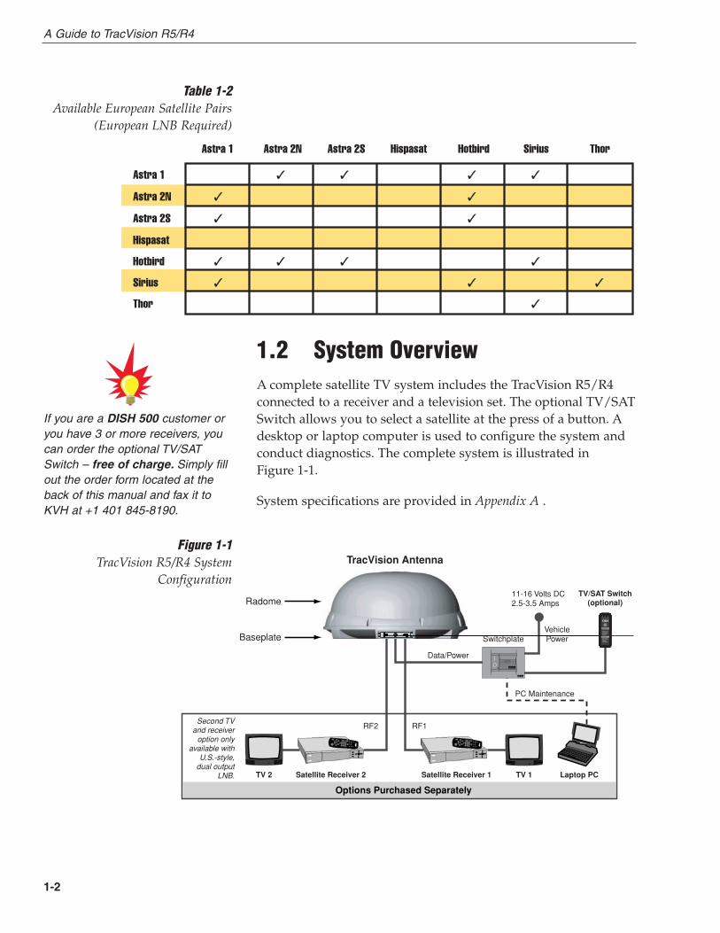
1.2 System OverviewA complete satellite TV system includes the TracVision R5/R4connected to a receiver and a television set. The optional TV/SATSwitch allows you to select a satellite at the press of a button. Adesktop or laptop computer is used to configure the system andconduct diagnostics. The complete system is illustrated in Figure 1-1.
System specifications are provided in Appendix A .
1-2
A Guide to TracVision R5/R4
11-16 Volts DC 2.5-3.5 Amps
Satellite Receiver 1
RF2
Options Purchased Separately
TV 1
Data/Power
Vehicle�PowerSwitchplate
PC Maintenance
Satellite Receiver 2TV 2 Laptop PC
TracVision Antenna
RF1
Baseplate
Radome
Second TV and receiver
option only available with
U.S.-style, dual output
LNB.
TV/SAT Switch (optional)
Sat A Error
Other Indicators:
• Both blinkinggreen: initializing
• Error lightblinking red:system problem
Changing Satellites:
1. Push Select button
2. Wait while Sat A orB blinks green
3. Ready when Sat Aor Sat B stayssolid green
Sat B
Select
Figure 1-1TracVision R5/R4 System
Configuration
If you are a DISH 500 customer oryou have 3 or more receivers, youcan order the optional TV/SATSwitch – free of charge. Simply fillout the order form located at theback of this manual and fax it toKVH at +1 401 845-8190.
Astra 1 3 3 3 3
Astra 2N 3 3
Astra 2S 3 3
Hispasat
Hotbird 3 3 3 3
Sirius 3 3 3
Thor 3
Astra 1 Astra 2N Astra 2S Hispasat Hotbird Sirius Thor
Table 1-2Available European Satellite Pairs
(European LNB Required)

In-motion Tracking (TracVision R5 only)
The TracVision R5 employs a state-of-the-art actively stabilizedantenna system. Once the satellite is acquired, the antenna gyrocontinuously measures your vehicle’s motion and position, andtransmits commands to the antenna motors to keep the antennapointed at the satellite at all times.
1.2.1 TracVision R5/R4 Components
The antenna unit includes the antenna positioning mechanism,signal front end, power supply, and control elements. Theantenna is a parabolic dish mounting a low noise block (LNB)converter with a built-in preamplifier. The Europeanconfiguration includes a single-output LNB while the NorthAmerican system uses a dual-output LNB. A molded ABSradome encloses the fiberglass baseplate and is secured in placewith standard fasteners. Connectors on the back of the baseplatejoin the power, signal, and control cabling from units inside thevehicle.
1.2.2 Satellite TV Reciever - Sold Separately
The receiver (purchased separately) receives satellite signals fromthe antenna unit for signal processing and channel selection, andsends the signals to the TV set for viewing. Please refer to theUser’s Manual provided with your selected receiver for completeoperating instructions.
1-3
Introduction
54-0157 Rev. H
The dual-output LNB in the NorthAmerican systems allows tworeceiver/TV pairs to be connecteddirectly to the antenna. Three ormore pairs can be connected to thesystem if an active multiswitch isused. Section 2.3.5, “Connectingthe Antenna RF Signal Cable to theReceiver,” provides installationdirections for each of these options.
Before you can start watchingsatellite TV using your TracVisionantenna, you will need to activateyour receiver. Refer to Section 2.4,“Activating the Receiver,” for moredetails.
KVH offers an upgrade kit (KVHPart #02-1026) that adds in-motiontracking capability to the TracVision R4, allowing you toreceive satellite signals while onthe move.
1.3 Materials Provided withTracVision R5/R4
Table 1-3 lists the units, cables, and materials packed in theTracVision R5/R4 package by name and KVH part number.
Component KVH Part No.
Antenna Unit (TracVision R5), comprising: 01-0225-19†
01-0225-22††
01-0225-25†††
01-0225-28††††
Baseplate Assembly (TracVision R5) 02-1245-01*02-1245-03**
Radome Assembly (TracVision R5) 02-0953-03
Antenna Unit (TracVision R4), comprising: 01-0225-21†
01-0225-27†††
01-0225-30††††
01-0225-24††
Baseplate Assembly (TracVision R4) 02-1245-02*02-1245-04**
Radome Assembly (TracVision R4) 02-0953-05
RF Cable (28 ft/8.5 m) 32-0417-28
Data/Power Cable (28 ft/8.5 m) 32-0730-28
PC Cable (6 ft/1.8 m) 32-0628-06
Kitpack*** 72-0101
Owner’s Manual 54-0157
Receiver Ground Wire 32-0583-50
Switchplate 02-1023-01
TV/SAT Switch (optional) 01-0245
† European TracVision R5/R4 system†† North American TracVision R5/R4 system (set to DIRECTV)††† North American TracVision R5/R4 system (set to DISH Network)†††† North American TracVision R5/R4 system (set to ExpressVu)* Baseplate assembly with single-output LNB** Baseplate assembly with dual-output LNB *** A complete listing of kitpack contents is provided in Table 2-2.
1-4
A Guide to TracVision R5/R4
Table 1-3TracVision R5/R4 Packing List
Cables for the TracVision R5/R4 arestored beneath the antenna unitduring shipping.
1.3.1 Additional Materials Required forTracVision R5/R4 Use
To make full use of your new TracVision R5/R4 and receivesatellite TV on the road, you will need to provide/purchase thefollowing:
• Television
• Appropriate receiver for your selected satellite TV service
1-5
Introduction
54-0157 Rev. H
In North America, you canpurchase and/or activate a receiverdirectly from KVH. Call KVH at 1-888-584-4163 for details.

2-1
Installation
54-0157 Rev. H
2 InstallationYour TracVision R5/R4 is designed for simple installation andsetup. Just follow these easy steps:
Step Refer to Section...
1. Choose the hardware locations 2.1
2. Mount the antenna unit 2.2
3. Connect system components 2.3
4. Activate the receiver 2.4
5. Select active satellite 2.5
6. Set the skew angle (Europe only) 2.6
7. Check out system 2.7
8. Configure for remote dish use 2.8
Tools and Materials Required
• Electric drill
• 3⁄16" (5 mm), 5⁄32" (4 mm), and 3⁄32" (2.5 mm) drill bitsand 3⁄4" (19 mm) hole saw and auger bit
• 1⁄2" wrench
• #2 Phillips and #0 flat tip screwdrivers
• RG-6 or RG-11 (75 ohms) RF cable (if installingtwo RF cables - refer to Section 2.3.5 for details)
• Silicone sealant, RTV, or Sikaflex
• 7⁄16" open end wrench
• Construction adhesive (e.g., Liquid Nails)
• Rivet gun and 3⁄16" (5 mm) rivets (or other fastenersuitable for your specific roof construction)
• PC with Windows HyperTerminal or downloadthe KVH Flash Update Wizard (available for freeat www.kvh.com/wizard)
Plan the entire installation beforeproceeding! Take into accountcomponent placement, cablerunning distances between units,and accessibility to the equipmentafter installation.
Table 2-1Installation Process

2-2
A Guide to TracVision R5/R4
Kitpack Contents
Table 2-2 lists the materials provided in the kitpack.
Part Qty. KVH Part No.
Tie-wraps 5 22-0013
Clamshell ventilator 1 19-0230
#6 x 3⁄4" thread-forming screws 3 14-0298-12
1⁄4"-20 x 5⁄8" hex screws 4 14-0250-10
1⁄4" flat washers 4 14-0251
3⁄8" hole plugs 2 19-0282-06
Table 2-2Kitpack Contents
2-3
Installation
54-0157 Rev. H
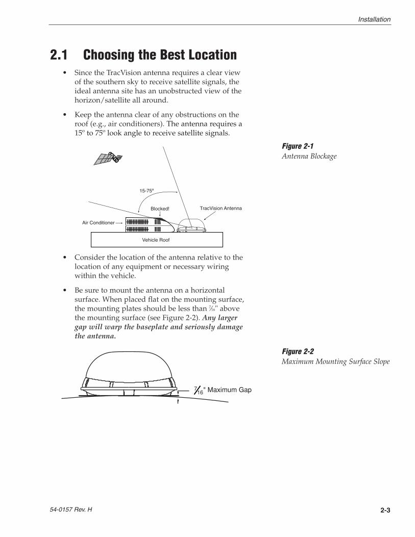
2.1 Choosing the Best Location• Since the TracVision antenna requires a clear view
of the southern sky to receive satellite signals, theideal antenna site has an unobstructed view of thehorizon/satellite all around.
• Keep the antenna clear of any obstructions on theroof (e.g., air conditioners). The antenna requires a15º to 75º look angle to receive satellite signals.
• Consider the location of the antenna relative to thelocation of any equipment or necessary wiringwithin the vehicle.
• Be sure to mount the antenna on a horizontalsurface. When placed flat on the mounting surface,the mounting plates should be less than 7⁄16" abovethe mounting surface (see Figure 2-2). Any largergap will warp the baseplate and seriously damagethe antenna.
Blocked! TracVision Antenna
Air Conditioner
Vehicle Roof
Figure 2-1Antenna Blockage
" Maximum Gap716
Figure 2-2Maximum Mounting Surface Slope
2-4
A Guide to TracVision R5/R4
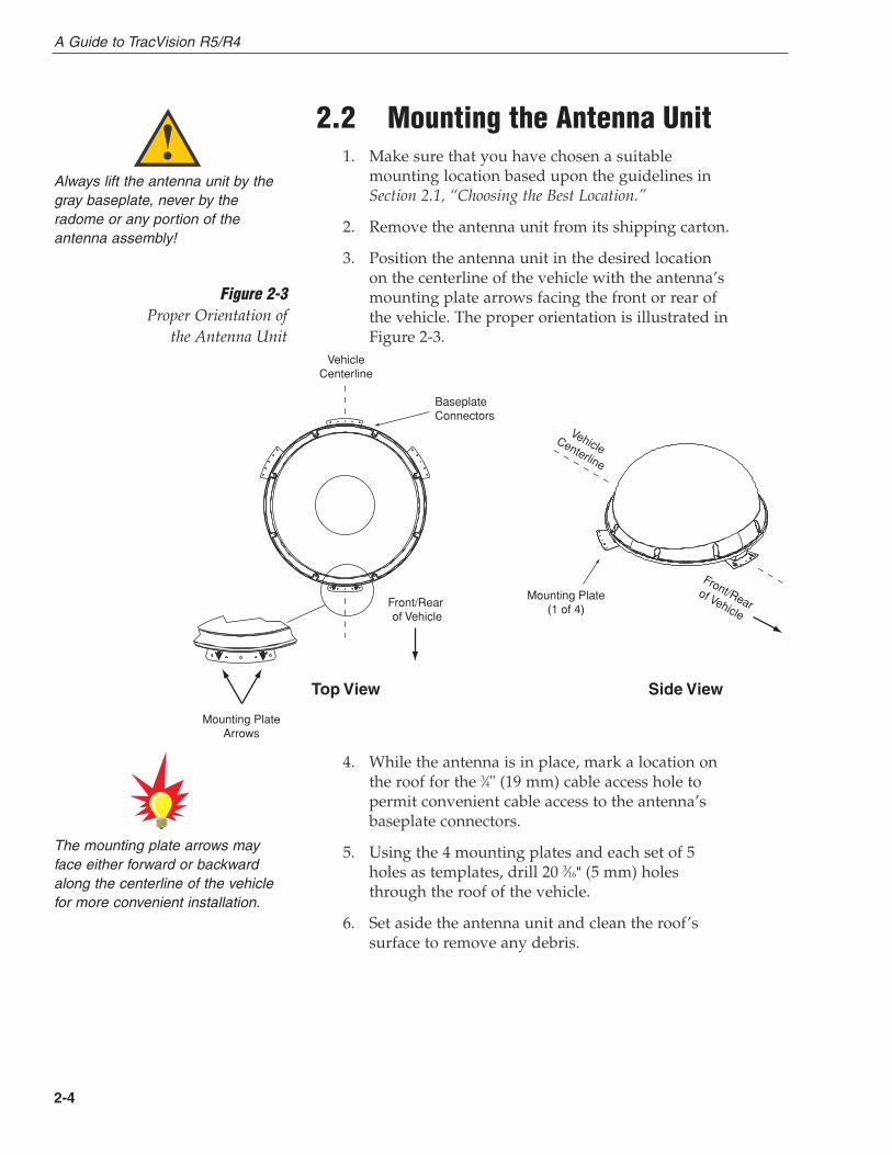
2.2 Mounting the Antenna Unit1. Make sure that you have chosen a suitable
mounting location based upon the guidelines inSection 2.1, “Choosing the Best Location.”
2. Remove the antenna unit from its shipping carton.
3. Position the antenna unit in the desired locationon the centerline of the vehicle with the antenna’smounting plate arrows facing the front or rear ofthe vehicle. The proper orientation is illustrated inFigure 2-3.
4. While the antenna is in place, mark a location onthe roof for the 3⁄4" (19 mm) cable access hole topermit convenient cable access to the antenna’sbaseplate connectors.
5. Using the 4 mounting plates and each set of 5holes as templates, drill 20 3⁄16" (5 mm) holesthrough the roof of the vehicle.
6. Set aside the antenna unit and clean the roof’ssurface to remove any debris.
Always lift the antenna unit by thegray baseplate, never by theradome or any portion of theantenna assembly!
The mounting plate arrows mayface either forward or backwardalong the centerline of the vehiclefor more convenient installation.
Vehicle�Centerline
VehicleCenterline
Front/Rear� of Vehicle
Front/Rearof Vehicle
Top View Side View
Mounting Plate�(1 of 4)
Baseplate Connectors
Mounting Plate�Arrows
Figure 2-3Proper Orientation of
the Antenna Unit
2-5
Installation
54-0157 Rev. H
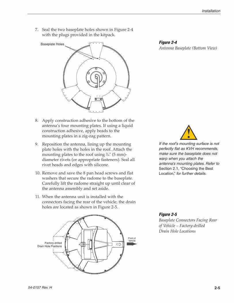
7. Seal the two baseplate holes shown in Figure 2-4with the plugs provided in the kitpack.
8. Apply construction adhesive to the bottom of theantenna’s four mounting plates. If using a liquidconstruction adhesive, apply beads to themounting plates in a zig-zag pattern.
9. Reposition the antenna, lining up the mountingplate holes with the holes in the roof. Attach themounting plates to the roof using 3⁄16" (5 mm)-diameter rivets (or appropriate fasteners). Seal allrivet heads and edges with silicone.
10. Remove and save the 8 pan head screws and flatwashers that secure the radome to the baseplate.Carefully lift the radome straight up until clear ofthe antenna assembly and set aside.
11. When the antenna unit is installed with theconnectors facing the rear of the vehicle, the drainholes are located as shown in Figure 2-5.
Figure 2-5Baseplate Connectors Facing Rear of Vehicle – Factory-drilledDrain Hole Locations
If the roof’s mounting surface is notperfectly flat as KVH recommends,make sure the baseplate does notwarp when you attach theantenna’s mounting plates. Refer toSection 2.1, “Choosing the BestLocation,” for further details.
Factory-drilledDrain Hole Positions
Front ofVehicle
Recommended3/16" (5 mm)
Drain Hole Positions
Drain Hole Angle(relative to baseplate)
Front ofVehicle
Angle of Hole, relative to front
Angle of Hole, relative to front
Figure 2-4Antenna Baseplate (Bottom View)
Baseplate Holes
2-6
A Guide to TracVision R5/R4
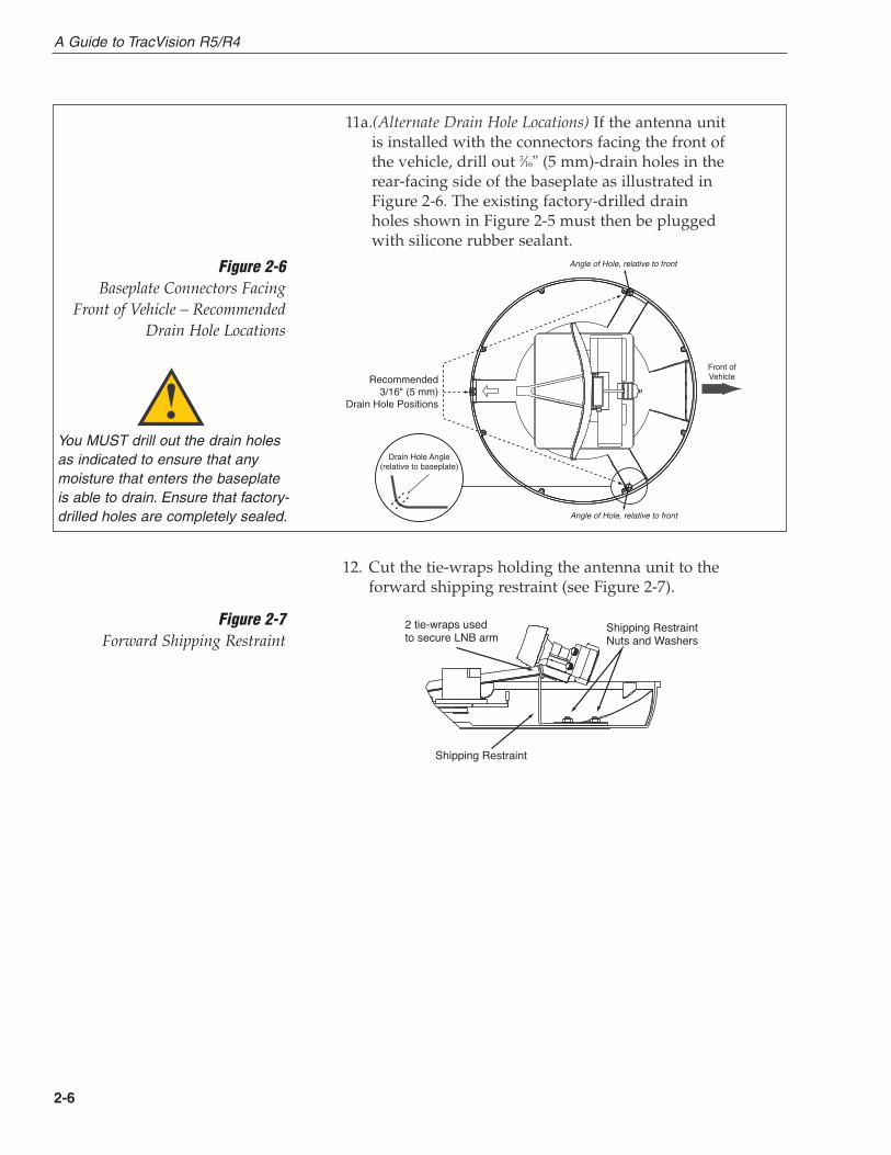
12. Cut the tie-wraps holding the antenna unit to theforward shipping restraint (see Figure 2-7).
2 tie-wraps used to secure LNB arm
Shipping Restraint
Shipping RestraintNuts and Washers
Figure 2-7Forward Shipping Restraint
Figure 2-6Baseplate Connectors Facing
Front of Vehicle – Recommended Drain Hole Locations
You MUST drill out the drain holesas indicated to ensure that anymoisture that enters the baseplateis able to drain. Ensure that factory-drilled holes are completely sealed.
11a.(Alternate Drain Hole Locations) If the antenna unitis installed with the connectors facing the front ofthe vehicle, drill out 3⁄16" (5 mm)-drain holes in therear-facing side of the baseplate as illustrated inFigure 2-6. The existing factory-drilled drainholes shown in Figure 2-5 must then be pluggedwith silicone rubber sealant.
Factory-drilledDrain Hole Positions
Front ofVehicle
Recommended3/16" (5 mm)
Drain Hole Positions
Drain Hole Angle(relative to baseplate)
Front ofVehicle
Angle of Hole, relative to front
Angle of Hole, relative to front

2-7
Installation
54-0157 Rev. H
13. Remove the nuts and washers securing theshipping restraints to the baseplate. The shippingrestraints are pictured in Figure 2-8.
14. Remove the shipping restraints and replace thenuts and washers into their original positions. Allnuts and washers removed in Step 13 must bereinstalled. These nuts and washers secure thebaseplate to the mounting plates.
15. Place the radome onto the baseplate (labels facingthe sides of the vehicle) and secure in place usingthe 8 pan head screws and flat washers removedin Step 10.
16. Drill the cable access hole (marked in Step 4) in thevehicle’s roof.
Rotating Plate�Shipping Restraint
Rotating Plate�Shipping Restraint
Forward Shipping�Restraint for�LNB Bracket
Figure 2-8TracVision R5/R4 ShippingRestraints (Top View)
Do not discard the shippingrestraints, washers, or the nuts.They should be saved for futureuse in case the antenna unit needsto be removed and shipped toanother location. Four 1⁄4˝ x 5⁄8˝ hexhead screws have been provided inthe kitpack for shipping as the boltsused to hold the shipping restraintsduring initial shipping are integralparts of the mounting plates.
2-8
A Guide to TracVision R5/R4
2.3 Connecting System ComponentsThe following sections provide instructions for properly wiringthe antenna unit to the components inside the vehicle.
Locating the Switchplate
A switchplate has been provided to serve as the hub of theTracVision R5/R4 wiring (with the exception of the RF cable,which will be connected to the receiver). This switchplateincludes an ON/OFF switch and a DB9 maintenance port foreasy access to the antenna unit’s software and diagnostics.Follow the steps below to select and prepare the switchplatemounting location.
1. Select a location to mount the TracVision R5/R4switchplate. It should be installed in a dry, flatlocation within reach of the cables that willconnect to the antenna unit.
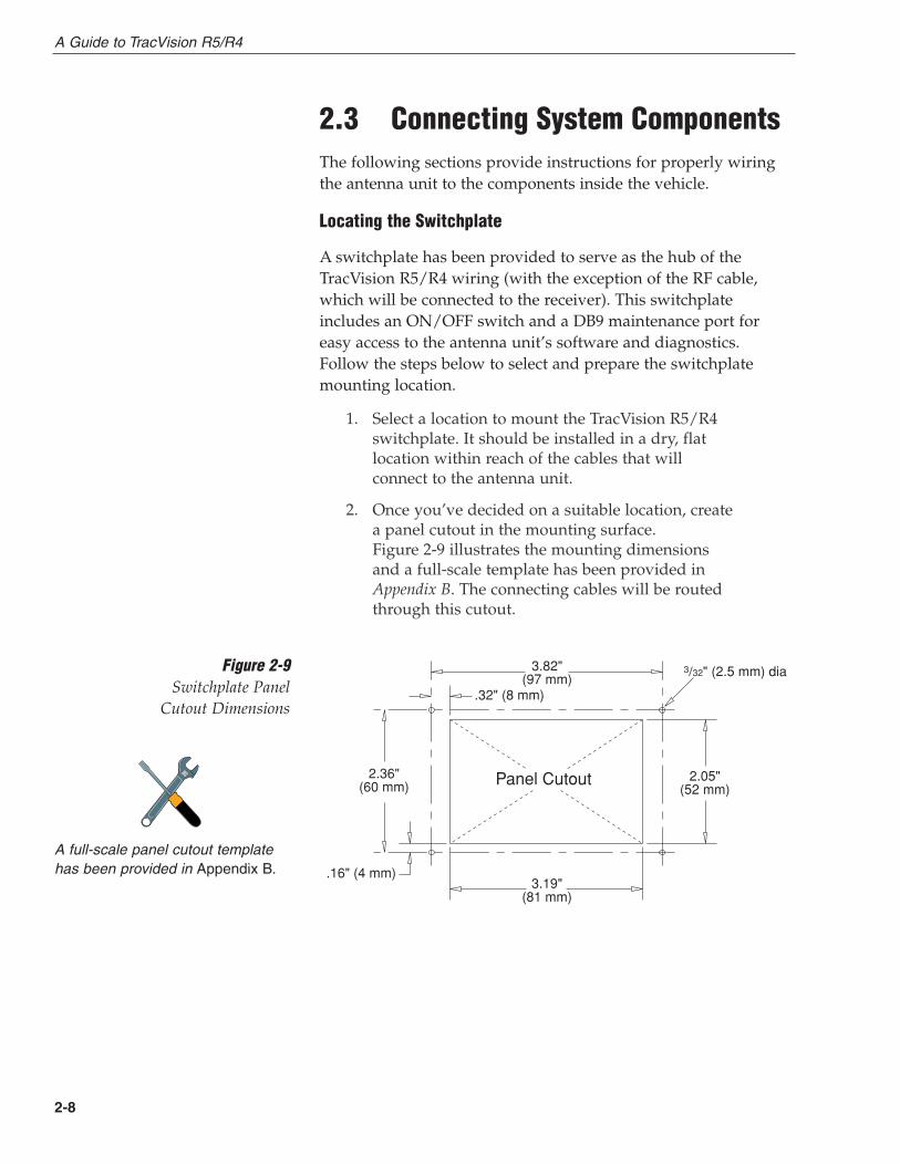
2. Once you’ve decided on a suitable location, createa panel cutout in the mounting surface. Figure 2-9 illustrates the mounting dimensionsand a full-scale template has been provided inAppendix B. The connecting cables will be routedthrough this cutout.
3.82" (97 mm)
.32" (8 mm)
2.36" (60 mm)
.16" (4 mm)3.19"
(81 mm)
2.05" (52 mm)
Panel Cutout
3/32" (2.5 mm) diaFigure 2-9Switchplate Panel
Cutout Dimensions
A full-scale panel cutout templatehas been provided in Appendix B.
2-9
Installation
54-0157 Rev. H
2.3.1 Connecting the Antenna Data/PowerCable
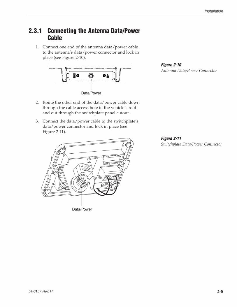
1. Connect one end of the antenna data/power cableto the antenna’s data/power connector and lock inplace (see Figure 2-10).
2. Route the other end of the data/power cable downthrough the cable access hole in the vehicle’s roofand out through the switchplate panel cutout.
3. Connect the data/power cable to the switchplate’sdata/power connector and lock in place (seeFigure 2-11).
Data/Power
Figure 2-10Antenna Data/Power Connector
Data/Power
Figure 2-11Switchplate Data/Power Connector
2-10
A Guide to TracVision R5/R4
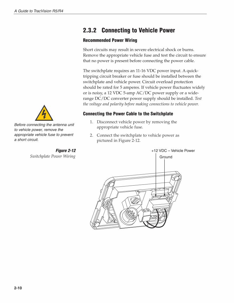
2.3.2 Connecting to Vehicle Power
Recommended Power Wiring
Short circuits may result in severe electrical shock or burns.Remove the appropriate vehicle fuse and test the circuit to ensurethat no power is present before connecting the power cable.
The switchplate requires an 11-16 VDC power input. A quick-tripping circuit breaker or fuse should be installed between theswitchplate and vehicle power. Circuit overload protectionshould be rated for 5 amperes. If vehicle power fluctuates widelyor is noisy, a 12 VDC 5-amp AC/DC power supply or a wide-range DC/DC converter power supply should be installed. Testthe voltage and polarity before making connections to vehicle power.
Connecting the Power Cable to the Switchplate
1. Disconnect vehicle power by removing theappropriate vehicle fuse.
2. Connect the switchplate to vehicle power aspictured in Figure 2-12.
Before connecting the antenna unitto vehicle power, remove theappropriate vehicle fuse to preventa short circuit.
+12 VDC – Vehicle Power
Ground
Figure 2-12Switchplate Power Wiring

2-11
Installation
54-0157 Rev. H
2.3.3 Connecting the Receiver Ground Wire
A grounding wire (Cable #32-0583-50) has been provided toconnect your receiver to a suitable ground and protect thesystem. Attach the grounding wire to any suitable screw on therear panel of the receiver with a good contact with the receiverchassis. The other end should be connected to a suitable ground.
2.3.4 Installing the Switchplate
After completing the switchplate wiring process, you must installthe switchplate itself. This process, detailed in the followingsteps, is illustrated in Figure 2-13.
1. Fit the switchplate assembly and support frameinto the panel cutout made in Step 2 of Section 2.3,“Connecting System Components,” and flush to themounting surface.
2. Drill out four 5⁄32" (4 mm) holes in the countersunksettings in the switchplate support frame.
3. Drill four 3⁄32" (2.5 mm) holes in the mountingsurface using the countersunk holes in the supportframe as the template. Secure the support frameand switchplate assembly to the mounting surfaceusing four #6 self-cutting screws.
4. Snap the front cover into place to cover the screwsand support frame.
5. Reinstall the vehicle fuse removed in Step 1 ofSection 2.3.2, “Connecting to Vehicle Power.”
3.82"�(97 mm)
2.36"�(60 mm) 2.05"�
(52 mm)
3.19"�(81 mm)
A. Panel Cutout
B. Support Frame
C. Front Cover
5/32" (4 mm)3/32" (2.5 mm)
Figure 2-13Mounting the Switchplate Support Frame and Front Cover
Before securing the switchplate tothe mounting surface, be sure tostrain-relieve the wires connectingto the switchplate connectors.Several tie-wraps have beenprovided to aid in strain-relievingthe wires.
2-12
A Guide to TracVision R5/R4
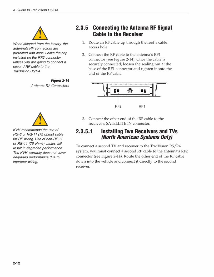
2.3.5 Connecting the Antenna RF Signal Cable to the Receiver
1. Route an RF cable up through the roof’s cableaccess hole.
2. Connect the RF cable to the antenna’s RF1connector (see Figure 2-14). Once the cable issecurely connected, loosen the sealing nut at thebase of the RF1 connector and tighten it onto theend of the RF cable.
3. Connect the other end of the RF cable to thereceiver’s SATELLITE IN connector.
2.3.5.1 Installing Two Receivers and TVs (North American Systems Only)
To connect a second TV and receiver to the TracVision R5/R4system, you must connect a second RF cable to the antenna’s RF2connector (see Figure 2-14). Route the other end of the RF cabledown into the vehicle and connect it directly to the secondreceiver.
KVH recommends the use of RG-6 or RG-11 (75 ohms) cable for RF wiring. Use of non-RG-6 or RG-11 (75 ohms) cables willresult in degraded performance.The KVH warranty does not coverdegraded performance due toimproper wiring.
When shipped from the factory, theantenna’s RF connectors areprotected with caps. Leave the capinstalled on the RF2 connectorunless you are going to connect asecond RF cable to the TracVision R5/R4.
RF2 RF1
Figure 2-14Antenna RF Connectors
2-13
Installation
54-0157 Rev. H
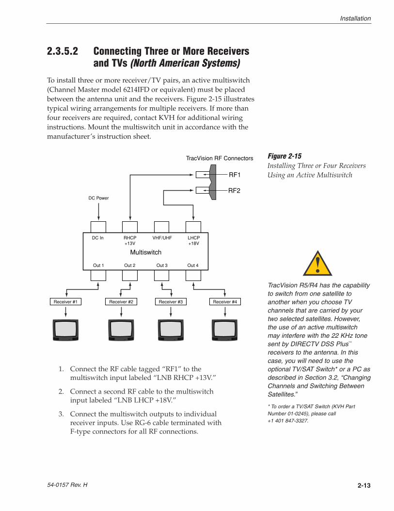
2.3.5.2 Connecting Three or More Receiversand TVs (North American Systems)
To install three or more receiver/TV pairs, an active multiswitch(Channel Master model 6214IFD or equivalent) must be placedbetween the antenna unit and the receivers. Figure 2-15 illustratestypical wiring arrangements for multiple receivers. If more thanfour receivers are required, contact KVH for additional wiringinstructions. Mount the multiswitch unit in accordance with themanufacturer’s instruction sheet.
1. Connect the RF cable tagged “RF1” to themultiswitch input labeled “LNB RHCP +13V.”
2. Connect a second RF cable to the multiswitchinput labeled “LNB LHCP +18V.”
3. Connect the multiswitch outputs to individualreceiver inputs. Use RG-6 cable terminated with F-type connectors for all RF connections.
Multiswitch
DC In RHCP +13V
VHF/UHF LHCP +18V
Out 1 Out 2 Out 3 Out 4
DC Power
Receiver #1 Receiver #2 Receiver #4Receiver #3
TracVision RF Connectors
RF1
RF2
Figure 2-15Installing Three or Four ReceiversUsing an Active Multiswitch
TracVision R5/R4 has the capabilityto switch from one satellite toanother when you choose TVchannels that are carried by yourtwo selected satellites. However,the use of an active multiswitchmay interfere with the 22 KHz tonesent by DIRECTV DSS Plus™
receivers to the antenna. In thiscase, you will need to use theoptional TV/SAT Switch* or a PC asdescribed in Section 3.2, “ChangingChannels and Switching BetweenSatellites.”
* To order a TV/SAT Switch (KVH PartNumber 01-0245), please call +1 401 847-3327.
4. Terminate all unused output connectors with 75 ohm DC blocks (Channel Master #7184, RadioShack #15-1259 or equivalent).
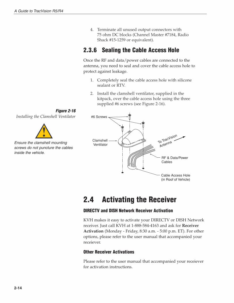
2.3.6 Sealing the Cable Access Hole
Once the RF and data/power cables are connected to theantenna, you need to seal and cover the cable access hole toprotect against leakage.
1. Completely seal the cable access hole with siliconesealant or RTV.
2. Install the clamshell ventilator, supplied in thekitpack, over the cable access hole using the threesupplied #6 screws (see Figure 2-16).
2.4 Activating the ReceiverDIRECTV and DISH Network Receiver Activation
KVH makes it easy to activate your DIRECTV or DISH Networkreceiver. Just call KVH at 1-888-584-4163 and ask for ReceiverActivation (Monday - Friday, 8:30 a.m. - 5:00 p.m. ET). For otheroptions, please refer to the user manual that accompanied yourreceiever.
Other Receiver Activations
Please refer to the user manual that accompanied your receieverfor activation instructions.
2-14
A Guide to TracVision R5/R4
Clamshell�Ventilator
#6 Screws
Cable Access Hole (in Roof of Vehicle)
RF & Data/Power�Cables
To TracVision
Antenna
Figure 2-16Installing the Clamshell Ventilator
Ensure the clamshell mountingscrews do not puncture the cablesinside the vehicle.
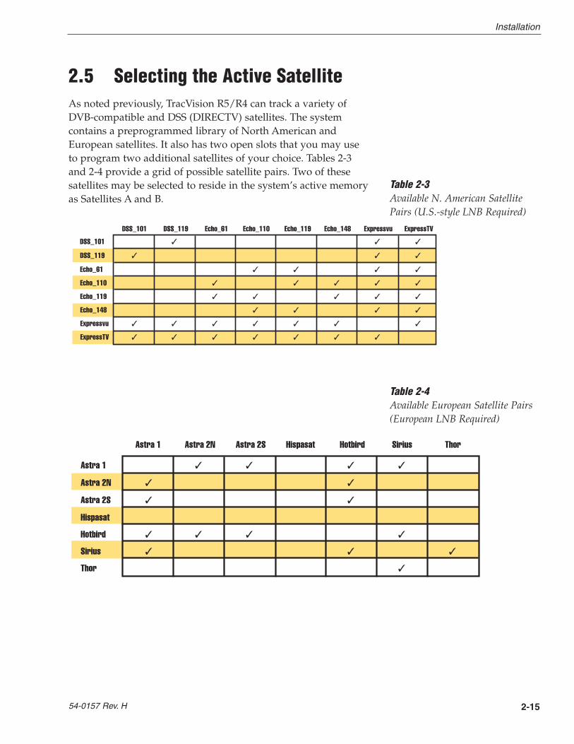
2.5 Selecting the Active SatelliteAs noted previously, TracVision R5/R4 can track a variety ofDVB-compatible and DSS (DIRECTV) satellites. The systemcontains a preprogrammed library of North American andEuropean satellites. It also has two open slots that you may useto program two additional satellites of your choice. Tables 2-3and 2-4 provide a grid of possible satellite pairs. Two of thesesatellites may be selected to reside in the system’s active memoryas Satellites A and B.
2-15
Installation
54-0157 Rev. H
DSS_101 3 3 3
DSS_119 3 3 3
Echo_61 3 3 3 3
Echo_110 3 3 3 3 3
Echo_119 3 3 3 3 3
Echo_148 3 3 3 3
Expressvu 3 3 3 3 3 3 3
ExpressTV 3 3 3 3 3 3 3
DSS_101 DSS_119 Echo_61 Echo_110 Echo_119 Echo_148 Expressvu ExpressTV
Table 2-3Available N. American SatellitePairs (U.S.-style LNB Required)
Table 2-4Available European Satellite Pairs(European LNB Required)
Astra 1 3 3 3 3
Astra 2N 3 3
Astra 2S 3 3
Hispasat
Hotbird 3 3 3 3
Sirius 3 3 3
Thor 3
Astra 1 Astra 2N Astra 2S Hispasat Hotbird Sirius Thor

The satellites listed in TracVision R5/R4 satellite library will besufficient for most users. However, if you wish to install one ortwo user-defined satellites, proceed to Section 2.5.2, “ProgrammingUser-defined Satellites.” After configuring the user-definedsatellites, return to the satellite installation process in Section 2.5.1, “Installing Your Selected Satellites.”
2.5.1 Installing Your Selected Satellites
When you first connect to the system, it is preprogrammed withone of the following default satellite assignments:
• Europe: Astra 1 (Sat. A) and Hotbird (Sat. B)
• N. America (US DIRECTV): DSS_101 (Sat. A) and DSS_119 (Sat. B)
• N. America (US DISH Network/ExpressVu):Echo_119 (Sat. A) and Expressvu (Sat. B)
Should you wish to track a different satellite (either from thesatellite library or a user-defined satellite), you must instruct theantenna which satellites will be in the active satellite pair.
Connecting to the TracVision R5/R4 Maintenance Port
To do so, it is necessary to connect a PC to the maintenance porton the front of the switchplate. To configure the antenna, you willneed to use the KVH Flash Update Wizard or WindowsHyperTerminal. Use the settings appropriate to your application.(You can download the KVH Flash Update Wizard atwww.kvh.com/wizard)
1. Connect one end of the PC data cable to the DB9maintenance port connector on the switchplate.Connect the other end to the serial port to your PC(a 9-pin/25-pin connector adapter may be neededfor some PCs).
2-16
A Guide to TracVision R5/R4
To receive DISH 500 service, youwill need to install the following twosatellites:Echo_119 & Echo_110
Maintenance Port (DB9)
Figure 2-17Connecting to the TracVision
R5/R4 Maintenance Port
The satellite configuration onyour receiver must match thesatellite setting on the TracVisionR5/R4 system.
Satellite A on the TracVision R5/R4must be the same satellite asReceiver Alternative 1 (or A, basedon your receiver and must beassigned the Receiver DiSEqC 1setting.*
Satellite B on the TracVision R5/R4must be the same satellite asReceiver Alternative 2 (or B, basedon your receiver) and must beassigned the Receiver DiSEqC 2setting.*
Refer to your receiver user manualfor complete instructions for yourreceiver.
* DiSEqC settings apply only to Europeansystems.

2. If you are using HyperTerminal, openHyperTerminal and establish the followingsettings:
• Bits per second: 9600
• Data bits: 8
• Parity: None
• Stop bits: 1
• Flow control: None
If you are using the KVH Flash Update Wizard,double-click the “KVH Flash Update Wizard”shortcut on your computer’s desktop to start thewizard. Then go to the “Select board to flash”screen. You do not need to flash the antenna toconfigure the satellites; you will simply entercommands in the “Command” box.
3. Apply power to the TracVision R5/R4 system andallow the system to complete full initialization.Data should be scrolling on the PC display toidentify any system problems detected. If no datais seen, recheck your connections and the terminalsoftware setup.
Installing the Satellite of Choice from the Satellite Library
Once the data connection has been made between the PC and theTracVision R5/R4, you must assign the satellites you wish tohave in the satellite pair by typing the following commands. (Ifyou are using HyperTerminal, type the commands in theHyperTerminal window. If you are using the KVH Flash UpdateWizard, type the commands in the “Command” box.)
1. Type HALT and press Enter to place the antenna inIdle Mode.
2. Select which preprogrammed satellites you wishto assign. Table 2-5 lists the satellite names that arein the preprogrammed North American andEuropean satellite library.
2-17
Installation
54-0157 Rev. H
Satellite Install Name
North American Satellites
DSS 101ºW DSS_101
DSS 119ºW DSS_119
EchoStar 61ºW Echo_61
EchoStar 110ºW Echo_110
EchoStar 119ºW Echo_119
EchoStar 148ºW Echo_148
ExpressVu Expressvu
ExpressTV ExpressTV
European Satellites
ASTRA1 19.2ºE ASTRA1
ASTRA2N 28.2ºE ASTRA2N
ASTRA2S 28.2ºE ASTRA2S
Hispasat 30.0ºW HISPASAT
Hotbird 13.0ºE HOTBIRD
Sirius 5.0ºE SIRIUS
Thor 0.8ºW THOR
Other Installation Designations
User-defined 1 USER1*
User-defined 2 USER2*
None None
* USER1 and USER2 will only beavailable if one or two user-definedsatellites have been added to thelibrary as detailed in Section 2.5.2,“Programming User-defined Satellites.”
Table 2-5Satellite Installation Names
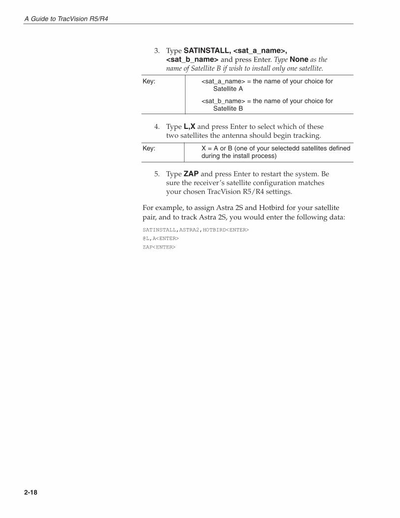
3. Type SATINSTALL, <sat_a_name>,<sat_b_name> and press Enter. Type None as thename of Satellite B if wish to install only one satellite.
Key: <sat_a_name> = the name of your choice for Satellite A
<sat_b_name> = the name of your choice for Satellite B
4. Type L,X and press Enter to select which of thesetwo satellites the antenna should begin tracking.
Key: X = A or B (one of your selectedd satellites definedduring the install process)
5. Type ZAP and press Enter to restart the system. Besure the receiver’s satellite configuration matchesyour chosen TracVision R5/R4 settings.
For example, to assign Astra 2S and Hotbird for your satellitepair, and to track Astra 2S, you would enter the following data:
SATINSTALL,ASTRA2,HOTBIRD<ENTER>
@L,A<ENTER>
ZAP<ENTER>
2-18
A Guide to TracVision R5/R4
2.5.2 Programming User-defined Satellites
The TracVision R5/R4 satellite library has two open slots thatyou may use to program two user-defined satellites in case youwant to install/watch a satellite that is not in the KVHpredefined satellite library. To configure a user satellite, you willneed to obtain the following satellite information from yoursatellite service provider or from sites on the Internet, such aswww.satcodx.com:
• Satellite name
• Satellite position (longitude)
• Transponder information for each of the followingpolarizations/frequencies:
- vertical high & vertical low
- horizontal high & horizontal low
or
- right
- left
• Transponder information includes:
- frequency
- symbol rate
- FEC code, and
- network ID (in hexidecimal format)
• Decoder type
2-19
Installation
54-0157 Rev. H
For your reference, the satelliteconfiguration information for thepredefined satellites is available onour web site at www.kvh.com/footprint.

Entering User-defined Satellite Data
Once the link between the PC and the TracVision R5/R4 isestablished as described in Section 2.5, “Selecting the ActiveSatellite,” follow these steps to begin entering the data for youruser-defined satellite.
1. Type HALT and press Enter to place the antenna inIdle Mode.
2. Type following command and press Enter:
SATCONFIG,USERX,YYY,Z,D,L<ENTER>
Key: X = 1 or 2 (This represents the first or second user-defined satellite. Your TracVision system allows up to two user-defined satellites.
YYY = longitude (0-180)
Z = E (East) or W (West)
D = decoding type (0 = test, 1 = DSS-A, 2 = DSS-B, 3 = DVB)
L = LNB polarization (C = circular, L = linear)
The main board has now been configured to recognize the user-defined satellite. Next, the RF Board must be configured.
3. Type @DEBUGON and press Enter.
4. Type the following command and press Enter.
@SATCONFIG,X,N,F,S,C,ID,P,B,D<ENTER>
Key: @SATCONFIG = directs data to the RF Board
X = satellite location A or B
N = satellite table # (98 & 99 are slots for user-configured satellites)
F = frequency in MHz (either 00000 or a range from10700 - 12700)
S = the satellite transponder symbol rate in Mbit/second (01000 - 29999)
C = the FEC code (e.g., 12, 23, 34, 56, 67, 78)
ID = the satellite network ID in hexidecimal format (0x####)
P = the LNB polarization (v = vertical, h = horizontal, r = right, l = left)
B = the LNB down conversion frequency (l = low, h = high, u = USA)
D = decoding type (0 = test, 1 = DSS-A, 2 = DSS-B, 3 = DVB)
2-20
A Guide to TracVision R5/R4
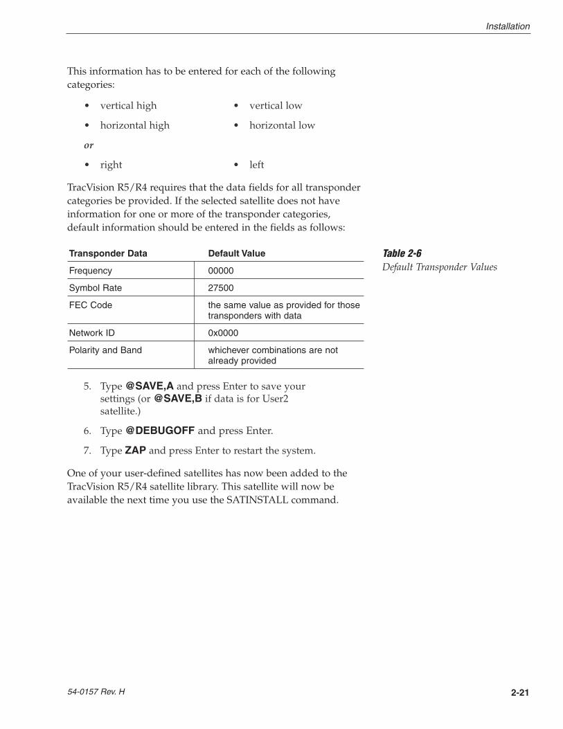
This information has to be entered for each of the followingcategories:
• vertical high • vertical low
• horizontal high • horizontal low
or
• right • left
TracVision R5/R4 requires that the data fields for all transpondercategories be provided. If the selected satellite does not haveinformation for one or more of the transponder categories,default information should be entered in the fields as follows:
Transponder Data Default Value
Frequency 00000
Symbol Rate 27500
FEC Code the same value as provided for thosetransponders with data
Network ID 0x0000
Polarity and Band whichever combinations are notalready provided
5. Type @SAVE,A and press Enter to save yoursettings (or @SAVE,B if data is for User2satellite.)
6. Type @DEBUGOFF and press Enter.
7. Type ZAP and press Enter to restart the system.
One of your user-defined satellites has now been added to theTracVision R5/R4 satellite library. This satellite will now beavailable the next time you use the SATINSTALL command.
2-21
Installation
54-0157 Rev. H
Table 2-6Default Transponder Values

An Example of Configuring a User-defined Satellite (Europe)
The following is an example of configuring the fictionalYOURSAT 101 as the USER1 configured satellite. Prior toconfiguring this satellite or any others, be certain to get the mostup-to-date information from one of the sources previouslydiscussed.
YOURSAT 101 at 71 West, DVB decoder, Circular Polarization LNB
Horizontal High
Frequency 11.966 GHz
Symbol Rate 27500
FEC Code 3/4
Network ID 2048 (dec) = 0x0800
Vertical High
Frequency 11.823 GHz
Symbol Rate 27500
FEC Code 3/4
Network ID 2048(dec) = 0x0800
Vertical Low
No Data Listed
Horizontal Low
No Data Listed
Based on this information, the data entered via the PC wouldlook like this, assuming that YOURSAT 101 would be Satellite A:
SATCONFIG,USER1,7,W,3,L
@DEBUGON
@SATCONFIG,A,98,11966,27500,34,0x0800,H,H,3
@SATCONFIG,A,98,11823,27500,34,0x0800,V,H,3
@SATCONFIG,A,98,00000,27500,34,0x0000,V,L,3
@SATCONFIG,A,98,00000,27500,34,0x0000,H,L,3
@SAVE,A
@DEBUGOFF
ZAP
2-22
A Guide to TracVision R5/R4
Table 2-7Sample User-defined
Satellite Configuration (Europe)
An Example of Configuring a User-defined Satellite (N. America)
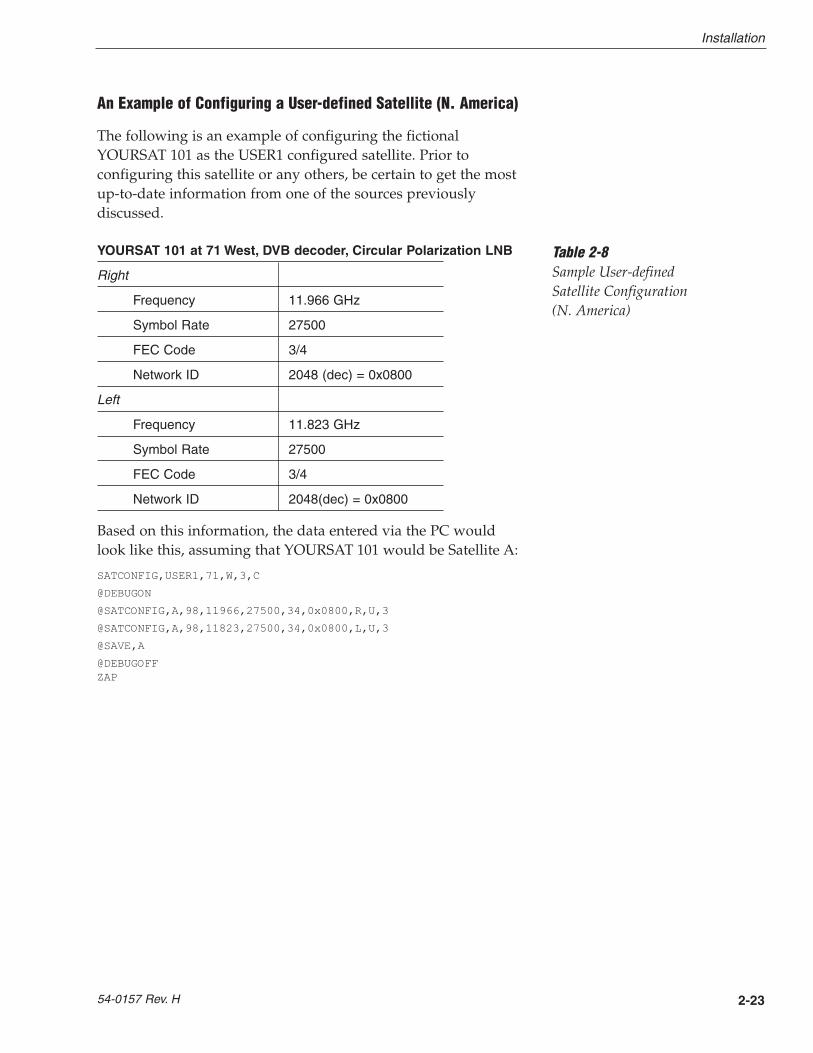
The following is an example of configuring the fictionalYOURSAT 101 as the USER1 configured satellite. Prior toconfiguring this satellite or any others, be certain to get the mostup-to-date information from one of the sources previouslydiscussed.
YOURSAT 101 at 71 West, DVB decoder, Circular Polarization LNB
Right
Frequency 11.966 GHz
Symbol Rate 27500
FEC Code 3/4
Network ID 2048 (dec) = 0x0800
Left
Frequency 11.823 GHz
Symbol Rate 27500
FEC Code 3/4
Network ID 2048(dec) = 0x0800
Based on this information, the data entered via the PC wouldlook like this, assuming that YOURSAT 101 would be Satellite A:
SATCONFIG,USER1,71,W,3,C
@DEBUGON
@SATCONFIG,A,98,11966,27500,34,0x0800,R,U,3
@SATCONFIG,A,98,11823,27500,34,0x0800,L,U,3
@SAVE,A
@DEBUGOFFZAP
2-23
Installation
54-0157 Rev. H
Table 2-8Sample User-defined Satellite Configuration (N. America)
2-24
A Guide to TracVision R5/R4
2.6 Setting the Skew Angle(European Systems Only)
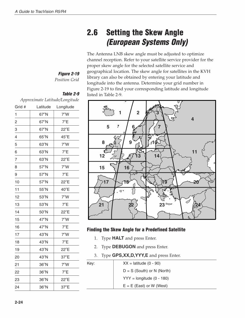
The Antenna LNB skew angle must be adjusted to optimizechannel reception. Refer to your satellite service provider for theproper skew angle for the selected satellite service andgeographical location. The skew angle for satellites in the KVHlibrary can also be obtained by entering your latitude andlongitude into the antenna. Determine your grid number inFigure 2-19 to find your corresponding latitude and longitudelisted in Table 2-9.
Finding the Skew Angle for a Predefined Satellite
1. Type HALT and press Enter.
2. Type DEBUGON and press Enter.
3. Type GPS,XX,D,YYY,E and press Enter.
Key: XX = latitude (0 - 90)
D = S (South) or N (North)
YYY = longitude (0 - 180)
E = E (East) or W (West)
1 2 34
11
765
8 9 10
12 13 14
16 15
17 18 19 20
21 22 23 24
Figure 2-19Position Grid
Grid # Latitude Longitude
1 67ºN 7ºW
2 67ºN 7ºE
3 67ºN 22ºE
4 65ºN 45ºE
5 63ºN 7ºW
6 63ºN 7ºE
7 63ºN 22ºE
8 57ºN 7ºW
9 57ºN 7ºE
10 57ºN 22ºE
11 55ºN 40ºE
12 53ºN 7ºW
13 53ºN 7ºE
14 50ºN 22ºE
15 47ºN 7ºW
16 47ºN 7ºE
17 43ºN 7ºW
18 43ºN 7ºE
19 43ºN 22ºE
20 43ºN 37ºE
21 36ºN 7ºW
22 36ºN 7ºE
23 36ºN 22ºE
24 36ºN 37ºE
Table 2-9Approximate Latitude/Longitude
2-25
Installation
54-0157 Rev. H
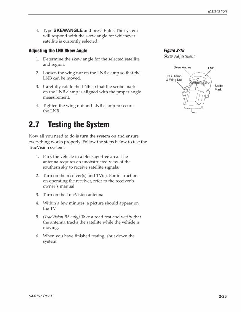
Skew Angles
LNB Clamp �& Wing Nut
ScribeMark
LNB
Figure 2-18Skew Adjustment
4. Type SKEWANGLE and press Enter. The systemwill respond with the skew angle for whicheversatellite is currently selected.
Adjusting the LNB Skew Angle
1. Determine the skew angle for the selected satelliteand region.
2. Loosen the wing nut on the LNB clamp so that theLNB can be moved.
3. Carefully rotate the LNB so that the scribe markon the LNB clamp is aligned with the proper anglemeasurement.
4. Tighten the wing nut and LNB clamp to secure the LNB.
2.7 Testing the SystemNow all you need to do is turn the system on and ensureeverything works properly. Follow the steps below to test theTracVision system.
1. Park the vehicle in a blockage-free area. Theantenna requires an unobstructed view of thesouthern sky to receive satellite signals.
2. Turn on the receiver(s) and TV(s). For instructionson operating the receiver, refer to the receiver’sowner’s manual.
3. Turn on the TracVision antenna.
4. Within a few minutes, a picture should appear onthe TV.
5. (TracVision R5 only) Take a road test and verify thatthe antenna tracks the satellite while the vehicle ismoving.
6. When you have finished testing, shut down thesystem.
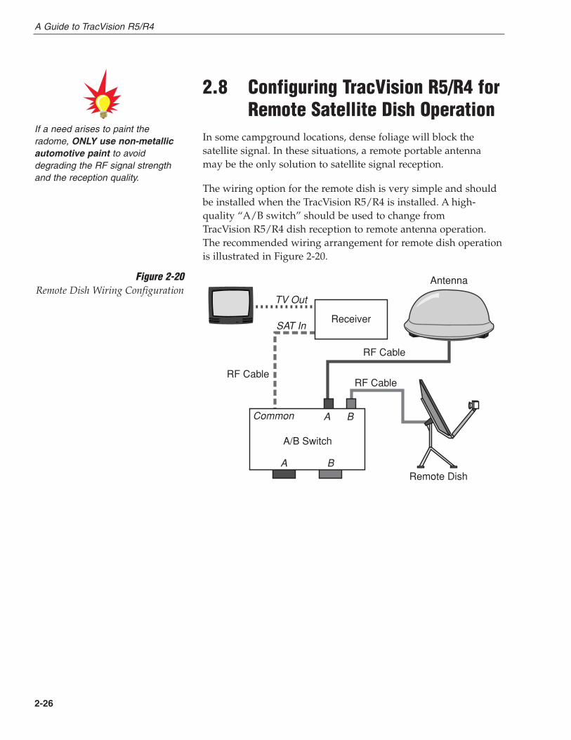
2.8 Configuring TracVision R5/R4 forRemote Satellite Dish Operation
In some campground locations, dense foliage will block thesatellite signal. In these situations, a remote portable antennamay be the only solution to satellite signal reception.
The wiring option for the remote dish is very simple and shouldbe installed when the TracVision R5/R4 is installed. A high-quality “A/B switch” should be used to change from TracVision R5/R4 dish reception to remote antenna operation.The recommended wiring arrangement for remote dish operationis illustrated in Figure 2-20.
2-26
A/B Switch
A B
A B
Common
TV Out
SAT In
Antenna
Remote Dish
RF Cable
RF CableRF Cable
Receiver
Figure 2-20Remote Dish Wiring Configuration
If a need arises to paint theradome, ONLY use non-metallicautomotive paint to avoiddegrading the RF signal strengthand the reception quality.
A Guide to TracVision R5/R4
2-27
Installation
54-0157 Rev. H
2.9 Changing Geographic LocationIf you move from Europe to the U.S., or from the U.S. to Europe,you will need to modify your TracVision R5/R4 system to receivesatellite TV signals in the new geographic area.
To begin receiving satellite signals in the new area, perform thefollowing steps.
Swap LNBs
To receive the proper satellite signals in the new geographiclocation, your TracVision antenna must be equipped with theappropriate LNB for that location. If moving from Europe to theU.S., you will need to install a North American-style LNB. Ifmoving from the U.S. to Europe, you will need to install aEuropean-style LNB. Table 2-10 lists the part numbers forordering these LNB options.
Part Name Part Number
European-style LNB 19-0196
North American-style LNB 19-0056
With the new part, you will receive an easy-to-understandinstruction sheet for swapping the LNBs.
Install New Satellites
When you move to a new area, the list of available satelliteschanges. If you’re moving to Europe, you will need to choose anew satellite pair from the list of available European satellites(see Table 2-4). If you’re moving to the U.S., you will need tochoose a new satellite pair from the list of available NorthAmerican satellites (see Table 2-3). For details on installing thesenew satellites, refer to Section 2.5.1, “Installing Your SelectedSatellites.”
Replace the Receiver
In order to receive satellite TV service in your new geographiclocation, you will need to purchase an receiver designed for thatlocation. Refer to your satellite TV service provider for moreinformation.
Table 2-10LNB Part Numbers
You may also need to replace yourtelevision when changinggeographic location. In NorthAmerica, your TV must support theNTSC video standard. In Europe,your TV must support the PALvideo standard.
3 Using Your TracVision R5/R4
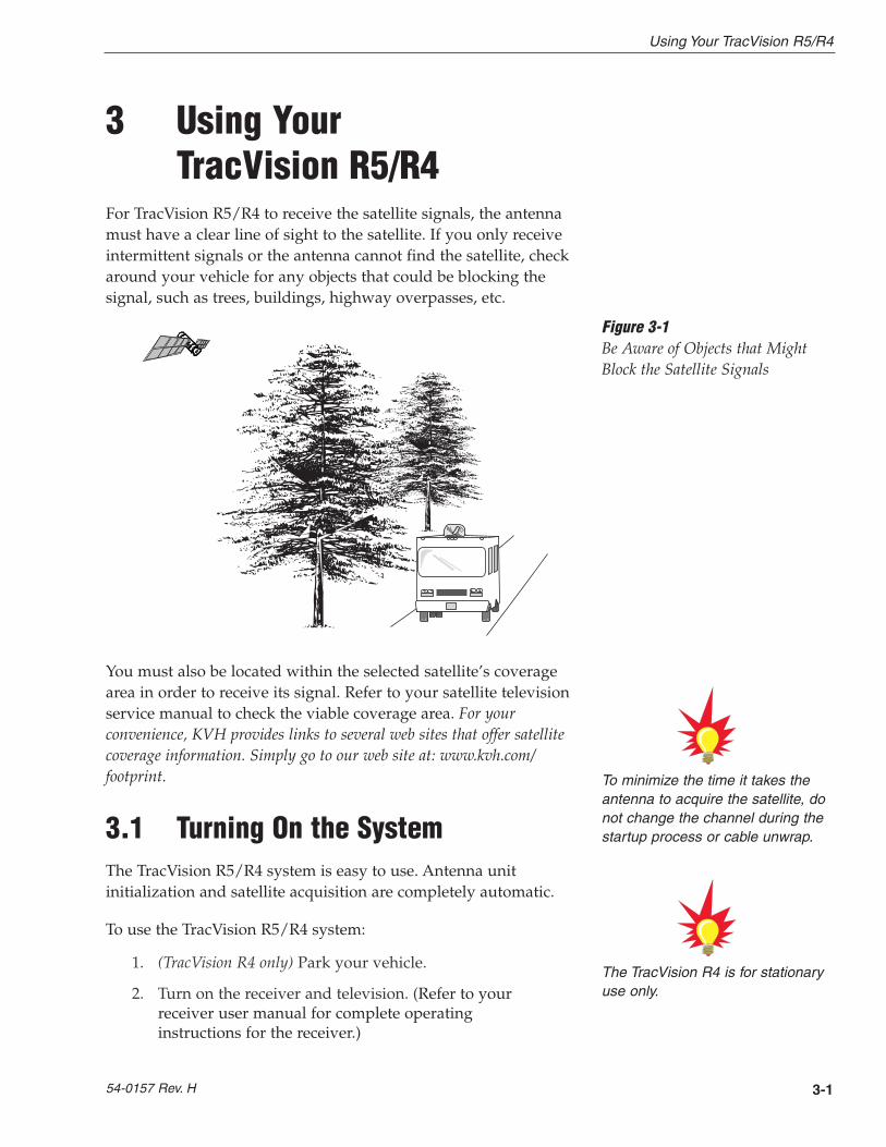
For TracVision R5/R4 to receive the satellite signals, the antennamust have a clear line of sight to the satellite. If you only receiveintermittent signals or the antenna cannot find the satellite, checkaround your vehicle for any objects that could be blocking thesignal, such as trees, buildings, highway overpasses, etc.
You must also be located within the selected satellite’s coveragearea in order to receive its signal. Refer to your satellite televisionservice manual to check the viable coverage area. For yourconvenience, KVH provides links to several web sites that offer satellitecoverage information. Simply go to our web site at: www.kvh.com/footprint.
3.1 Turning On the SystemThe TracVision R5/R4 system is easy to use. Antenna unitinitialization and satellite acquisition are completely automatic.
To use the TracVision R5/R4 system:
1. (TracVision R4 only) Park your vehicle.
2. Turn on the receiver and television. (Refer to yourreceiver user manual for complete operatinginstructions for the receiver.)
3-1
Using Your TracVision R5/R4
54-0157 Rev. H
To minimize the time it takes theantenna to acquire the satellite, donot change the channel during thestartup process or cable unwrap.
Figure 3-1Be Aware of Objects that MightBlock the Satellite Signals
The TracVision R4 is for stationaryuse only.
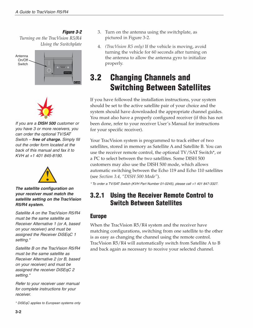
3. Turn on the antenna using the switchplate, aspictured in Figure 3-2.
4. (TracVision R5 only) If the vehicle is moving, avoidturning the vehicle for 60 seconds after turning onthe antenna to allow the antenna gyro to initializeproperly.
3.2 Changing Channels andSwitching Between Satellites
If you have followed the installation instructions, your systemshould be set to the active satellite pair of your choice and thesystem should have downloaded the appropriate channel guides.You must also have a properly configured receiver (if this has notbeen done, refer to your receiver User’s Manual for instructionsfor your specific receiver).
Your TracVision system is programmed to track either of twosatellites, stored in memory as Satellite A and Satellite B. You canuse the receiver remote control, the optional TV/SAT Switch*, ora PC to select between the two satellites. Some DISH 500customers may also use the DISH 500 mode, which allowsautomatic switching between the Echo 119 and Echo 110 satellites(see Section 3.4, “DISH 500 Mode”).
* To order a TV/SAT Switch (KVH Part Number 01-0245), please call +1 401 847-3327.
3.2.1 Using the Receiver Remote Control toSwitch Between Satellites
EuropeWhen the TracVision R5/R4 system and the receiver havematching configurations, switching from one satellite to the otheris as easy as changing the channel using the remote control.TracVision R5/R4 will automatically switch from Satellite A to Band back again as necessary to receive your selected channel.
3-2
A Guide to TracVision R5/R4
The satellite configuration onyour receiver must match thesatellite setting on the TracVisionR5/R4 system.
Satellite A on the TracVision R5/R4must be the same satellite asReceiver Alternative 1 (or A, basedon your receiver) and must beassigned the Receiver DiSEqC 1setting.*
Satellite B on the TracVision R5/R4must be the same satellite asReceiver Alternative 2 (or B, basedon your receiver) and must beassigned the receiver DiSEqC 2setting.*
Refer to your receiver user manualfor complete instructions for yourreceiver.
* DiSEqC applies to European systems only
Antenna�On/Off�Switch
Figure 3-2Turning on the TracVision R5/R4
Using the Switchplate
If you are a DISH 500 customer oryou have 3 or more receivers, youcan order the optional TV/SATSwitch – free of charge. Simply fillout the order form located at theback of this manual and fax it toKVH at +1 401 845-8190.
North America
DIRECTV Subscribers
DIRECTV subscribers in certain regions of the United States willrequire a DSS Plus receiver to receive broadcasts from multiplesatellites. If connected to the antenna’s RF1 connector, the DSSPlus receiver allows you to switch channels using the remotecontrol. If you are a DIRECTV subscriber, but do not have a DSSPlus receiver, or you are using a multiswitch, use the optionalTV/SAT Switch or a PC, as described in the following sections.
DISH Network Subscribers
Most DISH Network customers will need to manually changesatellites using the optional TV/SAT Switch or a PC, as describedin the following sections.
DISH Network customers with DISH 500 service and a DishPro 301receiver may also use DISH 500 mode. DISH 500 mode automaticallyswitches between the Echo 119 and Echo 110 satellites when the channelis changed using the receiver’s remote control. To configure yourTracVision R5/R4 for this feature, go to Section 3.4, “DISH 500Mode.”
ExpressVu Subscribers
ExpressVu customers can use the optional TV/SAT Switch or aPC, as described in the following sections.
3.2.2 Using the TV/SAT Switch to SwitchBetween Satellites - Optional
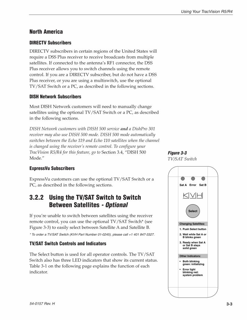
If you’re unable to switch between satellites using the receiverremote control, you can use the optional TV/SAT Switch* (seeFigure 3-3) to easily select between Satellite A and Satellite B.
* To order a TV/SAT Switch (KVH Part Number 01-0245), please call +1 401 847-3327.
TV/SAT Switch Controls and Indicators
The Select button is used for all operator controls. The TV/SATSwitch also has three LED indicators that show its current status.Table 3-1 on the following page explains the function of eachindicator.
3-3
Using Your TracVision R5/R4
54-0157 Rev. H
Sat A Error
Other Indicators:
• Both blinking green: initializing
• Error light blinking red: system problem
Changing Satellites:
1.Push Select button
2.Wait while Sat A or B blinks green
3.Ready when Sat A or Sat B stays solid green
Sat B
Select
Figure 3-3TV/SAT Switch

Indicator Status Meaning
Sat A Blinking green Wait – Searching for satellite
Solid green Tracking Satellite A
Error Blinking red System problem – Refer to Section 4, “Troubleshooting,”to find the possible cause
Sat B Blinking green Wait – Searching for satellite
Solid green Tracking Satellite B
Connecting the TV/SAT Switch
To use the TV/SAT Switch, you must first connect it to theTracVision system.
1. Connect the TV/SAT Switch’s data cable to themaintenance port on the switchplate (see Figure 3-4).
2. The Sat A and Sat B indicators blink while thesystem initializes.
3. Either the Sat A or Sat B indicator will turn solidgreen, denoting which satellite is currently beingtracked.
Using the TV/SAT Switch
The TV/SAT Switch is very easy to use. All operations arecontrolled through a single button.
To select the second satellite, perform the following steps:
1. Press the Select button on the TV/SAT Switch.
2. The indicator for the current satellite (Sat A or Sat B) extinguishes, while the indicator for theother satellite starts blinking.
3. Once the indicator for the other satellite turnssolid green, the TracVision system is tracking thenewly selected satellite. You can now use yourreceiver to choose a channel on the new satellite.
3-4
A Guide to TracVision R5/R4
Maintenance Port �(DB9 Connector)
Figure 3-4Switchplate Maintenance Port
Table 3-1TV/SAT Switch LED Indicators
3.2.3 Using a PC to Switch Between Satellites
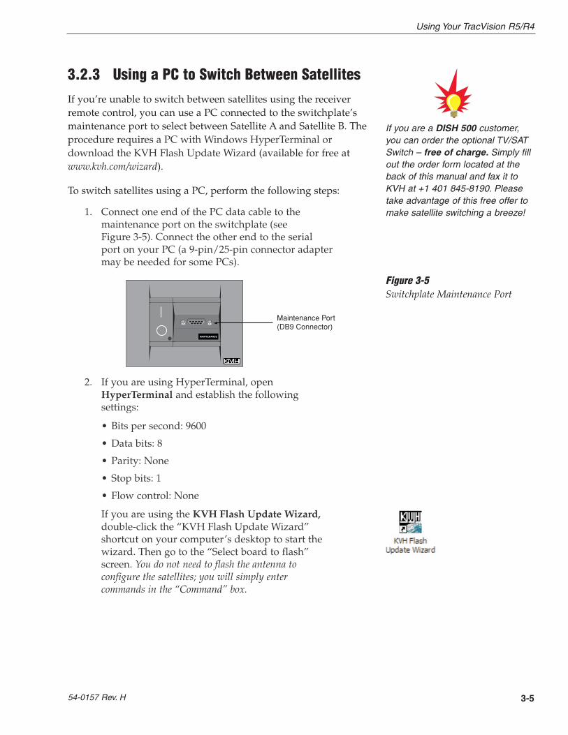
If you’re unable to switch between satellites using the receiverremote control, you can use a PC connected to the switchplate’smaintenance port to select between Satellite A and Satellite B. Theprocedure requires a PC with Windows HyperTerminal ordownload the KVH Flash Update Wizard (available for free atwww.kvh.com/wizard).
To switch satellites using a PC, perform the following steps:
1. Connect one end of the PC data cable to themaintenance port on the switchplate (see Figure 3-5). Connect the other end to the serialport on your PC (a 9-pin/25-pin connector adaptermay be needed for some PCs).
2. If you are using HyperTerminal, openHyperTerminal and establish the followingsettings:
• Bits per second: 9600
• Data bits: 8
• Parity: None
• Stop bits: 1
• Flow control: None
If you are using the KVH Flash Update Wizard,double-click the “KVH Flash Update Wizard”shortcut on your computer’s desktop to start thewizard. Then go to the “Select board to flash”screen. You do not need to flash the antenna toconfigure the satellites; you will simply entercommands in the “Command” box.
3-5
Using Your TracVision R5/R4
54-0157 Rev. H
Maintenance Port �(DB9 Connector)
Figure 3-5Switchplate Maintenance Port
If you are a DISH 500 customer,you can order the optional TV/SATSwitch – free of charge. Simply fillout the order form located at theback of this manual and fax it toKVH at +1 401 845-8190. Pleasetake advantage of this free offer tomake satellite switching a breeze!

3. Type @L,X and press Enter once the dataconnection is made.
Key: X = A or B (whichever satellite you want to track)
To select Satellite A, type @L,A and press Enter.
To select Satellite B, type @L,B and press Enter.
4. The antenna unit shifts to track the secondsatellite.
3.3 Watching TelevisionTracVision R5 is designed to operate whether your vehicle is inmotion or parked. TracVision R4 is designed to operate onlywhile your vehicle is parked.
Using Your TracVision R5/R4 When Parked
When your vehicle is stopped, it is not necessary for theTracVision R5/R4 to be turned on. After parking your vehicleand confirming that the antenna is receiving the satellite signal,you may turn off the TracVision R5/R4 unit to avoid unnecessaryuse of power. Because the LNB receives its power from thereceiver, the antenna will continue to receive the satellite TVsignals and relay them to the receiver.
However, if you plan to change to a channel that is broadcast byanother satellite, TracVision R5/R4 must be turned on so theantenna can search for, identify, and lock onto the differentsatellite.
Cable Unwrap
The antenna unit can rotate a full 720° before coming to the endof its cable. If it does so, the system automatically unwraps thecable by quickly rotating the dish in the opposite direction.During this process, your television transmission will be frozenmomentarily while the cable unwraps and the antenna reacquires the satellite.
3-6
A Guide to TracVision R5/R4
(TracVision R5 only) Don’t forget toturn the system back on before youstart driving again. The antennamust be turned on to track thesatellite while you are moving.

Sleep Mode (TracVision R5 only)
When the vehicle has come to a stop and the antenna holds itsposition for 1 minute, the antenna unit enters Sleep Mode, whichturns off the conical scan tracking, reducing any motor noise theantenna may be making. As soon as the vehicle moves, SleepMode will automatically be turned off and the system will begintracking the satellite again. This convenient feature is ideal forwhen a vehicle is parked for a short time or idling andpassengers want to watch TV.
KVH recognizes that some customers may not want to takeadvantage of this convenient feature. In this case, it is possible todisable Sleep Mode using a simple software command as follows:
1. Connect a laptop computer to the system using themaintenance port and use the KVH Flash UpdateWizard or HyperTerminal, as described in Section2.5.1, “Installing Your Selected Satellites.”
2. Turn on the antenna. When the limit switch test iscomplete:
a. Type HALT and press Enter.
b. Type DEBUGON and press Enter.
c. Type SLEEPOFF and press Enter.
3. Turn the antenna off by pressing its power button.
4. Wait 30 seconds and press the antenna’s powerbutton to turn the antenna back on. Sleep Mode isnow disabled. To reactivate Sleep Mode, follow thissame process, typing SLEEPON instead ofSLEEPOFF during Step c.
Conical Scan Tracking (TracVision R5 only)
The antenna control unit uses conical scanning to maintain peaksignal strength to the receiver and to update the satellite’sposition. When conical scan tracking is active, the antenna movescontinually with a circular motion to sweep across the satellite’speak signal. The signal strength is then fed back to the controlcircuits to keep coming back to the direction of the strongestsignal.
3-7
Using Your TracVision R5/R4
54-0157 Rev. H
Unlike turning the power off, theantenna will still be operational anddrawing power when in SleepMode. If you are going to be parkedfor an extended period of time,turning off the antenna willconserve power while still allowingyou to receive the TV signals.

If the satellite signal is lost while the system is in conical scantrack mode, the control software imposes a 45-second time-outdelay. If the signal is not regained during that time, the antennareverts to the set of Search Modes to start looking for the satellitesignal. This is an automatic process that does not require userintervention.
3.4 DISH 500 ModeDISH Network customers with DISH 500 service and a DishPro301 receiver may configure the TracVision R5/R4 system to useDISH 500 mode. DISH 500 mode automatically switches betweenthe Echo 119 and Echo 110 satellites when the channel is changedusing the receiver’s remote control.
Configuring the Antenna for DISH 500 Mode
To configure the TracVision antenna for DISH 500 mode, you willneed to run the receiver’s Check Switch function twice. You donot need a laptop computer.
To configure the TracVision antenna for DISH 500 mode, followthe steps below.
1. Park your vehicle in a blockage-free area and donot move the vehicle until you have completed theentire configuration process.
2. Turn on the master receiver (the receiver that isconnected to the antenna’s RF1 connector) and thetelevision.
3. Turn on the TracVision antenna using theswitchplate’s power switch.
4. Wait one minute for the antenna to initialize.
5. Using the receiver’s remote control, go to the“Point Dish/Signal Strength” screen (press Menu,6, 1, 1 (on most models)).
6. Using the remote control’s arrow buttons,highlight “Check Switch” and press the Selectbutton.
7. Highlight “Test” and press Select.
3-8
A Guide to TracVision R5/R4
N E T W O R K

8. Wait a minimum of 15 minutes for the CheckSwitch function to complete and for the antenna torestart and configure itself for DISH 500 mode.
If the Check Switch function fails (the receiver locksup), disconnect power from the receiver, restart theantenna, then restore power to the receiver and try theCheck Switch function again.
9. Run the Check Switch function a second time. Thisallows the receiver to configure itself for automaticsatellite switching.
10. Wait until the Check Switch function is complete(it will take a couple minutes).
11. Ensure that the following is displayed on the TV:
This indicates that the receiver is configuredproperly. If this information is not displayedexactly as shown above, try running the CheckSwitch function again.
12. Exit the menu and allow the receiver to downloadthe program guide.
13. Once the program guide has loaded, you can startenjoying satellite TV. The antenna will now switchbetween satellites automatically as you changechannels using the receiver’s remote control.
3-9
Using Your TracVision R5/R4
54-0157 Rev. H
Installed Switch: SW42
Input: 1 1 2 2
Satellite: 119 119 110 110
Polarity: Odd Even Odd Even
Status: Satellite reception verified
Figure 3-6Check Switch Screen
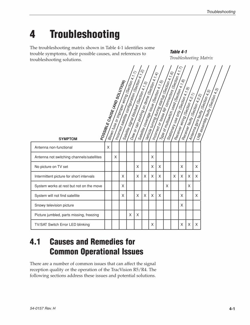
4 TroubleshootingThe troubleshooting matrix shown in Table 4-1 identifies sometrouble symptoms, their possible causes, and references totroubleshooting solutions.
4.1 Causes and Remedies forCommon Operational Issues
There are a number of common issues that can affect the signalreception quality or the operation of the TracVision R5/R4. Thefollowing sections address these issues and potential solutions.
4-1
Troubleshooting
54-0157 Rev. H
Table 4-1Troubleshooting Matrix
Antenna non-functional X
Antenna not switching channels/satellites X X
No picture on TV set X X X X X
Intermittent picture for short intervals X X X X X X X X X
System works at rest but not on the move X X X
System will not find satellite X X X X X X X
Snowy television picture X
Picture jumbled, parts missing, freezing X X
TV/SAT Switch Error LED blinking X X X X
Sat
ellit
eco
vera
geis
sue
(Sec
tion
4.1.
5)
Rec
eive
r wiri
ng(S
ectio
n4.
2.1)
Ant
enna
gyro
faul
ty(S
ectio
n4.
3)
LNB
asse
mbl
yfa
ulty
(Sec
tion
4.3)
Rec
eive
r fau
lty(S
ectio
n4.
2.2)
Sat
ellit
esi
gnal
bloc
ked
(Sec
tion
4.1.
3)
Inco
rrec
t or l
oose
RF
conn
ecto
rs(S
ectio
n4.
1.7)
PO
SS
IBLE
CA
US
E(A
ND
SO
LUTI
ON
)
SYMPTOM Vehi
cle
turn
ing
durin
gst
artu
p(S
ectio
n4.
1.6)
Dew
orra
inpo
olin
gon
dom
e(S
ectio
n4.
1.4)
Blo
wn
fuse
orim
prop
erw
iring
(Sec
tion
4.1.
1)
Inco
rrec
t sat
ellit
eco
nfig
urat
ion
(Sec
tion
4.1.
2)
Type
ofm
ultis
witc
hus
ed(S
ectio
n4.
1.8)
Sta
tiona
ryus
eon
ly(S
ectio
n4.
1.9)
4.1.1 Blown Fuse or Improper Wiring
If the antenna unit is installed but entirely non-responsive, thereare three key factors to check as part of the troubleshootingprocess:
1. Blown Fuse – The antenna unit is equipped withtwo fuses mounted on its CPU Board. If either ofthese fuses has blown or been broken, the antennaunit will not operate. Refer to Section 5.4.1, “PCBRemoval and Replacement,” for details on the fuselocations and how to access the CPU Board.
2. Wiring – If the system has been improperly wired,the antenna unit will not operate correctly. Refer toSection 2.3, “Connecting System Components,” forcomplete system wiring information.
4.1.2 Incorrect Satellite Configuration
The satellite configuration on your receiver must match thesatellite setting on the TracVision R5/R4 system.
• Satellite A on the TracVision R5/R4 must be thesame satellite as Receiver Alternative 1 (or A,based on your receiver) and must be assigned theReceiver DiSEqC 1 setting.*
• Satellite B on the TracVision R5/R4 must be thesame satellite as Receiver Alternative 2 (or B,based on your receiver) and must be assigned theReceiver DiSEqC 2 setting.*
* The DiSEqC settings only apply to European systems.
Refer to your receiver user manual for complete instructions onconfiguring your receiver.
4.1.3 Satellite Signal Blocked
Satellite signals can be blocked or degraded by trees andbranches, buildings, mountains, overpasses, or equipment on thevehicle itself. Refer to Section 2.1, “Choosing the Best Location,” tomake certain that the TracVision R5/R4 unit is in the optimallocation. Simply moving the vehicle to clear an externalobstruction will also restore signal quality.
4-2
A Guide to TracVision R5/R4
4.1.4 Dew or Rain Pooling on Dome
Dew or rain can occasionally pool on the top of the radome.While this moisture will usually be dispersed when the vehicle isin motion, it can disrupt the signal while the vehicle is at rest.This issue can be minimized with two approaches:
1. Spray the dome with hosed water to remove thedew from the dome surface.
2. Periodically apply liquid dish detergent to thedome surface. Wipe the full-strength detergent onthe dome and allow it to dry. This treatment willprovide a film that will help moisture roll off thedome.
4.1.5 Satellite Coverage Issue
TracVision R5/R4 will provide outstanding reception throughoutthe entire coverage area for your satellite television service ofchoice. However, signal quality can be degraded as you approachthe fringe coverage areas. Refer to your satellite television servicemanual to check the viable coverage area.
4.1.6 Vehicle Turning During Startup(TracVision R5 only)
If the vehicle turns during the 60-second startup andinitialization sequence that occurs immediately after turningon the power to the TracVision R5 unit, the antenna gyro willrecord that variable motion as “standing still.” This may causethe antenna to track improperly. To solve this problem, turnTracVision R5 off for at least 10 seconds. Turn the system backon, making certain that the vehicle is either motionless ortraveling in a straight line for the 60 seconds immediatelyfollowing power-up.
4-3
Troubleshooting
54-0157 Rev. H
For your convenience, KVHprovides links to several web sitesthat offer satellite coverageinformation. Simply go to our website at www.kvh.com/footprint.

4.1.7 Incorrect or Loose RF Connectors
As part of preventive maintenance (described in Section 5,“Maintenance”) KVH recommends checking the antenna unitcable connections. A loose RF connector can reduce signal quality.In addition, if you are unable to switch to the other programmedsatellite, make sure that you have connected your RF signal cableto the antenna baseplate connector labeled “RF1” (see Section 2.3.5, “Connecting the Antenna RF Signal Cable to theReceiver”).
4.1.8 Type of Multiswitch Used(North American Systems Only)
An active multiswitch must always be used to connect theTracVision R5/R4 system to multiple receivers. Refer to Section 2.3.5, “Connecting the Antenna RF Signal Cable to theReceiver,” for directions on proper multiswitch/multiple receiver cabling.
4.1.9 Stationary Use Only (TracVision R4 only)
The TracVision R4 antenna was designed for stationary use only.As such, the antenna will track the desired satellite while yourvehicle is parked, but not while the vehicle is in motion.
4.2 Receiver TroubleshootingThe receiver that was provided with your satellite televisionservice may also be the cause of less-than-ideal operation.
4.2.1 Receiver Wiring
Refer to Section 2.3.5, “Connecting the Antenna RF Signal Cable tothe Receiver,” and your receiver user manual to confirm that thereceiver is properly connected to the antenna unit and thetelevision.
4.2.2 Receiver Faulty
In the case of a faulty receiver, refer to your receiver user manualfor service, replacement, and warranty information.
4-4
A Guide to TracVision R5/R4
KVH offers an upgrade kit (KVHPart #02-1026) that adds in-motiontracking capability to the TracVision R4, allowing you toreceive satellite signals while onthe move.

4.3 Antenna Gyro and LNB FaultsSection 5, “Maintenance,” provides detailed instructions forauthorized service personnel who may be required to replaceTracVision R5/R4 components. The TracVision R4 does not includean antenna gyro.
4.4 Computer DiagnosticsTracVision R5/R4 has been designed to provide diagnosticreadouts on a PC with a RS-232 serial communication port. If youare unable to isolate a system problem with the foregoingtroubleshooting tools, set up a laptop to carry out computerdiagnostics as described below. System problems should befound somewhere through the diagnostic readouts.
The procedure requires a PC with Windows HyperTerminal ordownload the KVH Flash Update Wizard (available for free atwww.kvh.com/wizard).
1. Connect one end of the PC data cable to themaintenance port on the switchplate (see Figure 3-5). Connect the other end to the serialport on your PC (a 9-pin/25-pin connector adaptermay be needed for some PCs).
2. If you are using HyperTerminal, open it andestablish the following settings:
• Bits per second: 9600
• Data bits: 8
• Parity: None
• Stop bits: 1
• Flow control: None
If you are using the KVH Flash Update Wizard,double-click the “KVH Flash Update Wizard”shortcut on your computer’s desktop to start thewizard. Then go to the “Select board to flash”screen. You do not need to flash the antenna toconfigure the satellites; you will simply entercommands in the “Command” box.
4-5
Troubleshooting
54-0157 Rev. H

3. Apply power to the TracVision R5/R4 system andallow the system to complete full initialization.Data should be scrolling on the PC display toidentify any system problems detected. If no datais seen, recheck your connections and the terminalsoftware setup.
4-6
A Guide to TracVision R5/R4

5-1
Maintenance
54-0157 Rev. H
5 Maintenance
5.1 Warranty/Service InformationFor information on KVH warranty, repair, and liability policies,please refer to the complete warranty statement provided withyour KVH product. If you have any questions, please call yourlocal authorized dealer/installer or distributor, or contact KVH orKVH Europe directly.
5.2 Preventive MaintenanceTracVision R5/R4 requires minimal preventive maintenance. Thefollowing tasks are sufficient to maintain peak performance.
Monthly
• Wash the exterior of the radome and baseplateassembly with fresh water; a mild detergent maybe added to remove grime. Do not spray theradome directly with high-pressure water.
• Do not apply abrasive cleaners or volatile solventssuch as acetone to the ABS radome.
Annually
• Remove the radome and examine the interior ofthe antenna unit for signs of corrosion, looseconnections, or frayed or broken wires.
• Visually inspect the elevation drive shaft to becertain that it moves easily and is clear of grit anddebris.
When cleaning the radome, avoidany compounds that react withplastic.
5-2
A Guide to TracVision R5/R4
5.3 Replaceable PartsTracVision R5/R4 has been designed with durability and lowmaintenance in mind. If you experience an operating problem orotherwise require technical assistance, contact your localauthorized TracVision R5/R4 dealer/distributor first. Have theantenna unit serial number ready with a list of the troublesymptoms. If an authorized dealer/distributor is not locatednearby, contact the factory directly at the telephone, facsimile, ore-mail listings inside the front cover.
Replacement part numbers for units that can be serviced in thefield are listed in Table 5-1. These parts may be obtained fromany KVH authorized dealer/distributor.
Part Name Part Number
Baseplate Assembly (TracVision R5) 02-1245-01*02-1245-03**
Baseplate Assembly (TracVision R4) 02-1245-02*02-1245-04**
Radome Assembly (TracVision R5) 02-0953-03†
Radome Assembly (TracVision R4) 02-0953-05†
Data/Power Cable 32-0730-28
RF Cable 32-0417-28
PC Cable 32-0628-06
CPU PCB 02-1043-02
RF PCB 02-1342
Antenna Gyro (TracVision R5 only) 02-1035
Antenna Gyro Gasket (TracVision R5 only) 24-0139
System Fuses 16-0017-3150
LNB (European System) 19-0346
LNB (N. American System) 19-0056
Switchplate 02-1023-01
TV/SAT Switch (optional) 01-0245
* Baseplate assembly with single-output LNB** Baseplate assembly with dual-output LNB† Specify color when ordering
It is recommended that all other technical difficulties be resolvedby returning the TracVision R5/R4 unit to an authorized serviceprovider.
Table 5-1Field Replaceable Units
Should a fuse ever need to bereplaced, TracVision R5/R4 usestwo 5x20 mm, 3.15-amp, 250-voltfast-blow fuses.
To help us continually improve thequality and reliability of oursystems, please return any failedcomponent to KVH or KVH Europe(care of the mailing address listedat the front of this manual) after youreceive your replacement part.
The serial number of yourTracVision R5/R4 will be requiredduring any troubleshooting orservice calls. You will find the serial number at the front of thismanual.

5-3
Maintenance
54-0157 Rev. H
5.4 Field Replaceable UnitProcedures
The following subsections provide detailed procedures forrepairing or swapping out field replaceable units. The proceduresrefer to labeled items presented on the following diagrams.
PCB
PCB Cover
Pan Head Screws
Rotating Plate
RF Board
Standoffs
RF Board Cover
RF Cover�Screws
Figure 5-2Close-up of Connecting Rod and E-ring
Always lift the antenna unit bythe gray baseplate, never by theradome or any portion of theantenna assembly!
Figure 5-1Antenna, PCB, and Rotating Plate
Antenna Gyro�(TracVision R5 only)
E-ring
Elevation Axis Motor Shaft
Linear Actuator
Connecting Rod
The antenna reflector is not shownin several figures for claritypurposes only. Do not remove theantenna reflector!
Before servicing the antenna unit,be sure to remove the appropriatevehicle fuse to disconnect power.Replace the fuse after completingthe service.
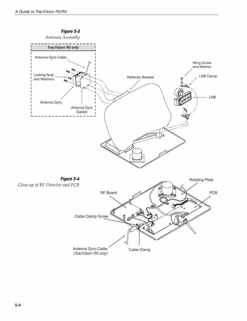
5-4
A Guide to TracVision R5/R4
Figure 5-3Antenna Assembly
Locking Nuts�and Washers
Antenna Gyro
Antenna Gyro Cable
Reflector Bracket
Wing Screw�and Washer
LNB Clamp
LNB
Antenna Gyro Gasket
TracVision R5 only
PCB
Cable Clamp
RF Board
Cable Clamp Screw
Rotating Plate
Antenna Gyro Cable (TracVision R5 only)
Figure 5-4Close-up of RF Detector and PCB

5-5
Maintenance
54-0157 Rev. H
5.4.1 PCB Removal and Replacement
Estimated Time to Repair: 1⁄2 hour
The microprocessor PCB assembly is protected by a coverfastened to the rotating plate – Fig. 5-1. The cover must beremoved to gain access to the main power fuses and the PCBassembly.
1. Using needle-nose pliers, remove the E-ring fromone end of the connecting rod – Fig. 5-2.
2. Remove the connecting rod by sliding it off thebracket.
3. Fully retract the elevation axis motor shaft – Fig. 5-5.
4. Remove 6 pan head screws from the PCB coverflanges.
5. Remove the PCB cover. To get the necessaryclearance, rotate the linear actuator up 90º whilelifting the PCB cover – Fig. 5-5.
6. Remove all cable connectors from the PCB. Figure 5-6 on the following page illustrates thePCB arrangement and connector locations.
TracVision R5/R4 is equipped withtwo 5x20 mm, 3.15-amp, 250-voltfast-blow fuses, which are mountedon the PCB. To access and replaceone of the fuses, remove the PCBcover.
When carrying out maintenance on the PCB, be sure to not dropany of the small screws inside themechanism. If a screw is lost withinthe baseplate, it must be retrievedto avoid causing any damage whenthe unit rotates.
PCB Cover
Linear Actuator
Elevation AxisMotor Shaft
Figure 5-5Removing the PCB Cover

5-6
A Guide to TracVision R5/R4
7. The PCB is mounted to the rotating plate with 9 pan head screws. Remove the screws and PCB.
8. Reverse this process to install the replacementPCB. Reinstall all cable connectors removed inStep 6.
9. (TracVision R5 only) Carry out all calibrationprocedures for the antenna gyro (Section 5.4.3).
10. Reinstall your preferred satellites as detailed inSection 2.5.1, “Installing Your Selected Satellites.”
5.4.2 RF Detector/DVB Decoder
Estimated Time to Repair: 1⁄2 hour
The RF Detector PCB receives operating voltages from both theCPU board and the receiver (via the RF cable). Ensure that allpower is turned off before proceeding.
1. Remove the 4 RF board cover screws and washersfrom the RF board cover.
2. Remove the RF board cover.
3. Remove the 2 RF connectors from the coaxialfittings on the RF board. Tag the cables to ensurethat they are returned to the same connectors.
4. Remove the 2 Molex connectors from the RF board(J3 and J1) – Fig. 5-6.
When replacing the PCB cover, becareful not to pinch any cables.
RF Board
PCB
J3 J1
RF Connector to IRD
RF Connector to LNB
Fuses
J5
J11
J9J2 J1
J4
Gyro (TracVision R5 only)
RF Board
Limit Switches
Power/Data
Elevation Motor Azimuth Motor
Figure 5-6PCB and RF Detector Board
Connector Locations
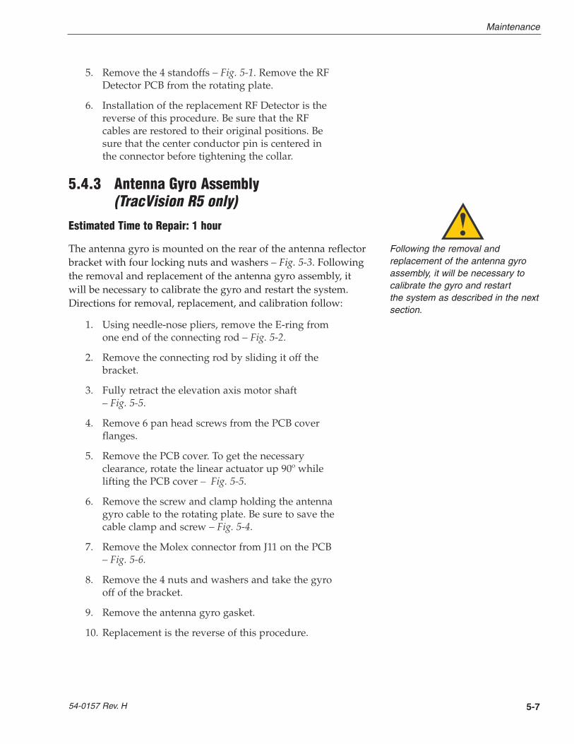
5-7
Maintenance
54-0157 Rev. H
5. Remove the 4 standoffs – Fig. 5-1. Remove the RFDetector PCB from the rotating plate.
6. Installation of the replacement RF Detector is thereverse of this procedure. Be sure that the RFcables are restored to their original positions. Besure that the center conductor pin is centered inthe connector before tightening the collar.
5.4.3 Antenna Gyro Assembly (TracVision R5 only)
Estimated Time to Repair: 1 hour
The antenna gyro is mounted on the rear of the antenna reflectorbracket with four locking nuts and washers – Fig. 5-3. Followingthe removal and replacement of the antenna gyro assembly, itwill be necessary to calibrate the gyro and restart the system.Directions for removal, replacement, and calibration follow:
1. Using needle-nose pliers, remove the E-ring fromone end of the connecting rod – Fig. 5-2.
2. Remove the connecting rod by sliding it off thebracket.
3. Fully retract the elevation axis motor shaft – Fig. 5-5.
4. Remove 6 pan head screws from the PCB coverflanges.
5. Remove the PCB cover. To get the necessaryclearance, rotate the linear actuator up 90º whilelifting the PCB cover – Fig. 5-5.
6. Remove the screw and clamp holding the antennagyro cable to the rotating plate. Be sure to save thecable clamp and screw – Fig. 5-4.
7. Remove the Molex connector from J11 on the PCB– Fig. 5-6.
8. Remove the 4 nuts and washers and take the gyrooff of the bracket.
9. Remove the antenna gyro gasket.
10. Replacement is the reverse of this procedure.
Following the removal andreplacement of the antenna gyroassembly, it will be necessary tocalibrate the gyro and restart the system as described in the nextsection.
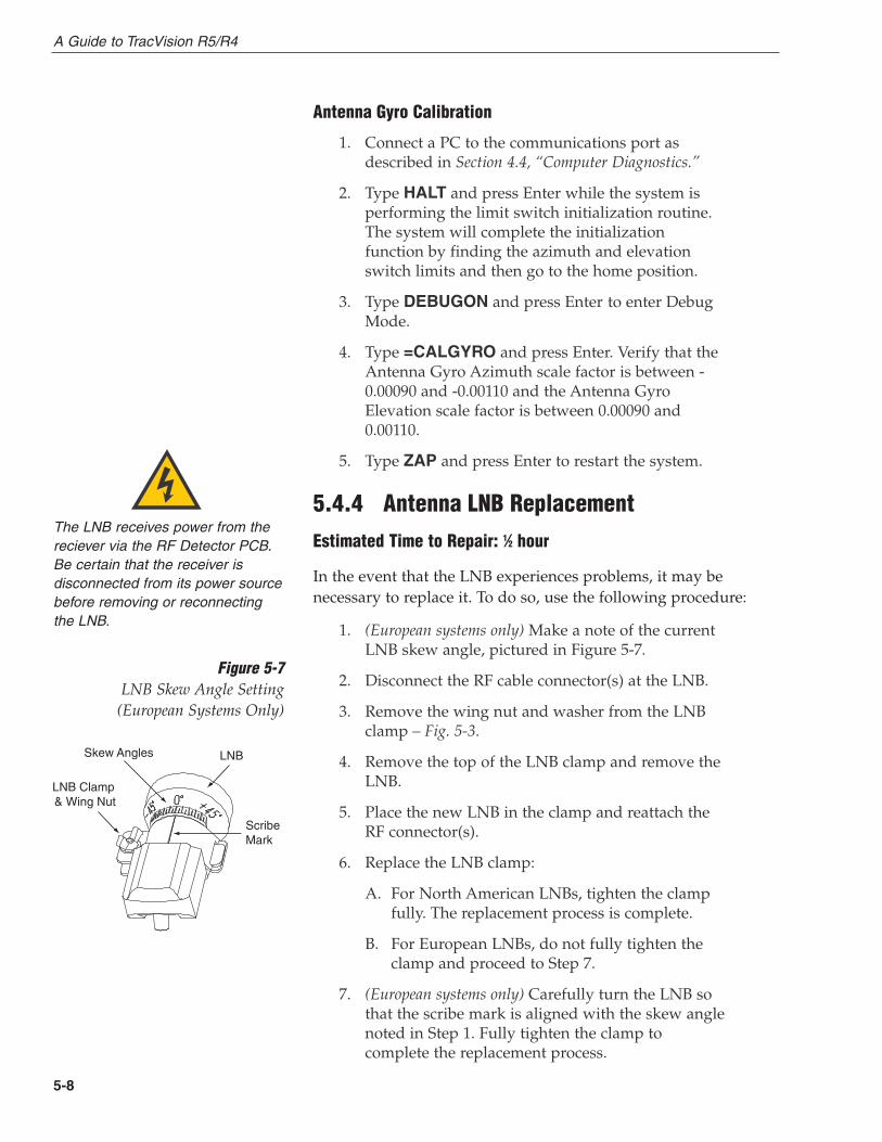
5-8
A Guide to TracVision R5/R4
Antenna Gyro Calibration
1. Connect a PC to the communications port asdescribed in Section 4.4, “Computer Diagnostics.”
2. Type HALT and press Enter while the system isperforming the limit switch initialization routine.The system will complete the initializationfunction by finding the azimuth and elevationswitch limits and then go to the home position.
3. Type DEBUGON and press Enter to enter DebugMode.
4. Type =CALGYRO and press Enter. Verify that theAntenna Gyro Azimuth scale factor is between -0.00090 and -0.00110 and the Antenna GyroElevation scale factor is between 0.00090 and0.00110.
5. Type ZAP and press Enter to restart the system.
5.4.4 Antenna LNB Replacement
Estimated Time to Repair: 1⁄2 hour
In the event that the LNB experiences problems, it may benecessary to replace it. To do so, use the following procedure:
1. (European systems only) Make a note of the currentLNB skew angle, pictured in Figure 5-7.
2. Disconnect the RF cable connector(s) at the LNB.
3. Remove the wing nut and washer from the LNBclamp – Fig. 5-3.
4. Remove the top of the LNB clamp and remove theLNB.
5. Place the new LNB in the clamp and reattach theRF connector(s).
6. Replace the LNB clamp:
A. For North American LNBs, tighten the clamp fully. The replacement process is complete.
B. For European LNBs, do not fully tighten the clamp and proceed to Step 7.
7. (European systems only) Carefully turn the LNB sothat the scribe mark is aligned with the skew anglenoted in Step 1. Fully tighten the clamp tocomplete the replacement process.
The LNB receives power from thereciever via the RF Detector PCB.Be certain that the receiver isdisconnected from its power sourcebefore removing or reconnectingthe LNB.
Skew Angles
LNB Clamp �& Wing Nut
ScribeMark
LNB
Figure 5-7LNB Skew Angle Setting
(European Systems Only)

5.5 Preparation for ShipmentIf it is necessary to repack the antenna unit for shipment, theshipping restraints removed during installation must bereplaced. Follow these steps to reinstall the restraints.
1. Remove the radome.
2. Rotate the antenna unit so that the LNB is facingaway from the baseplate connectors.
3. Attach the three restraints to the baseplate usingthe 1⁄4"-20 x 5⁄8" hex screws and washers (provided inthe kitpack) and nuts (removed from the restraintsduring installation) as pictured in Figure 5-8.
4. Place the antenna bracket on the forward shippingrestraint.
5. Secure the forward restraint and bracket bywrapping two tie-wraps around the bend in theforward restraint and the antenna bracket (at theend of the LNB bracket).
6. Replace the radome.
7. Place the entire antenna unit into its shipping boxusing the original packaging material. Secure thebox to a pallet to ensure upright transport to KVH.
5-9
Maintenance
54-0157 Rev. H
When rotating the azimuthmechanism by hand, go slowly!Hitting the mechanical stops withexcessive force will damage theazimuth limit switch.
Figure 5-8Attaching the Shipping Restraintsto the Antenna Baseplate
2 tie-wraps used to secure LNB arm
Forward Shipping Restraint
Forward Shipping RestraintNuts and Washers
Hex Screws and Washers
Figure 5-9Securing the Forward ShippingRestraint
KVH is not liable for damagecaused by improper shipping.
Appendix ASystem SpecificationsPhysical Characteristics
Power 11-16 volts DC @ 2.5 amps nominal,3.5 amps peak
Dimensions/Weight 32" (81 cm) wide x 14.8" (38 cm) high,33 lbs (15 kg)
LNB European system: Single outputN. American system: Dual output
Tracking (TracVision R5 only) Better than 30º/sec
Maintenance Port 9600 bps, 8,N,1,EIA, RS232
Pointing System
Elevation Range 15º to 75º
Azimuth Range 720º
Position Repeatability 0.1º
Environmental
Operating Temperature -25ºC to +55ºC (-13ºF to +131ºF)
Storage Temperature -40ºC to +85ºC (-40ºF to +185ºF)
Humidity to 100 percent
Table A-1TracVision R5/R4 SystemSpecifications
A-1
System Specifications
54-0157 Rev. H
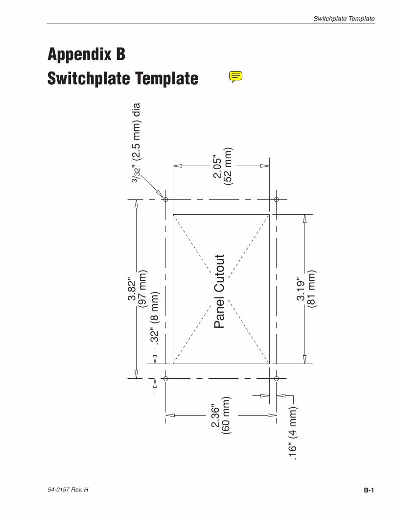
Appendix BSwitchplate Template
B-1
Switchplate Template
54-0157 Rev. H
3.82
"(9
7m
m)
.32"
(8m
m)
2.36
"(6
0m
m)
.16"
(4m
m)
3.19
"(8
1m
m)
2.05
"(5
2m
m)
Pan
elC
utou
t
3 /32
"(2
.5m
m)
dia

KVH Industries, Inc. 50 Enterprise Center Middletown, RI 02842 U.S.A. Phone: +1 401 847-3327 Fax: +1 401 849-0045E-mail: [email protected] Internet: www.kvh.com
KVH Europe A/SKokkedal Industripark 2B 2980 Kokkedal Denmark
Phone: +45 45 160 180 Fax: +45 45 160 181E-mail: [email protected] Internet: www.kvh.com
KVH® and TracVision® are registered trademarks of KVH Industries, Inc.
TVR5
/R4O
M_C
over
11.0
5
®