Embed Size (px)
Citation preview
Sate
llite
Tel
evis
ion
KVH
Trac
Vision
®
L3
owner’s manual• Installation Instructions• User’s Guide• Technical Manual
A Guide to TracVision L3

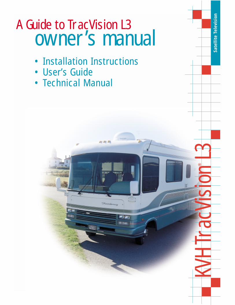
Congratulations!You have selected one of the most advanced land-mobile satellitetracking systems available today. KVH® Industries’ TracVision® L3is designed for use with European and North American DVB-compatible satellite services as well as DIRECTV®. This manualprovides detailed instructions on the proper installation, use, andmaintenance of your TracVision L3 system.
Throughout this manual, important information is marked foryour attention by these icons:
Direct questions, comments, or suggestions to:
KVH Industries, Inc. KVH Europe A/S50 Enterprise Center Ved Klaedebo 12Middletown, RI 02842 USA 2970 Hoersholm Denmarktel: +1 401 847-3327 tel: +45 45 16 01 80fax: +1 401 849-0045 fax: +45 45 86 70 77e-mail: [email protected] e-mail: [email protected]: http://www.kvh.com internet: http://www.kvh.dk
A helpful tip that either directs you to
a related area within the manual or
offers suggestions on getting the
highest quality out of your system.
An alert to important information
regarding procedures, product
specifications, or product use.
An electrical safety warning to help
identify electrical issues that can be a
hazard to either this KVH product or
a user.
Information about installation,
maintenance, troubleshooting, or
other mechanical issues.
KVH Part # 54-0157 Rev. C
© 2000, KVH Industries, Inc.

TracVision® and KVH® are registered trademarks of KVH Industries, Inc.
DIRECTV® is an official trademark of DIRECTV, Inc.,a unit of GM Hughes Electronics.
DISH™ Network is an official trademark of EchoStar Communications Corporation.
ExpressVu is a property of Bell ExpressVu, a wholly ownedsubsidiary of Bell Satellite Services.

Table of Contents1 Introduction . . . . . . . . . . . . . . . . . . . . . . . . . . . . . . .1-11.1 Digital Satellite Television . . . . . . . . . . . . . . . . . . . . . . . . . . . . . .1-1
1.2 TracVision L3 System Overview . . . . . . . . . . . . . . . . . . . . . . . . .1-2
1.2.1 TracVision L3 Components . . . . . . . . . . . . . . . . . . . . . . . . .1-3
1.2.2 Integrated Receiver Decoder . . . . . . . . . . . . . . . . . . . . . . .1-4
1.3 Materials Provided with TracVision L3 . . . . . . . . . . . . . . . . . . . .1-4
1.3.1 Additional Materials required for TracVision L3 Use . . . . . . .1-5
2 Installation . . . . . . . . . . . . . . . . . . . . . . . . . . . . . . . .2-12.1 Choosing the Best Location . . . . . . . . . . . . . . . . . . . . . . . . . . . .2-2
2.2 Mounting the Antenna Unit . . . . . . . . . . . . . . . . . . . . . . . . . . . . .2-2
2.3 Wiring the TracVision L3 System . . . . . . . . . . . . . . . . . . . . . . . .2-6
2.3.1 Wiring the Antenna Data Cable . . . . . . . . . . . . . . . . . . . . . .2-8
2.3.2 Wiring the Antenna Unit Power Cable . . . . . . . . . . . . . . . . .2-9
2.3.3 Connecting to Vehicle Power . . . . . . . . . . . . . . . . . . . . . . .2-10
2.3.4 IRD Ground Wire . . . . . . . . . . . . . . . . . . . . . . . . . . . . . . .2-11
2.3.5 Installing the Switchplate . . . . . . . . . . . . . . . . . . . . . . . . .2-11
2.3.6 Connecting the Antenna RF Signal Cable to the IRD . . . .2-12
2.3.6.1 Installing Two IRDs and TVs (North AmericanSystems Only) . . . . . . . . . . . . . . . . . . . . . . . . . . . . . . .2-13
2.3.6.2 Connecting Three or More IRDs and TVs (North American Systems Only) . . . . . . . . . . . . . . . . . .2-13
2.4 Selecting the Active Satellite . . . . . . . . . . . . . . . . . . . . . . . . . .2-15
2.4.1 Installing Your Selected Satellites . . . . . . . . . . . . . . . . . . .2-16
2.4.2 Programming User-defined Satellites . . . . . . . . . . . . . . . .2-17
2.5 Setting the Skew Angle (European Systems Only) . . . . . . . . .2-21
2.6 Checking Out the System . . . . . . . . . . . . . . . . . . . . . . . . . . . . .2-22
2.7 Configuring TracVision L3 for Remote Satellite Dish Operation . . . . . . . . . . . . . . . . . . . . . . . . . . . . . .2-23
i54-0157 Rev. C

ii
3 Using Your TracVision L3 . . . . . . . . . . . . . . . . . . . . . . .3-13.1 Turning on the System . . . . . . . . . . . . . . . . . . . . . . . . . . . . . . . .3-1
3.2 Changing Channels and Switching to the Second Satellite . . .3-2
3.3 Watching TV on the Move and at Rest . . . . . . . . . . . . . . . . . . . .3-3
4 Troubleshooting . . . . . . . . . . . . . . . . . . . . . . . . . . . . .4-14.1 Causes and Remedies for Common Operational Issues . . . . . .4-1
4.1.1 Blown Fuse or Improper Wiring . . . . . . . . . . . . . . . . . . . . . .4-2
4.1.2 Incorrect Satellite Configuration . . . . . . . . . . . . . . . . . . . . .4-2
4.1.3 Satellite Signal Blocked . . . . . . . . . . . . . . . . . . . . . . . . . . .4-2
4.1.4 Dew or Rain Pooling on Dome . . . . . . . . . . . . . . . . . . . . . .4-3
4.1.5 Outside Satellite Coverage Zone . . . . . . . . . . . . . . . . . . . .4-3
4.1.6 Vehicle Turning During Startup . . . . . . . . . . . . . . . . . . . . . .4-3
4.1.7 Incorrect or Loose RF Connectors . . . . . . . . . . . . . . . . . . .4-3
4.1.8 Using a Passive Multiswitch (North American Systems Only)4-4
4.2 IRD Troubleshooting . . . . . . . . . . . . . . . . . . . . . . . . . . . . . . . . . .4-4
4.2.1 IRD Wiring . . . . . . . . . . . . . . . . . . . . . . . . . . . . . . . . . . . . .4-4
4.2.2 IRD Faulty . . . . . . . . . . . . . . . . . . . . . . . . . . . . . . . . . . . . .4-4
4.3 Antenna Gyro and LNB Faults . . . . . . . . . . . . . . . . . . . . . . . . . .4-4
4.4 Computer Diagnostics . . . . . . . . . . . . . . . . . . . . . . . . . . . . . . . .4-4
4.5 Maintenance Port Parser Commands . . . . . . . . . . . . . . . . . . . . .4-5
5 Maintenance . . . . . . . . . . . . . . . . . . . . . . . . . . . . . . .5-15.1 Warranty/Service Information . . . . . . . . . . . . . . . . . . . . . . . . . . .5-1
5.2 Preventive Maintenance . . . . . . . . . . . . . . . . . . . . . . . . . . . . . . .5-1
5.3 Replaceable Parts . . . . . . . . . . . . . . . . . . . . . . . . . . . . . . . . . . . .5-2
5.4 Field Replaceable Unit Procedures . . . . . . . . . . . . . . . . . . . . . .5-3
5.4.1 PCB Removal and Replacement . . . . . . . . . . . . . . . . . . . . .5-5
5.4.2 RF Detector/DVB Decoder . . . . . . . . . . . . . . . . . . . . . . . . .5-6
5.4.3 Antenna Gyro Assembly . . . . . . . . . . . . . . . . . . . . . . . . . . .5-6
5.4.4 Antenna LNB Replacement . . . . . . . . . . . . . . . . . . . . . . . .5-7
5.5 Preparation for Shipment . . . . . . . . . . . . . . . . . . . . . . . . . . . . . .5-8
Appendix A System Specifications . . . . . . . . . . . . . . . . . .A-1
Appendix B Functional Block Diagram . . . . . . . . . . . . . . . .B-1
Appendix C Switchplate Template . . . . . . . . . . . . . . . . . .C-1
Appendix D Predefined Satellite Configurations . . . . . . . . .D-1
Appendix E Startup Data Sequence . . . . . . . . . . . . . . . . . .E-1
Appendix F Maintenance Port Parser Commands . . . . . . . . .F-1F.1 System Commands . . . . . . . . . . . . . . . . . . . . . . . . . . . . . . . . . . .F-1
F.2 Manual Positioning Commands . . . . . . . . . . . . . . . . . . . . . . . . .F-2
F.3 Operational Commands . . . . . . . . . . . . . . . . . . . . . . . . . . . . . . .F-4
F.4 Tracking and Conical Scan Commands . . . . . . . . . . . . . . . . . . .F-4
F.5 RF Board Commands . . . . . . . . . . . . . . . . . . . . . . . . . . . . . . . . .F-5
F.6 Installation Commands . . . . . . . . . . . . . . . . . . . . . . . . . . . . . . . .F-6
F.7 Debug Commands . . . . . . . . . . . . . . . . . . . . . . . . . . . . . . . . . . .F-8
List of FiguresFigure 1-1 TracVision L3 System Configuration . . . . . . . . . . . . . . . . .1-2
Figure 1-2 Primary Components of the TracVision L3 . . . . . . . . . . . .1-3
Figure 2-1 Proper Orientation of the Antenna Unit . . . . . . . . . . . . . . .2-3
Figure 2-2 Elevation Shipping Restraint . . . . . . . . . . . . . . . . . . . . . . .2-3
Figure 2-3 Baseplate Shipping Restraints . . . . . . . . . . . . . . . . . . . . .2-3
Figure 2-4 Mounting the Unit on a Curved Surface . . . . . . . . . . . . . .2-4
Figure 2-5 Baseplate Dimensions . . . . . . . . . . . . . . . . . . . . . . . . . . .2-4
Figure 2-6 Connectors Facing Rear of Vehicle – Factory-drilled Drain Hole Locations . . . . . . . . . . . . . . . . .2-5
Figure 2-7 Connectors Facing Front of Vehicle – Recommended Drain Hole Locations . . . . . . . . . . . . . . . .2-5
Figure 2-8 Proper Wire-to-Terminal Connection . . . . . . . . . . . . . . . . .2-6
Figure 2-9 Moving the Antenna Reflector . . . . . . . . . . . . . . . . . . . . . .2-6
Figure 2-10 Cable Port Assignments (Exterior of Baseplate) . . . . . . . .2-7
iii54-0157 Rev. C

Figure 2-11 Cable Overlap within the TracVision L3 Baseplate . . . . . . .2-7
Figure 2-12 Switchplate Panel Cutout Dimensions . . . . . . . . . . . . . . . .2-8
Figure 2-13 Proper Terminal Strip Wiring Arrangement – Data Cable . . . . . . . . . . . . . . . . . . . . . . . . . . . . . . . . . .2-8
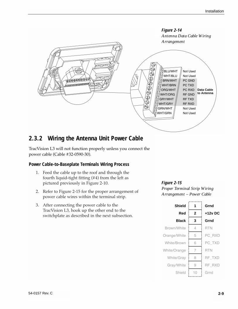
Figure 2-14 Antenna Data Cable Wiring Arrangement . . . . . . . . . . . . .2-9
Figure 2-15 Proper Terminal Strip Wiring Arrangement – Power Cable . . . . . . . . . . . . . . . . . . . . . . . . . . . . . . . . .2-9
Figure 2-16 Power Cable Wiring Arrangement . . . . . . . . . . . . . . . . . .2-10
Figure 2-17 Vehicle Power Wiring Arrangement . . . . . . . . . . . . . . . . .2-10
Figure 2-18 Mounting the Switchplate Support Frame and Front Cover . . . . . . . . . . . . . . . . . . . . . . . . . . . . . . .2-11
Figure 2-19 Connecting the RF Cable to TracVision L3 . . . . . . . . . . .2-12
Figure 2-20a-d Attaching the KVH-provided F-connector to an RF Cable . . . . . . . . . . . . . . . . . . . . . . . . . . . . . . . .2-12
Figure 2-21 Installing Three or More IRDs Using an Active Multiswitch (North American Systems Only) . . . . . . . . . .2-14
Figure 2-22 Skew Adjustment (European Systems Only) . . . . . . . . . .2-21
Figure 2-23 Remote Dish Wiring Configuration . . . . . . . . . . . . . . . . .2-23
Figure 3-1 Be Aware of Objects that Might Block the Satellite Signals . . . . . . . . . . . . . . . . . . . . . . . . . . . . .3-1
Figure 3-2 Turning on the TracVision L3 Using the Switchplate . . . . .3-1
Figure 5-1 Antenna, PCB, and Rotating Plate . . . . . . . . . . . . . . . . . .5-3
Figure 5-2 Close-up of Linear Actuator, Pivot Bracket, and Pin . . . . .5-3
Figure 5-3 Antenna Assembly . . . . . . . . . . . . . . . . . . . . . . . . . . . . . .5-4
Figure 5-4 Close-up of RF Detector and PCB . . . . . . . . . . . . . . . . . .5-4
Figure 5-5 PCB and RF Detector Board Connector Locations . . . . . .5-5
Figure 5-6 LNB Skew Angle Setting (European Systems Only) . . . . .5-7
Figure 5-7 Attaching the Shipping Restraints to the Antenna Baseplate . . . . . . . . . . . . . . . . . . . . . . . . . . . . . .5-8
Figure 5-8 Placing the Elevation Axis Shaft Restraint . . . . . . . . . . . . .5-8
Figure 5-9 Securing the Elevation Axis Shaft Restraint . . . . . . . . . . .5-9
Figure 5-10 Repackaging the TracVision L3 . . . . . . . . . . . . . . . . . . . . .5-9
iv

List of TablesTable 1-1 Available European Satellite Pairs
(European LNB Required) . . . . . . . . . . . . . . . . . . . . . . .1-1
Table 1-2 Available N. American Satellite Pairs (U.S.-style LNB required0 . . . . . . . . . . . . . . . . . . . . . . .1-2
Table 1-3 TracVision L3 Packing List . . . . . . . . . . . . . . . . . . . . . . .1-4
Table 2-1 Installation Process . . . . . . . . . . . . . . . . . . . . . . . . . . . .2-1
Table 2-2 Kitpack Contents . . . . . . . . . . . . . . . . . . . . . . . . . . . . . .2-2
Table 2-3 Available European Satellite Pairs (European LNB Required) . . . . . . . . . . . . . . . . . . . . . .2-15
Table 2-4 Available N. American Satellite Pairs (U.S.-style LNB Required) . . . . . . . . . . . . . . . . . . . . . .2-15
Table 2-5 Satellite Installation Names . . . . . . . . . . . . . . . . . . . . .2-17
Table 2-6 Default Transponder Values . . . . . . . . . . . . . . . . . . . . .2-19
Table 2-7 Sample User-defined Satellite Configuration . . . . . . . .2-20
Table 4-1 Troubleshooting Matrix . . . . . . . . . . . . . . . . . . . . . . . . .4-1
Table 5-1 Field Replaceable Units . . . . . . . . . . . . . . . . . . . . . . . .5-2
Table A-1 TracVision L3 System Specifications . . . . . . . . . . . . . . .A-1
Table F-1 System Commands . . . . . . . . . . . . . . . . . . . . . . . . . . . .F-1
Table F-2 Manual Positioning Commands . . . . . . . . . . . . . . . . . . .F-2
Table F-3 Operational Commands . . . . . . . . . . . . . . . . . . . . . . . .F-4
Table F-4 Tracking and Conical Scan Commands . . . . . . . . . . . . .F-4
Table F-5 RF Board Commands . . . . . . . . . . . . . . . . . . . . . . . . . .F-5
Table F-6 Installation Commands . . . . . . . . . . . . . . . . . . . . . . . . .F-7
Table F-7 Debug Commands . . . . . . . . . . . . . . . . . . . . . . . . . . . .F-8
v54-0157 Rev. C

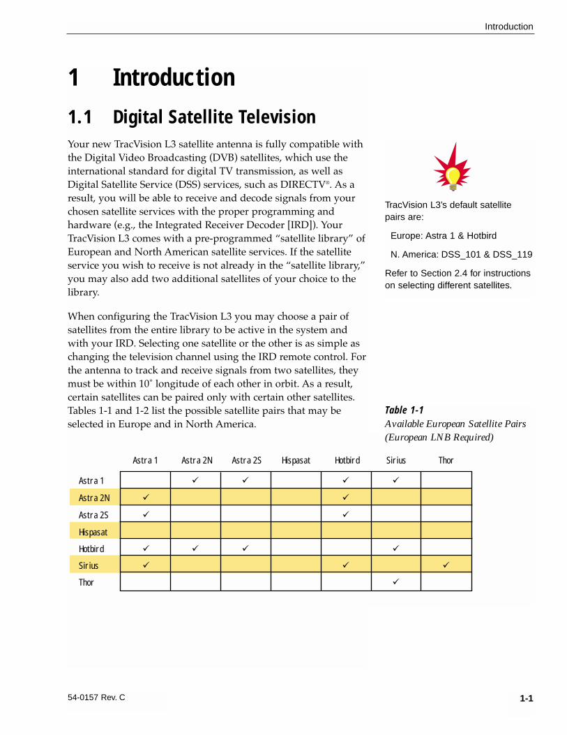
1 Introduction1.1 Digital Satellite TelevisionYour new TracVision L3 satellite antenna is fully compatible withthe Digital Video Broadcasting (DVB) satellites, which use theinternational standard for digital TV transmission, as well asDigital Satellite Service (DSS) services, such as DIRECTV®. As aresult, you will be able to receive and decode signals from yourchosen satellite services with the proper programming andhardware (e.g., the Integrated Receiver Decoder [IRD]). YourTracVision L3 comes with a pre-programmed “satellite library” ofEuropean and North American satellite services. If the satelliteservice you wish to receive is not already in the “satellite library,”you may also add two additional satellites of your choice to thelibrary.
When configuring the TracVision L3 you may choose a pair ofsatellites from the entire library to be active in the system andwith your IRD. Selecting one satellite or the other is as simple aschanging the television channel using the IRD remote control. Forthe antenna to track and receive signals from two satellites, theymust be within 10˚ longitude of each other in orbit. As a result,certain satellites can be paired only with certain other satellites.Tables 1-1 and 1-2 list the possible satellite pairs that may beselected in Europe and in North America.
1-1
Introduction
54-0157 Rev. C
Astra 1 ü ü ü ü
Astra 2N ü ü
Astra 2S ü ü
Hispasat
Hotbird ü ü ü ü
Sirius ü ü ü
Thor ü
Astra 1 Astra 2N Astra 2S Hispasat Hotbird Sirius Thor
Table 1-1Available European Satellite Pairs(European LNB Required)
TracVision L3’s default satellitepairs are:
Europe: Astra 1 & Hotbird
N. America: DSS_101 & DSS_119
Refer to Section 2.4 for instructionson selecting different satellites.

1.2 TracVision L3 System OverviewYour TracVision L3 employs a state-of-the-art actively stabilizedantenna system. Once the satellite is acquired, the antenna gyrocontinuously measures your vehicle’s motion and position, andtransmits commands to the antenna motors to keep the antennapointed at the satellite at all times. A complete satellite TV systemincludes the TracVision L3 connected to an IRD, and a televisionset. A desktop or laptop computer is used to configure the systemfor satellite selection and conduct diagnostics. The system isillustrated in Figure 1-1.
1-2
A Guide to TracVision L3
11-16 Volts DC
2.5-3.5 Amps
Satellite Receiver 1
Data Cable
RF�Coaxial�Cables
Options Purchased Separately
TV 1
TracVision L3 Antenna
Power Cable
Vehicle�
PowerSwitchplate
PC Maintenance
Port
Satellite Receiver 2TV 2 Laptop PC
Second TV and receiver option only available with U.S.-style, dual output LNB.
Figure 1-1TracVision L3 System
Configuration
DSS_101 ü
DSS_110*
DSS_119 ü
Echo_61 ü ü ü
Echo_110 ü ü ü ü
Echo_119 ü ü ü ü
Echo_148 ü ü ü
Expressvu ü ü ü ü
DSS_101 DSS_110 DSS_119 Echo_61 Echo_110 Echo_119 Echo_148 Expressvu
* Contact KVH or DIRECTV for complete details on tracking and receiving signals from DSS_110.
Table 1-2Available N. American SatellitePairs (U.S.-style LNB required)

System specifications and a functional block diagram areprovided in Appendices A and B, respectively.
1.2.1 TracVision L3 ComponentsThe Antenna Unit includes the antenna positioning mechanism,signal front end, power supply and control elements. Theantenna is a parabolic dish mounting a low noise block (LNB)converter with built-in preamplifier. The European configurationincludes a single port LNB while the North American systemuses a dual-output LNB. A molded ABS radome encloses thebaseplate and is secured in place with standard fasteners. Liquid-tight (watertight) fittings located on the back of the baseplate jointhe power, signal, and control cabling from below-decks units.
1-3
Introduction
54-0157 Rev. C
Figure 1-2Primary Components of theTracVision L3
Radome
Antenna Unit
Mounting Plate
Antenna
Reflector
LNB Bracket
Gyro
RF DVB�
Decoder PCB
System�
Control�
PCB
North American LNB European LNB
Always lift the Antenna Unit by thegray baseplate and not the radome,antenna reflector, or internalmechanical assemblies.
NEVER pick up the unit by theLNB or the gyro!

1.2.2 Integrated Receiver DecoderThe IRD (purchased separately) receives satellite signals from theAntenna Unit for signal processing and channel selection, andsends the signals to the TV set for viewing. The IRD alsoprovides the interface for the user to activate authorization forreception. Please refer to the User’s Manual provided with yourselected IRD for complete operating instructions.
1.3 Materials Provided withTracVision L3
Table 1-3 lists the units, cables, and materials packed in theTracVision L3 package by name and KVH part number.
Component KVH Part No.
Antenna Unit (comprising): 01-0225-03
Baseplate Assembly 02-1044-01
Radome Assembly 02-0953-03
RF Cable 32-0589-30
Power Cable 32-0590-30
Antenna Data Cable 32-0630-30
PC Cable 32-0628-06
Mounting Plate 20-0668
Kitpack* 72-0101
Installation and Operation Manual 54-0157
IRD Ground Wire 32-0583-30
Switchplate 02-1023
* A complete listing of kitpack contents is provided in Section 2.2, “Mounting theAntenna Unit.”
1-4
A Guide to TracVision L3
Table 1-3TracVision L3 Packing List
Cables for the TracVision L3 arestored beneath the Antenna Unitduring shipping.
The dual-output LNB in the NorthAmerican systems allows twoIRD/TV pairs to be connecteddirectly to the antenna. Three ormore pairs can be connected to thesystem if an active multiswitch isused. Section 2.3.6, “Connectingthe Antenna RF Signal Cable to theIRD,” provides installation directionsfor each of these options.

1.3.1 Additional Materials Required forTracVision L3 Use
To make full use of your new TracVision L3 and receive satelliteTV on the road, you will need to provide/purchase thefollowing:
• Television
• Appropriate IRD for your selected satellite TV service, and
• Sealing materials to weatherproof cable holes andseal mounting plate.
1-5
Introduction
54-0157 Rev. C


2-1
Installation
54-0157 Rev. C
2 InstallationTracVision L3 is designed for simple installation and setup. Justfollow these easy steps:
Step Refer to Section...
1. Choose the hardware locations 2.1
2. Mount the Antenna Unit 2.2
3. Wire system components 2.3
4. Select active satellite 2.4
5. Set the skew angle (Europe only) 2.5
6. Check out system 2.6
7. Configure for remote dish use 2.7
Installation Tools and Materials Required
• Electric drill
• 3⁄16" (5 mm) and 3⁄32" (2 mm) drill bits and 1⁄2" (13 mm) hole saw and auger bit
• 1⁄2" (13 mm) socket wrench
• #2 Phillips and #0 flat tip screwdrivers
• Augat Snap ‘n Seal Crimp/Strip Tool (PartNumber IT1000) if using the KVH-provided F-connector
• Silicone sealant, RTV, or Sikaflex
• Thread locker (as required)
• 7⁄16" (11 mm) open end wrench
• Wire strippers
• Construction adhesive (e.g., Liquid Nails)
• Rivet gun and 3⁄16" (5 mm) rivets (or other fastenersuitable for specific roof construction)
• PC with terminal emulation software such asPROCOMM, Windows Terminal, or Windows95/98 Hyperterminal
Plan the entire installation beforeproceeding! Take into accountcomponent placement, runningcable distances between units, andaccessibility to the equipment afterinstallation.
Table 2-1Installation Process

2-2
A Guide to TracVision L3
2.1 Choosing the Best Location• The ideal antenna site has a clear view of the
horizon/satellite all around.
• Keep the antenna clear of any obstructions on theroof (e.g., air conditioners).
• Consider the location of the antenna relative to thelocation of any equipment or necessary wiringwithin the vehicle.
• For best operation, mount the antenna on ahorizontal surface.
2.2 Mounting the Antenna UnitThe following instructions will result in a secure, effectiveinstallation and trouble-free operation of your TracVision L3.Table 2-2 lists the materials provided in the TracVision L3kitpack. Most of these components will be used in the installationprocess.
Part Qty. KVH Part No.
RF F-Connector 1 23-0170
Tie-wrap 5 22-0013
Flash kit cable and adapter 1 02-1029
Antenna Mounting Procedure
1. Remove Antenna Unit from shipping container.
2. Remove and save 8 pan head screws and flatwashers that hold radome to baseplate. Carefullylift radome straight up until clear of antennaassembly and set aside.
3. Position Antenna Unit in desired location on thecenterline of the vehicle with baseplate andmounting plate arrows facing in the samedirection (either forward or backward). The properorientation is illustrated in Figure 2-1 on thefollowing page.
Table 2-2Kitpack Contents
Always lift the Antenna Unit bythe gray baseplate, never by theradome or any portion of theantenna assembly!
The liquid-tight connectors onTracVision L3 may face eitherforward or backward along thecenterline of the vehicle for moreconvenient installation.

2-3
Installation
54-0157 Rev. C
4. While baseplate is in place, mark location(s) onroof for cable access to permit convenient cableaccess to the liquid-tight fittings on the back of thebaseplate.
5. Cut the tie-wraps holding the foam elevationshipping restraint to the elevation axis motor shaft(pictured in Figure 2-2) and remove the restraint.
6. Remove the three foam baseplate shippingrestraints securing the rotating plate, pictured inFigure 2-3.
7. Remove six 1⁄4-20 hex nuts and washers that securethe Antenna Unit to the mounting plate.
8. Remove Antenna Unit from mounting plate.
9. The mounting plate allows the Antenna Unit to bemounted on a curved roof. While the perimeter ofthe mounting plate is secured to the vehicle with
Figure 2-1Proper Orientation of the Antenna Unit
VehicleCenterline
Do not discard the foam shippingrestraints or shipping box. Theyshould be saved for future use incase the Antenna Unit needs to beremoved and shipped to anotherlocation.
Figure 2-3Baseplate Shipping Restraints
Figure 2-2Elevation Shipping Restraint

2-4
A Guide to TracVision L3
the appropriate fasteners, two flexible wings allowthe rear mounting bolts to attach to the antennabaseplate. These may be angled upward to ensurea secure mounting, as shown in Figure 2-4.
10. Using the mounting plate as a template, drill four3⁄16" (5 mm)-holes through the roof of the vehicle ateach of the four corners. Temporarily secure themounting plate at the corners with rivets orscrews.
11. With the corners secured, use the mounting plateas a template to mark and drill the remainingnineteen 3⁄16" (5 mm)-holes through the roof of thevehicle. Remove plate and clean roof surface. Thedimensions of the baseplate and locations of thedrill holes are shown in Figure 2-5.
12. Place the construction adhesive over all holes. Ifusing a liquid construction adhesive, apply beadto mounting plate in a zig-zag pattern.
Figure 2-4Mounting the Unit on a
Curved Surface
Antenna Baseplate bolts to this “wing,”which can remain horizontal.
MountingPlate Wing
Mounting Plate can be tightened down to conform to a curved surface.
24.0" (610 mm)
28.8"
(731 mm)
Figure 2-5Baseplate Dimensions

2-5
Installation
54-0157 Rev. C
13. Reposition mounting plate over adhesive andattach using 3⁄16" (5 mm)-diameter rivets (orappropriate fasteners). Seal all rivet heads andedges with silicone.
14. Drill cable access hole(s) in vehicle.
15. When unit is installed with connectors facing therear of the vehicle, the drain holes are located asshown in Figure 2-6.
Figure 2-6Connectors Facing Rear of Vehicle – Factory-drilledDrain Hole Locations
Factory-drilled
Drain Hole Positions
Front of
Vehicle
Recommended
3/16" (5 mm)
Drain Hole Positions
Drain Hole Angle
(relative to baseplate)
Front of
Vehicle
Angle of Hole, relative to front
Angle of Hole, relative to front
Figure 2-7Connectors Facing Front of Vehicle – Recommended Drain Hole Locations
You MUST drill out the drain holesas indicated to ensure that anymoisture that enters the baseplateis able to drain. Ensure thatfactory-drilled holes are completelysealed.
15a.(Alternate Drain Holes) If the Antenna Unit isinstalled with the connectors facing the front of thevehicle, drill out 3⁄16" (5 mm)-drain holes in rear-facing side of baseplate as illustrated in Figure 2-7.The existing factory-drilled drain holes shown inFigure 2-6 must then be plugged with siliconerubber sealant.

2-6
A Guide to TracVision L3
16. Place Antenna Unit on mounting plate and secureusing nuts and washers removed in Step 7.
17. Proceed to Section 2.3, “Wiring the TracVision L3System,” to wire the TracVision L3 system. Theradome will be placed back on the baseplate usingthe hardware removed in Step 2 after wiring andinitializing the system.
2.3 Wiring the TracVision L3 SystemThe following sections provide instructions for properly wiringthe Antenna Unit to the IRD and to vehicle power.
Tips for Safe and Successful Wiring within the TracVision L3 Baseplate
• When attaching cables to the TracVision L3terminal connector strips, make sure the insulationis stripped back approximately 1⁄4" (6 mm) asillustrated in Figure 2-8. Twist the wires gently tohelp achieve a good connection. Do not pinchinsulation inside the connector.
• After attaching the power and data cables to theappropriate terminal connector strips, tug gentlyto ensure a firm connection.
• After attaching cables within the TracVision L3baseplate, eliminate any unnecessary slack in thecables before tightening the liquid-tight fittings.
• Run the RF signal cable into the baseplate last. Itwill help keep the power and data cables clear ofthe antenna and LNB.
• After hooking up all of the wiring and removing anyslack, slowly rotate the antenna while raising andlowering the reflector to make certain that the cablesare all clear of any moving elements as pictured inFigure 2-9.
• Check to be certain that the elevation axis actuatormotor shaft (pictured in Section 5, Maintenance,Figure 5-2) clears all cable connections.
• Completely seal all rooftop cable access holes.
Figure 2-9Moving the Antenna Reflector
Figure 2-8Proper Wire-to-Terminal
Connection
Insulation
Terminal Connector
1/4" (6 mm)
DO NOT leave an extra length ofcable within the baseplate as aservice loop. All service loopsshould be stored within thevehicle’s cable access.

2-7
Installation
54-0157 Rev. C
TracVision L3 Cable Ports
On one side of the baseplate are four liquid-tight fittings, whichserve the dual purpose of relieving strain on the cables as well asproviding a tight seal around the cable access ports.
When wiring is done properly, the sets of cables will overlap eachother, as illustrated in Figure 2-11.
A switchplate has been provided to serve as the hub of theTracVision L3 wiring (with the exception of the RF cable, whichwill be connected to the IRD). This switchplate includes anON/OFF switch and a DB9 maintenance port for easy access tothe Antenna Unit’s software and diagnostics. Follow these stepsto begin the wiring process.
1. Select a location to mount the TracVision L3switchplate. It should be flat and within reach ofthe cables connected to the Antenna Unit.
2. Create a panel cutout in the mounting surface.Figure 2-12 on the following page illustrates themounting dimensions and a template has beenprovided in Appendix C.
Figure 2-10Cable Port Assignments (Exterior of Baseplate)
RF(#1)
Used only withN. American Systems
Power(#4)
RF(#2)
Data(#3)
Data
Power
RF CableFigure 2-11Cable Overlap within theTracVision L3 Baseplate

2-8
A Guide to TracVision L3
3. Run the Antenna power and data cables from theAntenna Unit and out through the panel cutout.
4. Run a cable from vehicle’s power (11-16 Vdc)through the panel cutout.
You are now ready to wire the TracVision L3 system to theswitchplate connectors and vehicle power.
2.3.1 Wiring the Antenna Data Cable TracVision L3 will not function properly unless you connect theantenna data cable (Cable #32-0630-30).
Antenna Data Cable-to-Baseplate Terminals Wiring Process
1. Feed the cable up to the roof and through the thirdliquid-tight fitting (#3) from the left as pictured inFigure 2-10.
2. Refer to Figure 2-13 for the proper arrangement ofdata cable wires within the terminal strip.
3. After connecting the antenna data cable to the TracVision L3, hook up the other end to theswitchplate as described in the next subsection.
Antenna Data Cable-to-Switchplate Wiring Process
Find the TracVision L3 antenna data cable (Cable #32-0630-30)where it comes through the panel cutout made earlier. Wire theantenna data cable to the switchplate connectors as indicated inFigure 2-14 on the next page. The connector board is etched withthe wire color identification to make the wiring process easier.
Shield
Red
Black
Brown/White
Orange/White
White/Brown
White/Orange
White/Gray
Gray/White
Shield
Grnd
+12v DC
Grnd
RTN
PC_RXD
PC_TXD
RTN
RF_TXD
RF_RXD
Grnd
1
2
3
4
5
6
7
8
9
10
Figure 2-13Proper Terminal Strip Wiring
Arrangement – Data Cable
3.82"(97 mm)
.32" (8 mm)
2.36"(60 mm)
.16" (4 mm)3.19"
(81 mm)
2.05"(52 mm)
Panel Cutout
3/32" (3 mm) diaFigure 2-12Switchplate Panel
Cutout Dimensions
A full-scale panel cutout templatehas been provided in Appendix C.
2-9
Installation
54-0157 Rev. C
2.3.2 Wiring the Antenna Unit Power CableTracVision L3 will not function properly unless you connect thepower cable (Cable #32-0590-30).
Power Cable-to-Baseplate Terminals Wiring Process
1. Feed the cable up to the roof and through thefourth liquid-tight fitting (#4) from the left aspictured previously in Figure 2-10.
2. Refer to Figure 2-15 for the proper arrangement ofpower cable wires within the terminal strip.
3. After connecting the power cable to the TracVision L3, hook up the other end to theswitchplate as described in the next subsection.
BLU/WHT Not Used
WHT/BLU Not Used
BRN/WHT PC GND
WHT/BRN PC TXD
ORG/WHT PC RXD
WHT/ORG RF GND
GRY/WHT RF TXD
WHT/GRY RF RXD
GRN/WHT Not Used
WHT/GRN Not Used
Data Cable to Antenna
Figure 2-14Antenna Data Cable WiringArrangement
Shield
Red
Black
Brown/White
Orange/White
White/Brown
White/Orange
White/Gray
Gray/White
Shield
Grnd
+12v DC
Grnd
RTN
PC_RXD
PC_TXD
RTN
RF_TXD
RF_RXD
Grnd
1
2
3
4
5
6
7
8
9
10
Figure 2-15Proper Terminal Strip WiringArrangement – Power Cable

2-10
A Guide to TracVision L3
Power Cable-to-Switchplate Wiring Process
Find the TracVision L3 power cable (Cable #32-0590-30) where itcomes through the panel cutout made earlier. Wire the AntennaUnit power cable to the switchplate connectors as indicated inFigure 2-16. After wiring the power cable, connect the powerindicator lamp, also as noted in Figure 2-16. After both the powercable and lamp are properly wired, carefully insert the lamp intoits socket immediately below the switchplate connectors.
2.3.3 Connecting to Vehicle PowerAfter completely wiring the indicator lamp and the data andantenna cables, you must connect the switchplate to vehiclepower as pictured in Figure 2-17.
+12 Vdc (Red) Ð Cable #32-0590-30
+12 Vdc Ð Lamp
Ground (Black) Ð Cable #32-0590-30
Ground Ð Lamp
Lamp Socket
+12 Vdc Ð Vehicle Power
Ground Ð Vehicle Power
Before connecting the Antenna Unitto vehicle power, remove theappropriate vehicle fuse to preventa short circuit. After connecting tovehicle power, replace the fuse.
Figure 2-16Power Cable Wiring Arrangement
Figure 2-17Vehicle Power Wiring
Arrangement
Make sure that all wires aresecurely fastened within theswitchplate connectors.

2-11
Installation
54-0157 Rev. C
2.3.4 IRD Ground WireA grounding wire (Cable #32-0583-50) has been provided toconnect your IRD to a suitable ground and protect the system.Attach the grounding wire to any suitable screw on the rearpanel of the IRD with a good contact with the IRD chassis. Theother end should be connected to a suitable ground, such as thevehicle’s power ground wire connected to the switchplate.
2.3.5 Installing the SwitchplateAfter completing the switchplate wiring process, you must installthe switchplate itself. This process, detailed in the followingsteps, is illustrated in Figure 2-18.
1. Fit the switchplate assembly and support frameinto the panel cutout made in Step 2 in Section 2.3and flush to the mounting surface.
2. Drill out four 5⁄32" (4 mm) holes in the countersunksettings in the switchplate support frame.
3. Drill four 3⁄32" (2 mm) holes in the mounting surfaceusing the countersunk holes in the support frameas the template. Secure the support frame andswitchplate assembly to the mounting surfaceusing the four #6 self-cutting screws.
4. Snap the front cover into place to cover the screwsand support frame.
3.82"�(97 mm)
2.36"�(60 mm)
2.05"�(52 mm)
3.19"�(81 mm)
A. Panel Cutout
B. Support Frame
C. Front Cover
5/32" (4 mm)3/32" (2.5 mm)
Figure 2-18Mounting the Switchplate Support Frame and Front Cover
Before securing the switchplate tothe mounting surface, be sure tostrain relieve the wires connectingto the switchplate connectors.Several tie-wraps have beenprovided to aid in strain relievingthe wires.

2-12
A Guide to TracVision L3
2.3.6 Connecting the Antenna RF Signal Cable to the IRD
The RF signal cable is fitted with an F-type connector at only oneend and should be attached to TracVision L3 and the IRD asfollows:
1. Feed the bare end of the RF signal cable throughthe #2 liquid-tight fitting at the back of theTracVision L3 baseplate and away from the dome,leaving the F-connector inside the TracVision L3baseplate (as pictured in Figure 2-19).
2. Connect the RF signal cable’s F-connector to theplug labeled RF1.
3. Feed the bare end of the RF signal cable and passthrough the cable hole drilled earlier and into thevehicle.
4. Attach the provided F-connector to the end of theRF signal cable inside the vehicle as illustrated inFigure 2-20a-d, using an Augat Snap ‘n SealCrimp/Strip tool to lock the connector on thecable.
A. Slide compression fitting onto raw cable before beginning connector termination.
Figure 2-20a-dAttaching the KVH-provided
F-connector to an RF Cable
KVH has provided an F-connectorfor use with the TracVision L3. Thisconnector specifically requires theAugat Snap ‘n Seal Crimp/StripTool, part number IT1000.
If you do not have this tool, you willneed to purchase a silicone-filled,weatherproof F-connector (RadioShack part number 278-236 orequivalent) to use instead.
Figure 2-19Connecting the RF Cable
to TracVision L3
Entry Port for
RF1 Connector
RF1
To Vehicle
When shipped from the factory, the#1 liquid-tight fitting is sealed with arubber stopper. Leave the stopperin the fitting.

2-13
Installation
54-0157 Rev. C
B. Twist and break off connector body.
C. Use the Augat tool to strip the centerconductor and trim back the overall jacket. Donot cut through the braid.
D. Slide connector body onto the prepared cable.Slide the compression fitting up into theconnector body. Use Augat tool to snap on theconnector.
5. Attach the cable to the IRD connector labeledSATELLITE IN.
2.3.6.1 Installing Two IRDs and TVs (North American Systems Only)
To connect a second TV and IRD to the TracVision L3 system, youmust connect a second RF cable to the RF2 connector within theAntenna Unit baseplate. The other end of the RF cable should berun down into the vehicle and connected directly to the secondIRD. Each IRD/TV pair can operate independently of the other,allowing different viewers to watch different channels.
2.3.6.2 Connecting Three or More IRDs andTVs (North American Systems Only)
To install three or more IRD/TV pairs, an active multiswitch(Channel Master model 6214IFD or equivalent) is placed betweenthe Antenna Unit and the IRDs. Figure 2-21 on the followingpage illustrates typical wiring arrangements for multiple IRDs. Ifmore than four IRDs are required, contact KVH for additionalwiring instructions. Mount the multiswitch unit in accordancewith the manufacturer’s instruction sheet.
Twist
0.25" (6 mm)
0.25" (6 mm)
KVH recommends the use of RG-6 or RG-11 (75 ohms) cable for RF wiring. Use of non-RG-6 or RG-11 (75 ohms) cables willresult in degraded performance.The KVH warranty does not coverdegraded performance due toimproper wiring.

1. Connect the RF cable tagged “RF1” to themultiswitch input labeled “LNB RHCP +13V”.
2. Connect a second RF cable to the multiswitchinput labeled “LNB LHCP +18V”.
3. Connect the multiswitch outputs to individual IRDinputs. Use RG-6 cable terminated with F-type connectors for all RF connections.
4. Terminate all unused output connectors with 75 ohm DC blocks (Channel Master #7184, RadioShack #15-1259 or equivalent).
Commissioning the IRD
Please refer to the user manual that accompanied your IRD forinstructions on properly commissioning the system.
2-14
A Guide to TracVision L3
Multiswitch
DC In RHCP
+13v
VHF/UHF LHCP
+18v
Out 1 Out 2 Out 3 Out 4
DC Power
IRD #1 IRD #2 IRD #4IRD #3
TracVision L3 RF Connectors
RF1
RF2
Figure 2-21Installing Three or More IRDsUsing an Active Multiswitch
(North American Systems Only)
TracVision L3 has the capability toswitch from one satellite to anotherwhen you choose TV channels thatare carried by your two selectedsatellites. However, the use of anactive multiswitch may interfere withthe 22 KHz tone sent byDIRECTV+ IRDs to the antenna. Asa result, the antenna may notreceive the signal to changesatellites when you changechannels using your DIRECTV+remote.
In this case, you will need to usethe manual satellite switchprocedure explained in Section 3.2,“Changing Channels and Switchingto the Second Satellite.”

2.4 Selecting the Active SatelliteAs noted previously, TracVision L3 can track a variety of DVB-compatible and DSS satellites. The system contains apreprogrammed library of European and North Americansatellites. It also has two open slots that you may use to programtwo additional satellites of your choice. Tables 2-3 and 2-4provide a grid of possible satellite pairs. Two of these satellitesmay be selected to reside in the system’s active memory asSatellites A and B. Once this is done, changing the channel on theIRD remote control will tell the antenna to track one or the other,making it easy to switch between the satellites of your choice.
The satellites listed in TracVision L3’s preprogrammed satellitelibrary will be sufficient for most users. However, if you wish toinstall one or two user-defined satellites, proceed to Section 2.4.2,
2-15
Installation
54-0157 Rev. C
Astra 1 ü ü ü ü
Astra 2N ü ü
Astra 2S ü ü
Hispasat
Hotbird ü ü ü ü
Sirius ü ü ü
Thor ü
Astra 1 Astra 2N Astra 2S Hispasat Hotbird Sirius Thor
Table 2-3Available European Satellite Pairs(European LNB Required)
DSS_101 ü
DSS_110*
DSS_119 ü
Echo_61 ü ü ü
Echo_110 ü ü ü ü
Echo_119 ü ü ü ü
Echo_148 ü ü ü
Expressvu ü ü ü ü
DSS_101 DSS_110 DSS_119 Echo_61 Echo_110 Echo_119 Echo_148 Expressvu
* Contact KVH or DIRECTV for complete details on tracking and receiving signals from DSS_110.
Table 2-4Available N. American SatellitePairs (U.S.-style LNB Required)

“Programming User-defined Satellites.” After configuring the user-defined satellites, return to the satellite installation process inSection 2.4.1, “Installing Your Selected Satellites.”
2.4.1 Installing Your Selected SatellitesWhen you first connect to the system, it is programmed with thefactory default satellite assignments:
• Europe: Astra 1 (Sat. A) and Hotbird (Sat. B)
• N. America: DSS_101 (Sat. A) and DSS_119 (Sat. B)
Should you wish to track a different satellite (either from thesatellite library or a user-defined satellite), you must instruct theantenna which satellites will be in the active satellite pair.
Connecting to the TracVision L3 Maintenance Port
To do so, it is necessary to connect a PC to the terminalmaintenance port on the switchplate. The diagnostics procedurerequires terminal emulation software such as PROCOMM,Windows Terminal, or Windows 95/98 Hyperterminal. Use thesettings appropriate to your application.
1. Connect one end of the PC data cable to the DB9connector on the switchplate. Connect the otherend to the serial port on the PC (a 9-pin/25-pinconnector adapter may be needed for some PCs).
2. Open the terminal emulation software andestablish the following settings:
• 9600 baud
• no parity
• 8 data bits
• 1 start bit
• 1 stop bit
• no flow control
3. Apply power to the TracVision L3 system andallow the system to complete full initialization.Data should be scrolling on the PC display toidentify any system problems detected. If no datais seen, recheck your connections and the terminalsoftware setup.
2-16
A Guide to TracVision L3
The satellite configuration onyour IRD must match the satellitesetting on the TracVision L3system.
Satellite A on the TracVision L3must be the same satellite as IRDAlternative 1 (or A, based on yourIRD) and must be assigned the IRDDiSEqC 1 setting.
Satellite B on the TracVision L3must be the same satellite as IRDAlternative 2 (or B, based on yourIRD) and must be assigned the IRDDiSEqC 2 setting.
Refer to your IRD user manual forcomplete instructions for your IRD.

Installing the Satellite of Choice
Once the data connection has been made between the PC and theTracVision L3, you must assign the satellites you wish to have inthe satellite pair. On the maintenance screen, put the antenna inIdle Mode by typing HALT, then enter the SATINSTALLcommand:
Command: SATINSTALL,<sat_a_name>,<sat_b_name><cr>
Where: <sat_a_name> = the name of your choice for Satellite A
<sat_b_name> = the name of your choice for Satellite B
Table 2-5 lists the assigned names for satellites that are in thepreprogrammed European satellite library. If you do not wish toassign a pair of satellites, enter None as the name of Satellite B.
After you have assigned satellites as Satellites A and B, the finalstep is to tell the antenna which of the two satellites it shouldacquire and track. This step should be carried out the first time asatellite is selected, allowing the system to carry out the initialdownload of the channel guide. To do so, enter the SatelliteSelection parser command as follows:
Command: @L,x<cr>
Where: x = A or B (one of your selected satellites as defined during the SATINSTALL process)
Choosing A or B will assign the antenna to acquire and track thatinstalled satellite. To complete the process, type ZAP<cr> torestart the system. Be sure the IRD satellite configuration matchesyour chosen TracVision L3 settings.
2.4.2 Programming User-defined SatellitesThe TracVision L3 satellite library has two open slots that youmay use to program two user-defined satellites in case you wantto install/watch a satellite that is not in the KVH predefined list.To configure a user satellite, the system must first be in IdleMode (by typing HALT) and then information about the satellitemust be provided, including:
• Satellite name
• Satellite position (longitude)
2-17
Installation
54-0157 Rev. C
Satellite Install Name
European Satellites
ASTRA1 19.2˚E ASTRA1
ASTRA2N 28.2˚E ASTRA2N
ASTRA2S 28.2˚E ASTRA2S
Hispasat 30.0˚W HISPASAT
Hotbird 13.0˚E HOTBIRD
Sirius 5.0˚E SIRIUS
Thor 0.8˚W THOR
North American Satellites
DSS 101˚ W DSS_101
DSS 110˚ W DSS_110
DSS 119˚ W DSS_119
EchoStar 61˚ W Echo_61
EchoStar 110˚ W Echo_110
EchoStar 119˚ W Echo_119
EchoStar 148˚ W Echo_148
ExpressVu Expressvu
Other Installation Designations
User-defined 1 USER1*
User-defined 2 USER2*
None None
* USER1 and USER2 will only beavailable if one or two user-definedsatellites have been added to thelibrary as detailed in Section 2.4.2,“Programming User-defined Satellites.”
Table 2-5Satellite Installation Names

• Transponder information for each of the followingpolarizations/frequencies:
- vertical high & vertical low
- horizontal high & horizontal low
• Transponder information includes:
- frequency
- symbol rate
- FEC code, and
- network ID (in hexidecimal format)
• Decoder type
This information can be obtained from your satellite serviceprovider or from sites on the Internet, such as www.satcodx.com.For your reference, the satellite configuration information for thepredefined satellites has been provided in Appendix D.
Entering User-defined Satellite Data
Once the link between the PC and the TracVision L3 isestablished as described in Section 2.4, “Selecting the ActiveSatellite,” it is necessary to provide initial longitude dataregarding the user-defined satellite. To do so, enter theSATCONFIG parser command via PC as follows:
Command: SATCONFIG,USERX,YYY,Z,D,L<cr>
Where: X = 1 or 2 (satellite alternative)
YYY = longitude (0-180)
Z = E (East) or W (West)
D = decoding type (0=test, 1=DSS-A, 2=DSS-B,3=DVB)
L = LNB polarization (C=circular, L=linear)
Function: configures one of the user-configurable satelliteswith the longitude provided
Response: if valid entry, echoes the input dataif invalid entry, returns error message
2-18
A Guide to TracVision L3

After entering the SATCONFIG command, you must turn on theDEBUG mode by typing @DEBUGON. Following the entry ofthe SATCONFIG and DEBUGON commands, enter the satellitetransponder information via PC as follows:
Command: @SATCONFIG,X,N,F,S,C,ID,P,B,D<cr>
Where: @SATCONFIG = directs data to the RF Board
X = satellite location A or B
N = satellite table # (98 & 99 are slots for user-configured satellites)
F = frequency in MHz (either 00000 or a range from10700 - 12700)
S = the satellite transponder symbol rate inMbit/second (01000 - 29999)
C = the FEC code (e.g., 12, 23, 34, 56, 67, 78)
ID = the satellite network ID in hexidecimal format(0x####)
P = the LNB polarization (v=vertical, h=horizontal)
B = the LNB down conversion frequency (l=low,h=high, u=USA)
D = decoding type (0=test, 1=DSS-A, 2=DSS-B,3=DVB)
This information has to be entered for each of the fourtransponder categories:
• vertical high • vertical low
• horizontal high • horizontal low
TracVision L3 requires that the data fields for all four transpondercategories be provided. If the selected satellite does not haveinformation for one or more of the transponder categories,default information should be entered in the fields as follows:
Transponder Data Default Value
Frequency 00000
Symbol Rate 27500
FEC Code the same value as provided for thosetransponders with data
Network ID 0x0000
Polarity and Band whichever combinations are notalready provided
2-19
Installation
54-0157 Rev. C
Table 2-6Default Transponder Values
After entering this information, it is necessary to save thesesettings. To do so, type:
@SAVE,A (or @SAVE,B if this data is for Satellite 2)
@DEBUGOFF
After completing this process, restart the system by either cyclingpower or typing ZAP in the maintenance screen.
One of your user-defined satellite options has now been added tothe TracVision L3 satellite library. This option will now beavailable the next time the SATINSTALL command is given.
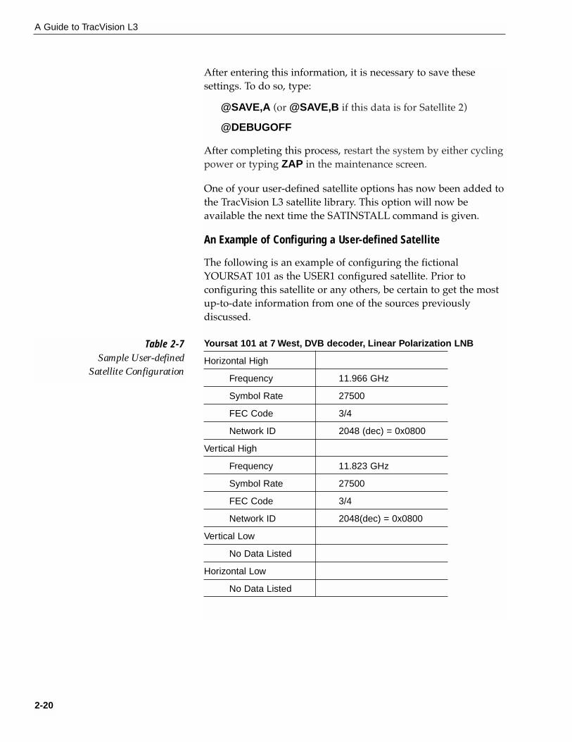
An Example of Configuring a User-defined Satellite
The following is an example of configuring the fictionalYOURSAT 101 as the USER1 configured satellite. Prior toconfiguring this satellite or any others, be certain to get the mostup-to-date information from one of the sources previouslydiscussed.
Yoursat 101 at 7 West, DVB decoder, Linear Polarization LNB
Horizontal High
Frequency 11.966 GHz
Symbol Rate 27500
FEC Code 3/4
Network ID 2048 (dec) = 0x0800
Vertical High
Frequency 11.823 GHz
Symbol Rate 27500
FEC Code 3/4
Network ID 2048(dec) = 0x0800
Vertical Low
No Data Listed
Horizontal Low
No Data Listed
2-20
A Guide to TracVision L3
Table 2-7Sample User-defined
Satellite Configuration

Based on this information, the data entered via the PC wouldlook like this, assuming that YOURSAT 101 would be Satellite A:
SATCONFIG,USER1,7,W,3,L
@DEBUGON
@SATCONFIG,A,98,11966,27500,34,0x0800,H,H,3
@SATCONFIG,A,98,11823,27500,34,0x0800,V,H,3
@SATCONFIG,A,98,00000,27500,34,0x0000,V,L,3
@SATCONFIG,A,98,00000,27500,34,0x0000,H,L,3
@SAVE,A
@DEBUGOFF
ZAP
2.5 Setting the Skew Angle(European Systems Only)
The Antenna LNB skew angle must be adjusted to optimizechannel reception. Refer to your satellite service provider for theproper skew angle for the selected satellite service andgeographical location. The skew angle for KVH predefinedsatellites can also be obtained by using a PC connected to themaintenance port. Enter your latitude and longitude using theGPS command (refer to Appendix F.6 for details) and then typeSKEWANGLE. The system will respond with the skew angle forwhichever satellite is currently selected.
Adjusting the LNB Skew Angle
1. Determine the skew angle for the selected satelliteand region.
2. Loosen the wing nut on the LNB clamp so that theLNB can be moved.
3. Carefully rotate the LNB so that the scribe markon the LNB clamp is aligned with the proper anglemeasurement.
4. Tighten the wing nut and LNB clamp to secure the LNB.
2-21
Installation
54-0157 Rev. C
Skew Angles
LNB Clamp & Wing Nut
ScribeMark
LNB
Figure 2-22Skew Adjustment (EuropeanSystems Only)

2.6 Checking Out the SystemTo complete the TracVision L3 installation, it will be necessary toverify that the system functions properly. Critical to ensuring thatthe system is configured and operating properly is to check thesystem startup routine to ensure that the system is operatingwithin normal parameters.
To do so, it is necessary to connect a PC to the terminalmaintenance port. The diagnostics procedure requires terminalemulation software such as PROCOMM, Windows Terminal, orWindows 95/98 Hyperterminal. Use the settings appropriate toyour application.
1. Connect one end of the PC data cable to the DB9connector on the switchplate. Connect the otherend to the serial port on the PC (a 9-pin/25-pinconnector adapter may be needed for some PCs).
2. Open the terminal emulation software andestablish the following settings:
• 9600 baud
• no parity
• 8 data bits
• 1 start bit
• 1 stop bit
• no flow control
3. Apply power to the TracVision L3 system andallow the system to complete full initialization.Data should be scrolling on the PC display toidentify any system problems detected. If no datais seen, recheck your connections and the terminalsoftware setup.
4. After completing the review of the startup andoperational routines, shut down the system.
Additional European System Checks
1. If the system is working properly based on thestartup information, refer to your regional satelliteprogramming guide. Select several channels fromyour first active satellite service to confirm that the
2-22
A Guide to TracVision L3

system is receiving and decoding the signalsproperly. If possible, view both horizontally andvertically polarized channels.
2. Select several channels from your second activesatellite service to confirm that the system isreceiving and decoding the signals properly. Ifpossible, view both horizontally and verticallypolarized channels.
Completing the Installation
Once the system has been installed and is operating properly,replace the radome.
2.7 Configuring TracVision L3 forRemote Satellite Dish Operation
In some campground locations, dense foliage will block thesatellite signal. In these situations, a remote portable antennamay be the only solution to satellite signal reception.
The wiring option for the remote dish is very simple and shouldbe installed when the TracVision L3 is installed. A high-quality“A/B switch” should be used to change from TracVision L3 dish reception to remote antenna operation. The recommendedwiring arrangement for remote dish operation is illustrated inFigure 2-23.
2-23
Owner’s Manual and Installation/Service Guide
54-0157 Rev. C
If a need does arise to paint theradome, ONLY use non-metallicautomotive paint to avoiddegrading the RF signal strengthand the reception quality.
IRD
A/B Switch
A B
A B
Common
TV Out
SAT in
Antenna
Remote Dish
RF Cable
RF CableRF Cable
Figure 2-23Remote Dish Wiring Configuration


3 Using Your TracVision L3For TracVision L3 to receive the satellite signals, the antennamust have a clear line of sight to the satellite. If you only receiveintermittent signals or the antenna cannot find the satellite, checkaround your vehicle for any objects that could be blocking thesignal, such as trees, buildings, highway overpasses, etc.
3.1 Turning on the SystemThe TracVision L3 system is easy to use. Antenna unitinitialization and satellite acquisition is completely automatic.
To use the TracVision L3 system:
1. Turn on the IRD and the television. (Refer to yourIRD user manual for complete operatinginstructions for the IRD.)
2. Turn on the antenna using the switchplate, aspictured in Figure 3-2.
3. Avoid turning for 60 seconds after turning on theantenna to allow the antenna gyro to initializeproperly.
3-1
Using Your TracVision L3
54-0157 Rev. C
To minimize the time it takes theantenna to acquire the satellite, donot change the channel during thestartup process or cable unwrap.
Figure 3-1Be Aware of Objects that MightBlock the Satellite Signals
Antenna�
On/Off�
Switch
Figure 3-2Turning on the TracVision L3Using the Switchplate

3.2 Changing Channels andSwitching to the SecondSatellite
TracVision L3 can have a pair of satellites installed, either one of which can be the active satellite selection. There are severalmethods to select whether your TracVision L3 will track Satellite A or B.
IRD Remote Control
If you have followed the installation instructions, your systemshould be set to the active satellite pair of your choice and thesystem should have downloaded the appropriate channel guides.You must also have a properly configured IRD (if this has notbeen done, refer to your IRD User’s Manual for instructions foryour specific IRD). When the TracVision L3 system and the IRDhave matching configurations, switching from one satellite to theother is as easy as changing the channel using the remote control.TracVision L3 will automatically switch from Satellite A to B andback again as necessary to receive your selected channel.
Maintenance Port Switch
As described in Section 2.4, “Selecting the Active Satellite,” themaintenance port can also be used to tell the Antenna Unit whichsatellite it should acquire and track. To make the antenna trackeither Satellite A or B, first connect the PC to the maintenanceport as described in Section 2.4. Once the data connection ismade, enter the Satellite Selection parser command as follows:
Command: @L,x<cr>
Where: x = A or B (one of your selected satellites as defined during the SATINSTALL process)
Choosing A or B will assign the antenna to acquire and track thatinstalled satellite.
DIRECTV Satellite Subscribers
DIRECTV subscribers in certain regions of the United States willrequire a DSS Plus™ IRD to receive both satellite and localchannels. Check with DIRECTV for regional requirements. TheDSS Plus IRD allows you to switch channels using the remote
3-2
A Guide to TracVision L3
The satellite configuration onyour IRD must match the satellitesetting on the TracVision L3system.
Satellite A on the TracVision L3must be the same satellite as IRDAlternative 1 (or A, based on yourIRD) and must be assigned the IRDDiSEqC 1 setting.
Satellite B on the TracVision L3must be the same satellite as IRDAlternative 2 (or B, based on yourIRD) and must be assigned the IRDDiSEqC 2 setting.
Refer to your IRD user manual forcomplete instructions for your IRD.
* DiSEqC applies to European systems only

control. If you are a DIRECTV subscriber, but do not have a DSSPlus IRD, use the maintenance port switching option previouslydescribed.
EchoStar and ExpressVu Satellite Subscribers
EchoStar and ExpressVu subscribers will need to use themaintenance port switching method.
3.3 Watching TV on the Move and at Rest
TracVision L3 is designed to operate as efficiently and as reliablyas possible both when your vehicle is in motion and parked.
Using Your TracVision L3 When Parked
When your vehicle is stopped, it is not necessary for theTracVision L3 to be turned on. After parking your vehicle andconfirming that the antenna is receiving the satellite signal, youmay turn off the TracVision L3 unit to avoid unnecessary use ofpower. Because the LNB receives its power from the IRD, theantenna will continue to receive the satellite TV signals and relaythem to the IRD.
However, if you plan to change to a channel that is broadcast byanother satellite, TracVision L3 must be turned on so the antennacan search for, identify, and lock onto the different satellite.
Cable Unwrap
The Antenna Unit can rotate a full 720° before coming to the endof its cable. If it does so, the system automatically unwraps thecable by quickly rotating the dish in the opposite direction.During this process, your television transmission will be frozenmomentarily while the cable unwraps and the antenna reacquires the satellite.
Sleep Mode
When the vehicle has come to a stop and the antenna holds itsposition for 1 minute, the Antenna Unit enters Sleep Mode,which turns off the conical scan tracking, reducing any motornoise the antenna may be making. As soon as the vehicle moves,Sleep Mode will automatically be turned off and the system will
3-3
Using Your TracVision L3
54-0157 Rev. C
Unlike turning the power off, theantenna will still be operational anddrawing power when in SleepMode. If you are going to be parkedfor an extended period of time,turning off the antenna willconserve power while still allowingyou to receive the TV signals.

begin tracking the satellite again. This convenient feature is idealfor when a vehicle is parked for a short time or idling andpassengers want to watch TV.
KVH recognizes that some customers may not want to takeadvantage of this convenient feature. In this case, it is possible todisable Sleep Mode using a simple software command as follows:
1. Connect a laptop computer to the system used themaintenance port and a terminal emulationprogram, as described in Section 2.4.1, InstallingYour Selected Satellites.
2. Turn on the antenna. When the limit switch test iscomplete:
A. Type HALT<cr> (<cr> indicates a carriagereturn/ENTER key)
B. Type DEBUGON<cr>
C. Type SLEEPOFF<cr>
3. Cycle the antenna’s power. Sleep Mode is nowdisabled.
4. To reactivate Sleep Mode, follow this sameprocess, instead using SLEEPON<cr> in Step C.
Conical Scan Tracking
The antenna control unit uses conical scanning to maintain peaksignal strength to the receiver and to update the satellite’sposition. When conical scan tracking is active, the antenna movescontinually with a circular motion to sweep across the satellite’speak signal. The signal strength is then fed back to the controlcircuits to keep coming back to the direction of the strongestsignal.
If the satellite signal is lost while the system is in conical scantrack mode, the control software imposes a 45-second time-outdelay. If the signal is not regained during that time, the antennareverts to the set of Search Modes to start looking for the satellitesignal. This is an automatic process that does not require userintervention.
3-4
A Guide to TracVision L3

4 TroubleshootingThe troubleshooting matrix shown in Table 4-1 identifies sometrouble symptoms, their possible causes, and references totroubleshooting solutions.
4.1 Causes and Remedies forCommon Operational Issues
There are a number of common issues that can affect the signalreception quality or the operation of the TracVision L3. Thefollowing sections address these issues and potential solutions.
4-1
Troubleshooting
54-0157 Rev. C
Table 4-1Troubleshooting Matrix
Antenna non-functional X
Antenna not switching channels/satellites X
No picture on TV set X X X X X
Intermittent picture for short intervals X X X X X X X X X
System works at rest but not on the move X X
System will not find satellite X X X X X X X
Snowy television picture X
Picture jumbled, parts missing, freezing X
Outsidesatellite
coveragezone(Section4.1.5)
IRDwiring(Section4.2.1)
Antennagyrofaulty
(Section4.3)
LNBassemblyfaulty
(Section4.3)
IRDfaulty
(Section4.2.2)
Satellite
signal blocked(Section4.1.3)
Incorrectorloose
RFconnectors
(Section4.1.7)
PO
SS
IBLE
CA
US
E (A
ND
SO
LUTI
ON
)
SYMPTOM Vehicleturningduringstartup(Section4.1.6)
Deworrainpoolingondome(Section4.1.4)
Blownfuse
orimproperwiring(Section4.1.1)
Incorrectsatellite
configuration(Section4.1.2)
Passivemultisw
itchused(Section4.1.8)

4.1.1 Blown Fuse or Improper WiringIf the Antenna Unit is installed but entirely non-responsive, thereare three key factors to check as part of the troubleshootingprocess:
1. Blown Fuse – The Antenna Unit is equipped witha fuse mounted on its CPU Board. If this fuse hasblown or been broken, the Antenna Unit will notoperate. Refer to Section 5.4.1, “PCB Removal andReplacement,” for details on the fuse location andhow to access the CPU Board.
2. Wiring – If the system has been improperly wired,the Antenna Unit will not operate correctly. Referto Section 2.3, “Wiring the TracVision L3 System,” forcomplete system wiring information.
4.1.2 Incorrect Satellite ConfigurationThe satellite configuration on your IRD must match the satellitesetting on the TracVision L3 system.
• Satellite A on the TracVision L3 must be the samesatellite as IRD Alternative 1 (or A, based on yourIRD) and must be assigned the IRD DiSEqC 1setting.*
• Satellite B on the TracVision L3 must be the samesatellite as IRD Alternative 2 (or B, based on yourIRD) and must be assigned the IRD DiSEqC 2setting.*
* The DiSEqC settings only apply to European systems.
Refer to your IRD user manual for complete instructions onconfiguring your IRD.
4.1.3 Satellite Signal BlockedSatellite signals can be blocked or degraded by trees andbranches, buildings, mountains, overpasses, or equipment on thevehicle itself. Refer to Section 2.1, “Choosing the Best Location,” tomake certain that the TracVision L3 unit is in the optimallocation. Simply moving the vehicle to clear an externalobstruction will also restore signal quality.
4-2
A Guide to TracVision L3

4.1.4 Dew or Rain Pooling on DomeDew or rain can occasionally pool on the top of the radome.While this moisture will usually be dispersed when the vehicle isin motion, it can disrupt the signal while the vehicle is at rest.This issue can be minimized with two approaches:
1. Spray the dome with hosed water to remove thedew from the dome surface.
2. Periodically apply liquid dish detergent to thedome surface. Wipe the full-strength detergent onthe dome and allow it to dry. This treatment willprovide a film that will help moisture bead up androll off the dome.
4.1.5 Outside Satellite Coverage ZoneTracVision L3 will provide outstanding reception throughout theentire coverage area for your satellite television service of choice.However, signal quality can be degraded as you approach thefringe coverage areas. Refer to your satellite television servicemanual to check the viable coverage area.
4.1.6 Vehicle Turning During StartupIf the vehicle turns during the 60-second startup andinitialization sequence that occurs immediately after turningon the power to the TracVision L3 unit, the antenna gyro willrecord that variable motion as “standing still.” This may causethe antenna to track improperly. To solve this problem, turnTracVision L3 off for at least 10 seconds. Turn the system backon, making certain that the vehicle is either motionless ortravelling in a straight line for the 60 seconds immediatelyfollowing power-up.
4.1.7 Incorrect or Loose RF ConnectorsAs part of preventive maintenance (described in Section 5,“Maintenance,”) KVH recommends checking the Antenna Unitcable connections. A loose RF connector can reduce the signalquality. Refer to Section 2.3.6, “Connecting the Antenna RF SignalCable to the IRD” for directions on proper Antenna Unit to RF cabling.
4-3
Troubleshooting
54-0157 Rev. C
Baseline RF levels are included aspart of the startup sequenceprovided in Appendix E.

4.1.8 Using a Passive Multiswitch(North American Systems Only)
An active multiswitch must always be used to connect theTracVision L3 system to multiple IRDs. Refer to Section 2.3.6,“Connecting the Antenna RF Signal Cable to the IRD” fordirections on proper multiswitch/multiple IRD cabling.
4.2 IRD TroubleshootingThe IRD that was provided with your satellite television servicemay also be the cause of less-than-ideal operation.
4.2.1 IRD WiringRefer to Section 2.3.6, “Connecting the Antenna RF Signal Cable tothe IRD” and your IRD user manual to confirm that the IRD isproperly connected to the Antenna Unit and the television.
4.2.2 IRD FaultyIn the case of a faulty IRD, refer to your IRD user manual forservice, replacement, and warranty information.
4.3 Antenna Gyro and LNB FaultsSection 5, “Maintenance,” provides detailed instructions forauthorized service personnel who may be required to replace theTracVision L3 antenna gyro or the LNB.
4.4 Computer DiagnosticsTracVision L3 has been designed to provide diagnostic readoutsviewed on the TV screen (DIRECTV only) or on a personalcomputer having an RS-232 serial communication port. If you areunable to isolate a system problem with the foregoingtroubleshooting tools, set up a laptop to carry out computerdiagnostics as described on the next page. System problems willmost likely be found somewhere through the diagnostic readouts.
4-4
A Guide to TracVision L3

The diagnostics procedure requires terminal emulation softwaresuch as PROCOMM, Windows Terminal, or Windows 95/98Hyperterminal. Use the settings appropriate to your application.
1. Connect one end of the PC data cable to the DB9connector on the switchplate. Connect the otherend to the serial port on the PC (a 9-pin/25-pinconnector adapter may be needed for some PCs).
2. Open the terminal emulation software andestablish the following settings:
• 9600 baud
• no parity
• 8 data bits
• 1 start bit
• 1 stop bit
• no flow control
3. Apply power to the TracVision L3 system andallow the system to complete full initialization.Data should be scrolling on the PC display toidentify any system problems detected. If no datais seen, recheck your connections and the terminalsoftware setup.
4.5 Maintenance Port ParserCommands
TracVision L3 system parser commands are detailed in Appendix F.
4-5
Troubleshooting
54-0157 Rev. C


5-1
Maintenance
54-0157 Rev. C
5 Maintenance5.1 Warranty/Service InformationKVH Industries, Inc. warrants the KVH product purchasedagainst defects in materials for a period of TWO (2) years andagainst labor costs for a period of ONE (1) year from the date oforiginal retail purchase by the original purchaser. It is thecustomer’s responsibility to verify the date of purchase byreturning the warranty card included with the product to KVHwithin 30 days of purchase, or by providing a copy of a datedsales receipt for the KVH product under warranty with thewarranty claim. If this date cannot be verified, the warrantyperiod will begin 30 days after the date of manufacture of theoriginal product purchased.
For additional information on KVH warranty, repair, and liabilitypolicies, please refer to the warranty statement provided withyour TracVision L3.
5.2 Preventive MaintenanceTracVision L3 requires minimal preventive maintenance. Thefollowing tasks are sufficient to maintain peak performance.
Monthly
• Wash the exterior of the radome and baseplateassembly with fresh water; a mild detergent maybe added to remove grime. Do not spray theradome directly with high-pressure water.
• Do not apply abrasive cleaners or volatile solventssuch as acetone to the ABS radome.
Annually
• Remove the radome and examine the interior ofthe Antenna Unit for signs of corrosion, looseconnections, or frayed or broken wires.
• Clean and wax the radome.
• Visually inspect the elevation drive shaft to becertain that it moves easily and is clear of grit anddebris. Clean and lubricate as required.
The serial number of yourTracVision L3 will be requiredduring any troubleshooting orservice calls. You will find the serial number on the warranty cardaccompanying your system as wellas in front of the antenna reflectoron the rotating plate.

5-2
A Guide to TracVision L3
5.3 Replaceable PartsTracVision L3 has been designed with durability and lowmaintenance in mind. If you experience an operating problem orotherwise require technical assistance, contact your localauthorized TracVision L3 dealer/distributor first. Have theAntenna Unit serial number ready with a list of the troublesymptoms. If an authorized dealer/distributor is not locatednearby, contact the factory directly at the telephone, facsimile, ore-mail listings inside the front cover.
Replacement part numbers for units that can be serviced in thefield are listed in Table 5-1. These parts may be obtained fromany KVH authorized dealer/distributor.
Part Name Part Number
Baseplate Assembly 02-1044-01
Radome Assembly 02-0953-03
Power Cable 32-0590-30
Antenna Data Cable 32-0630-30
RF Cable 32-0589-30
PC Cable 32-0628-06
CPU PCB 02-1043-02
RF PCB 02-1017-02
Antenna Gyro 02-1035
Antenna Gyro Gasket 24-0139
System Fuse 16-0017-4000
LNB (European System) 19-0196
LNB (N. American System) 19-0056
Switchplate 02-1023
It is recommended that all other technical difficulties be resolvedby returning the TracVision L3 unit to an authorized serviceprovider.
Table 5-1Field Replaceable Units
Should the fuse ever need to bereplaced, TracVision L3 uses a 5x20mm, 4-amp, 250-volt fast-blow fuse.
To help us continually improve thequality and reliability of oursystems, please return any failedcomponent to KVH or KVH Europeafter you receive your replacementpart.

5-3
Maintenance
54-0157 Rev. C
5.4 Field Replaceable UnitProcedures
The following subsections provide detailed procedures forrepairing or swapping out field replaceable units. The proceduresrefer to labeled items presented on the following isometricdiagrams, which are based on KVH assembly drawings.
PCB
PCB Cover
Pan Head Screws
Rotating Plate
RF Board
Standoffs
RF Board Cover
RF CoverScrews
Pivot Bracket
Elevation Axis �
Motor Shaft
Linear Actuator
Quick Release Pin
Figure 5-2Close-up of Linear Actuator, Pivot Bracket, and Pin
Always lift the Antenna Unit bythe gray baseplate, never by theradome or any portion of theantenna assembly!
Figure 5-1Antenna, PCB, and Rotating Plate

5-4
A Guide to TracVision L3
Figure 5-3Antenna Assembly
Locking Nuts�
and Washers
Antenna Gyro
Antenna Gyro Cable
Reflector Bracket
Wing Screw�
and Washer
LNB Clamp
European
Antenna Gyro
Gasket
N. American
LNB Styles
Antenna Reflector
PCB
Cable Clamp
RF Board
Cable Clamp Screw
Rotating Plate
AntennaGyro Cable
Figure 5-4Close-up of RF Detector and PCB

5-5
Maintenance
54-0157 Rev. C
5.4.1 PCB Removal and ReplacementEstimated Time to Repair: 1⁄2 hour
The microprocessor PCB assembly is protected by a coverfastened to the rotating plate – Fig. 5-1. The cover must beremoved to gain access to the main power fuse and the PCBassembly.
1. Remove the quick release pin from the pivotbracket – Fig. 5-2.
2. Remove the elevation axis motor shaft from thelinear actuator – Fig. 5-2.
3. Remove the 6 pan head screws from the PCB coverflanges. Remove the PCB cover – Fig. 5-1.
4. Remove cable connectors from PCB. Figure 5-5illustrates the PCB arrangement and connectorlocations.
5. The PCB is mounted to the rotating plate with 9 pan head screws. Remove the screws and PCB.
6. Reverse this process to install the replacementPCB. Reinstall all cable connectors removed inStep 4.
7. Carry out all calibration procedures for theantenna gyro (Section 5.4.3).
8. Reinstall your preferred satellites as detailed inSection 2.4.1, Installing Your Selected Satellites.
RF Board
PCB
J3 J1
RF Connector to IRD
RF Connector to LNB
Fuse
J5
J11
J9J2 J1
J4
Gyro
RF Board
Limit Switches
Cable Wrap
Elevation Motor Azimuth Motor
TracVision L3 is equipped with a5x220 mm, 4-amp, 250 volt fast-blow fuse, which is mounted on thePCB. To access and replace thefuse, follow the directions to removethe PCB cover and then swap theblown fuse for a new one.
When carrying out maintenance on the PCB, be sure to not dropany of the small screws inside themechanism. If a screw is lost withinthe baseplate, it must be retrievedto avoid causing any damage whenthe unit rotates.
Figure 5-5PCB and RF Detector BoardConnector Locations

5-6
A Guide to TracVision L3
5.4.2 RF Detector/DVB DecoderEstimated Time to Repair: 1⁄2 hour
The RF Detector PCB receives operating voltages from both theCPU board and the IRD (via the RF cable) – Fig. 5-1. Ensure thatall power is turned off before proceeding.
1. Remove the 4 RF board cover screws and washersfrom the RF board cover.
2. Remove the RF board cover.
3. Remove 2 RF connectors from the coaxial fittingson the PCB. Tag the cables to ensure that they arereturned to the same connectors.
4. Remove the Molex connectors from J3 and J1 – Fig. 5-5.
5. Remove the 4 standoffs – Fig. 5-1. Remove the RFDetector PCB from the rotating plate.
6. Installation of the replacement RF Detector is thereverse of this procedure. Be sure that the RFcables are restored to their original positions. Besure that the center conductor pin is centered inthe connector before tightening the collar.
5.4.3 Antenna Gyro AssemblyEstimated Time to Repair: 1 hour
The antenna gyro is mounted on the rear of the antenna reflectorbracket with four locking nuts and washers – Fig. 5-3. Followingthe removal and replacement of the antenna gyro assembly, itwill be necessary to calibrate the gyro and restart the system.Directions for removal, replacement, and calibration follow:
1. Remove the quick release pin from the pivotbracket – Fig. 5-2.
2. Remove the elevation axis motor shaft from thelinear actuator – Fig. 5-2.
3. Remove the 6 pan head screws from the PCB coverflanges. Remove the PCB cover – Fig. 5-1.
4. Remove the screw and clamp holding the antennagyro cable to the rotating plate. Be sure to save thecable clamp and screw – Fig. 5-4.
Following the removal andreplacement of the antenna gyroassembly, it will be necessary tocalibrate the gyro and restart the system.

5-7
Maintenance
54-0157 Rev. C
5. Remove the Molex connector from J11 on the CPUboard – Fig. 5-5.
6. Remove the 4 nuts and washers and take the gyrooff of the bracket.
7. Remove the antenna gyro gasket.
8. Replacement is the reverse of this procedure.
Antenna Gyro Calibration
1. Connect a PC to the communications port asdescribed in Section 4.4, “Computer Diagnostics.”
2. Type HALT<cr> while the system is performingthe limit switch initialization routine. The systemwill complete the initialization function by findingthe azimuth and elevation switch limits and thengo to the home position.
3. Type DEBUGON<cr> to enter Debug Mode.
4. Type =CALGYRO<cr>. Verify that the AntennaGyro Azimuth scale factor is between -0.00090 and-0.00110 and the Antenna Gyro Elevation scalefactor is between 0.00090 and 0.00110.
5. Type ZAP to restart/reinitialize the system.
5.4.4 Antenna LNB ReplacementEstimated Time to Repair: 1⁄2 hour
In the event that the LNB experiences problems, it may benecessary to replace it. To do so, use the following procedure:
1. Make a note of the current LNB skew angle,pictured in Figure 5-6 (European systems only).
2. Disconnect the RF cable connector at the LNB.
3. Remove the wing nut and washer from the LNBclamp – Fig. 5-3.
4. Remove the top of the LNB clamp and remove theLNB.
5. Place the new LNB in the clamp and reattach theRF connector.
The LNB receives power from theIRD via the RF Detector PCB. Becertain that the IRD is disconnectedfrom its power source beforeremoving or reconnecting the LNB.
Skew Angles
LNB Clamp & Wing Nut
ScribeMark
LNB
Figure 5-6LNB Skew Angle Setting(European Systems Only)

5-8
A Guide to TracVision L3
6. Replace the LNB clamp:
A. For North American LNBs, tighten the clampfully. The replacement process is complete.
B. For European LNBs, do not fully tighten theclamp and proceed to step 7.
7. Carefully turn the LNB so that the scribe mark isaligned with the skew angle noted in Step 1. Fullytighten the clamp to complete the replacementprocess.
5.5 Preparation for ShipmentIf it is necessary to repack the Antenna Unit for shipment, theshipping restraints removed during installation must be replaced.Follow these steps to reinstall the restraints.
1. Remove the Antenna Unit from the mountingplate.
2. Rotate the Antenna Unit so that the LNB is facingforward (away from the liquid-tight fittings).
3. Wedge the three baseplate restraints between therotating plate and the edge of the baseplate aspictured in Figure 5-7.
4. Wrap the elevation restraint around the elevationaxis motor shaft as shown in Figure 5-8.
Figure 5-8Placing the Elevation Axis
Shaft Restraint
When rotating the azimuthmechanism by hand, go slowly!Hitting the mechanical stops withexcessive force will damage theazimuth limit switch.
Figure 5-7Attaching the Shipping Restraints
to the Antenna Baseplate

5. Secure the elevation restraint by wrapping two tie-wraps through the open end of the restraint asshown in Figure 5-9.
6. Place the entire Antenna Unit into its shippingcontaining using the original packaging material,as illustrated in Figure 5-10.
5-9
Maintenance
54-0157 Rev. C
Figure 5-9Securing the Elevation Axis Shaft Restraint
Foam Inserts
Base Support
Shipping Box
Figure 5-10Repackaging the TracVision L3


Appendix ASystem SpecificationsPhysical Characteristics
Power 11-16 volts DC @ 2.5 amps nominal,3.5 amps peak
Dimensions/Weight 32" (81 cm) wide x 14.5" (37 cm) high,33 lbs (15 kg)
LNB European System: Single OutputN. American System: Dual Output
Tracking Better than 30˚/sec
Maintenance Port 9600 bps, 8,N,1,EIA, RS232
Pointing System
Elevation Range 15˚ to 75˚
Azimuth Range 720˚
Position Repeatability 0.1˚
Environmental
Operating Temperature -25˚C to +55˚C
Storage Temperature -40˚C to +85˚C
Humidity to 100 percent
Table A-1TracVision L3 SystemSpecifications
A-1
System Specifications
54-0157 Rev. C

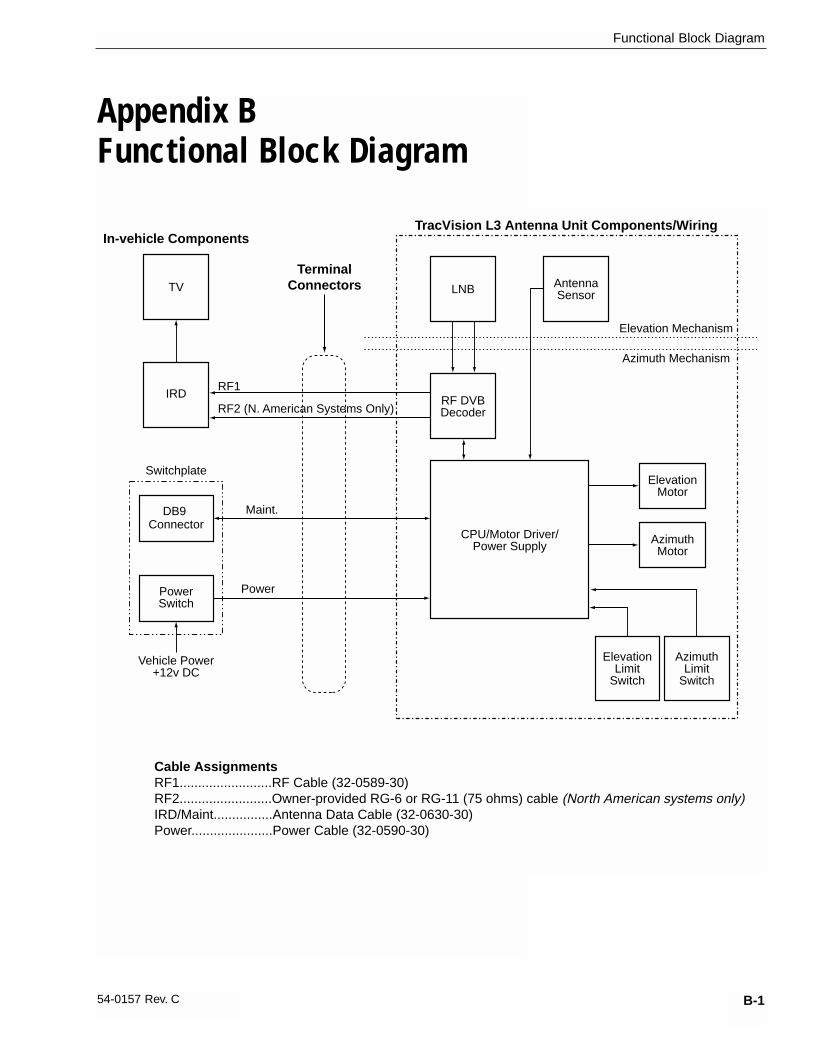
Appendix BFunctional Block Diagram
B-1
Functional Block Diagram
54-0157 Rev. C
ElevationMotor
AzimuthMotor
TV
IRD
Elevation Mechanism
Azimuth Mechanism
AntennaSensor
AzimuthLimit
Switch
RF1
Maint.
Power
TracVision L3 Antenna Unit Components/WiringIn-vehicle Components
TerminalConnectors
Cable AssignmentsRF1.........................RF Cable (32-0589-30)RF2.........................Owner-provided RG-6 or RG-11 (75 ohms) cable (North American systems only)IRD/Maint................Antenna Data Cable (32-0630-30)Power......................Power Cable (32-0590-30)
ElevationLimit
Switch
CPU/Motor Driver/Power Supply
DB9 Connector
Vehicle Power+12v DC
PowerSwitch
Switchplate
RF2 (N. American Systems Only)RF DVBDecoder
LNB


Appendix CSw
itchplate Template
C-1
Sw
itchplate Template
54-0157 Rev.C
3.82"(97 mm)
.32" (8 mm)
2.36"(60 mm)
.16" (4 mm)3.19"
(81 mm)
2.05"(52 mm)
Panel Cutout
3/32" (3 mm) dia


Appendix DPredefined SatelliteConfigurationsAs noted previously, your TracVision L3 comes programmedwith the satellite configurations for seven European and eightNorth American satellite services. For your reference, thoseconfigurations are listed below. These configurations are currentas of September 15, 2000, and are subject to change by thesatellite service providers.
European Satellites
Satellite F,S,C,ID,P,B,D
Astra 1 11778,27500,34,0x0020,V,H,311742,27500,34,0x0020,V,L,312344,27500,34,0x0035,H,H,311876,27500,34,0x0020,H,L,3
Astra 2N 11778,27500,23,0x0020,V,H,300000,27500,34,0x0000,V,L,311914,27500,23,0x0020,H,H,300000,27500,34,0x0000,H,L,3
Astra 2S 11972,27500,23,0x0020,V,H,300000,27500,34,0x0000,V,L,312226,27500,23,0x0020,H,H,300000,27500,34,0x0000,H,L,3
Hispasat 12152,27500,34,0x0031,V,H,311660,27500,34,0x0031,V,L,312154,27500,34,0x0031,H,H,311522,27500,34,0x0031,H,L,3
Hotbird 12073,27500,34,0x0013,V,H,311958,27500,34,0x0013,V,L,311862,27500,34,0x0013,H,H,311862,27500,34,0x0013,H,L,3
Sirius 12130,27500,34,0x03E8,V,H,300000,27500,34,0x0000,V,L,312108,27500,34,0x0001,H,H,300000,27500,34,0x0000,H,L,3
Thor 12226,2800,78,0x0046,V,H,311309,24500,78,0x0046,V,L,312322,27800,34,0x0046,H,H,311229,24500,78,0x0046,H,L,3
D-1
Predefined Satellite Configurations
54-0157 Rev. C
Configuration Definitions
F = Frequency
S = Transponder symbol rate
C = FEC code
ID = Satellite network ID
P = LNB polarization (vertical orhorizontal)
B = LNB Band (high, low, or USA)
D = Decoding type (3 = DVB)

North American Satellites
Satellite F,S,C,ID,P,B,D
ExpressView 12603,20000,56,0X0100,V,U,312603,20000,56,0X0100,V,U,312384,20000,56,0X0100,H,U,312384,20000,56,0X0100,H,U,3
Echostar 61 12577,20000,34,0X1002,V,U,312577,20000,34,0X1002,V,U,312358,20000,34,0X1002,H,U,312358,20000,34,0X1002,H,U,3
Echostar 110 12456,20000,34,0X1006,V,U,312456,20000,34,0X1006,V,U,312383,20000,34,0X1006,H,U,312383,20000,34,0X1006,H,U,3
Echostar 119 12374,20000,34,0X1004,V,U,312374,20000,34,0X1004,V,U,312381,20000,34,0X1004,H,U,312381,20000,34,0X1004,H,U,3
Echostar 148 00000,20000,34,0X1004,V,H,300000,20000,34,0X1004,V,U,300000,20000,34,0X1004,H,H,300000,20000,34,0X1004,H,U,3
DIRECTV 101 12368,20000,67,0X0000,V,U,212368,20000,67,0X0000,V,U,212238,20000,67,0X0000,H,U,212238,20000,67,0X0000,H,U,2
DIRECTV 110 12456,20000,34,0X1006,V,U,312456,20000,34,0X1006,V,U,312383,20000,34,0X1006,H,U,312383,20000,34,0X1006,H,U,3
DIRECTV 119 12374,20000,34,0X1004,V,U,312374,20000,34,0X1004,V,U,312381,20000,34,0X1004,H,U,312381,20000,34,0X1004,H,U,3
D-2
A Guide to TracVision L3

Appendix EStartup Data SequenceThe data on the following pages presents a standard startup datasequence registered by the TracVision L3. This sequence can berecorded using the data port and a PC.
?PGM
KVH TracVision L3 Rev X - Version X.XX - Serial Number XXXXXXXX
RF: ZAP
*** Initializing RF Controller ***
RF: S,A,H,U,V
RF: SATINSTALL,55,C,57,C
RF: L,B-------------------------------------------Identifies Satellite A or B as currently
RF: SATCONFIG loaded for acquisition
RF: F,A,12368,20000,67,0X0000,V,U,2---------------Satellite configuration data, Satellite A
RF: F,A,12368,20000,67,0X0000,V,U,2
RF: F,A,12238,20000,67,0X0000,H,U,2
RF: F,A,12238,20000,67,0X0000,H,U,2
RF: F,B,12374,20000,34,0X1004,V,U,3---------------Satellite configuration data, Satellite B
RF: F,B,12374,20000,34,0X1004,V,U,3
RF: F,B,12381,20000,34,0X1004,H,U,3
RF: F,B,12381,20000,34,0X1004,H,U,3
RF: RF PCB Version X.X----------------------------Current RF software revision
RF: S,B,H,U,V
RF: I,0,48960,00000,00433,0
RF COMM: PASS-------------------------------------PASS is expected
RF: S,B,H,U,V
*** Initializing Antenna ***
GPS: UTC: 083000.00, Lat: 4131.00N, Long: 7115.00W
GPS: DSS_119 AZ = 238.9, EL = 22.1
GPS: DSS_101 AZ = 220.9, EL = 33.4
Limit Switch Test
Limit Switch Status: PASS-------------------------PASS is expected
RF: S,B,H,U,V
*** Initializing Rate Bias ***
RF: S,B,V,U,V
+A/D: 1992 2033 601
RF: S,B,H,U,V
Gyro Bias: Az = 1991.95, El = 2032.05------------Expected range is 1700-2300
Gyro Uncertainty: Az = 3.00, El = 3.00
*** Limit Switch Search ***
RATE BIAS: PASS-----------------------------------PASS is expected
Searching for DSS_119, Threshold = 1000
+POS: 80.5 25.9 273
RF: S,B,H,U,V
+POS: 11.3 25.9 513
RF: S,B,V,U,V
+POS: 300.8 25.9 162
RF: S,B,V,U,V
Satellite Found: AZ = 231.1, EL = 25.9, RF = 1793
+POS: 230.4 25.9 1963
E-1
Startup Data Sequence
54-0157 Rev. C

*** Entering Tracking ***
RF: S,B,H,U,V
+POS: 231.5 26.2 1334
+POS: 231.3 25.8 2023
+POS: 230.6 24.4 2741
RF: Freeze DAC = -00652
+POS: 230.1 23.9 2829
*** Network ID Check ***---------------------Comparing the tracked satellite’s network ID to the
+POS: 230.0 23.5 2843 selected satellite’s network ID
RF: Y,0X1004---------------------------------Indicates positive satellite identification
*** Tracking DSS_119 ***---------------------Identifies satellite currently tracked
+POS: 229.0 22.6 3010 (TV broadcast image should be available)
+POS: 229.5 23.1 2935
+POS: 228.6 22.7 2940
+POS: 229.5 22.8 2881
+POS: 228.5 22.9 2835
Saved Sat Pos: AZ = 228.91, EL = 22.86
RF: AGCON
RF: AGC=51528
Gyro Bias Residue: Az = 2.5363e-01 EL = -6.1966e-01
+POS: 229.3 22.7 2520
+POS: 228.6 23.3 2516
Conscan=>sleep: sat in 1 deg window.
Sleeping
Old Gyro Bias: Az = 1991.95 EL = 2032.05
New Gyro Bias: Az = 1991.70 EL = 2032.67
E-2
A Guide to TracVision L3

Appendix FMaintenance Port Parser CommandsTracVision L3 system parser commands are parsed when thesystem receives an ASCII carriage return (Hex 0D). An ASCII linefeed (Hex 0A) is permitted but is ignored in any transmittedcommand. All system responses are terminated with an ASCIIcarriage return followed by a line feed and ending with either anacknowledge character (ASCII > (Hex 3E)) or a not-acknowledgecharacter (ASCII ? (Hex 3F)). The parser commands are shownbelow in boldface capital letters but they are not case-sensitive. Inmost cases the command is responded to with an echo; that is, ifyou type ZAP, for example, and press “ENTER” the responsewill be the command you have entered. For other commands theresponse is specific for each command, such as VERSION,STATUS or HELP.
F.1 System CommandsSoftware Version
Function: reports software version and system type
Command: VERSION
Argument: none
Response: KVH TracVision L3 Version XX.XX
System Status Report
Function: reports general system status
Command: STATUS
Argument: none
Response: system status string
Initialize the System
Function: initializes the system (perform a soft reset)
Command: ZAP
Argument: none
Response: echoes the command, then reinitializes the system
F-1
Maintenance Port Parser Commands
54-0157 Rev. C
Table F-1System Commands

Calibrate Gyro
Function: performs azimuth and elevation calibration
Command: CALGYRO
Argument: none
Response: echoes command and calibrates gyro
Find Skew Angle for Currently Selected Satellite
Function: calculates necessary LNB skew based on latitude,longitude, and selected satellite
Command: SKEWANGLE*
Argument: none
Response: displays skew angle
* Before this command can function properly, you must perform the GPSPosition command detailed in Section F.6 to provide the system with the properlatitude and longitude.
Help on Parser Commands
Function: lists parser commands
Command: HELP
Argument: none
Response: print a list of all parser commands
F.2 Manual Positioning CommandsTo execute the following commands, first put the Antenna Unit inidle mode by typing HALT and pressing “ENTER.” Positioningcommands may be entered after the antenna comes to rest.
Azimuth Angle
Function: commands a manual azimuth angle that themechanism moves to
Command: AZ,xxxx (range is 0000-3599)
Argument: desired azimuth angle of the mechanism relative toexternal magnetic reference, or baseplate fwd,000°-359.9°
Response: echoes the command; mechanism moves at a fixed velocity
F-2
A Guide to TracVision L3
Table F-2Manual Positioning Commands

Elevation Angle
Function: commands a manual elevation angle that themechanism moves to
Command: EL,xxx (range is 100-850)
Argument: desired elevation angle of the mechanism relative toup, 10.0°-85.0°
Response: echoes the command; mechanism moves at a fixed velocity
Azimuth CW Step
Function: commands a 0.1 deg CW manual step in azimuthangle
Command: 6
Argument: none
Response: echoes the command
Azimuth CCW Step
Function: commands a 0.1 deg CCW manual step in azimuthangle
Command: 4
Argument: none
Response: echoes the command
Elevation UP Step
Function: commands a 0.1 deg UP manual step in elevationangle
Command: 8
Argument: none
Response: echoes the command
Elevation DOWN Step
Function: commands a 0.1 deg DOWN manual step inelevation angle
Command: 2
Argument: none
Response: echoes the command
F-3
Maintenance Port Parser Commands
54-0157 Rev. C

F.3 Operational CommandsTo execute the following commands, first put the Antenna Unit inidle mode by typing HALT and pressing “ENTER.” After thesystem comes to a halt, type DEBUGON and press “ENTER” toenter programming mode.
Tracking Mode
Function: starts active tracking of the satellite
Command: TRACK
Argument: none
Response: echoes the command
Idle Mode
Function: halts active tracking and conical scan, then entersidle mode
Command: HALT
Argument: none
Response: echoes the command
Current Cable Wrap Angle
Function: sets or reports current cable wrap angle, defined as0° (CCW limit) to 700° (CW limit); the value isexpressed as 0000-7000 with an implied decimal
Command: WRAPANGLE,xxxx
Argument: the desired cable wrap angle setting
Response: Wrap Angle = xxxx
F.4 Tracking and Conical Scan Commands
Target Location
Function: reports the target location in antenna frame. Dataformat is E### for elevation in degrees 000-900 andA#### for azimuth in degrees 0000-3599 withimplied decimals
Command: TGTLOCATION
Argument: none
Response: Target Location = A = E###, A####B = E###, A####
F-4
A Guide to TracVision L3
Table F-4Tracking and Conical
Scan Commands
Table F-3Operational Commands

Analog Signal Strength Report
Function: reports signal strength from RF detector circuit inA/D counts (000-FFF Hex)
Command: SIGLEVEL
Argument: none
Response: Signal Strength = xxxx
F.5 RF Board CommandsSerial Communications, Status/Polarization Report, Tone Changes
Function: start serial communications, reports status &polarization/tone changes
Command: @S
Response: S,s,p,b,m <cr> every 5 seconds until ><cr>isreturned from system software
Where: s = Satellite (a = Primary, b = Secondary)p = Polarization (v = Vertical, h = Horizontal, x = NoLNB Power)b = Band (h = High Band, l = Low band, u = USA)m = Mode (v = Valid, i = Invalid)*
* The Mode bit is used to evaluate the Satellite, Polarization, & Bandcombination vs. the Frequency/Symbol Rate/FEC currently in RAM. This bit willbe set to invalid if the Frequency for the selected combination is set to 0x0000;otherwise it will be set to valid.
Report RF Tracking Parameters
Function: reports all RF tracking parameters for primary &secondary satellites*
Command: @SATCONFIG
Response: F,x,fffff,S,C,ID,P,B,D <cr>
Where: x = Satellite (a = Primary, b = Secondary)fffff = Frequency in MHz (00000 and 10700 to
12700)S = Symbol rate in Mbit/Sec (1000 to 29999)C = FEC code rate (valid rates = 12, 23, 34, 56,
67, 78)ID = Satellite Network ID in hexidecimal format
(valid range = 0x0000 to 0xffff hex)P = LNB Polarization (v = Vertical, h = Horizontal)B = the LNB down conversion frequency (l = low,
h = high, u=USA)D = decoding type (0 = test, 1 = DSS-A, 2 = DSS-B,
3 = DVB)
* This command dumps all eight combinations of the Satellite/Freq/Sym/FEC/ID/POL/Band/Decode currently stored in RAM.
F-5
Maintenance Port Parser Commands
54-0157 Rev. C
Table F-5RF Board Commands

Set RF Tracking Parameters
Function: sets RF tracking parameter
Command: @SATCONFIG,X,N,F,S,C,ID,P,B,D<cr>
Response: Echoes the input data
Where: @SATCONFIG = directs data to the RF Board
X = satellite location A or B
N = satellite table # (98 & 99 are slots for user-configured satellites)
F = frequency in MHz (either 00000 or a range from10700 - 12700)
S = the satellite transponder symbol rate inMbit/second (01000 - 29999)
C = the FEC code (e.g., 12, 23, 34, 56, 67, 78)
ID = the satellite network ID in hexidecimal format(0x####)
P = the LNB polarization (v=vertical, h=horizontal)
B = the LNB down conversion frequency (l=low,h=high, u=US)
D = decoding type (0=test, 1=DSS-A, 2=DSS-B,3=DVB)
ID Match/Decoded Network ID
Function: report ID match and decoded network ID
Command: @CHECKID
Response: Y,0X####N,0X####Y,NoIDN,NoID
Where: Y = yesN = no0X#### = network IDNoID = satellite unidentified
F.6 Installation CommandsTo execute the following commands, first put the Antenna Unit inidle mode by typing HALT and pressing “ENTER.” After thesystem comes to a halt, type DEBUGON and press “ENTER” toenter programming mode.
F-6
A Guide to TracVision L3

Select Active Satellite
Function: switch antenna tracking to/from satellite A and B
Command: @L,x
Where: x = A or B (as defined during the SATINSTALLprocess)
Set/Report GPS Position
Function: reports or sets default GPS position
Command: GPS<cr>GPS,XX,D,YYY,E
Response: GPS = XXD YYYE<cr>GPS: XXD YYYE
Where: XX = latitude (0-90)D = S (South) or N (North)YYY = longitude (0-180)E = E (East) or W (West)
Report Satellite Names
Function: report names for satellites A and B
Command: SATNAMES
Response: SATNAMES,<sat_a_name>,<sat_b_name>
Report Configured Satellite Names
Function: report names for all configured satellites
Command: SATLISTA
Response: SATLISTA,<sat_name1>,...,<sat_nameX>
Report Valid Satellite B Selections
Function: report names for all valid satellite B selections for agiven satellite A selection
Command: SATLISTB,<sat_a_name>
Response: SATLISTB,<sat_a_name>,<sat_b_name1>...,<sat_b_nameX>
Install Satellite Pair
Function: installs satellites A and B as the satellite pair
Command: SATINSTALL,<sat_a_name>,<sat_b_name>
Response: If valid pair, echoes the input dataIf invalid pair, returns error message
F-7
Maintenance Port Parser Commands
54-0157 Rev. C
Table F-6Installation Commands

Configure Longitude of a User-configurable Satellite
Function: configures one of the user-configurable satelliteswith the longitude provided
Command: SATCONFIG,USERX,YYY,Z,D,L
Response: If valid pair, echoes the input dataIf invalid pair, returns error message
Where: X = 1 or 2YYY = longitude (0-180)Z = E (East) or W (West)D = decoding type (0=test, 1=DSS-A, 2=DSS-B,3=DVB)L = LNB polarization (c=circular, l=linear)
F.7 Debug CommandsReport Offset Angles
Function: reports system offset angles
Command: OFFSETSOFFSETS,XXXXX,YYYY
Response: Offsets= XXXXX.X XXXXX.X
Where: X = new azimuth offset (-1800 - 1800)Y = new elevation angle (-450 - 450)
Applies Default Values to Default Satellites
Function: updates the default satellites to the default values
Command: SATPAIR,X
Response: displays numerous frequency commands andreports “Satellite Installation Complete”
Where: X = 0 (satellites default to Astra & Hotbird)orX = 1 (satellites default to Expressvu and
EchoStar 119)orX = 2 (DSS 101 and DSS 119)
Report Last Satellite Tracked/Update Value
Function: reports the last satellite tracked or updates the lasttracked satellite to the value input if it is differentfrom the current value
Command: LASTSATLASTSAT,X
Response: Last = <sat_name>
Where: X = A (updates to satellite A)orX = B (updates to satellite B)
F-8
A Guide to TracVision L3
Table F-7Debug Commands

KVH Industries Limited Warranty TracVision L3
Limited Warranty on HardwareKVH Industries, Inc. warrants the KVH product purchased against defects in materials for a period of TWO (2) yearsand against labor costs for a period of ONE (1) year from the date of original retail purchase by the original purchaser.It is the customer’s responsibility to verify the date of purchase by returning the warranty card included with theproduct to KVH within 30 days of purchase, or by providing a copy of a dated sales receipt for the KVH product underwarranty with the warranty claim. If this date cannot be verified, the warranty period will begin 30 days after the date ofmanufacture of the original product purchased.
If you discover a defect, KVH will, at its option, repair, replace or refund the purchase price of the product at no chargeto you, provided you return it during the warranty period, transportation charges prepaid, to the factory direct. Pleaseattach your name, address, telephone number, a description of the problem and a copy of the bill of sale or salesreceipt as proof of date of original retail purchase, to each product returned to warranty service. Alternatively, you maybring the product to an Authorized KVH dealer/distributor for repair. If the product was installed by an Authorized KVHdealer/distributor (identified with the KVH Authorized dealer/distributor list), KVH will cover the dealer’s/distributor’slabor charges for warranty repairs, provided the dealer/distributor contacts KVH for pre-approval of the charges.
This Limited Warranty does not apply if the product has been damaged by accident, abuse, misuse or misapplicationor has been modified without the written permission of KVH; if any KVH serial number has been removed or defaced;or if any factory-sealed part of the system has been opened without authorization.
Return AuthorizationA Return Material Authorization is required prior to returning the product to KVH Industries. Please call our TechnicalSupport Department at+1 401 847-3327 or send an e-mail to [email protected] to obtain the RMA number. Write thenumber in large, clear characters on the outside of the box. To avoid confusion and misunderstandings, shipmentswithout an RMA number clearly visible on the outside box will be refused and returned to you at your expense. Ifpossible, use the original box and packing material to protect the equipment from damage in shipment. KVH assumesno responsibility for warranty shipments from the customer to the factory if not shipped in the manner prescribedabove.
THE EXPRESS WARRANTIES SET FORTH ABOVE ARE THE ONLY WARRANTIES GIVEN BY KVH WITHRESPECT TO ANY PRODUCT FURNISHED HEREUNDER; KVH MAKES NO OTHER WARRANTIES, EXPRESS,IMPLIED OR ARISING BY CUSTOM OR TRADE USAGE, AND SPECIFICALLY DISCLAIMS ANY WARRANTY OFMERCHANTABILITY OR OF FITNESS FOR A PARTICULAR PURPOSE. SAID EXPRESS WARRANTIES SHALLNOT BE ENLARGED OR OTHERWISE AFFECTED BY TECHNICAL OR OTHER ADVICE OR SERVICE PROVIDEDBY KVH IN CONNECTION WITH ANY PRODUCT.
KVH's liability in contract, tort or otherwise arising out of or in connection with any product shall not exceed the pricepaid for the product. IN NO EVENT SHALL KVH BE LIABLE FOR SPECIAL, PUNITIVE, INCIDENTAL, TORT ORCONSEQUENTIAL DAMAGES OR LOST PROFITS OR GOODWILL (INCLUDING ANY DAMAGES RESULTINGFROM LOSS OF USE, DELAY IN DELIVERY OR OTHERWISE) ARISING OUT OF OR IN CONNECTION WITH THEPERFORMANCE OR USE OR POSSESSION OF ANY PRODUCT, OR ANY OTHER OBLIGATIONS RELATING TOTHE PRODUCT, EVEN IF KVH HAS BEEN ADVISED OF THE POSSIBILITY OF SUCH DAMAGES.
If any implied warranty, including implied warranties of merchantability and fitness for a particular purpose, cannot beexcluded under applicable law, then such implied warranty shall be limited in duration to ONE (1) YEAR from the dateof the original retail purchase of this product by the original purchaser.
Some states/countries do not allow the exclusion or limitation of implied warranties or liability for incidental orconsequential damages, so the above limitations may not apply to you. This warranty gives you specific legal rights,and you may also have other rights which vary from state/country to state/country.

KVH Industries, Inc. 50 Enterprise Center Middletown, RI 02842 U.S.A. Phone: (401) 847-3327 Fax: (401) 849-0045E-Mail: [email protected] Internet: http://www.kvh.com
KVH Europe A/SVed Klaedebo 12 2970 Hoersholm Denmark Phone: +45 45 160 180 Fax: +45 45 867 077
E-Mail: [email protected] Internet: http://www.kvh.com
KVH®, and TracVision® are registered trademarks of KVH Industries, Inc.
TVL3
O/M
Cov
er 5
/00
®