Embed Size (px)
Citation preview

Original instructionsWarning! Read instructions before using the machine
www.numatic.com
CRO 8055/100TCRO 8055/120T
Ride On Scrubber Dryer
Owner Instructions

2
Index
Machine overview
Control panel overview
Rating label / Personal Protective Equipment / Recycling
Safety Precautions
Before continuing, please refer to Quick Set Up Guide on Page 7! !
Quick set-up guide
Machine set-up
Raise / Lower the Floor-tool
Fitting the Floor-tool
Breakaway Floor-tool feature
Raise / Lower the Brush Deck
Fitting the Brush
Floor-tool transit bracket
Filling the clean-water tank
Fill Level Indicator
Machine Operation
Pre-cleaning advice
Setting the cleaning controls
Waste water tank full
Brush pressure
Emergency stop button and horn
Anti-tip System
Machine usage advice
Maximum Speed Control
Hose U-Bend Clip
Off-aisle cleaning kit (optional)
Machine Cleaning
Tanks and Filters
Floor-tool cleaning and blade replacement
Floor-tool height adjustment
Machine Charging
Free-wheel function
Battery care / Trouble-shooting / Specifications
Recommended spare parts
Schematic / Declaration Document
Warranty
Company address
Page 2
Page 3
Page 4
Page 5
Page 6
Page 7
Page 8
Page 8
Page 8
Page 9
Page 9
Page 9
Page 10
Page 10
Page 11
Page 11
Page 11
Page 12
Page 12
Page 12
Page 13
Page 13
Page 14
Page 14
Page 15 to 16
Page 17
Page 18
Page 19
Page 20
Page 21 to 24
Page 25
Page 26
Page 27
Page 28
3
10
98
7
2
3
4
5
6
11
1213
1516
14
17
18
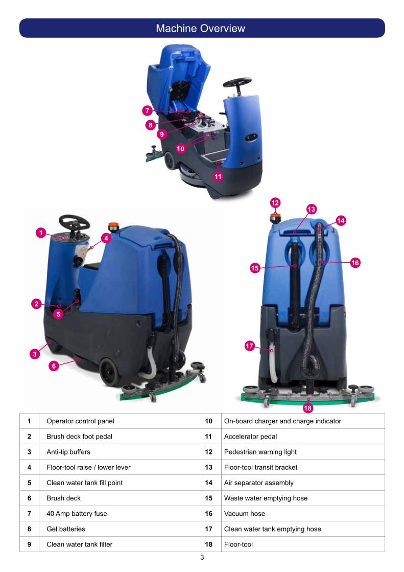
Machine Overview
1 Operator control panel 10 On-board charger and charge indicator
2 Brush deck foot pedal 11 Accelerator pedal
3 Anti-tip buffers 12 Pedestrian warning light
4 Floor-tool raise / lower lever 13 Floor-tool transit bracket
5 Clean water tank fill point 14 Air separator assembly
6 Brush deck 15 Waste water emptying hose
7 40 Amp battery fuse 16 Vacuum hose
8 Gel batteries 17 Clean water tank emptying hose
9 Clean water tank filter 18 Floor-tool
1

4
10
9
8
6543
2
1
1 Water Flow Rate Indicator and Selection Button
2 Brush Engage and Disengage Button
3 Service Indicator
4 Brush Pressure / Load Indicator
5 Run Time Selection Button
6 Battery Charge Level Indicator
7 Off Aisle Vacuum Button
8 On / Off Switch
9 Forward / Reverse Switch
10 LED Status Indicator
11 Maximum Speed Control
12 Horn Button
13 Emergency Stop Button
7
11
12
13
Control Panel Overview

5
Rating Label1 Company Name & Address2 Machine Description3 Power rating4 Voltage Frequency5 Max Gradient6 CE Mark7 Weight (ready to use)8 WEEE Logo9 Ingress Protection Rating
10 Machine yr/wk Serial number10
98
7
6
5
43
2
1 11
No HOT drinks when operating this
machine.
Safety Critical Component:
Charging Leads: Ho5VV-F x 1.0 mm2 x 3 CoreTransaxle 205190Battery Charger (230V) (115V)
About the Machine
WEEE (Waste, Electrical and Electronic Equipment)Scrubber dryer Accessories and packaging should be sorted for environmentally-friendly recycling.Only for EU countries.Do not dispose of scrubber-dryer into household waste.According to the European Directive 2002/96/EC on waste electrical electronic equipment and its incorporation into national law.Scrubber-dryers that are no longer suitable for use must be separated, collected and sent for recovery in an environmentally-friendly manner.
Ear Protection Safety Footwear Head Protection Safety Gloves
Dust/Allergens Protection
Eye Protection Protective Clothing
Hi-Vis Jacket Caution Wet Floor Sign
PPE (Personal protective equipment) that may be required for certain operations.
Note:A risk assessment should be conducted to determine which PPE should be worn.
In the event of a breakdown contact your Numatic dealer or theNumatic Technical help line +44 (0)1460 269268
Caution
12
13
11 Machine Description12 Noise Rating13 Hand Arm Vibration
6
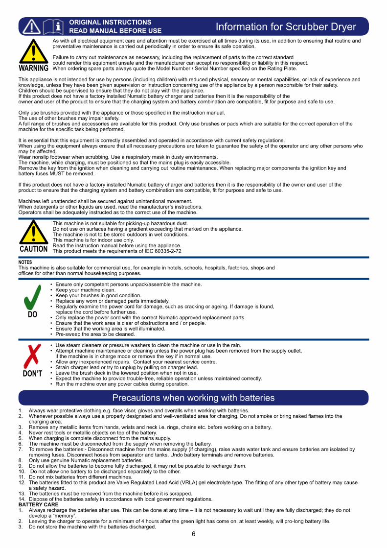
1. Always wear protective clothing e.g. face visor, gloves and overalls when working with batteries.2. Whenever possible always use a properly designated and well-ventilated area for charging. Do not smoke or bring naked flames into the charging area.3. Remove any metallic items from hands, wrists and neck i.e. rings, chains etc. before working on a battery.4. Never rest tools or metallic objects on top of the battery.5. When charging is complete disconnect from the mains supply.6. The machine must be disconnected from the supply when removing the battery. 7. To remove the batteries:- Disconnect machine from the mains supply (if charging), raise waste water tank and ensure batteries are isolated by removing fuses. Disconnect hoses from separator and tanks, Undo battery terminals and remove batteries. 8. Only use genuine Numatic replacement batteries. 9. Do not allow the batteries to become fully discharged, it may not be possible to recharge them. 10. Do not allow one battery to be discharged separately to the other. 11. Do not mix batteries from different machines. 12. The batteries fitted to this product are Valve Regulated Lead Acid (VRLA) gel electrolyte type. The fitting of any other type of battery may cause a safety hazard.13. The batteries must be removed from the machine before it is scrapped.14. Dispose of the batteries safely in accordance with local government regulations.BATTERY CARE1. Always recharge the batteries after use. This can be done at any time – it is not necessary to wait until they are fully discharged; they do not develop a “memory”. 2. Leaving the charger to operate for a minimum of 4 hours after the green light has come on, at least weekly, will pro-long battery life.3. Do not store the machine with the batteries discharged.
Information for Scrubber DryerAs with all electrical equipment care and attention must be exercised at all times during its use, in addition to ensuring that routine and preventative maintenance is carried out periodically in order to ensure its safe operation. Failure to carry out maintenance as necessary, including the replacement of parts to the correct standard could render this equipment unsafe and the manufacturer can accept no responsibility or liability in this respect.When ordering spare parts always quote the Model Number / Serial Number specified on the Rating Plate.
This appliance is not intended for use by persons (including children) with reduced physical, sensory or mental capabilities, or lack of experience and knowledge, unless they have been given supervision or instruction concerning use of the appliance by a person responsible for their safety.Children should be supervised to ensure that they do not play with the appliance. If this product does not have a factory installed Numatic battery charger and batteries then it is the responsibility of the owner and user of the product to ensure that the charging system and battery combination are compatible, fit for purpose and safe to use.
Only use brushes provided with the appliance or those specified in the instruction manual. The use of other brushes may impair safety. A full range of brushes and accessories are available for this product. Only use brushes or pads which are suitable for the correct operation of the machine for the specific task being performed.
It is essential that this equipment is correctly assembled and operated in accordance with current safety regulations.When using the equipment always ensure that all necessary precautions are taken to guarantee the safety of the operator and any other persons who may be affected. Wear nonslip footwear when scrubbing. Use a respiratory mask in dusty environments.The machine, while charging, must be positioned so that the mains plug is easily accessible.Remove the key from the ignition when cleaning and carrying out routine maintenance. When replacing major components the ignition key and battery fuses MUST be removed.
If this product does not have a factory installed Numatic battery charger and batteries then it is the responsibility of the owner and user of the product to ensure that the charging system and battery combination are compatible, fit for purpose and safe to use.
Machines left unattended shall be secured against unintentional movement.When detergents or other liquids are used, read the manufacturer’s instructions.Operators shall be adequately instructed as to the correct use of the machine.
This machine is not suitable for picking-up hazardous dust.Do not use on surfaces having a gradient exceeding that marked on the appliance.The machine is not to be stored outdoors in wet conditions.This machine is for indoor use only.Read the instruction manual before using the appliance.This product meets the requirements of IEC 60335-2-72
NOTESThis machine is also suitable for commercial use, for example in hotels, schools, hospitals, factories, shops and offices for other than normal housekeeping purposes.
• Ensure only competent persons unpack/assemble the machine.• Keep your machine clean.• Keep your brushes in good condition.• Replace any worn or damaged parts immediately.• Regularly examine the power cord for damage, such as cracking or ageing. If damage is found, replace the cord before further use.• Only replace the power cord with the correct Numatic approved replacement parts.• Ensure that the work area is clear of obstructions and / or people.• Ensure that the working area is well illuminated.• Pre-sweep the area to be cleaned.
• Use steam cleaners or pressure washers to clean the machine or use in the rain.• Attempt machine maintenance or cleaning unless the power plug has been removed from the supply outlet, if the machine is in charge mode or remove the key if in normal use.• Allow any inexperienced repairs. Contact your nearest service centre.• Strain charger lead or try to unplug by pulling on charger lead.• Leave the brush deck in the lowered position when not in use. • Expect the machine to provide trouble-free, reliable operation unless maintained correctly.• Run the machine over any power cables during operation.
WARNING
CAUTION
DO
DON’T
ORIGINAL INSTRUCTIONSREAD MANUAL BEFORE USE
Precautions when working with batteries

7
Lift top tank assembly to reveal battery compartment.Always lift between points as illustrated to ensure personal safety (Fig.1).Fit battery fuse into the battery fuse holder as illustrated (Fig.2).Remove transit block from pallet (Fig.3).
Ensure no metal objects come into contact with battery terminals while the batteries are exposed. When inserting the fuse you may notice a spark, this is normal.! !
Insert key into ignition and turn quarter-turn clockwise to the ‘ON’ (1) position, make sure that the forward / reverse switch is set to forward and the speed control is set to low (Fig.4).DO NOT depress accelerator pedal while software initialises.Depress accelerator pedal with right foot and slowly drive machine off of the pallet using the ramp provided (Fig.5).Make sure the ramp is central to the machine and drive off straight.Note: The seat is fitted with a pressure sensor that disables the machine until an operator is seated. When the machine is removed and in a safe position, turn key back to the ‘OFF’ (0) position (Fig.6).
Contents:1 x Operator Manual2 x Battery Charger Lead2 x Keys1 x 40 Amp Fuse (1 x Spare)1 x Maxi Fuse-puller
1
2 3
4 5 6
Quick Set-Up Guide
PLEASE READ BEFORE COMMENCING ANY OPERATIONAFTER THE REMOVAL OF ALL THE PACKAGING, CAREFULLY OPEN AND CHECK THE CONTENTS. !!

8
Lower the floor-tool arm by moving the floor-tool lever to the upper position (See above).Loosen the retaining knobs on the floor-tool and slide onto the holding bracket (Fig.10).Tighten the retaining knobs to finger tight. (Fig.11).Push waste collection pipe onto the floor-tool; ensure a tight fit (Fig.12).
Note: Raise floor-tool again before driving to the cleaning area (See Above).
Always ensure that the machine is switched off before making any adjustments! !
To lower the floor-tool move the floor-tool lever into the upper position (Fig.7/9). To raise the floor-tool move the floor-tool lever into the lower position (Fig.8).
Note: The machine will not operate in reverse with the Floor-tool lowered.
Note: The floor-tool lever guide is designed to be reversible and replaceable.
The floor-tool design incorporates a safety knock-off feature.
Allowing it to safely disengage from its mounting should it become caught on an obstruction during forward movement (Fig.13).
Make sure you do not over tighten the retaining knobs to ensure correct operation.
7 98
10 11 12 13
Machine Set-Up
Raise / Lower the Floor-tool
Fitting the Floor-tool
Break-away Floor-tool
9
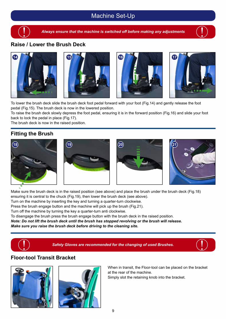
To lower the brush deck slide the brush deck foot pedal forward with your foot (Fig.14) and gently release the foot pedal (Fig.15). The brush deck is now in the lowered position.To raise the brush deck slowly depress the foot pedal, ensuring it is in the forward position (Fig.16) and slide your foot back to lock the pedal in place (Fig.17). The brush deck is now in the raised position.
Make sure the brush deck is in the raised position (see above) and place the brush under the brush deck (Fig.18) ensuring it is central to the chuck (Fig.19), then lower the brush deck (see above).Turn on the machine by inserting the key and turning a quarter-turn clockwise.Press the brush engage button and the machine will pick up the brush (Fig.21).Turn off the machine by turning the key a quarter-turn anti clockwise.To disengage the brush press the brush engage button with the brush deck in the raised position.Note: Do not lift the brush deck until the brush has stopped revolving or the brush will release.Make sure you raise the brush deck before driving to the cleaning site.
Safety Gloves are recommended for the changing of used Brushes.! !
Always ensure that the machine is switched off before making any adjustments! !
When in transit, the Floor-tool can be placed on the bracket at the rear of the machine. Simply slot the retaining knob into the bracket.
14 15 16 17
18 19 20 21
Machine Set-Up
Raise / Lower the Brush Deck
Fitting the Brush
Floor-tool Transit Bracket

10
Always ensure that the machine is switched off before making any adjustments! !The CRO 8055 is equipped with a large capacity 80 litre clean water tank, allowing for large areas to be covered in a single fill.
To fill the clean water tank extend the Flexifill hose, remove the rubber seal and fill from a suitable water outlet (Fig.22). Replace seal and hose to original position when finished.Alternatively unscrew the filler cap completely (Fig.23) and fill the tank using a hose or preferred method (Fig.24).
Note: Great care must be taken to ensure that contaminants (leaves, hair, dirt, etc.) are not allowed to enterthe clean-water tank during the filling process. If using a bucket or similar, ensure it is always clean and freefrom debris.
When filling the clean water tank, do not fill above the clean water tank emptying hose retaining clip (Fig.25). This can be found at the rear of the machine.
22 23 24
25
If you need to access the batteries, make sure that thewaste-water tank is empty before lifting.! !
Machine Set-Up
Filling the Clean-water Tank
Fill Level Indicator

11
= No Flow = 0.5 L/min = 1.0 L/min = 1.5 L/min = 2.0 L/min = 3.0 L/min
IMPORTANTDo not operate machine unless the operator manual has been read and fully understood.! !
The machine is now ready to be driven to the cleaning site (see the quick set-up guide if necessary).Before performing the cleaning operation, place out appropriate warning signs and sweep or dust-mop the floor.
When you have arrived at the cleaning site, lower the Floor-tool (see page 8) and the brush deck (see page 9).
Insert the key into the on / off switch and quarter-turn it clockwise to the ‘ON’ (1) position (Fig.26).
The battery charge-level indicator will illuminate (Fig.27).
Set the water flow rate as required, depending on floor type and level of soiling.
The vac shut off system fitted to your machine stops the airflow when the top tank is full!
It does not shut the power off to the vac motor, the vac motor will continue to run, but there is an audible difference in the sound when the shut off system operates.
See Page 16 for more details on checking and cleaning the shut off system.
Always ensure that the floor is pre-swept andrelevant safety signs are displayed.! !
26 27
Machine Operation
Setting the Cleaning Controls
Waste-water Tank Full
12
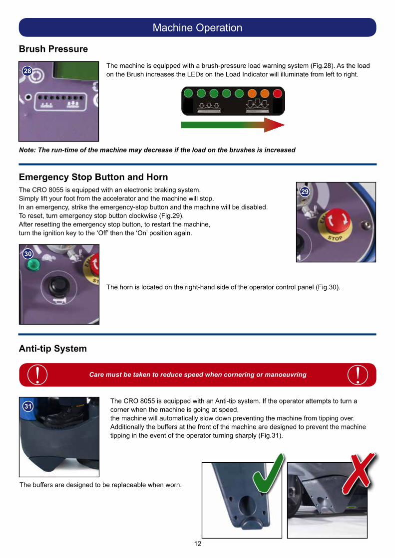
The machine is equipped with a brush-pressure load warning system (Fig.28). As the load on the Brush increases the LEDs on the Load Indicator will illuminate from left to right.
Note: The run-time of the machine may decrease if the load on the brushes is increased
The CRO 8055 is equipped with an electronic braking system.Simply lift your foot from the accelerator and the machine will stop.In an emergency, strike the emergency-stop button and the machine will be disabled.To reset, turn emergency stop button clockwise (Fig.29).After resetting the emergency stop button, to restart the machine,turn the ignition key to the ‘Off’ then the ‘On’ position again.
The horn is located on the right-hand side of the operator control panel (Fig.30).
The CRO 8055 is equipped with an Anti-tip system. If the operator attempts to turn a corner when the machine is going at speed,the machine will automatically slow down preventing the machine from tipping over. Additionally the buffers at the front of the machine are designed to prevent the machine tipping in the event of the operator turning sharply (Fig.31).
Care must be taken to reduce speed when cornering or manoeuvring ! !
28
29
30
31
The buffers are designed to be replaceable when worn.
Machine Operation
Brush Pressure
Emergency Stop Button and Horn
Anti-tip System

13
To operate, select forward, press the accelerator pedal.
Vacuum pick-up and water-flow will turn on if selected and the brush and floor tool are in the lowered position, the machine will move forward.
Clean water is dispersed evenly via ‘THRU- FEED’ scrubbing brushes.
The waste water is then retrieved by the suction floor-tool (Fig.32).Overlap each scrubbing path by 10cm to ensure an even clean.
After stopping the Vac motor will run for a further 10 seconds to collect any water left in the vacuum hose.
Do not operate the machine on inclines that exceed 11%.! !If streaking occurs wipe floor-tool blades clean (Fig.33).On heavily soiled floors use a ‘double scrub’ technique.First pre-scrub the floor with thefloor-tool in the raised position, allow the chemicals time to work then scrub the area a second time with the floor-tool lowered (Fig.34).
Use the maximum speed control knob and set desired traction speed as required, depending on floor type and level of soiling (Fig.35).
Keep speed setting within the white gradient on the dial for optimum floor cleaning. The grey gradient on the dial is for setting the transit speed.
32
3433
35
Cleaning Transit
Once the Max speed has been set using the control knob on the control panel, fine adjustments can be made using the variable control speed pedal located on the right side of the footplate.
Machine Operation
Machine in Use
Maximum Speed Control

14
Off-Aisle Cleaning Kit (Optional Extra Accessory ) 606182
The vacuum hose has a U-bend clip which creates a U-bend in the hose preventing water spillage when the vacuum is switched off. If you need to remove the U-bend clip for any reason always ensure it is refitted correctly before you resume operation (Fig 36-39).
37
38 39
40
41
The optional off-aisle cleaning kit gives added flexibility to the operator.The kit can be used to clean hard to reach / inaccessible areas (Fig 40).
Remove the Vacuum hose from the Floor-tool and attach to the Off-aisle kit.
To operate the vacuum, press the Off-aisle vacuum button on thecontrol panel.
Pressing the Off-aisle Button again will switch the vacuum off (Fig 41).
Note: DO NOT push the vacuum hose onto the Floor-tool with the Floor-tool in the raised position.
Machine Operation
Hose U-bend Clip
Note: Return the hose to the floor-tool once finished using the off-aisle facility.
Refit vacuum hose to the Floor-tool when finished.
36

15
Always ensure that the machine is switched off prior to any maintenance.! !After use, empty waste-water tank using emptying hose and flush-out with clean water.
Next remove floor-tool vacuum hose ensuring you remove the U-bend clip and flush out with clean water.
Next empty clean water tank, using emptying hose and again flush out with clean water.
Before removing the separator, first pull off the connected hose (Fig.42).Remove the separator and rinse using clean water (Fig.43).The separator also has a sealing-rubber which should be examined at everyclean-down (Fig.44).
Note: The separator can be hung from either side of the top tank while you maintain the machine using the clip on the front of the lid. (Fig.45).
A
B
C
A
B
C
42 43 44
45
When refitting the separator make sure you engage the tab (A) at the front of the separator BEFORE pushing the separator down.
Refit the vacuum hose.
A
Machine Cleaning
16
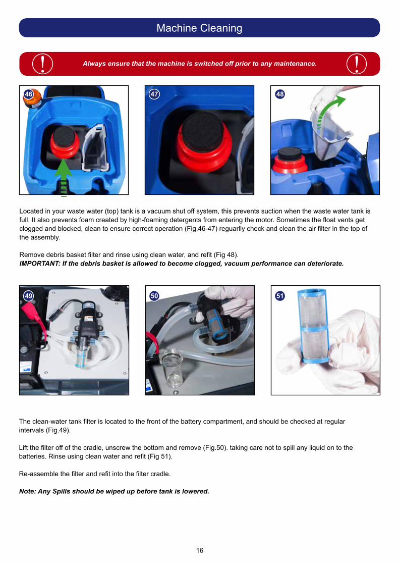
Located in your waste water (top) tank is a vacuum shut off system, this prevents suction when the waste water tank is full. It also prevents foam created by high-foaming detergents from entering the motor. Sometimes the float vents get clogged and blocked, clean to ensure correct operation (Fig.46-47) reguarlly check and clean the air filter in the top of the assembly.
Remove debris basket filter and rinse using clean water, and refit (Fig 48).IMPORTANT: If the debris basket is allowed to become clogged, vacuum performance can deteriorate.
The clean-water tank filter is located to the front of the battery compartment, and should be checked at regular intervals (Fig.49).
Lift the filter off of the cradle, unscrew the bottom and remove (Fig.50). taking care not to spill any liquid on to the batteries. Rinse using clean water and refit (Fig 51). Re-assemble the filter and refit into the filter cradle.
Note: Any Spills should be wiped up before tank is lowered.
Always ensure that the machine is switched off prior to any maintenance.! !46 47 48
49 50 51
Machine Cleaning
17
Always ensure that the machine is switched off prior to any maintenance.! !
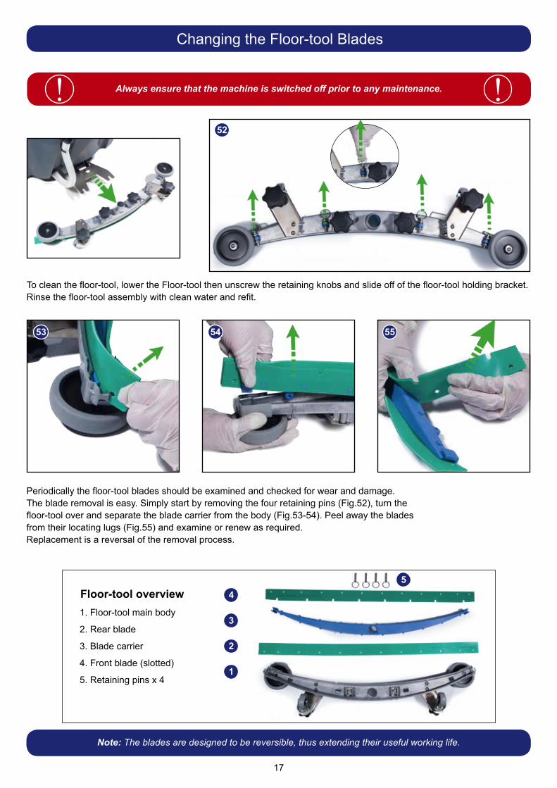
To clean the floor-tool, lower the Floor-tool then unscrew the retaining knobs and slide off of the floor-tool holding bracket.Rinse the floor-tool assembly with clean water and refit.
Periodically the floor-tool blades should be examined and checked for wear and damage.The blade removal is easy. Simply start by removing the four retaining pins (Fig.52), turn thefloor-tool over and separate the blade carrier from the body (Fig.53-54). Peel away the bladesfrom their locating lugs (Fig.55) and examine or renew as required.Replacement is a reversal of the removal process.
53 54 55
52
4
2
3
1
5
Note: The blades are designed to be reversible, thus extending their useful working life.
Changing the Floor-tool Blades
Floor-tool overview1. Floor-tool main body
2. Rear blade
3. Blade carrier
4. Front blade (slotted)
5. Retaining pins x 4

18
If your machine leaves streaks on the cleaned floor, either clean the floor-tool blade (See page 13)
oradjust blade pressure for optimum performance.
Floor-tool Height Adjustment

19
Always ensure that the machine is switched off prior to charging.! !
As the machine is used and the batteries are discharged, the meter lights will go out from right to left.
The large capacity gel batteries are sealed for life and are totally maintenance free. The on-board charger automatically monitors the charging process and will switch off when the batteries are fully charged.The machine charging point is located above the foot plate (See page 3 : Item 10).Insert the charging lead (Fig.56) required for your country into the charging point and connect to a suitable power supply (Fig.57).
Note: The Charging Lead supplied with your machine may differ than the lead shown.Once the charging lead has been connected the red charging indicator will illuminate and the display panel will show ‘INHIBITED’.The battery charge indicator display lights will flash in unison.The machine will not operate.To ensure a full charge, the machine should be left until the charging indicator shows green.Once fully charged, disconnect the charging lead from both the power supply and the machine.
If the battery-charge level is allowed to discharge to the point that only three red lights remain illuminated (and begin to flash), all cleaning functions will automatically be disabled and the operator should drive the machine straight to a suitable charge point.
56 57
See page 21
*NoteCharger viewing panel only available on certain models.
Machine Charging
The battery charge indicator displays the charge level of the batteries;when fully charged, all meter lights are illuminated.
If the battery-charge level is allowed to discharge to the point that only three red lights are illuminated, the operator must consider charging the machine.
50-100% 20-50% 0-20%

20
ALWAYS ENSURE THAT THE MACHINE IS ON LEVEL GROUNDBEFORE DISENGAGING BRAKE ARM.
NEVER DISENGAGE THE BRAKE WHEN THE MACHINE IS ON A SLOPE / GRADIENT.! !The CRO 8055 is equipped with a free-wheel function that will enable the operator to move the machine.
When the brake is disengaged the machine is in Free-wheel mode and has no braking facility. Care must be taken when moving the machine in Free-wheel mode.! !
The Free-wheel lever can be found on the right hand side of the rear axle (Fig.58).To disengage the brake, pull the lever into the down position (Fig.59).Re-engage the brake by moving the lever into the up position.
To ensure your machine remains at its maximum efficiency and prolong your battery life, please follow the simple steps below:
Under normal daily usage:Recharge batteries after each use regardless of machine operation time.
Recharge the machine fully after its last use.Do not leave the machine in a discharged state.
58 59
Free-wheel Function
Battery Care

21
Signal (LED) Meaning
Red LED on First Phase (constant current Mode)
Orange LED on Second Phase (Constant Voltage Mode)
Green LED on Third Phase (Constant Voltage Mode) Charge Complete
Red LED flashingfollowed by Pause
Cooling Fan Locked > 1 flash between pause
Over Voltage Protection / Output Short Circuit / Battery Reverse Polarity > 2 flashes between pause
Over Temperature Protection > 3 flashes between pause
Charge Time has exceeded 10 hrs during phase 1 or 2 > 4 flashes between pause
Under abnormal use; i.e. leaving the machine without charging for a period of time,we advise that you follow these steps:
If the machine will be standing unused for a period of 30 days or more, then batteries must be fully charged and battery fuses removed using the Maxi fuse-puller provided, prior to this period.
Batteries should be recharged every three months. Charge fully the day before you start using the machine again.
*NoteOnly available on certain models.
Battery Care
Viewing Panel Charging Light Sequence

22
Gre
en S
tatu
s In
dica
tor
Faul
tPo
ssib
le C
ause
Effe
ct o
n Pr
oduc
tIn
vest
igat
e th
e Fo
llow
ing
Act
ion
Req
uire
dIf
Faul
t Per
sist
s
1 F
lash
with
pau
seB
atte
ries
volta
ge lo
wB
atte
ries
not b
een
char
ged
Ope
ratin
g tim
e se
vere
ly re
duce
d or
mac
hine
will
not
op
erat
e
Che
ck w
hen
mac
hine
last
cha
rged
Cha
rge
batte
ries
imm
edia
tely
Pos
sibl
e ba
d co
nnec
tion
betw
een
batte
ries,
co
ntro
ller,
char
ger o
r fu
ses
caus
ed b
y lo
ose
conn
ectio
ns, d
amag
ed
wiri
ng, w
ater
ingr
ess
Sw
itch
OFF
the
mac
hine
: R
emov
e Fu
ses
Che
ck c
onne
ctio
ns to
bat
terie
s, c
harg
er a
nd fu
ses
for l
oose
wire
s or
scr
ews
Tigh
ten
loos
e co
nnec
tions
an
d re
plac
e da
mag
ed
com
pone
nts
Not
acc
eptin
g ch
arge
due
to
faul
ty b
atte
ry /
cell
Che
ck e
ach
batte
ry V
olta
ge in
divi
dual
ly to
det
ect
defe
ct u
nit 1
0.5V
min
Rep
lace
bat
terie
s as
re
quire
d
Cha
rger
not
func
tioni
ngC
heck
bat
tery
vol
tage
and
cha
rge
curr
ent e
nsur
ing
char
ger r
ed fa
ult l
ight
is e
xtin
guis
hed.
Rep
lace
cha
rger
2 Fl
ashe
s w
ith p
ause
Trac
tion
mot
or
disc
onne
cted
The
mot
or h
as a
bad
co
nnec
tion
The
mot
or w
ill n
ot
oper
ate
Che
ck a
ll co
nnec
tions
and
lead
s be
twee
n m
otor
an
d co
ntro
ller
Tigh
ten
loos
e co
nnec
tions
an
d re
plac
e da
mag
ed
com
pone
nts.
Mot
or d
isco
nnec
ted
TCO
act
ivat
ed
(The
rmal
Cut
Out
)
Mot
or fa
iled
to o
pen
circ
uit
3 Fl
ashe
s w
ith p
ause
Trac
tion
mot
or w
iring
tri
pTh
e m
otor
has
a s
hort
circ
uit
to a
bat
tery
Mot
or w
ill n
ot o
pera
teC
heck
all
conn
ectio
ns a
nd le
ads
betw
een
the
mot
or a
nd c
ontro
ller
4 Fl
ashe
s w
ith p
ause
Bat
tery
Loc
kout
The
batte
ry c
harg
e le
vel
has
falle
n be
low
the
batte
ry lo
ckou
t lev
el a
nd
the
cont
rolle
r is
inhi
bitin
g m
achi
ne fu
nctio
ns
Mac
hine
func
tions
no
t wor
king
Che
ck b
atte
ry v
olta
ge a
nd c
harg
e cu
rren
t ens
urin
g ch
arge
r red
faul
t lig
ht is
ext
ingu
ishe
dC
harg
e ba
tterie
s im
med
iate
ly
Che
ck e
ach
batte
ry v
olta
ge in
divi
dual
ly to
det
ect
defe
ct u
nit 1
0.5V
min
6 Fl
ashe
s w
ith p
ause
Cha
rger
con
nect
edTh
e co
ntro
ller i
s be
ing
inhi
bite
d fro
m d
rivin
g, th
is
may
be
beca
use
the
batte
ry
char
ger i
s co
nnec
ted
Mac
hine
func
tions
no
t wor
king
Rem
ove
char
ger t
o op
erat
e m
achi
ne
8 Fl
ashe
s w
ith p
ause
Con
trolle
r trip
A co
ntro
ller t
rip is
indi
cate
dM
achi
ne fu
nctio
ns
not w
orki
ngC
heck
all
conn
ectio
ns a
nd le
ads
Tigh
ten
loos
e co
nnec
tions
an
d re
plac
e da
mag
ed
com
pone
nts
9 Fl
ashe
s w
ith p
ause
Bra
ke d
eact
ivat
ed o
r fa
iled
Poo
r bra
ke c
onne
ctio
ns.
Bra
ke fa
ilure
or d
eact
ivat
ion
Trac
tion
driv
e di
sabl
edC
heck
bra
ke w
iring
and
bra
ke le
ver
Rep
lace
bra
ke o
r wiri
ng
as n
eces
sary
. Rea
ctiv
ate
brak
e by
eng
agin
g br
ake
leve
r
10 F
lash
es w
ith p
ause
Hig
h ba
ttery
vol
tage
Poo
r con
nect
ions
bet
wee
n ba
ttery
con
trolle
r and
tra
ctio
n m
otor
Mac
hine
func
tions
no
t wor
king
Che
ck e
ach
batte
ry V
olta
ge in
divi
dual
ly to
ens
ure
volta
ge <
14
volts
Che
ck c
onne
ctio
ns o
n co
ntro
ller b
atte
ries
and
tract
ion
mot
or
Che
ck c
ombi
ned
batte
ry p
ack
volta
ge is
< 2
8 vo
lts
Contact Service Agent.

23
LCD
Dis
play
Faul
tPo
ssib
le C
ause
Effe
ct o
n Pr
oduc
tIn
vest
igat
e th
e Fo
llow
ing
Act
ion
Req
uire
dIf
Faul
t Pe
rsis
tsB
lank
* N
o po
wer
* K
ey s
witc
hed
off
* E
mer
genc
y st
op p
ress
ed*
Mac
hine
will
not
ope
rate
* K
ey s
witc
hed
off
* E
mer
genc
y st
op p
ress
ed*
Sw
itch
key
on*
Rel
ease
em
erge
ncy
stop
‘OV
ER
CU
RR
EN
T’*
Bru
sh o
ver c
urre
nt*
Bru
sh p
ress
ure
too
grea
t*
Bru
sh c
urre
nt e
xcee
ds 3
2A*
Wro
ng ty
pe o
f bru
sh fo
r sur
face
* Va
c. b
rush
, wat
er &
D
eter
gent
mot
ors
/ pum
p w
ill n
ot o
pera
te
* B
rush
LE
D’s
all
flash
in
unis
on u
ntil
the
Ped
al is
re
leas
ed
* R
elea
se b
rush
pre
ssur
e*
Cha
nge
type
of b
rush
* R
esta
rt m
achi
ne
‘UN
DE
R V
OLT
S’
* B
atte
ry v
olta
ge d
ropp
ed
bel
ow 2
1 Vo
lts*
Left
mos
t bat
tery
LE
D fl
ashe
s*
Bat
terie
s re
quire
rech
argi
ng*
Faul
ty c
ell o
n ba
ttery
* M
achi
ne w
ill n
ot o
pera
te*
Bat
tery
lead
s an
d co
nnec
tions
* C
harg
e ba
tterie
s*
Rep
lace
bat
tery
(if
cel
l dam
aged
)
‘VA
C O
VE
R C
UR
RE
NT’
* Va
cuum
mot
or fa
ult
* D
ebris
ent
erin
g va
cuum
mot
or*
Wat
er in
gres
s*
Mac
hine
dis
able
d*
Res
tart
mac
hine
* R
epla
ce v
acuu
m m
otor
‘INH
IBIT
ED
’
MA
CH
INE
INH
IBIT
ED
- N
O O
PE
RAT
ION
Contact Service Agent
To v
iew
CR
O 8
055
run
time
info
rmat
ion
turn
the
key
to th
e ‘O
N’ p
ositi
on.
Pre
ss th
e ru
n-tim
e in
form
atio
n bu
tton
to c
ycle
bet
wee
n th
e di
ffere
nt m
odes
.
T =
Tr
actio
n ru
n-tim
e V
=
Vacu
um to
tal r
un-ti
me
B =
B
rush
tota
l run
-tim
e
W =
W
ater
Pum
p to
tal r
un-ti
me
Trou
ble
Sho
otin
g

24
PROBLEM CAUSE SOLUTIONMachine will not operate Missing or blown fuses
Key in the ‘OFF’ positionLow battery chargeMachine stop button in ‘OFF’ modeMachine is connected and charging
Fit or replace fuse (page 7)Turn key to ‘ON’ position (page 7)Charge batteries (page 19)Reset stop button (page 12)Take off charge (page 19)
Vacuum will not operate Floor tool in raised position Waste water tank full
Lower floor-tool (page 8)Empty waste water tank (page 15)
Poor water pick-up Waste-water tank fullClogged / blocked vacuum hoseLoose hose connections Debris basket filter clogged / blockedSeparator air filter clogged / blockedPoor separator sealDamaged separator sealDamaged / split vacuum hoseDamaged floor-tool bladesLow battery charge
Empty waste-water tank (page 15)Remove and clean (page 15)Push tight connections (page 14)Remove and clean (page 16)Remove and clean (Page 15)Clean and refit (page 15)Renew (contact service dept)Renew (contact service dept) Renew (contact service dept)Recharge batteries (page 19)
No brush / scrub function No brushes fittedBrush deck raised
Check and fit (page 9)Lower brush deck (page 9)
Little or no water flow Clean-water tank emptyClean-water tank filter blocked/ cloggedIncorrect water flow settingBrush deck raised
Fill clean-water tank (page 10)Remove and clean (16)Adjust as desired (Page 11)Lower brush deck (page 9)
Machine just ‘stops’ while operating
Too much load on the brush system Reset the machine using the key and decrease the brush load to best suit the floor type (page 12)
Trouble Shooting
Model - CRO 8055(Empty) Net Weight
120 A/HrBrush Weight
Brush Width
BrushPressure
Pad Width
Pad Pressure Brush Motor Vac
motor
200 kg 23 kg 550 mm 11.4 G/cm2 508 mm 9.3 G/cm2 24V600 W
24 V 400 W
Transaxle Run Time2 x 120 A/Hr
Run Time2 x 100 A/Hr
Total Battery Weight
120 A/Hrs
Total BatteryWeight
100 A/Hrs
Charge Times2 x 120 A/Hrs
Charge Times2 x 100 A/Hrs
24 V 400 W 3 hrs 2 hrs 74 kg
(163 lbs)62 kg
(136 lbs)
10A = 12 hrs20A = 7 hrs
35A = 4.5 hrs
10A = 8 hrs20A = 5-6 hrs35A = 3-4 hrs
Brush Speed AirFlow Transit
Speed Capacity Water Flow Rates
Cleaning Area Sound Pressure Hand Arm
Vibration
150 rpm 24.2 L/sec 0-6 km/hr 80 L / 80 L
0.5 / 1.0 / 1.5 2.0 / 3.0L/min
1700 m2
@ 3.5 K/Hr ≤ 70dB (A)
Travelling (Quarry Tiles)1.84 m/s2
(Uncertainty 0.92 m/s2)ISO 5439-1
Whole Body Vibration Height Length WidthTravelling (Quarry Tiles)
1.11 m/s2
(Uncertainty 0.56 m/s2)ISO 2431-1
1160 mm 1460 mm 805 mm
Specifications

25
Spare Parts
BRUSHES: TOP TANK:
606028 550 mm Polyscrub Brush 207000 Grit Filter Basket
606550 550 mm Nyloscrub Brush 208861 Air-Filter
900526 500 mm Nuloc2 Drive Board 208980 Cro Foam Pad
SQUEEGEE: 304503 Separator Seal Strip 1045 mm Long
599469 Complete 650 mm Squeegee Assembly 208862 Seat Pad
900518 Squeegee Blade Set - Serilor PU Green FR & RR 208864 Back Pad
208497 Squeegee Castor 208867 Beacon Light
206953 Detent Pin 208907 Gas Strut (100Nm)
208796 Squeegee Buffer Wheel 220386 Charging Lead V17 - UK
604013 Squeegee Lift Inner Cable Kit 221079 Chargling Lead V34 - EURO
208156 M6 Pinch Bolt BOTTOM TANK & STEERING COLUMN:
FILTERS: 237685 Bottom Tank Scuff Moulding Left Hand
230278 Water Pump 237684 Bottom Tank Scuff Moulding Right Hand
208888 Extended Filter Complete Assembly 303942 Deck Buffer Wheel
208827 Strainer Black Top 208985 Lift Handle Nylon Guider
208889 Extended Strainer 50 Mesh Screen 392438 Bottle Plate
208830 Strainer Gasket 208897 Steering Drive Belt
208890 68 mm Extended Strainer Clear Bowl 204120 Front Wheel
HOSES: 901209 Rear Wheels
280017 Squeegee Suction Hose 237609 Splash Skirt
237718 3 Ring Hose Guide
208938 Bottom Tank Dump Hose
213061 Top Tank Dump Hose
206842 Filler Stretch Hose

26
EU DECLARATION OF
CONFORMITYWe hereby declare under our sole responsibility that the following equipment fulfils all the relevant provisions of the following EU Directives:
Machine Description: Scrubber Dryer Type: TTV, TRO, CRO series
Relevant standards upon which conformity is declared include:
IEC 60335-1 2001 + A1 2004 + A2 2006 + National DeviationsIEC 60335-2.72 Ed 2.0
EN 55014-1:2006EN55014-2:1997+A1EN61000-3-2:2006EN61000-3-3:1995+A1+A2BS EN 62233:2008
A technical construction file for this equipment is retained at the manufacturer’s address under the authorisation of the following signatory:
Signed: Date: 20/04/2016Numatic International Limited, Chard , Somerset. TA20 2GB www.numatic.co.uk GB
16
Position: Technical ManagerName:Allyn Boyes
Manufactured by: Numatic International Limited
Machinery Directive 2006/42/ECEMC Directive 2014/30/EURoHS Directive 2011/65/EU
Schematic Diagram
In the event of a breakdown contact your Numatic dealer or theNumatic Technical help line +44 (0)1460 269268
EU Declaration of Conformity

27

28244488 04/16 (A06)
CRO 8055/100TCRO 8055/120T
Numatic International LimitedChard, Somerset
TA20 2GB ENGLAND.Telephone 01460 68600 Fax: 01460 68458
www.numatic.co.uk
Specification subject to change without prior noticewww.numatic.co.uk © Numatic International Limited
This machine has been packed with the following:
Charging Lead
Fuses
Keys
Signed
Distributed by
This Product has been comprehensively inspected and checked during every stage of its manufacture.including an in-depth electrical safety and functionality test.