Embed Size (px)
Citation preview
‘The research leading to these results was derived from the
European Community’s Seventh Framework Programme (FP7) under
Grant Agreement number 248454 (QoSMOS)’.
Quality Of Service and MObility driven cognitive radio Systems
Overview of the EU-project QoSMOS PMSE Workshop, DLR, Berlin
Michael Fitch
7th December 2011

Two trends are occurring:
1. Cells are becoming smaller...
2
Higher data
rates and
more users
Large signal
strength
Large
spectrum use
Smaller cells
(including self
-install)
Approx linear relationship
Need to re-use
spectrum over
shorter distances
Self-organising
networks
Planning is infeasible
Non-linear relationship
Impossible transmit
powers over long distances

Licensed
Unlicensed EG WiFi
Bluetooth
EG GSM, 3G
Shared EG TV White
Space
Flexible radios
Intelligent use
of spectrum
resources
Low power
Unplanned
Interference
High Power
Radio Planning
Spectrum shortage
Medium Power
Dynamic planning
My 5 year vision is
very flexible and
reconfigurable
user terminals.
And managed use
of spectrum.
2. Regulation is changing to allow spectrum sharing
- to enable more efficient use of the spectrum

Response to these trends….
• Spectrum sharing using Cognitive Radio
as the enabling technology
– Collaborative projects, such as QoSMOS and
Cambridge TVWS group,
– BT In-house trials and use-case assessment
– QoSMOS to provide technology and business
models
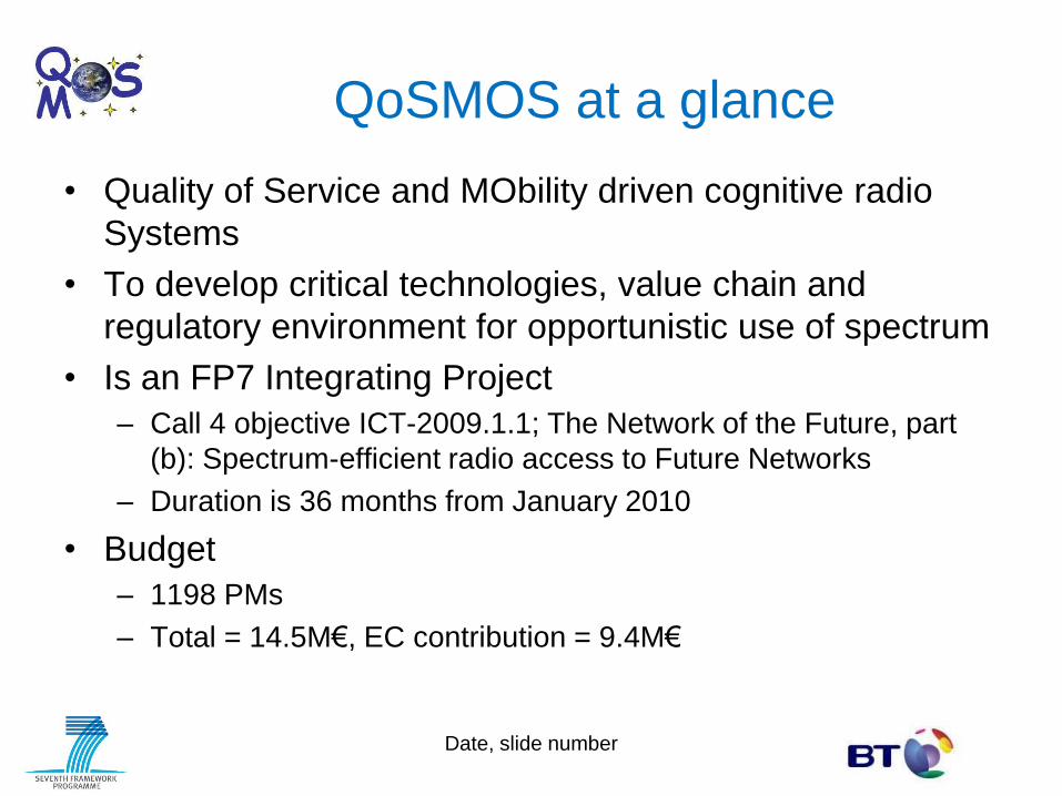
QoSMOS at a glance
• Quality of Service and MObility driven cognitive radio
Systems
• To develop critical technologies, value chain and
regulatory environment for opportunistic use of spectrum
• Is an FP7 Integrating Project
– Call 4 objective ICT-2009.1.1; The Network of the Future, part
(b): Spectrum-efficient radio access to Future Networks
– Duration is 36 months from January 2010
• Budget
– 1198 PMs
– Total = 14.5M€, EC contribution = 9.4M€
Date, slide number

Partners
7 December 2011, 6
Participant no. Participant organisation name Part. short
name
Country
1 (Coordinator) British Telecommunications PLC BT United Kingdom
2 Telenor ASA TEL Norway
3 Commissariat à l’Energie Atomique CEA France
4 Oulun Yliopisto UOULU Finland
5 Technische Universität Dresden TUD Germany
6 Instituto de Telecomunicões IT Portugal
7 NEC Technologies (UK) Ltd NTUK United Kingdom
8 Agilent Technologies Belgium NV AGILENT Belgium
9 Thales Communications SA TCF France
10 University of Surrey UNIS United Kingdom
11 NEC Corporation NEC Japan
12 Fraunhofer-Gesellschaft zur Förderung
der angewandten Forschung e.V.
Fraunhofer Germany
13 TST Sistemas SA TST Spain
14 Alcatel-Lucent Deutschland AG ALD Germany
15 Budapesti Műszaki és
Gazdaságtudományi Egyetem
BME Hungary
Objectives
• The main objective is to provide a platform for efficient
radio access to future networks
• Under this are two S & T objectives
– Cognitive Wireless Access Provision [measurable criteria]
• Platform aspects
• Intelligence aspects
– Network Support Provision [measurable criteria]
• And two non-S & T objectives
– Use-case development [guidelines on marketing]
– Preparation of regulatory policies [response of regulators]
7 December 2011, 7
7 December 2011, 8
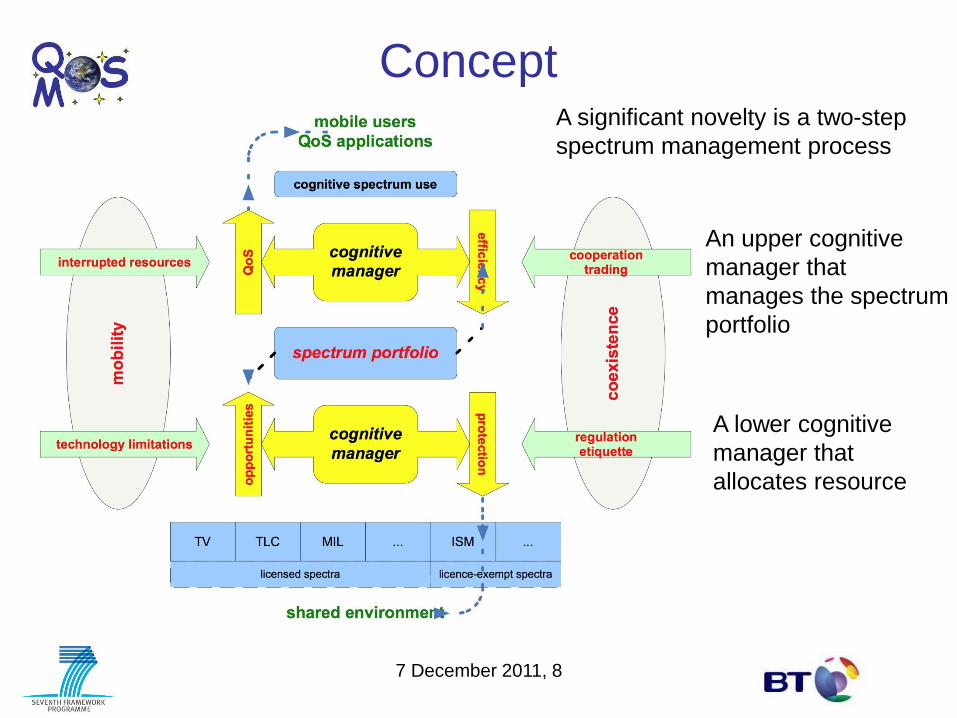
Concept
An upper cognitive
manager that
manages the spectrum
portfolio
A lower cognitive
manager that
allocates resource
A significant novelty is a two-step
spectrum management process

Wanted outcomes
• to develop the critical technologies to allow spectrum sharing
• to establish confidence of regulators, primary and other secondary users that spectrum sharing can be achieved without causing harmful interference
• to provide a forum that encourages framework alignment
across Europe so that the market is big enough for
equipment that give a high user satisfaction at the right
price
• to give terminal deployment guidelines – antenna
spacing etc
• to give network deployment guidelines – database
integration etc

Role of the QoSMOS advisory
board Advisory board:
ANFR
BNetzA
RA-NL
AT4wireless
WinnF
BBC
Microsoft
NXP
Ofcom UK
Ofcom Swiss
SWR
ETSI RRS
Bosch
Steering and
deliverable reviews QoSMOS
Five meetings
aligned with project
milestones
Dissemination route
The advisory group remains open to other organisations

QoSMOS rationalised scenarios Scenario Range LoS Datarate Mobile Suitable
Frequency Dynamic backhaul 10 km Maybe High
(10–
50Mbit/s)
No >2GHz if LoS,
<1GHz if non-
Los
Cellular extension in White
Space
0.1 – 10 km No Med (2 –
10Mbit/s)
Yes >1GHz if <1km
Rural Broadband 1 – 10 km Maybe Med No >2GHz if LoS,
<1GHz if non-
Los
Cognitive ad hoc Network 1 – 1000 m No Med Yes >2GHz if
<50m
Direct Terminal-to-Terminal in
Cellular
10 – 1000 m No Low
(<2Mbit/s)
No >2GHz if
<50m
Cognitive femtocell 1 – 100 m No Med Maybe >2GHz if
<50m
Rationalisation was carried out through questionnaires to Stakeholders
in the value chain and includes technical and Commercial feasibility.
The final column on the right is my addition

Terminal for sub-system1
RAN of sub-system1
Spectrum Management
(WP6)
Sensing
WP3 Transceiver
WP4
BTS#1
User Plane
Protocol
Stack
(L1-L5)
Cognitive manager
(WP5)
Spectrum
Mngt Sensing Transceiver
WP6 WP
3
WP4
BTS#2 BTS#2
User Plane
Protocol
Stack
Cognitive manager
(WP5)
Spectrum
Mngt Sensing Transceiver
WP6 WP
3
WP4
User Plane
Protocol Stack
L1-L2
Country-wide regulation constraints database
User Plane
Protocol Stack L3
Spectrum Management
(WP6)
To other
Spectrum
Manager(s)
Core Network
of QoSMOS system
To other
terminals To other
terminals
RAN of sub-system2
Terminal for sub-system2
Cognitive control flow
(logical I/F)
Enablers
Cog. Mng
WP5
Internal I/F
Spectrum Management
(WP6)
Sensing
WP3 Transceiver
WP4
User Plane
Protocol Stack
L1-L2
Cog. Mng
WP5
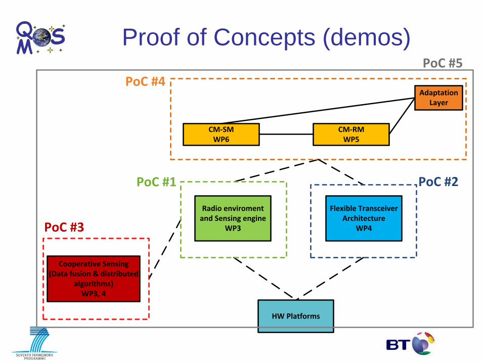
Proof of Concepts (demos)
Radio enviroment and Sensing engine
WP3
Cooperative Sensing(Data fusion & distributed
algorithms)WP3, 4
Flexible Transceiver Architecture
WP4
CM-SMWP6
CM-RMWP5
PoC #5
PoC #4
PoC #1 PoC #2
PoC #3
Adaptation Layer
HW Platforms
Three examples of QoSMOS
outcomes
• Wireless microphone detection
• Filter block modulation modelling
– Prototype being built for demo in December in
March 2012
• TVWS availability database
7 December 2011, 14

Wireless microphone detection Spectrum generated by Matlab model to EN 300 422

• Teager Kaiser detector – Use the knowledge and the characteristics of FM modulation
Teager-Kaiser energy detector [Crowncom2010]
Y[s(k)]=[s(k)]2-s(k+1)s(k-1)
• Frequency domain detection – Narrowband condition:
Detection in the frequency domain
Efficient implementation based on FFT for the energy
detection
Wireless microphone detection

Filter bank transceiver
Subchannel frequency responses
= Frequency-shifted versions of a prototype

FBMC transceiver
Due to the overlapping of neighbouring sub-channels, orthogonality is needed.
Use of Offset-QAM model:
- Each QAM symbol is mapped to two consecutive subcarrier samples.
- Subcarrier sample sequences are oversampled by a factor of 2.

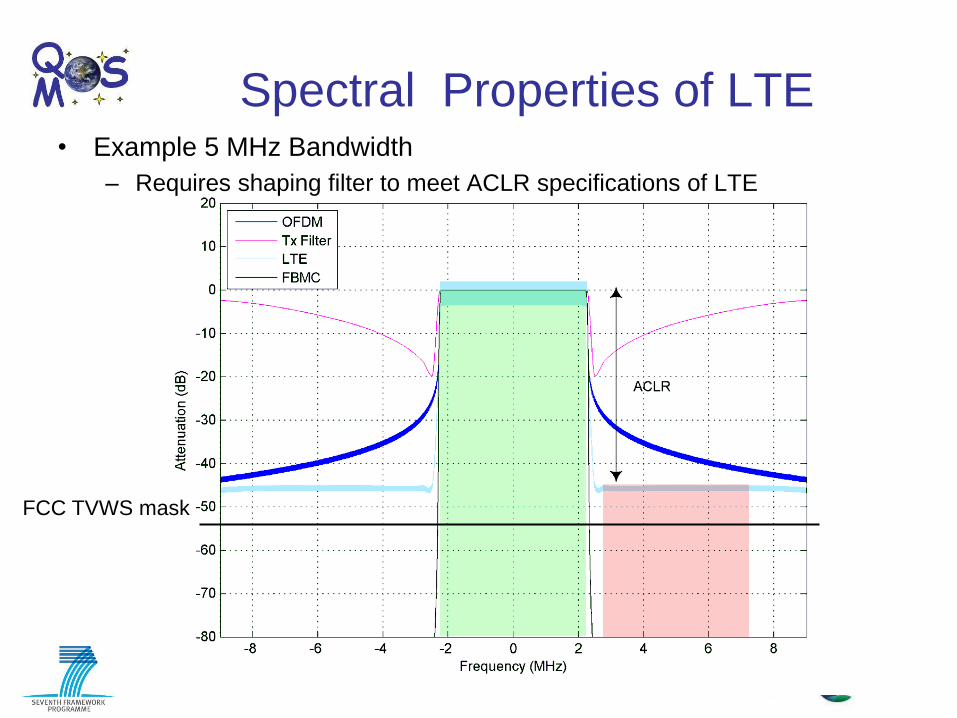
Spectral Properties of LTE and FBMC
• Example 5 MHz Bandwidth
– Requires shaping filter to meet ACLR specifications of LTE
Spectral Properties of LTE • Example 5 MHz Bandwidth
– Requires shaping filter to meet ACLR specifications of LTE
FCC TVWS mask
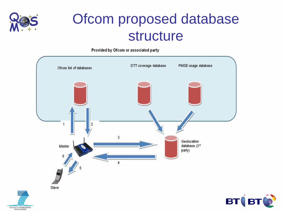
Ofcom proposed database
structure

Prototype TVWS availability database
Rural Scotland
London
Ipswich
• TVWS database provides – channels
– power levels
– duration of access
– directivity for any location UK

An exploitation from QoSMOS
- BT’s trials of broadband to ‘not-spots’
If D + E are too long (>5km) then
BB is not possible. Fibre to the Cabinet
will help only if D is not too long.
In many rural locations, premises are
connected via long copper lines
directly to the exchange. If this is
>5km then BB is not possible
Backhaul
Exchange House
15% of premises in the UK (2.75 million) cannot
receive broadband (2Mbit/s downlink). These are
called ‘not-spots’.

DSL bit-rates against distance (downlink)
0
10
20
30
40
50
60
70
80
90
100
0 1000 2000 3000 4000 5000
Distance (m)
Lin
e b
it-r
ate
(M
bit
/s)
ADSL
ADSL2+
VDSL2+
VDSL2 max rate = 200Mbit/s
ADSL uplink approx 450kbit/s (capped)
VDSL is approximately symmetrical
Little difference between them for > 4km line length

Distribution of ‘notspots’ direct distance
to nearest exchange
The average distance is
3km, which means the fixed
lines to many hotspots do not
take the shortest route.
Using TVWS, 2Mbit/s can be
delivered at 5km Non-LoS
and 8km LoS
>2Mbit/s Non-LoS >2Mbit/s LoS
So TVWS can potentially
solve the access problem
for a large proportion of not-spots

…correlate well with the areas of
Great Britain where TV White Space is
most available.
Example TV
Whitespace availability
The more rural areas of Great Britain, where
there are higher levels of poor broadband
performance due to line length….
Percentage of bad lines due to length
0 to 1%
1% to 2%
2% to 3%
3% to 5%
5% to 9%
9% to 11.4%
White = maximum
Red = minimum
TV whitespace spectrum versus notspot locations

TVWS CPE transceiver
to Ethernet
TVWS BS
Router
DSLAM
Backhaul
Ethernet
Up to 5km non line-of-sight
8km line-of-sight
The basic idea
To share wireless spectrum with
Digital TV Transmitters. This is
UHF between 470 – 790MHz
- Low diffraction and building penetration loss
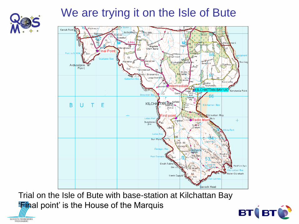
Trial on the Isle of Bute with base-station at Kilchattan Bay
‘Final point’ is the House of the Marquis
We are trying it on the Isle of Bute

Base-station antenna at Kilchatten Bay
exchange. Antenna up to 12m height
Backhaul antenna facing mainland
CPE antenna – same as TV antenna
Height 4m. At the House of the Marquis.
Test site on the Isle of Bute
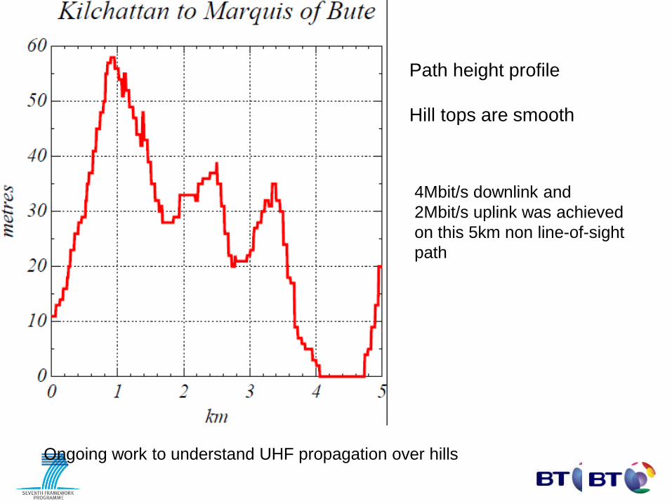
Path height profile
Hill tops are smooth
4Mbit/s downlink and
2Mbit/s uplink was achieved
on this 5km non line-of-sight
path
Ongoing work to understand UHF propagation over hills
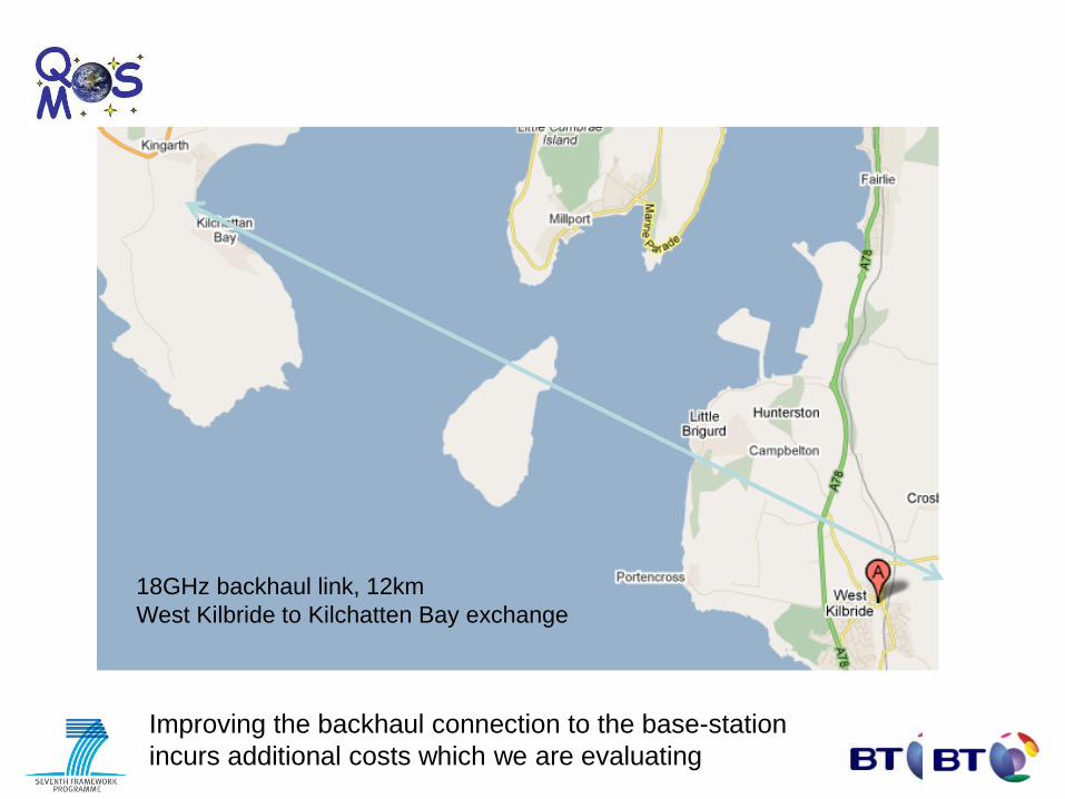
18GHz backhaul link, 12km
West Kilbride to Kilchatten Bay exchange
Improving the backhaul connection to the base-station
incurs additional costs which we are evaluating
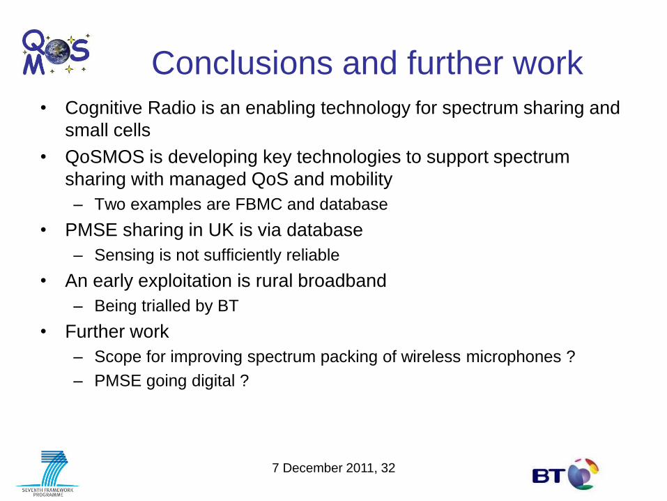
Conclusions and further work
• Cognitive Radio is an enabling technology for spectrum sharing and
small cells
• QoSMOS is developing key technologies to support spectrum
sharing with managed QoS and mobility
– Two examples are FBMC and database
• PMSE sharing in UK is via database
– Sensing is not sufficiently reliable
• An early exploitation is rural broadband
– Being trialled by BT
• Further work
– Scope for improving spectrum packing of wireless microphones ?
– PMSE going digital ?
7 December 2011, 32