Embed Size (px)
Citation preview

OVERVIEW OF FHR TECHNOLOGYPer F. Peterson
University of California, Berkeley
April 27, 2017
Meet the presenter
Per F. Peterson holds the William and Jean McCallum Floyd Chair
in the Department of Nuclear Engineering at the University of
California, Berkeley. He performs research related to high-
temperature fission energy systems, as well as studying topics
related to the safety and security of nuclear materials and waste
management. He participated in the development of the
Generation IV Roadmap in 2002 as a member of the Evaluation
Methodology Group, and co-chairs its Proliferation Resistance and
Physical Protection Working Group. His research in the 1990's
contributed to the development of the passive safety systems used
in the GE ESBWR and Westinghouse AP-1000 reactor designs.
Currently his research group focuses on heat transfer, fluid
mechanics, and regulation and licensing for advanced reactors,
including fluoride-salt cooled, high temperature reactors (FHRs).
Email: [email protected] 2
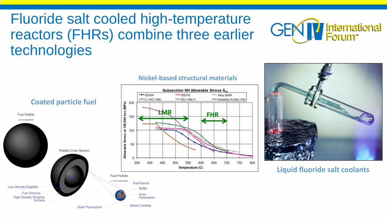
Fluoride salt cooled high-temperature reactors (FHRs) combine three earlier technologies
Liquid fluoride salt coolants
Coated particle fuel
FHRLMR
Nickel-based structural materials
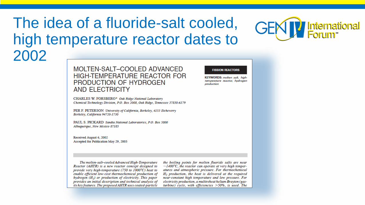
The idea of a fluoride-salt cooled, high temperature reactor dates to 2002

FHRs leverage experience and technology from multiple sourcesPassive Advanced Light Water Reactors
• Established licensing methodology for passive safety
• Integral Effects Test (IET) experiments, CSAU/PIRT
Sodium Fast Reactors• Design and structural materials for low pressure, high temperature
• Inert cover gas systems; thermal insulation and control, DRACS/RVACS
High Temperature Gas Reactors• TRISO fuel / functional containment
• Graphite and ceramic-fiber composite structural materials
Molten Salt Reactors• Fluoride salt chemistry control and thermophysical properties
Natural Gas Combined Cycle Plants (some types of FHRs)• Current dominant technology for new U.S. power conversion; adaptable to FHRs
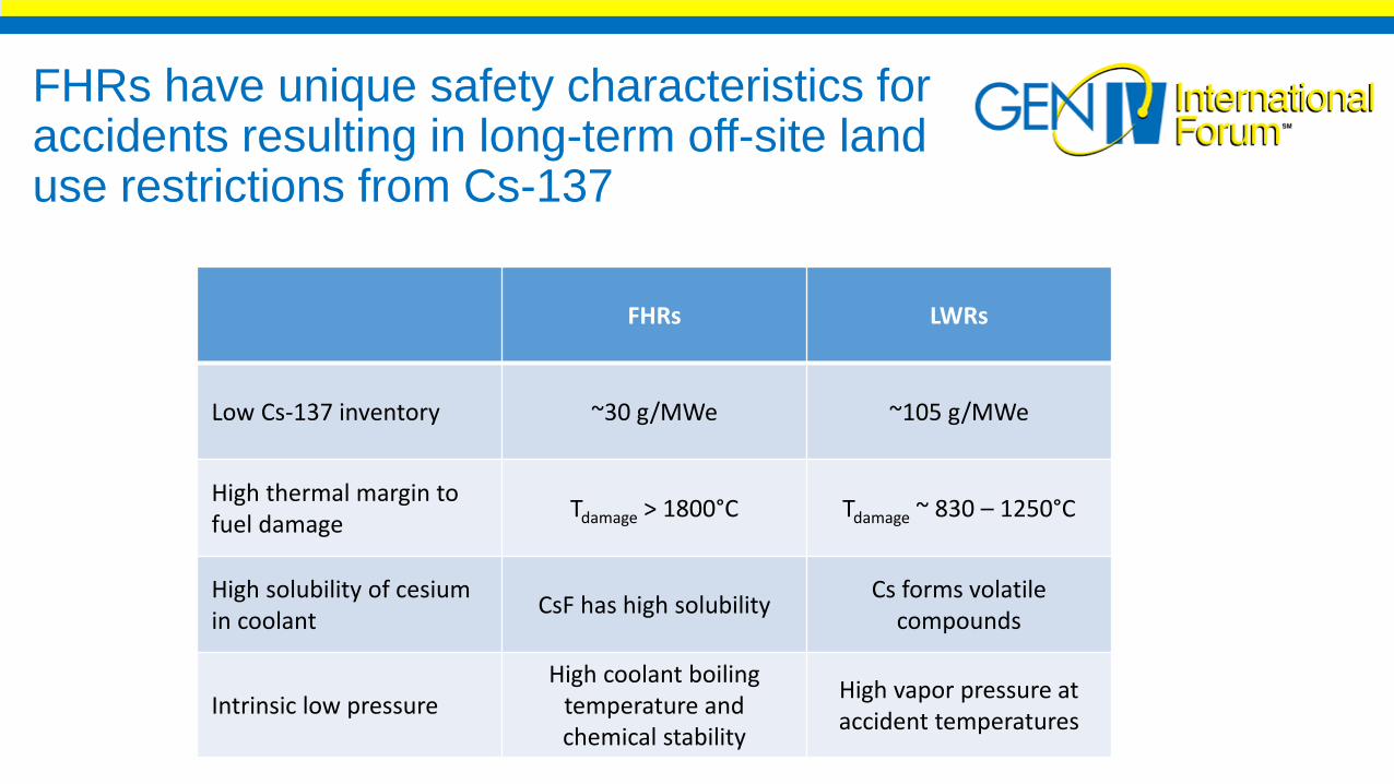
FHRs have unique safety characteristics for accidents resulting in long-term off-site land use restrictions from Cs-137
FHRs LWRs
Low Cs-137 inventory ~30 g/MWe ~105 g/MWe
High thermal margin to fuel damage
Tdamage > 1800°C Tdamage ~ 830 – 1250°C
High solubility of cesium in coolant
CsF has high solubilityCs forms volatile
compounds
Intrinsic low pressureHigh coolant boiling
temperature and chemical stability
High vapor pressure at accident temperatures
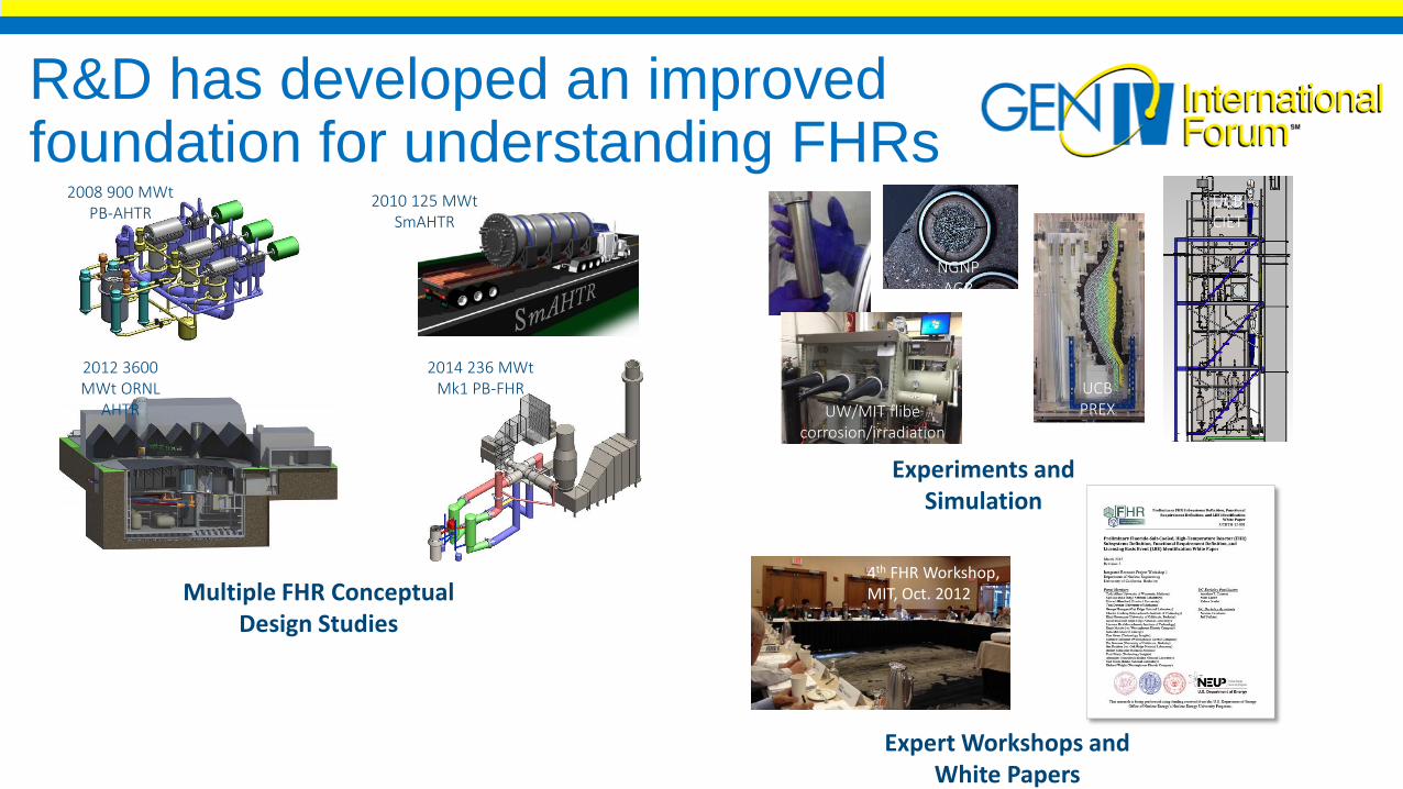
R&D has developed an improved foundation for understanding FHRs
Multiple FHR Conceptual Design Studies
Experiments and Simulation
Expert Workshops and White Papers
2008 900 MWtPB-AHTR
2010 125 MWtSmAHTR
2014 236 MWtMk1 PB-FHR
2012 3600 MWt ORNL
AHTR
4th FHR Workshop, MIT, Oct. 2012
UW/MIT flibecorrosion/irradiation
UCB CIET
UCB PREX
NGNP AGR

Studies for FHR fuels and materials are encouraging
• INL testing of NGNP TRISO fuel shows excellent fission product retention up to 1800°C
http://www.world-nuclear-news.org/ENF-Triso_fuel_triumphs_at_extreme_temperatures-2609137.html
• UW static corrosion tests show low corrosion rates for 316 SS and Alloy N in flibe at 700°C (1000 hr)
316SS in graphite, #2
316SS in graphite, #1
316SS in 316SS liner, #2
316SS in 316SS liner, #1
USDOE-Funded Integrated Research Projects have advanced the understanding of FHR technology
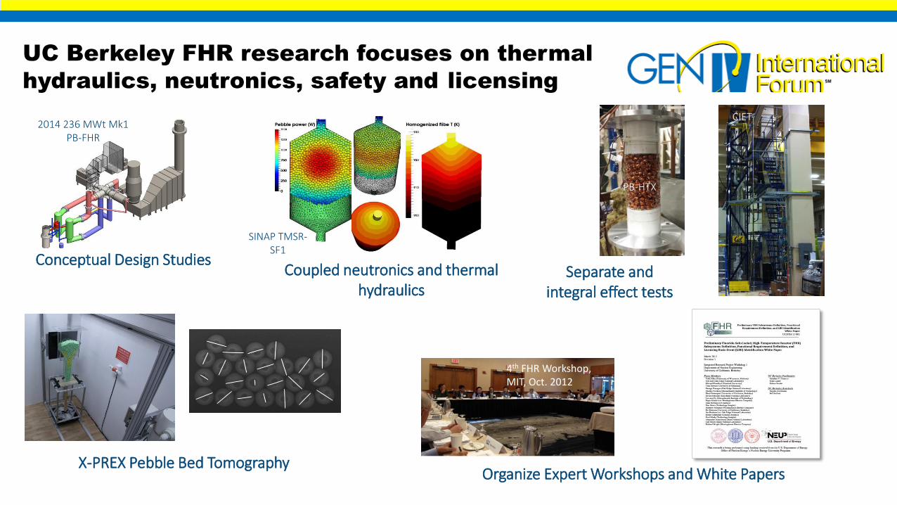
UC Berkeley FHR research focuses on thermal
hydraulics, neutronics, safety and licensing
Conceptual Design StudiesSeparate and
integral effect tests
Organize Expert Workshops and White Papers
2014 236 MWt Mk1 PB-FHR
4th FHR Workshop, MIT, Oct. 2012
CIET
PB-HTX
X-PREX Pebble Bed Tomography
SINAP TMSR-SF1
Coupled neutronics and thermal hydraulics
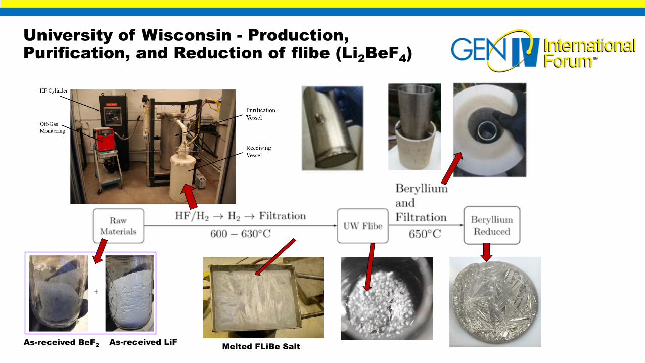
University of Wisconsin - Production, Purification, and Reduction of flibe (Li2BeF4)
As-received BeF2 As-received LiFMelted FLiBe Salt
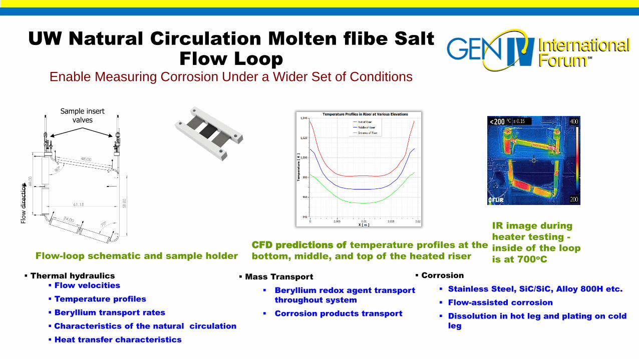
UW Natural Circulation Molten flibe Salt Flow Loop
Enable Measuring Corrosion Under a Wider Set of Conditions
Thermal hydraulics
Flow velocities
Temperature profiles
Beryllium transport rates
Characteristics of the natural circulation
Heat transfer characteristics
Mass Transport
Beryllium redox agent transport
throughout system
Corrosion products transport
Corrosion
Stainless Steel, SiC/SiC, Alloy 800H etc.
Flow-assisted corrosion
Dissolution in hot leg and plating on cold
leg
Flow-loop schematic and sample holder
Sample insert valves
Flo
w d
irec
tio
n
IR image during
heater testing -
inside of the loop
is at 700oC
CFD predictions of temperature profiles at the
bottom, middle, and top of the heated riser

In-Reactor Materials Testing for FHRs3rd FHR Irradiation in MITR (Fall 2016)
1000 hours at 700°C in enriched flibe
Graphite and C/C specimens (previously irradiated SiC, 316SS, Hastelloy-N, TRISO)

Separate Effects Test (SET) and Integral Effects Test (IET) for FHRs, using simulant fluids
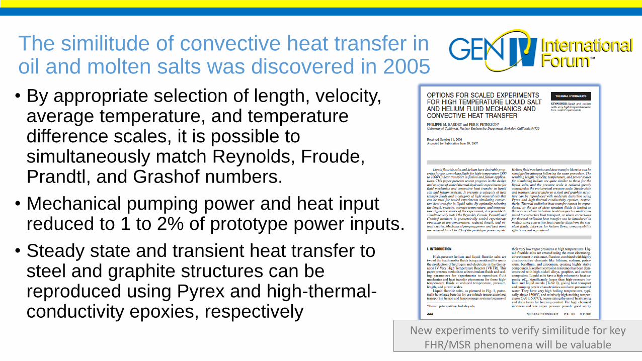
The similitude of convective heat transfer in oil and molten salts was discovered in 2005
• By appropriate selection of length, velocity, average temperature, and temperature difference scales, it is possible to simultaneously match Reynolds, Froude, Prandtl, and Grashof numbers.
• Mechanical pumping power and heat input reduced to 1 to 2% of prototype power inputs.
• Steady state and transient heat transfer to steel and graphite structures can be reproduced using Pyrex and high-thermal-conductivity epoxies, respectively
New experiments to verify similitude for key FHR/MSR phenomena will be valuable
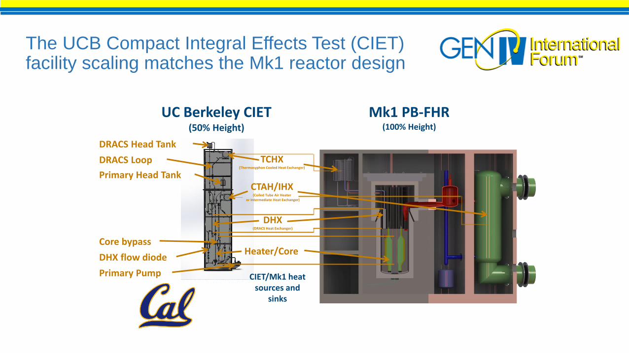
The UCB Compact Integral Effects Test (CIET) facility scaling matches the Mk1 reactor design
Heater/Core
DHX(DRACS Heat Exchanger)
CTAH/IHX(Coiled Tube Air Heater
or Intermediate Heat Exchanger)
TCHX(Thermosyphon Cooled Heat Exchanger)
UC Berkeley CIET(50% Height)
CIET/Mk1 heat sources and
sinks
Mk1 PB-FHR(100% Height)
DRACS Head Tank
DRACS Loop
Primary Head Tank
Core bypass
DHX flow diode
Primary Pump
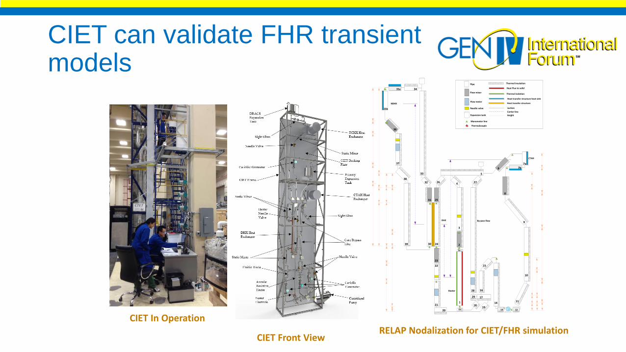
CIET can validate FHR transient models
Pipe
Flow mixer
Flow meter
Needle valve
Thermal insulation
Heat Flux to solid
Thermal isolation
Juction
Heat transfer structure heat sink
Heat transfer structure
CTAH
NDHX
Heater
DHX By-pass flow
2
3
5
4
6
7a
8
9
10
1114
15
16
17
20
21
23
24
25
26 27
28
30
31
32
33
34
35b
36
37
38
39
Expansion tank
181
Center line
Height
19
Manometer line
Thermalcouple
1213
22
1b
1a
29
7b
35a
RELAP Nodalization for CIET/FHR simulationCIET Front View
CIET In Operation
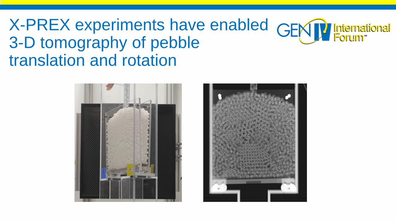
X-PREX experiments have enabled 3-D tomography of pebble translation and rotation
Mk1 PB-FHR Reference Design Overview
An example for FHR Design
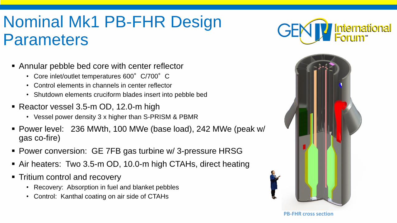
Nominal Mk1 PB-FHR Design Parameters
Annular pebble bed core with center reflector• Core inlet/outlet temperatures 600°C/700°C
• Control elements in channels in center reflector
• Shutdown elements cruciform blades insert into pebble bed
Reactor vessel 3.5-m OD, 12.0-m high• Vessel power density 3 x higher than S-PRISM & PBMR
Power level: 236 MWth, 100 MWe (base load), 242 MWe (peak w/ gas co-fire)
Power conversion: GE 7FB gas turbine w/ 3-pressure HRSG
Air heaters: Two 3.5-m OD, 10.0-m high CTAHs, direct heating
Tritium control and recovery• Recovery: Absorption in fuel and blanket pebbles
• Control: Kanthal coating on air side of CTAHs
PB-FHR cross section
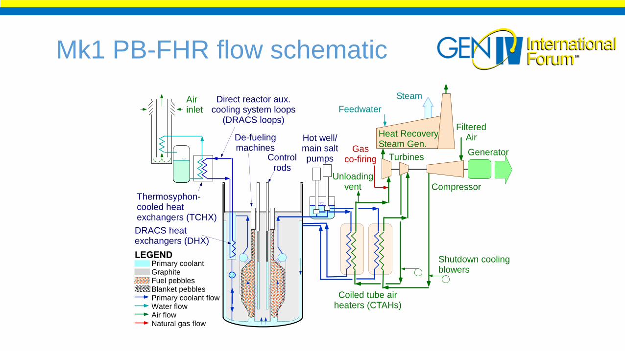
Mk1 PB-FHR flow schematic
Compressor
Generator
FilteredAir
Turbines
Heat RecoverySteam Gen.
Unloadingvent
Gasco-firing
Hot well/main saltpumps
Shutdown coolingblowers
Coiled tube airheaters (CTAHs)
Airinlet
Thermosyphon-cooled heatexchangers (TCHX)
Direct reactor aux.cooling system loops
(DRACS loops)
DRACS heatexchangers (DHX)
Controlrods
De-fuelingmachines
Primary coolantGraphiteFuel pebblesBlanket pebblesPrimary coolant flowWater flowAir flowNatural gas flow
LEGEND
Feedwater
Steam
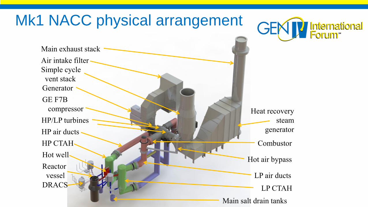
Mk1 NACC physical arrangement
Heat recovery
steam
generator
Simple cycle
vent stack
Main exhaust stack
GE F7B
compressor
Air intake filter
Generator
HP air ducts
HP CTAH
Main salt drain tanks
LP CTAH
LP air ducts
Hot air bypassReactor
vessel
Hot well
Combustor
HP/LP turbines
DRACS
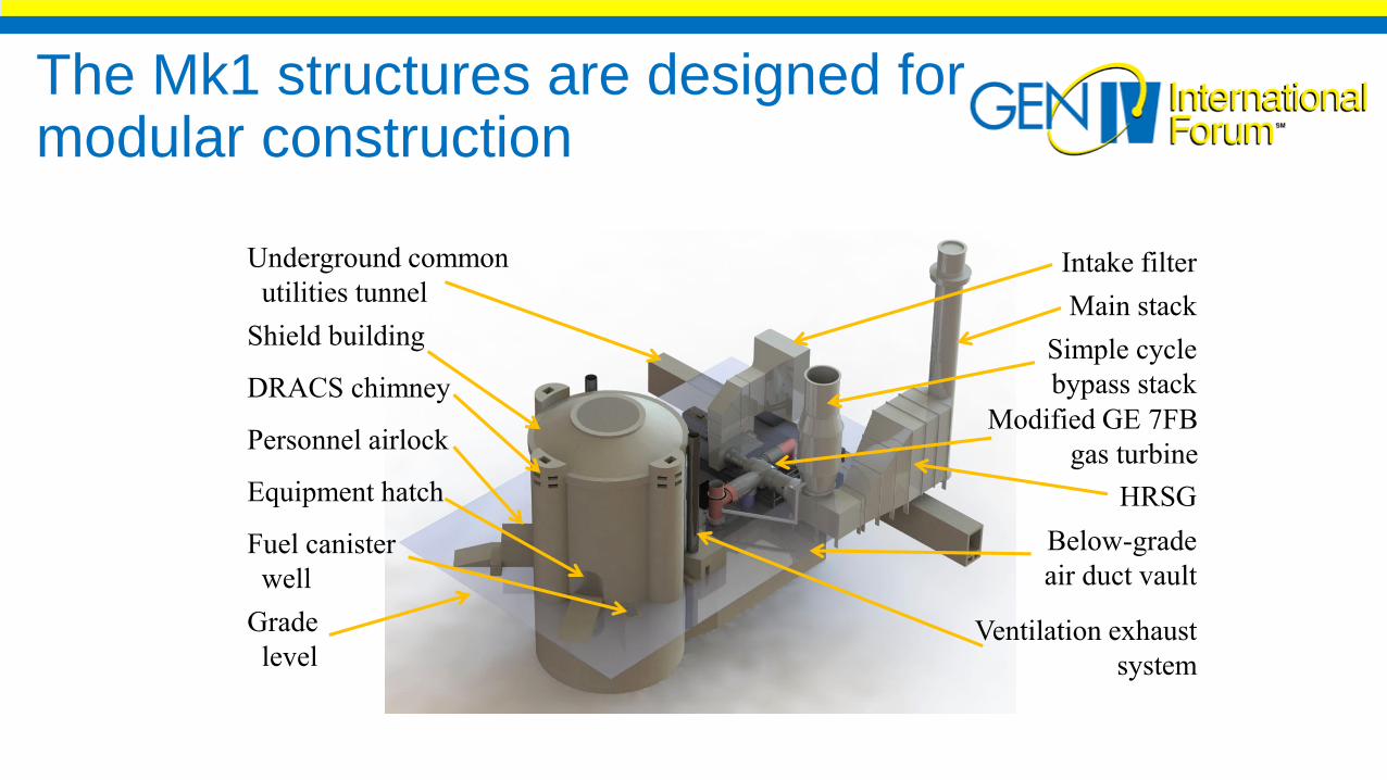
The Mk1 structures are designed for modular construction
Underground common
utilities tunnel
Shield building
DRACS chimney
Personnel airlock
Equipment hatch
Fuel canister
well
Grade
level
Intake filter
Main stack
Simple cycle
bypass stack
HRSG
Modified GE 7FB
gas turbine
Below-grade
air duct vault
Ventilation exhaust
system
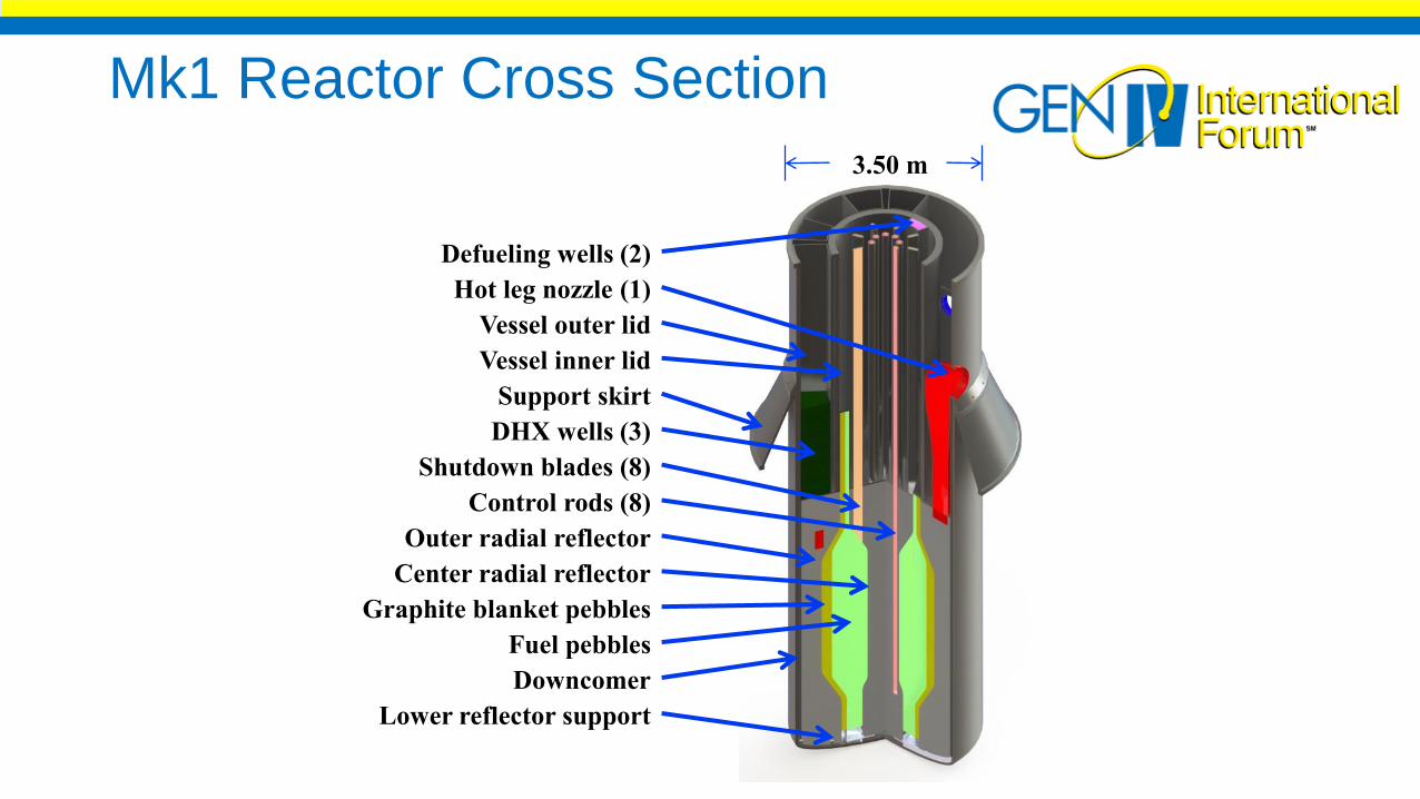
Mk1 Reactor Cross Section
Defueling wells (2)
3.50 m
Hot leg nozzle (1)
Vessel outer lid
Vessel inner lid
Support skirt
DHX wells (3)
Shutdown blades (8)
Control rods (8)
Outer radial reflector
Center radial reflector
Graphite blanket pebbles
Fuel pebbles
Downcomer
Lower reflector support
Modular Construction for Small Modular Reactors: Concepts for reduced construction costs for multi-module reactor sites

The Mk1 uses steel-plate composite modular construction
Vogtle Unit 3 shield building wall panels, May 2014
Summer Unit 2 CA20 Transported from MABCA20 being set in place by heavy crane

The Mk1 design uses 10 primary structural modules
Base mat
SB1 AD1
SB2 AD2
SB3AD3
SB5
SB7a-gSB6
SB4
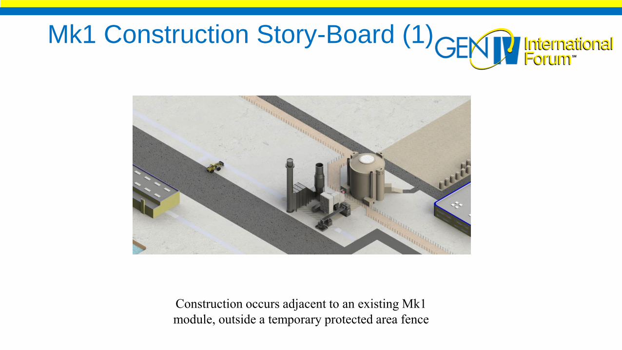
Mk1 Construction Story-Board (1)
Construction occurs adjacent to an existing Mk1
module, outside a temporary protected area fence
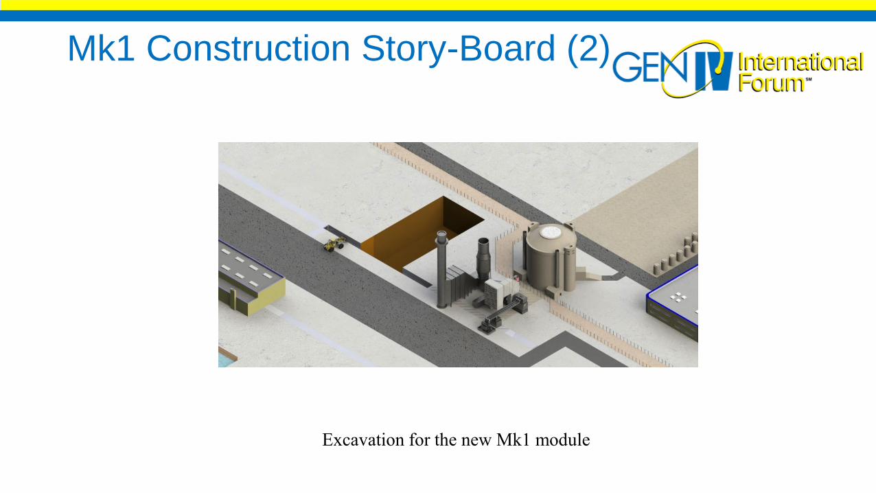
Mk1 Construction Story-Board (2)
Excavation for the new Mk1 module
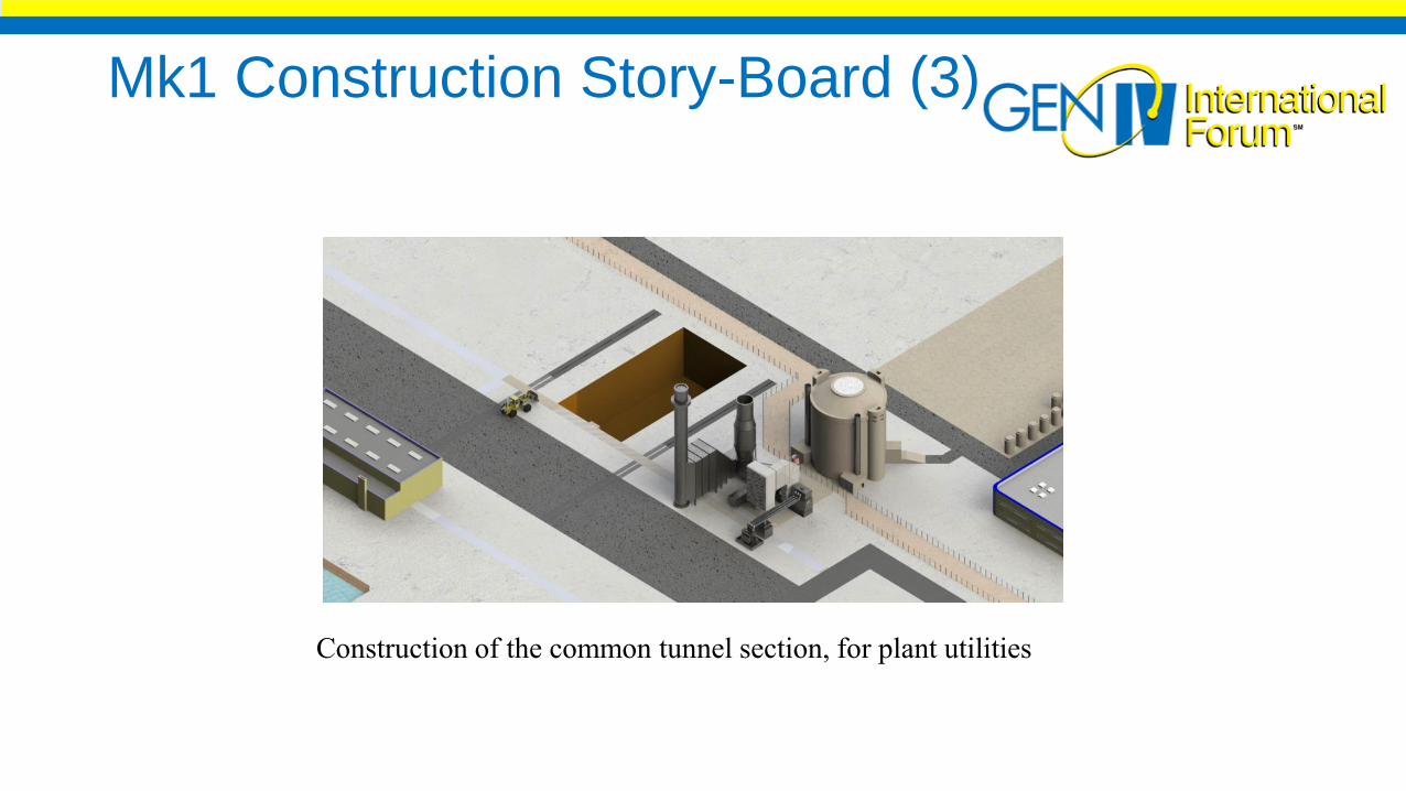
Mk1 Construction Story-Board (3)
Construction of the common tunnel section, for plant utilities

Mk1 Construction Story-Board (4)
Construction lift tower
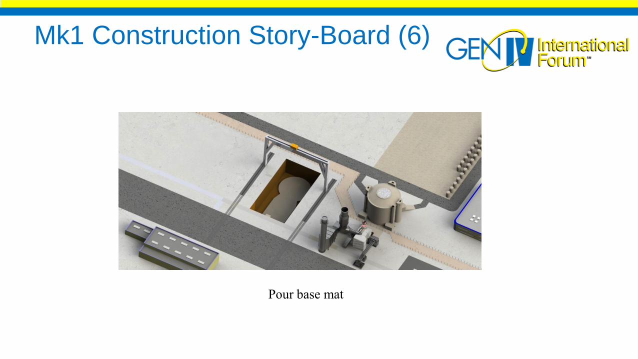
Mk1 Construction Story-Board (6)
Pour base mat
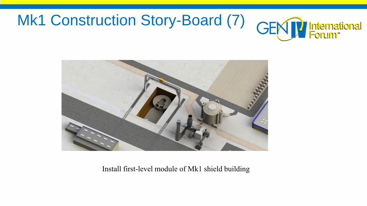
Mk1 Construction Story-Board (7)
Install first-level module of Mk1 shield building

Mk1 Construction Story-Board (8)
Install second-level module of Mk1 shield building
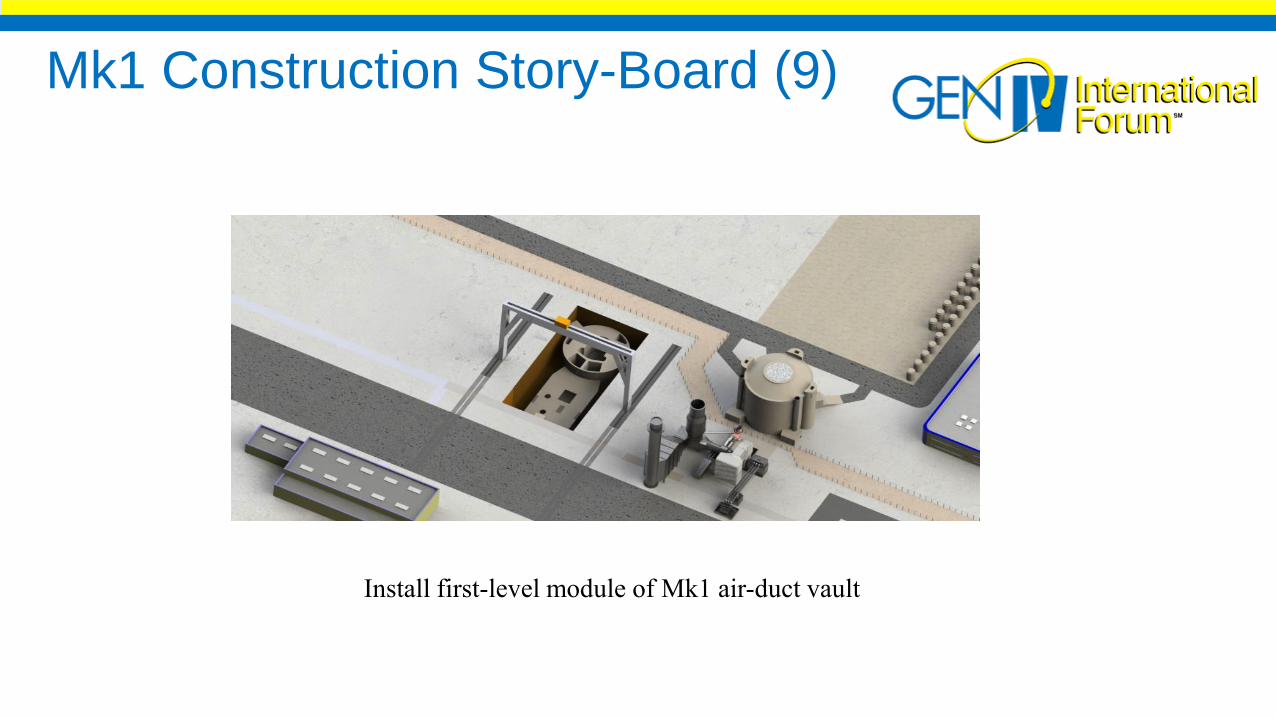
Mk1 Construction Story-Board (9)
Install first-level module of Mk1 air-duct vault
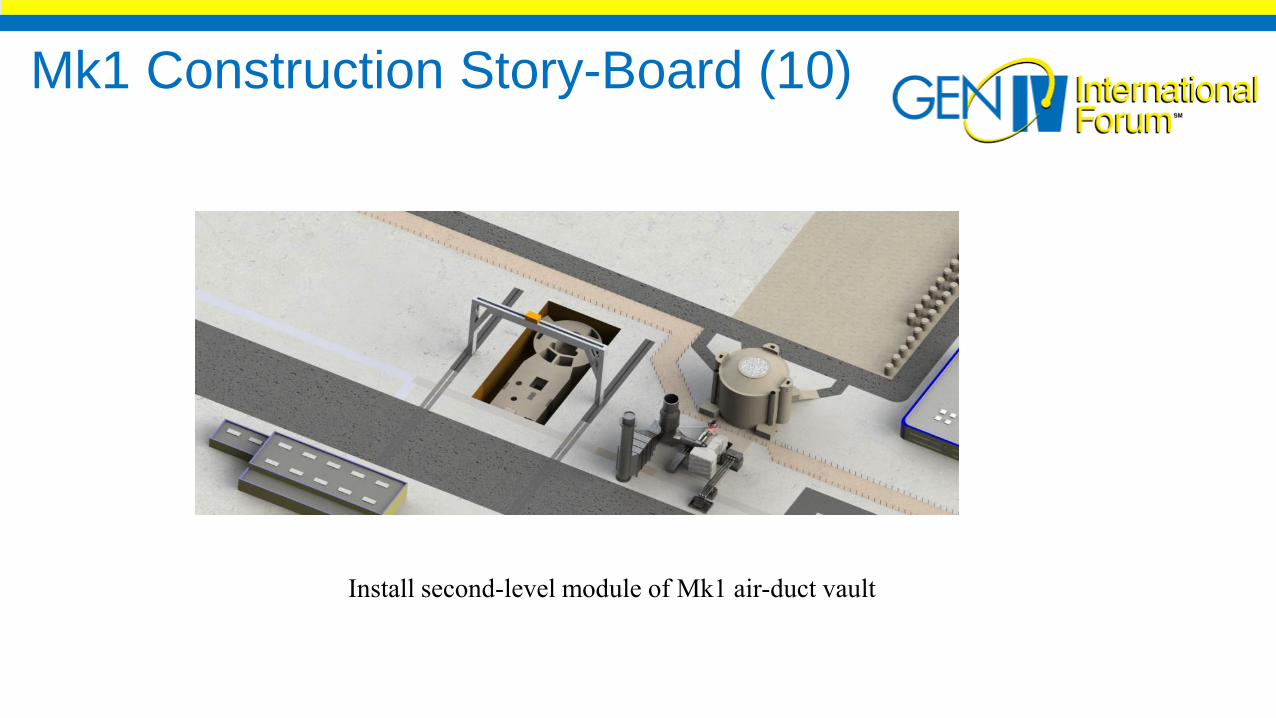
Mk1 Construction Story-Board (10)
Install second-level module of Mk1 air-duct vault
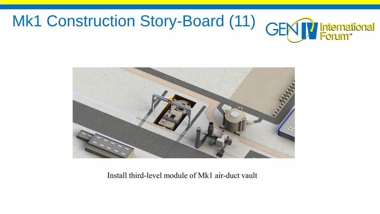
Mk1 Construction Story-Board (11)
Install third-level module of Mk1 air-duct vault

Mk1 Construction Story-Board (12)
Install Mk1 reactor cavity module

Mk1 Construction Story-Board (13)
Install Mk1 CTAH and I.O. pipes
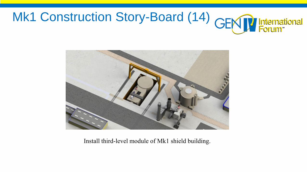
Mk1 Construction Story-Board (14)
Install third-level module of Mk1 shield building.

Mk1 Construction Story-Board (15)
Back fill below-grade structures to grade level
Excavation for the next unit may begin

Mk1 Construction Story-Board (16)
Install main shield building cylinder.
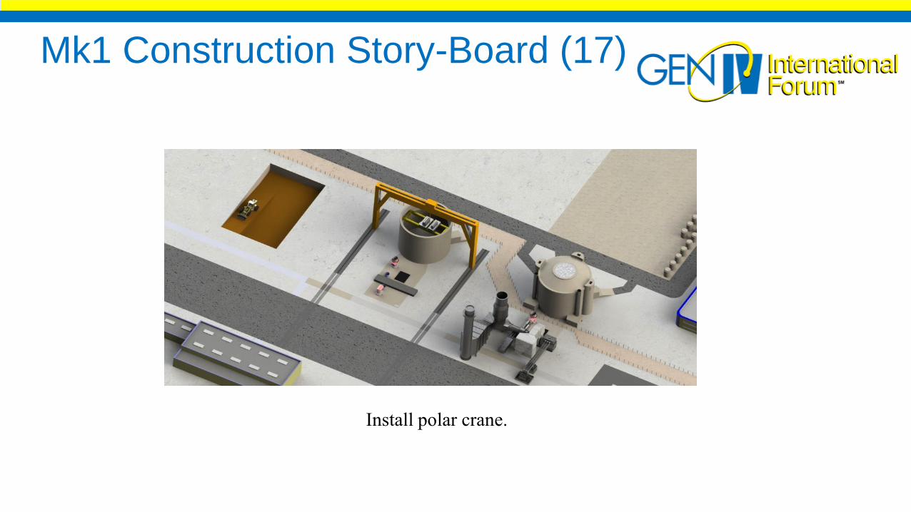
Mk1 Construction Story-Board (17)
Install polar crane.

Mk1 Construction Story-Board (18)
Install shield building roof.

Mk1 Construction Story-Board (19)
Install DRACS chimneys and ventilation filter and exhaust enclosures.
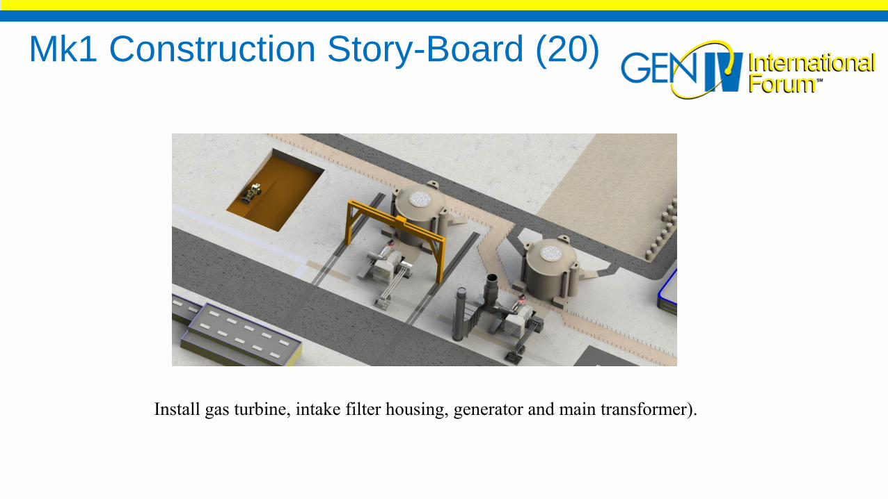
Mk1 Construction Story-Board (20)
Install gas turbine, intake filter housing, generator and main transformer).
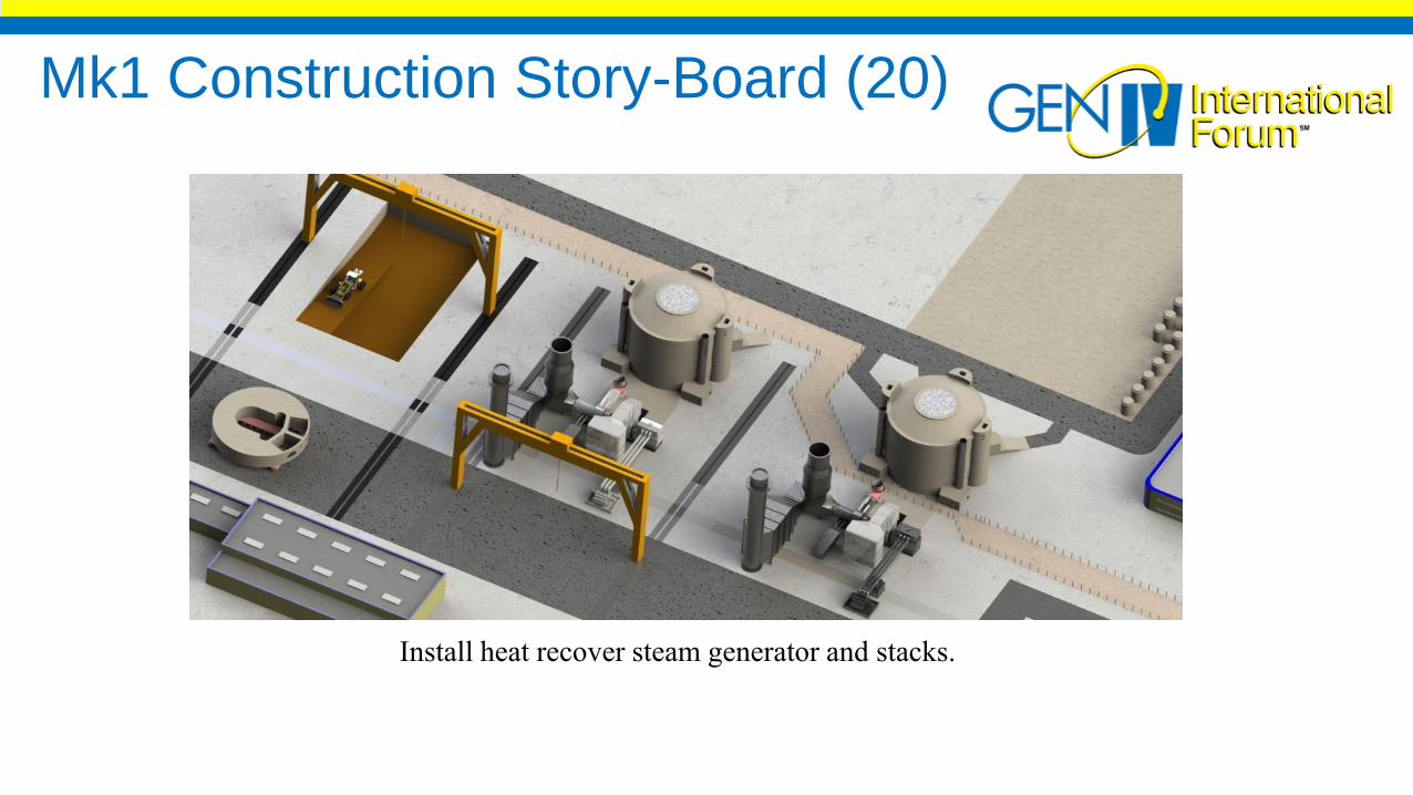
Mk1 Construction Story-Board (20)
Install heat recover steam generator and stacks.
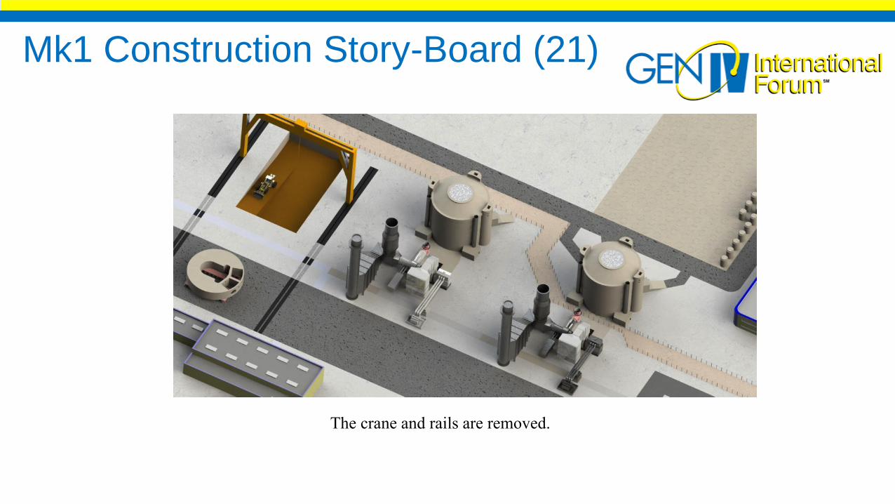
Mk1 Construction Story-Board (21)
The crane and rails are removed.
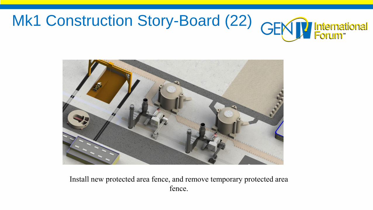
Mk1 Construction Story-Board (22)
Install new protected area fence, and remove temporary protected area
fence.
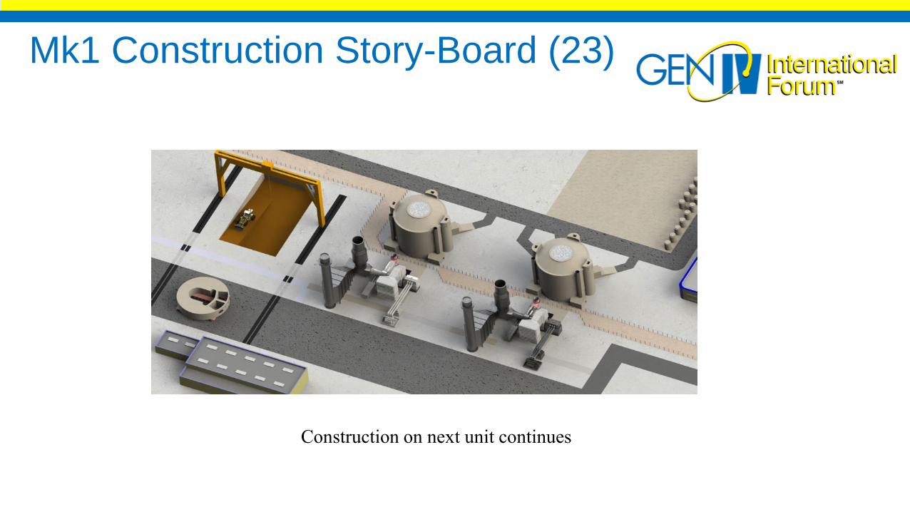
Mk1 Construction Story-Board (23)
Construction on next unit continues
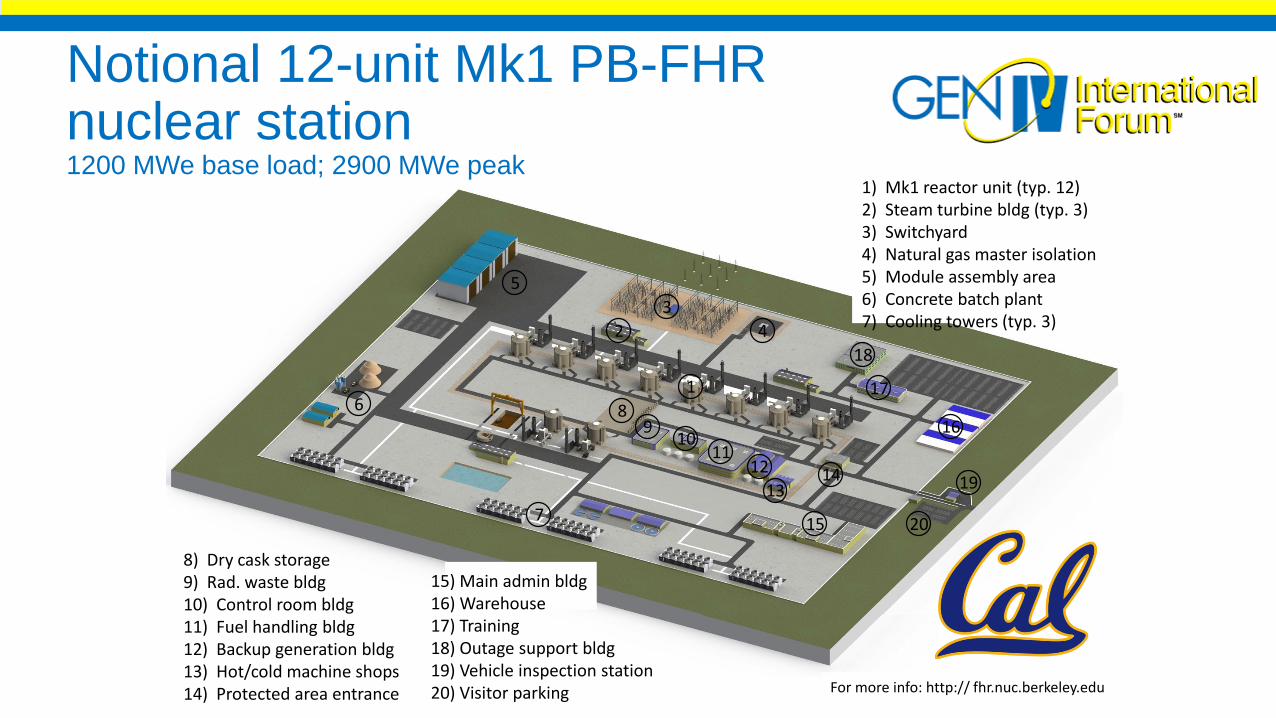
Notional 12-unit Mk1 PB-FHR nuclear station1200 MWe base load; 2900 MWe peak
1) Mk1 reactor unit (typ. 12)2) Steam turbine bldg (typ. 3)3) Switchyard4) Natural gas master isolation5) Module assembly area6) Concrete batch plant7) Cooling towers (typ. 3)
8) Dry cask storage9) Rad. waste bldg10) Control room bldg11) Fuel handling bldg12) Backup generation bldg13) Hot/cold machine shops14) Protected area entrance
20
19
18
16
15
1413
1211
109
8
7
6
5
4
3
2
1
15) Main admin bldg16) Warehouse17) Training18) Outage support bldg19) Vehicle inspection station20) Visitor parking
17
For more info: http:// fhr.nuc.berkeley.edu

UPCOMING WEBINARS
23 May 2017 Molten Salt Reactor Dr. Elsa Merle, CEA, USA
12 June 2017 Lead Fast Reactor Prof. Craig Smith, US Naval Graduate School, USA
18 July 2017 Thorium Fuel Cycle Dr. Franco-Michel Sendis, NEA/OECD