Embed Size (px)
Citation preview

FHR Functional Requirements and LBE Identification White Paper
Integrated Research Project Workshop 1
Fluoride-Salt-Cooled, High-Temperature Reactor (FHR) Subsystems Definition, Functional Requirement Definition, and Licensing Basis Event
(LBE) Identification White Paper
Panel Members Todd Allen (University of Wisconsin, Madison) Syd Ball (Oak Ridge National Laboratory) Edward Blandford (Stanford University) Thomas Downar (University of Michigan) George Flanagan (Oak Ridge National Laboratory) Charles Forsberg (Massachusetts Institute of Technology) Ehud Greenspan (University of California, Berkeley) David Holcomb (Oak Ridge National Laboratory) Lin-Wen Hu (Massachusetts Institute of Technology) Regis Matzie (ret. Westinghouse Electric Company)
John McGaha (ret. Entergy) Dan Mears (Technology Insights) Matthew Memmot (Westinghouse Electric Company) Per Peterson (University of California, Berkeley) James Rushton (ret. Oak Ridge National Laboratory) Robert Schleicher (General Atomics) Fred Silady (Technology Insights) Alexander Stanculescu (Idaho National Laboratory) Carl Stoots (Idaho National Laboratory) Richard Wright (Westinghouse Electric Company)
UC Berkeley Facilitators Anselmo Cisneros Michael Laufer Raluca Scarlat
UC Berkeley Assistants Nicolas Zweibaum Jeffrey Seifried
UCBTH-12-001 Final
August 2013 Department of Nuclear Engineering University of California, Berkeley
This research is being performed using funding received from the U.S. Department of Energy
Office of Nuclear Energy’s Nuclear Energy University Programs.

FHR Functional Requirements and LBE Identification White Paper 2 | 104
Preamble
The University of California, Berkeley; Massachusetts Institute of Technology; and University of Wisconsin, Madison, hosted a series of four workshops during 2012 under a U.S. Department of Energy-sponsored Integrated Research Project (IRP) to review technical and licensing issues for fluoride-salt-cooled, high-temperature reactors (FHRs). The focus of the first workshop was to identify key development goals for FHRs, including the major technical characteristics that differentiate FHRs from other power reactor technologies, the major systems and subsystems expected to be used in FHRs, high-level functional requirements for these systems and subsystems, and licensing basis events (LBEs) that should be considered in FHR design and licensing.
The four workshops are a central element of developing a FHR preliminary conceptual design report to be completed in 2014. This first white paper focuses on material covered by the first workshop and is divided into four chapters. The first chapter provides an overview of the IRP and FHR technology, as well as a high-level discussion of the FHR licensing strategy. The second chapter lays out the FHR system decomposition and the Safety Design Criteria. The third chapter reviews the candidate materials, including fuels, structural materials, and fluids that would be used in FHRs. The fourth chapter focuses on the selection of FHR LBEs and first identifies the existing U.S. Nuclear Regulatory Commission precedent for LBE identification for existing light-water reactor technology. The white paper provides a preliminary set of bounding LBEs and a detailed discussion on the LBE identification logic. Appendix A identifies the major system and subsystem functional requirements for FHRs.
The comments of the experts attending the workshop were also integrated into this white paper. The IRP sincerely appreciates the input of all of the experts who attended and contributed to this workshop, as well as the hard work of the graduate students and postdoctoral scholars who organized the workshop, facilitated the sessions, and drafted the major sections of this white paper based on their research and the review and input of the workshop experts.

FHR Functional Requirements and LBE Identification White Paper 3 | 104
Dedication
The white papers developed during the series of four FHR workshops, including this white paper, are dedicated to Dr. L. Daniel Mears, who passed away on May 31, 2013. Dan Mears served on the Advisory Panel for the FHR Integrated Research Project, and provided key advice to the project including participating on its expert panel for the first FHR workshop. During his career, which started in 1969 at General Atomics, he made major contributions to the advancement of high temperature reactor technology. In 1992 he served as the founder and president of Technology Insights. The work performed at Technology Insights to develop the basis for licensing of gas cooled high temperature reactors provides the foundation for the FHR safety assessment and licensing approach described in this white paper.

FHR Functional Requirements and LBE Identification White Paper 4 | 104
Executive Summary
Fluoride-salt-cooled, high-temperature reactor (FHR) technology uses a novel combination of coated-particle fuels, fluoride salt coolant, and a low-pressure, high-temperature primary system to deliver heat in the temperature range from 600°C to 700°C or higher. This white paper provides a review of the results from a two-day expert workshop held in Berkeley, California, in February 2012 to review and discuss functional requirements and licensing strategies for this new technology.
In the ten years of research since the FHR concept was first proposed, multiple conceptual designs have been generated and a basic understanding of key reactor design approaches has emerged. Based upon this earlier research, this white paper proposes a system decomposition scheme, presents key FHR constituents and materials selection options, and identifies functional requirements for the key subsystems of FHRs. A set of six safety design criteria (SDC) are proposed as the top level safety requirements for FHRs, and defense in depth strategies for meeting each of the requirements are suggested. Likewise, the white paper proposes an initial set of licensing basis events (LBEs) and system operating states to be used in developing safety system designs and models for FHRs.
The workshop experts reached general agreement that the U.S. Nuclear Regulatory Commission licensing frameworks, which have been developed for passive light water reactors (LWRs), liquid metal reactors (LMRs), and high-temperature, gas-cooled reactors can be adapted successfully to license FHRs. FHRs have important differences from these other reactor technologies, particularly because of the very large thermal margins of FHR fuel during design basis transients and accidents and the thermophysical characteristics of its low-volatility, chemically stable coolant. For FHR design and safety analysis, six high-level SDC based on earlier work by the Next Generation Nuclear Plant (NGNP) and Pebble Bed Modular Reactor projects provide an appropriate framework to guide the design of safety-relevant FHR systems, structures, and components:
SDC 1: Maintain control of radionuclides
SDC 2: Control heat generation (reactivity)
SDC 3: Control heat removal and addition
SDC 4: Control primary coolant inventory
SDC 5: Maintain core and reactor vessel geometry
SDC 6: Maintain reactor building structural integrity.
The workshop experts reviewed and discussed high-level FHR design strategies to meet these six SDC. Upcoming work by a new committee of the American Nuclear Society (ANS) to create a safety standard for FHRs, ANS 20.1, will provide the basis to develop consensus-based FHR-specific General Design Criteria (GDC) derived from existing LWR-specific GDC, to be used in licensing reviews.

FHR Functional Requirements and LBE Identification White Paper 5 | 104
The major attributes of FHRs emerge from the combination of fuel, materials, and coolants used in these systems. The workshop experts reviewed the major issues associated with further development of fuels and materials for use in FHRs. This review identified multiple areas where the NGNP and LMR programs have developed key capabilities relevant to FHRs. In particular, experts concluded that the U.S. programs to develop coated-particle fuels for the NGNP, to develop graphite and ceramic composite materials and ASME code design rules for their use in the NGNP, and to develop high-temperature metallic materials for use in the NGNP and LMRs are of critical importance to the development of an FHR test reactor (FHTR) and a commercial prototype. FHR materials and fuels was the topic of the third FHR workshop, and is discussed in much greater detail in the third workshop white paper.
The workshop experts also reviewed and discussed major systems and subsystems that will be needed for FHRs and used their collective expertise to identify key functional requirements for these systems and subsystems. Appendix A summarizes results from this discussion. Experts at the workshop emphasized the importance for the IRP to develop a systematic method to document functional requirements and other design bases information as a part of its work to develop pre-conceptual designs for an FHTR and a commercial prototype.
Safety assessment of nuclear reactors requires a systematic effort to identify the range of potential events, and their frequencies, that have the potential to challenge the safety of the reactor. The experts reviewed and discussed the existing regulatory framework to identify LBEs and the application of probabilistic risk assessment to identify and categorize events. Participants generally agreed that the existing approaches for identifying anticipated operational occurrences and design basis events can be readily adapted to identify these events for FHRs, and that designers should select and evaluate a representative subset of these events in the pre-conceptual design phase and facilitate the development and validation of safety analysis codes and methods for FHRs (a major topic of the second workshop). The discussion about beyond design basis events (BDBEs) yielded guidance but also concluded that the approach to identifying BDBEs and assessing the ability of an FHR to respond to and mitigate consequences of BDBEs, requires further development, particularly because the high thermal margins of FHR fuel suggest that these reactors can be designed to have very robust and effective response to BDBEs even when they result in extensive plant damage.
This first workshop and white paper develop an overall framework to guide the design and licensing of future FHRs. Workshop participants also emphasized the importance of developing economic and cost models to guide design decisions and optimization.

FHR Functional Requirements and LBE Identification White Paper 6 | 104
Contents
1 Introduction .......................................................................................................................... 13 1.1 White Paper Outline ................................................................................................................... 16 1.2 Historical Perspective on Liquid Fluoride-Salt Reactor Development .................................. 17
1.2.1 FHR Reactor Development .................................................................................................... 18 1.2.2 FHR Reactor Characteristics .................................................................................................. 19
1.3 Design Strategy for FHR Development ..................................................................................... 20 1.3.1 Programmatic Requirements .................................................................................................. 21 1.3.2 FHR Functional, Operational, and Technical Requirements ................................................. 21 1.3.3 FHR Licensing Strategy ......................................................................................................... 23
2 FHR SDC and System Decomposition ................................................................................ 27 2.1 FHR System Decomposition ....................................................................................................... 29 2.2 SDC 1 - Maintain Control of Radionuclides ............................................................................. 31
2.2.1 Fuel Source Term ................................................................................................................... 32 2.2.2 Tritium and Other Circulating Activity ................................................................................. 32
2.3 SDC 2 – Control Heat Generation (Reactivity) ........................................................................ 34 2.3.1 Important Reactivity Transients ............................................................................................. 35
2.4 SDC 3 – Control Heat Removal and Addition .......................................................................... 35 2.4.1 Overheating Transients .......................................................................................................... 36 2.4.2 Overcooling Transients .......................................................................................................... 38
2.5 SDC 4 – Control Primary Coolant Inventory ........................................................................... 38 2.6 SDC 5 – Maintain Core and Reactor Vessel Geometry ........................................................... 40 2.7 SDC 6 – Maintain Reactor Building Structural Integrity ....................................................... 42
3 FHR Materials Selection ...................................................................................................... 43 3.1 FHR Fuel ...................................................................................................................................... 43 3.2 FHR Fluids ................................................................................................................................... 45
3.2.1 Primary Coolant ..................................................................................................................... 46 3.2.2 Intermediate Coolant Options ................................................................................................ 47 3.2.3 DRACS Coolant..................................................................................................................... 47 3.2.4 Buffer Salt .............................................................................................................................. 48 3.2.5 Heat Sinks .............................................................................................................................. 48 3.2.6 Gases ...................................................................................................................................... 48
3.3 FHR Structural Materials .......................................................................................................... 49 3.3.1 Metallic Structures and Components ..................................................................................... 49 3.3.2 Ceramic Structures and Components ..................................................................................... 52 3.3.3 Building Structures ................................................................................................................ 53
4 Selection of FHR Licensing Basis Events ........................................................................... 55 4.1 Regulatory Foundation ............................................................................................................... 55
4.1.1 NRC Guidance on the Use of Probabilistic Risk Assessment ............................................... 55 4.1.2 NRC Experience for Advanced Reactors ............................................................................... 56 4.1.3 Special Considerations for FHR TLRC ................................................................................. 57
4.2 FHR Operating Modes and States ............................................................................................. 58 4.2.1 Power Operation .................................................................................................................... 59 4.2.2 Operational Standby ............................................................................................................... 60 4.2.3 Standby .................................................................................................................................. 60 4.2.4 Shutdown ............................................................................................................................... 60

FHR Functional Requirements and LBE Identification White Paper 7 | 104
4.2.5 Fueled Maintenance ............................................................................................................... 60 4.2.6 Defueled Maintenance ........................................................................................................... 61
4.3 FHR LBE Selection Approach ................................................................................................... 61 4.3.1 LBE Selection Process Overview .......................................................................................... 61 4.3.2 Risk-Informed Approach for AOOs and DBEs ..................................................................... 62 4.3.3 Bounding Events Approach for BDBEs ................................................................................ 67 4.3.4 Lessons from Fukushima for Severe External BDBEs .......................................................... 71 4.3.5 Iterative Approach for Design and System Reliability Requirements ................................... 72
References .................................................................................................................................... 74
Appendix A: FHR Subsystem Functional Requirements..................................................... 78 A.1 Functional Requirements for the Reactor System ..................................................................... 79
A.1.1 Functional Requirements for the Fuel Subsystem .................................................................. 81 A.1.2 Functional Requirements for the Primary Coolant Subsystem .............................................. 85 A.1.3 Functional Requirements for the Primary Pump Subsystem .................................................. 87 A.1.4 Functional Requirements for the Graphite Structures Subsystem ........................................... 88 A.1.5 Functional Requirements for the Core Barrel and Downcomer Subsystem ........................... 89 A.1.6 Functional Requirements for the Upper Core Support Structures Subsystem ....................... 90
A.2 Functional Requirements for the Reactivity Control System ................................................... 91 A.3 Functional Requirements for the Direct Reactor Auxiliary Cooling System (DRACS) ........ 93 A.4 Functional Requirements for Reactor Vessel and Reactor Cavity........................................... 95 A.5 Functional Requirements for the Intermediate Loop................................................................ 97 A.6 Functional Requirements for the Main Support Systems ....................................................... 100 A.7 Functional Requirements for the Power Units ......................................................................... 103 A.8 Functional Requirements for the Balance of Plant .................................................................. 104

FHR Functional Requirements and LBE Identification White Paper 8 | 104
List of Figures
Figure 1-1. IRP Structure, Illustrating Workshop Rationale and Key IRP Objectives (this white paper focuses on the first workshop) .......................................................... 14
Figure 1-2. Preliminary Conceptual System Design of the PB-AHTR 900-MWth Reactor (left) and a 125-MWth SmAHTR Reactor Module (right) ................................... 19
Figure 1-3. Major FHR Subsystems ........................................................................................ 20 Figure 1-4. FHR Plant Architecture Using the PASSC Convention, Developed by the NGNP
Program (Collins et al. 2008) ................................................................................ 22 Figure 1-5. Use of Plant Architecture to Devise Both Programmatic Requirements and
Functional, Operational, and Technical Requirements [adapted from the NGNP program (Collins et al. 2008)] ............................................................................... 23
Figure 1-6. FHR-Specific SDC Categories and FHR Detailed Safety Functions ................... 25 Figure 2-1. FHR System Decomposition Paradigm ................................................................ 29 Figure 2-2. HVAC Zones in an FHR Reactor Building: Reactor Cavity (yellow), Filtered
Confinement (green), and External Event Shell (blue/purple) (Fei et al. 2008) ... 33 Figure 3-1. FHR Pebble Fuel, Which Uses an Inert, Low-Density Center Graphite Kernel to
Control Buoyancy and Reduce the Peak Fuel Temperature ................................. 45 Figure 3-2. ASME Code-Allowable Stresses for Several Structural Materials (Sims and
Nestell 2012) ......................................................................................................... 51 Figure 3-3. A Typical Steel-Concrete Structural Module Used in the AP-1000 ..................... 54 Figure 4-1. FHR Operation Modes from Shutdown to Normal Power Operation and the Plant
Actions Required for Transition Between Them .................................................. 59 Figure 4-2. Frequency-Consequence Chart from NGNP Program with TLRC Limits (Idaho
National Laboratory 2010b) .................................................................................. 66 Figure 4-3. Sample FHR Event Tree for Loss of the PCU ...................................................... 67 Figure 4-4. Modified Event Tree for Loss of the Power Conversion Unit. ............................. 73 Figure A-1. Primary coolant flows and inventories, for a pebble bed FHR. The blue boxes
indicate the solid constituents of the SSCs in contact with the primary coolant. . 85

FHR Functional Requirements and LBE Identification White Paper 9 | 104
List of Tables
Table 1-1. NGNP White Papers ............................................................................................. 16 Table 1-2. FHR White Paper Topics Identified in First Workshop ....................................... 16 Table 1-3. HTGR Licensing Strategy (F. A. Silady 2006)..................................................... 26 Table 2-1. PBMR “Safety Functions” .................................................................................... 27 Table 2-2. LMR “Top-Level Safety Functions” .................................................................... 27 Table 2-3. Proposed FHR SDC .............................................................................................. 28 Table 2-4. FHR System Decomposition for Key SSC ........................................................... 30 Table 2-5. Engineered Safety Functions Primarily Related to SDC 1 ................................... 31 Table 2-6. Engineered Safety Functions Primarily Related to SDC 2 ................................... 34 Table 2-7. Engineered Safety Functions Primarily Related to SDC 3 ................................... 36 Table 2-8. Engineered Safety Functions Primarily Related to SDC 4 ................................... 39 Table 2-9. Engineered Safety Functions Primarily Related to SDC 5 ................................... 40 Table 2-10. FHR Systems and Subsystems Primarily Related to SDC 5 ................................ 41 Table 2-11. Engineered Safety Functions Primarily Related to SDC 6 ................................... 42 Table 3-1. FHR Constituents – Fuel (NGNP Derived) .......................................................... 44 Table 3-2. FHR Constituents - Coolants ................................................................................ 46 Table 3-3. FHR Constituents - Gases ..................................................................................... 46 Table 3-4. FHR Constituents – Structural Materials .............................................................. 49 Table 4-1. Preliminary Set of FHR Operational Modes and Plant States .............................. 58 Table 4-2. Initiating Event Categories for LWRs, Adapted from NUREG 800 (NRC 1987) 63 Table 4-3. Preliminary List of FHR Initiating Events Based on Analysis of System
Decomposition of Postulated Failure Modes ........................................................ 64 Table A-1. Top level requirements guiding the definition of system and subsystem functional
requirements in this chapter .................................................................................. 79 Table A-2. Preliminary list of plant-level functional requirements that the FHR design should
satisfy .................................................................................................................... 79 Table A-3. Reactor Subsystems .............................................................................................. 80 Table A-4. Generic functional requirements for the Reactor System ..................................... 81 Table A-5. Summary of functional requirements for FHR fuel. The highlighted requirements
are directly derived from top-level safety requirements. ...................................... 85 Table A-6. Summary of functional requirements for FHR primary coolant. The highlighted
requirements are directly derived from top-level safety requirements. ................ 87 Table A-7. Summary of functional requirements for FHR primary coolant pumps. The
highlighted requirements are directly derived from top-level safety requirements................................................................................................................................ 87
Table A-8. Summary of functional requirements for FHR graphite structures. The highlighted requirements are directly derived from top-level safety requirements. ................ 89
Table A-9. Summary of functional requirements for Core Barrel and Downcomer. There are no requirements that are directly derived from top-level safety requirements. .... 90
Table A-10. Summary of functional requirements for Upper Core Support. The highlighted requirements are directly derived from top-level safety requirements. ................ 91

FHR Functional Requirements and LBE Identification White Paper 10 | 104
Table A-11. Summary of functional requirements for the subsystems of the reactivity control system. The highlighted requirements are directly derived from top-level safety requirements. ......................................................................................................... 93
Table A-12. Functional requirements for subsystems of the DRACS. The highlighted requirements are directly derived from top-level safety requirements. ................ 95
Table A-13. Functional requirements for the subsystems of the reactor cavity system. The highlighted requirements are directly derived from top-level safety requirements................................................................................................................................ 97
Table A-14. Functional requirements for the Intermediate Salt Loop Subsystems. The highlighted requirements are directly derived from top-level safety requirements................................................................................................................................ 99
Table A-15. Functional requirements for Main Support Systems. The highlighted requirements are directly derived from top-level safety requirements. .................................... 102
Table A-16. Top level requirements and considerations for the design of the Process Heat Unit............................................................................................................................. 103
Table A-17. Key systems and functional requirements for the Balance of Plant Area. Highlighted requirements are directly derived from top-level safety requirements.............................................................................................................................. 104

FHR Functional Requirements and LBE Identification White Paper 11 | 104
Acronyms and Abbreviations
AHTR – Advanced High-Temperature Reactor ANL – Argonne National Laboratory ANS – American Nuclear Society ARE – Aircraft Reactor Experiment AOO – anticipated operational occurrences ASME – American Society of Mechanical Engineers ATWS – anticipated transient without scram BDBE – beyond design basis event BPV – Boiler and Pressure Vessel (Code) CFR – U.S. Code of Federal Regulations CFRC – carbon fiber-reinforced composite CTF – Component Test Facility DOE – U.S. Department of Energy DRACS – Direct Reactor Auxiliary Cooling System EAB – exclusion area boundary EDMG –Extensive Damage Mitigation Guidelines FHR – fluoride-salt-cooled, high-temperature reactor FHTR – FHR Test Reactor GDC – NRC General Design Criteria GT-MHR – Gas-Turbine Modular Helium-Cooled Reactor H2TS – hierarchical two-tier scaling (analysis) HTGR – high-temperature gas reactor HVAC – heating, ventilation, and air conditioning IRP – Integrated Research Project LBE – licensing basis events LMFBR – Liquid Metal Fast Breeder Reactor LMR – liquid metal reactor LOFC – loss of forced circulation LOHS – loss of heat sink LS-VHTR – Liquid Salt Very High-Temperature Reactor LWR – light-water reactor MSBR – Molten Salt Breeder Reactor MSR – molten salt reactor MSRE – Molten Salt Reactor Experiment NGNP – Next Generation Nuclear Plant NRC – U.S. Nuclear Regulatory Commission ORNL – Oak Ridge National Laboratory PASSC – Plant, Areas, Systems, Subsystems, and Components PB-AHTR – Pebble Bed Advanced High-Temperature Reactor PBMR – Pebble Bed Modular Reactor PCU – power conversion unit PIRT – Phenomena Identification and Ranking Table PRA – probabilistic risk assessment

FHR Functional Requirements and LBE Identification White Paper 12 | 104
PWR – pressurized-water reactor SAMG – Severe Accident Management Guidelines SAR – Safety Analysis Report SDC – Safety Design Criteria SFR – sodium-cooled fast reactor Sm-AHTR – small modular Advanced High-Temperature Reactor S-PRISM – Super-Power Reactor Innovative Small Module SS – stainless steel SSCs – systems, structures, and components TEDE – total effective dose equivalent TLRC – Top-Level Regulatory Criteria TRISO – tristructural-isotropic UCB – University of California, Berkeley
FHR Functional Requirements and LBE Identification White Paper 13 | 104
1 Introduction
Fluoride salts have unique thermophysical properties compared to other potential reactor coolants. Recent studies of fluoride-salt-cooled, high-temperature reactors (FHRs) (C. Forsberg, Peterson, and Pickard 2003; Ingersoll et al. 2004; Peterson and Zhao 2006; Fei et al. 2008) suggest the potential to achieve attractive economic performance while meeting high standards for reactor safety and security. Based on this earlier work, the U.S. Department of Energy (DOE) initiated an Integrated Research Project (IRP) in January 2012 with the Massachusetts Institute of Technology ; University of California at Berkeley (UCB); and University of Wisconsin, Madison, to develop the technical basis to design, develop, and license commercially attractive FHRs. To initiate this project, UCB organized a series of four workshops in 2012 to engage reactor technology experts in identifying and reviewing key FHR development issues.
The first workshop, held February 23 to24, 2012, reviewed the overall strategy for design and licensing of FHRs; how to identify high-level functional requirements of major FHR systems, structures, and components (SSCs); and how to identify a range of licensing basis events (LBEs) that should be considered in design and in the development of modeling tools and supporting experiments. The experts who attended this first workshop, listed on the cover, have extensive experience in advanced reactor design. Their specific areas of expertise include the following:
• Light-water reactor (LWR) design, particularly transient neutronic and thermal hydraulic analysis, licensing (including General Design Criteria), instrumentation and control, and modular construction
• High-temperature gas reactor (HTGR) design, particularly fuels, materials (graphite and composites), transient analysis, and licensing
• Sodium-cooled fast reactor (SFR) design, particularly pool-reactor design and safety analysis, Direct Reactor Auxiliary Cooling System (DRACS) design, and structural design of high-temperature, low- pressure vessels, heat exchangers, and pumps
• Molten salt reactor (MSR) design, particularly experience at Oak Ridge National Laboratory (ORNL) with Molten Salt Reactor Experiment (MSRE) and Molten Salt Breeder Reactor (MSBR) projects and experience with salt chemistry and corrosion
• Technology-neutral licensing.
This white paper documents results from the first workshop. It is one of four white papers resulting from the workshop series. Figure 1-1 illustrates how these four white papers, with their expert input, support the work in the IRP to develop the technical basis to design and license FHRs, and to develop pre-conceptual designs for a FHR Test Reactor (FHTR) and commercial prototype reactor.

FHR Functional Requirements and LBE Identification White Paper 14 | 104
Figure 1-1. IRP Structure, Illustrating Workshop Rationale and Key IRP Objectives (this white paper focuses on the first workshop)
A central issue for the development of FHR technology is the goal of licensing by the U.S. Nuclear Regulatory Commission (NRC). Licensing was a major topic of discussion during the workshop, and after the workshop the American Nuclear Society (ANS) formed a committee to develop a new consensus standard for the licensing of FHRs. To license new, advanced reactor designs, the NRC requires that they be demonstrably safe, in comparison to existing U.S. nuclear reactors (NRC 2008, page 60615):
“Regarding advanced reactors, the Commission expects, as a minimum, at least the same degree of protection of the environment and public health and safety and the common defense and security that is required for current generation light-water reactors [i.e., those licensed before 1997]. Furthermore, the Commission expects that advanced reactors will provide enhanced margins of safety and/or use simplified, inherent, passive, or other innovative means to accomplish their safety and security functions.”
As discussed further in Section 1.3.3 of this workshop white paper, current licensing of LWRs involves, along with other requirements, the submittal by the applicant of a Safety Analysis Report (SAR) that documents how the design complies with a set of LWR-specific General Design Criteria (GDC) defined in Appendix A of 10 CFR 50 (NRC 2007). Where the specific reactor design achieves the intent of the GDC by other means (such as the use of passive rather than active safety systems), the applicant can propose appropriate modifications or additions to the GDC.
One of the major products expected from the ANS safety standard development for FHRs is a comprehensive review of the LWR GDC for applicability to FHRs, and the development of a set of FHR-specific GDCs for use in NRC license review of FHR designs. Having FHR-specific GDC simplifies the comparison of FHR safety with LWR safety, which facilitates the NRC review to ensure that proposed FHR designs will indeed provide the same degree of protection as current LWRs.

FHR Functional Requirements and LBE Identification White Paper 15 | 104
A technology-neutral approach focuses on fundamental reactor safety functions and thus provides the best framework to make design decisions. This technology-neutral licensing framework has been studied and developed most extensively for application to HTGRs, as discussed further in Section 1.3.3. The application of a technology-neutral framework to FHR design was a major topic of the first workshop and is discussed in detail in this white paper. The purpose of the technology-neutral approach is not to provide an alternative licensing path to 10 CFR 50 Appendix A (LWR GDC), but rather to ensure that the LWR GDC are appropriately adapted for the licensing of FHRs.
The four workshop white papers provide a foundation for the future effort needed to develop the larger number of more comprehensive white papers on key areas for FHR licensing and commercialization that would be needed for NRC pre-application review of a commercial prototype FHR design. A similar set of white papers was generated by DOE’s Next Generation Nuclear Plant (NGNP) program, as shown in Table 1-1. Much of the NGNP material is also applicable to FHRs.
The FHR white papers focus on issues specific to FHRs, and they leverage and are complemented by the NGNP white papers. The four workshops have the role of identifying the set of key topics for the white papers that will be needed for the deployment of FHRs, but the development of these white papers involves an amount of effort that will not fall entirely under the scope of this IRP. Table 1-2 lists the key FHR white paper topics that were identified in the first workshop.

FHR Functional Requirements and LBE Identification White Paper 16 | 104
Table 1-1. NGNP White Papers
Emergency Preparedness
Co-Location at Industry Site
Nuclear-Conventional Island Boundary
Regulatory Technology Development Program
Fuel Qualification
Analytical V&V
Core Design and Heat Removal
Defense in Depth
Classifications of SSCs
LBE Selection
Mechanistic Source Terms
Air and Water Ingress
Table 1-2. FHR White Paper Topics Identified in First Workshop
LBEs
GDC, Safety Design Criteria (SDC) and functional requirements
Materials options for FHRs
Beryllium and tritium control
FHR economics
Control overcooling
Control coolant inventory
1.1 White Paper Outline
The white paper is divided into four chapters, and a final summary is provided to discuss key conclusions and technology gaps identified during the first workshop. The following subsections provide an overview of the IRP and FHR technology as well as a high-level discussion of the

FHR Functional Requirements and LBE Identification White Paper 17 | 104
FHR licensing strategy. The focus of the second chapter is to define the FHR SDC, which establish the high-level safety requirements that drive the design of FHR SSCs and the overall strategy for meeting the SDC. The third chapter reviews the candidate materials, including fuels, structural materials, and fluids that would be used in FHRs. The fourth chapter focuses on the selection of FHR licensing basis events (LBEs) and first identifies the existing NRC precedent for LBE identification for existing LWR technology. That chapter also lays out a preliminary set of bounding LBEs and offers a detailed discussion on the LBE identification logic. Appendix A identifies major functional requirements for the FHR at the subsystem level, which are needed to meet the high-level safety criteria, along with other high-level goals such as economic profitability and other stakeholder requirements.
1.2 Historical Perspective on Liquid Fluoride-Salt Reactor Development
The history of molten salts as working fluids for nuclear reactors goes back more than 50 years and begins with Ed Bettis and Ray Briant of ORNL shortly after World War II. They were in charge of designing a nuclear-powered aircraft. They selected molten fluoride salts primarily as a result of the salt’s high-temperature performance and overall chemical stability. In 1954, the first small molten-salt reactor, the Aircraft Reactor Experiment (ARE), was built and achieved a power of 2.5 MWth. The primary fuel circuit was cooled by helium gas, and the circulating fuel comprised a NaF-ZrF4-UF4 mixture. The maximum operating temperature of the fuel was 882˚C (Uhlir 2007; Macpherson 1985).
The military need for nuclear-powered aircraft decreased sharply toward the latter half of the 1950s as attention shifted toward ballistic missile technology. Following the closing of the ARE in 1956, Alvin Weinberg wanted to see whether this technology could be adapted for civilian power reactors and so began the MSR program. Shortly after, the MSRE was approved, and design started in the summer of 1960 at ORNL. The MSRE was cylindrical, measuring 1.37 m in diameter and 1.62 m high to minimize neutron leakage. It was intended to simulate only the fuel stream of a two-fluid breeder reactor. Ultimately, an 8-MWth MSRE was built for just over $8 million (1961 dollars) (Macpherson 1985); it took approximately 3 years to construct. The initial fuel for the MSRE was 7LiF-BeF2-ZrF4-UF4 (Shaffer 1971), while the intermediate coolant was clean7LiF-BeF2. In 1968, the original fuel was replaced with 233U, making it the first reactor to run on this fissile fuel. It had a graphic moderator and used Hastelloy N for its structural material. The MSRE ran from 1965 to1969 at a typical operating temperature of 600˚C (Shaffer 1971). During operation, the concentrations of CrF2 in the fuel salt were observed to rise by a level indicating an average corrosion rate of 4 mills per year, and after shutdown it was found that fission products had caused intergranular attack. In contrast, the intermediate loop with clean salt, as would be used in FHRs, experienced no detectable corrosion after over 26,000 hours of operation (Rosenthal, Haubenreich, and Briggs 1972).
For a variety of reasons, the MSR program in the United States was ultimately shut down in the middle of the 1970s. At that time, the objectives of the MSR program were shifting toward a thorium breeder technology known as the MSBR, which competed with the uranium-plutonium Liquid Metal Fast Breeder Reactor (LMFBR) program being developed at Argonne National Laboratory (ANL) (Macpherson 1985). The fluoride salts were subsequently studied for use as coolants for fusion reactors, but it was not until the early 2000s, that research in molten salts as fission reactor coolants was renewed in the United States. The FHR reactor concept with fuel

FHR Functional Requirements and LBE Identification White Paper 18 | 104
being solid and separate from the coolant represents a significant departure from the liquid fuel MSR technology developed in the 1960s.
1.2.1 FHR Reactor Development Since the 1970s, gas-cooled high-temperature reactor technology has been studied because of
the potential advantages of delivering heat at substantially higher temperatures than are possible with LWRs. The advantages of higher temperatures include increased efficiency for power conversion and reduced waste heat generation, which can reduce or eliminate the need for cooling water and thus increase siting flexibility, and capabilities to provide co-generation and process heat services. It has proven challenging, however, to develop helium-cooled reactor designs with passive decay heat removal capability that have sufficiently low construction costs to compete economically with conventional LWRs.
Research on salt-cooled, high-temperature reactors was initiated in 2002 with studies of a Liquid Salt Very High Temperature Reactor (LS-VHTR) aimed at achieving high core outlet temperatures (950 to 1000°C), derived from the work at ORNL during the 1960s and 1970s. The LS-VHTR was essentially a modified helium-cooled VHTR, using liquid salt as the primary coolant, which operated at near atmospheric pressure and substantially greater power density. Researchers quickly recognized that liquid coolants could achieve the same average primary coolant temperature with a significantly lower maximum outlet coolant temperature than is possible for helium-cooled reactors.
Because thermal efficiency depends primarily on average coolant temperature, rather than peak temperature, the LS-VHTR concept evolved into the Advanced High-Temperature Reactor (AHTR) with a core outlet temperature sufficiently low to allow the use of existing American Society of Mechanical Engineers (ASME) code-certified structural materials for the primary pressure boundary. The most recent conceptual designs classified as FHR technologies include the Pebble Bed AHTR (PB-AHTR) at UCB and the Small Modular AHTR (SmAHTR) at ORNL. The PB-AHTR is the latest FHR design to use liquid fluoride salt to cool coated-particle high-temperature reactor fuel in a pebble configuration. The modular 900-MWth PB-AHTR was the original reference design and is a loop-type reactor system. The SmAHTR reactor is a 125-MWth variant of the FHR and is a cartridge-core, integral-primary-system FHR. Cylindrical annular compacts are the current SmAHTR reference fuel (Gehin et al. 2010).

FHR Functional Requirements and LBE Identification White Paper 19 | 104
Figure 1-2. Preliminary Conceptual System Design of the PB-AHTR 900-MWth Reactor (left) and a 125-MWth SmAHTR Reactor Module (right)
For the purposes of this white paper and the workshop, the PB-AHTR was used as the baseline design, although the results from the IRP workshops are applicable to the entire class of FHRs including fixed-fuel designs. The PB-AHTR and the SmAHTR share many key technologies; however, some important differences must be recognized as well. Like the Pebble Bed Modular Reactor (PBMR) compared to the Gas-Turbine Modular Helium-Cooled Reactor (GT-MHR) technologies, the PB-AHTR utilizes pebble fuel for continuous refueling while the SmAHTR utilizes a fixed-fuel reactor core. The PB-AHTR is a hybrid pool/loop-type reactor in the vein of a traditional pressurized-water reactor (PWR), while the SmAHTR is a compact integral-primary-system reactor in the vein of a small modular reactor (SMR) LWR. Both reactors utilize a similar decay heat removal strategy and approach to thermal-hydraulics validation. The compactness of the SmAHTR relative to the PB-AHTR can adversely impact inspection and maintenance strategies because of accessibility issues. Key SmAHTR reactor components such as coolant pumps and heat exchangers are located inside the reactor pressure vessel, potentially making in-service inspections more challenging, but the integral vessel configuration also substantially simplifies the primary loop pressure boundary design.
1.2.2 FHR Reactor Characteristics Because FHRs (Figure 1-3) use a liquid coolant, they can operate at power densities between
10 and 30 MW/m3 (Griveau et al. 2007), compared to typical power density below 5 MW/m3 for MHRs. As a result of the very high boiling temperatures of fluoride salts (typically greater than 1400°C), FHRs operate at near atmospheric pressure and use thin-walled reactor vessels as do SFRs.

FHR Functional Requirements and LBE Identification White Paper 20 | 104
Figure 1-3. Major FHR Subsystems
Compared to MHRs, FHR primary systems are much more compact and can be placed in low-pressure, low-leakage containment structures, creating the potential of having substantially lower capital costs than MHRs while delivering heat at comparably high average temperature (Ingersoll, Forsberg, and MacDonald 2007). The major development goal for FHRs is to demonstrate the potential to achieve substantially lower capital costs than MHRs and significantly lower capital costs than LWRs, while maintaining reliability levels and fuel/waste costs that are comparable to LWRs (Holcomb, Peretz, and Qualls 2011; Ingersoll et al. 2004).
Because FHRs use natural circulation for decay heat removal, passive decay heat removal can be implemented at full rated power levels up to multiple gigawatts. For practical reasons, however, early commercial-scale FHRs must have thermal power levels compared to SMR LWRs.
1.3 Design Strategy for FHR Development
The overarching mission of the FHR program is to develop a commercially attractive and successful reactor technology. The FHR design strategy is driven by a set of programmatic requirements that help define FHR mission success and a set of functional, operational, and technical requirements that emerge from the programmatic requirements. The programmatic requirements discussed here are categorized using the general framework developed for the NGNP program (Idaho National Laboratory 2009) and consist of regulatory, end-user, and stakeholder requirements. Two critical elements in these programmatic requirements include licensing criteria and commercialization viability. This subsection describes the key design

FHR Functional Requirements and LBE Identification White Paper 21 | 104
requirements for the FHR. Additionally, it provides an overview of the FHR approach to commercialization and licensing.
1.3.1 Programmatic Requirements Licensing by the NRC represents a critical gateway for deployment of commercial FHRs.
Therefore, a major element of FHR research and development focuses on ensuring that information needed to successfully license FHRs is developed and available when needed to support commercial demonstration and subsequent commercial deployment. Because the use of a fluoride salt coolant with solid fuel is novel, the likely need for an FHTR with a power level of 10 to 20 MWth, discussed in greater detail in the fourth workshop white paper, creates another set of regulatory requirements.
While a major element of the FHR development process is to identify and meet regulatory requirements, it is important that the IRP also identify and address stakeholder and end-user requirements. The FHR IRP formed an advisory panel that provided advice on defining and establishing such requirements. The current set of FHR stakeholders involved in FHR research and development includes DOE’s Office of Nuclear Engineering, universities, national laboratories, and the reactor vendor industry. At the highest level, the key issues for FHR stakeholders involve identifying a development path that can address FHR knowledge gaps in a timely way to reduce project risk and enable key programmatic decisions.
To be commercially successful, FHRs must also meet the needs of end users. As discussed in Section 1.2, the first FHR commercial prototype will have a power level comparable to SMR LWRs. Therefore, a key end user requirement for the FHR commercial prototype reactor is to compete commercially with SMR LWRs by achieving a combination of low capital costs, improved thermal efficiency, and reduced cooling requirements. The design also may require the capacity to provide gas-fired peaking power (for open air combined-cycle power conversion) as well as co-generation and high-temperature process heat for petrochemical applications. The second development goal for an FHR commercial prototype reactor is to demonstrate significant opportunities to further reduce capital costs through future power up-rates and higher operating temperatures, as manufacturing and operational experience are gained and as advanced structural materials become available.
In summary, the major programmatic goals for FHR research and development are to develop the framework and tools needed to design FHR reactors that can be licensed, within a program framework that identifies and addresses FHR technology gaps and allows key stakeholders to assess risks and make critical decisions. Achieving these goals will lead to the development of an FHR Component Test Facility, an FHTR, and a subsequent commercial prototype that can meet early and longer-term end-user needs.
1.3.2 FHR Functional, Operational, and Technical Requirements To identify functional, operational, and technical requirements, the plant design must be
divided into smaller elements for which requirements can be more readily defined. Figure 1-4 depicts the FHR plant architecture using the Plant, Areas, Systems, Subsystems, and Components (PASSC) convention (Collins et al. 2008). Chapter 2 presents a more detailed system decomposition, where critical SSCs are identified for each area, and modules,

FHR Functional Requirements and LBE Identification White Paper 22 | 104
constituents, and geometric configuration are identified for use in Phenomena Identification and Ranking Table (PIRT) development.
Figure 1-4. FHR Plant Architecture Using the PASSC Convention,
Developed by the NGNP Program (Collins et al. 2008)
The focus of this first workshop was on the identification and definition of functional, operational, and technical requirements. Note that these three types of requirements apply at all three levels depicted in Figure 1-5, although the focus of the first FHR workshop was on the second class of requirements.
FHR Functional Requirements and LBE Identification White Paper 23 | 104
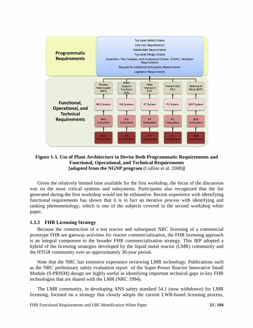
Figure 1-5. Use of Plant Architecture to Devise Both Programmatic Requirements and Functional, Operational, and Technical Requirements [adapted from the NGNP program (Collins et al. 2008)]
Given the relatively limited time available for the first workshop, the focus of the discussion
was on the most critical systems and subsystems. Participants also recognized that the list generated during the first workshop would not be exhaustive. Recent experience with identifying functional requirements has shown that it is in fact an iterative process with identifying and ranking phenomenology, which is one of the subjects covered in the second workshop white paper.
1.3.3 FHR Licensing Strategy Because the construction of a test reactor and subsequent NRC licensing of a commercial
prototype FHR are gateway activities for reactor commercialization, the FHR licensing approach is an integral component to the broader FHR commercialization strategy. This IRP adopted a hybrid of the licensing strategies developed by the liquid metal reactor (LMR) community and the HTGR community over an approximately 30-year period.
Note that the NRC has extensive experience reviewing LMR technology. Publications such as the NRC preliminary safety evaluation report of the Super-Power Reactor Innovative Small Module (S-PRISM) design are highly useful in identifying important technical gaps in key FHR technologies that are shared with the LMR (NRC 1994).
The LMR community, in developing ANS safety standard 54.1 (now withdrawn) for LMR licensing, focused on a strategy that closely adopts the current LWR-based licensing process,

FHR Functional Requirements and LBE Identification White Paper 24 | 104
except where differences are mandated by unique features of LMR design. To do this, the ANS standard provides a set of GDC for LMRs, which are derived from the LWR-based GDC in Appendix A of 10 CFR 50 (NRC 2007). These LMR GDC maintain a one-to-one correspondence to the Appendix A GDC. Historically, licensing for both HTGRs and SFRs has undergone the process of identifying which GDC were being met and which were in fact inapplicable (NRC 1994).
Upcoming work by a new committee of the American Nuclear Society (ANS) to create a safety standard for FHRs, ANS 20.1, will provide the basis to develop consensus-based FHR-specific General Design Criteria (GDC) derived from existing LWR-specific GDC, to be used in licensing reviews. ANS 20.1 could be used by the regulator to judge if the FHR design conforms to the current regulatory requirements contained in 10CFR 50 or 10CFR 52. The determination is made by reviewing the application against the NRC standard review plan (may be tailored to account for unique design features) using the General Design Criteria as acceptance criteria. If the NRC endorses ANS 20.1 then the ANS 20.1 requirements will be used in lieu of Appendix A of 10CFR 50 as acceptance criteria. This was also the approach by which the MHTR, CRBR, SAFR, and PRISM were reviewed.
Figure 1-6 illustrates how the FHR GDC would be derived from the existing LWR GDC. One of the major goals of the new ANS safety standard for FHRs is to generate a consensus set of FHR-specific GDC, using a similar process to that applied in ANS 54.1 to develop LMR-specific GDC (in fact, many of the LMR-specific GDC apply directly to FHRs, because both are high-temperature, low-pressure reactor designs).

FHR Functional Requirements and LBE Identification White Paper 25 | 104
Figure 1-6. FHR-Specific SDC Categories and FHR Detailed Safety Functions
A technology-neutral licensing or safety analysis framework is an “iterative process for the application of defense-in-depth principles that takes into consideration uncertainties” (Fleming 2006). The generation of FHR SDC is one of the products of using the technology-neutral framework. The purpose of the SDC is not to provide an alternative licensing path to 10 CFR 50 Appendix A (LWR GDC), but rather to ensure that the LWR GDC are appropriately adapted for the licensing of FHRs (NRC 2005; IAEA 2007).
The HTGR community, on the other hand, in developing ANS safety standard 53.1 (American Nuclear Society 2011) for HTGR licensing, adopted a technology-neutral framework that focuses on fundamental functions for reactor safety. For a reactor technology like the FHR with many novel elements, which do not have a significant experience base, this technology-neutral framework provides the best approach to guide reactor design and safety analysis.
Both PBMR and more recently designs from the NGNP have undergone extensive pre-application discussion and review with the NRC, where preliminary licensing and design feedback was provided to the HTGR designers [e.g., (Idaho National Laboratory 2010a; Idaho

FHR Functional Requirements and LBE Identification White Paper 26 | 104
National Laboratory 2010b; Idaho National Laboratory 2011)]. Much of this work, such as critical white papers assembled by the DOE, is publicly available and highly instructive for developing a framework to guide the design and safety analysis of FHR reactor technology.
As listed in Table 1-3, the HTGR design and licensing strategy can be best thought of as addressing a set of four critical elements in the reactor design certification process. These fundamental elements are all connected and drive the logical approach for design and safety analysis. The issues are rooted in reactor safety principles and based on the “risk triplet” concept.
Table 1-3. HTGR Licensing Strategy (F. A. Silady 2006)
Metric Purpose
Top-Level Regulatory Criteria (TLRC) Establish what must be achieved
LBE Define when the TLRC must be met
SDC Safety Classifications of SSCs
Establish how it will be assured that the TLRC are met
Deterministic Design Conditions Special Treatment Requirements
Provide assurance as to how well the TLRC are met
The TLRC are best thought of as acceptable radiological consequences from reactor operations – both normal and off-normal. Special considerations for the use of TLRC for FHRs in the pre-conceptual design phase are discussed further in Section 4.1.3.
The main focus of the first workshop was on the second and third elements listed, including the establishment of SDC and identification of LBEs. The establishment of SDC is essential, as they define key groups of functional requirements important to safety. SDC represent high-level safety requirements specific to FHRs. As shown in Figure 1-6, the SDC provide the primary framework to organize FHR design and safety assessment. The resulting FHR design and safety functions then provide a basis to review LWR GDC for applicability to FHRs and to develop FHR-specific GDC to facilitate NRC license application reviews.
Chapter 2 presents FHR SDC recommended by the first workshop and reviews FHR-specific technical strategies for meeting these SDC.

FHR Functional Requirements and LBE Identification White Paper 27 | 104
2 FHR SDC and System Decomposition
As shown earlier in Figure 1-6, SDC can be derived from high-level, technology-neutral safety functions for fission reactors, based on the extensive experience to date with other reactor types, particularly LWR technology and its associated GDC. The SDC proposed here for FHRs are adapted from the PBMR “Required Safety Functions” listed in Table 2-1 and the LMR “Top-Level Safety Functions” listed in Table 2-2. The six PBMR “Safety Functions” are organized in a hierarchical structure that includes the first four of their “Required Safety Functions” along with additional “supporting safety functions,” which are not required, but provide defense in depth (F. A Silady 2006). Similarly, the modular HTGR identified a set of “Principal Design Criteria,” and LMRs defined a set of eight “Top-Level Safety Functions.”
Table 2-1. PBMR “Safety Functions”
A. Maintain Control of Radionuclides
B. Control Heat Generation (Reactivity)
C. Control Heat Removal
D. Control Chemical Attack
E. Maintain Core and Reactor Vessel Geometry
F. Maintain Reactor Building Structural Integrity
Table 2-2. LMR “Top-Level Safety Functions”
a. Overall Protection
b. Core Heat Removal
c. Reactivity Control
d. Maintenance of Coolant Inventory
e. Residual Heat Removal
f. Containment of Radioactive Material
g. Containment Heat Removal
h. Prevention and Mitigation of Energetic Reactions

FHR Functional Requirements and LBE Identification White Paper 28 | 104
SDC can be used to develop a high-level strategy for ensuring safety of FHRs, which then guides the identification of functional requirements for SSCs and the detailed design of these SSCs. A major element of the ANS safety standard development will involve review of the LWR GDC for applicability to FHRs. However, before reviewing each of the 64 GDC and their applicability to FHRs, the initial step is to define the overall safety philosophy for FHRs. The SDC and the strategy for meeting them can guide the review of the GDC for applicability to FHRs and provide a framework for ensuring completeness of the FHR-modified GDC.
Each element of the SDC defines a class of lower-level safety functions. For example, “Tritium management” is a lower-level safety function that is subordinate to “Maintain control of radionuclides.” More than one system is involved in meeting this safety function, e.g., “coolant chemistry control” and “cover gas chemistry control.” The proposed subordinate safety functions for each of the SDCs are presented in the remainder of this chapter, and they lead to a preliminary subset of the system and subsystem functional requirements presented in Appendix A.
Table 2-3 lists proposed high-level SDC for FHRs (Blandford 2008). These FHR SDC are derived from criteria originally proposed for the PBMR (F. A Silady 2006), with the key change that the PBMR SDC to “prevent chemical attack” is replaced by “control coolant inventory” to reflect the fact that in FHRs the fuel is protected from contact with air or steam as long as it is immersed in the chemically non-reactive liquid coolant, and the SDC “control heat removal” is expanded to include “and addition” because FHRs include electrical and other heating systems to prevent overcooling.
Table 2-3. Proposed FHR SDC
(1) Maintain control of radionuclides
(2) Control heat generation (reactivity)
(3) Control heat removal and addition
(4) Control primary coolant inventory
(5) Maintain core and reactor vessel geometry
(6) Maintain reactor building structural integrity
Section 2.1 provides additional background on the decomposition of FHR systems before
describing the strategy for meeting the SDC. The following sections of this chapter review the FHR SDC and provide high-level descriptions of how FHRs can meet these requirements. For each SDC, a set of subordinate safety functions that relates directly to meeting the SDC is listed. These subordinate safety functions, in conjunction with other top-level end-user and stakeholder criteria, can be used to develop the functional requirements for key FHR systems and subsystems.
FHR Functional Requirements and LBE Identification White Paper 29 | 104
2.1 FHR System Decomposition
This system decomposition approach integrates the higher-level PASSC convention used by the NGNP (Collins et al. 2008) with the decomposition paradigm for a hierarchical two-tier scaling analysis (H2TS) methodology (Zuber et al. 1998).
The PASSC convention includes areas, systems, subsystems, and components. It is convenient to use this convention because the SSCterminology is important in safety classification established by 10 CFR 50.69 (F. A Silady 2006), and it easily maps onto the convention.
The H2TS system decomposition paradigm includes the system, subsystems, modules, constituents, geometrical configurations, physical phases (gas, liquid, and solid), fields, and phenomena. Fields were chosen to be consistent with scaling methods. Using this paradigm allows for direct application of the PIRT results to the design of scaled experiments. It also facilitates application of analytical calculations to support qualitative phenomena ranking rationale.
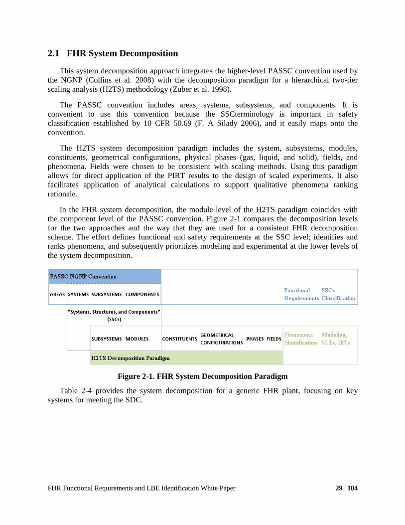
In the FHR system decomposition, the module level of the H2TS paradigm coincides with the component level of the PASSC convention. Figure 2-1 compares the decomposition levels for the two approaches and the way that they are used for a consistent FHR decomposition scheme. The effort defines functional and safety requirements at the SSC level; identifies and ranks phenomena, and subsequently prioritizes modeling and experimental at the lower levels of the system decomposition.
Figure 2-1. FHR System Decomposition Paradigm
Table 2-4 provides the system decomposition for a generic FHR plant, focusing on key systems for meeting the SDC.

FHR Functional Requirements and LBE Identification White Paper 30 | 104
Table 2-4. FHR System Decomposition for Key SSC
Areas Systems Subsystems
Nuclear Heat Supply
Reactor
Fuel Primary coolant Primary pump Graphite structures Core barrel and downcomer Upper core support structures
Reactivity Control Reactivity control system Reserve reactivity control system
DRACS
DRACS heat exchanger and diode DRACS piping and insulation/ electrical heating Natural decay heat exchanger
Reactor Vessel and Reactor Cavity
Reactor vessel/guard vessel Reactor cavity cooling and insulation Electrical heating Buffer salt (if used) Concrete walls
Heat Transport Intermediate Loop
Intermediate heat exchanger Power conversion heat exchanger Process heat exchanger Shutdown cooling and maintenance heat removal Piping and drain tank
Main Support Systems
Coolant chemistry, particulates and inventory control Cover gas chemistry, particulates and inventory control Fuel handling and storage Plant instrumentation and control, and safety systems control
Power Units Power conversion system Process heat system
Balance of Plant
Fire protection system Reactor citadel Seismic base isolation External event shield Heating, ventilation, and air conditioning Component cooling and service water Radioactive waste handling AC/DC power supply and distribution Control rooms

FHR Functional Requirements and LBE Identification White Paper 31 | 104
Appendix A presents a set of major functional requirements for FHR and the systems and subsystems level, which will guide the design and development of FHRs to ensure that regulatory and other requirements and performance goals are met. Because detailed designs for FHR systems have not yet been developed, the functional requirements also establish a set of performance assumptions.
Functional requirement identification is an iterative process with LBE identification. This workshop began with the definition of functional requirements, followed by LBE identification. Subsequent iterations of this process during FHR system design will enable classification of the functional requirements by operational state and identification of reliability requirements for each of the functions. SSC safety classification will then follow.
2.2 SDC 1 - Maintain Control of Radionuclides
The largest radionuclide source term in an FHR resides in the fuel located in the reactor core, fuel transfer system, and fuel storage system. FHRs use high-temperature, coated-particle fuel. Additionally, much smaller quantities of radionuclides outside the fuel are substantially more mobile, consisting of neutron activation products formed in the coolant and structures and small quantities of fission products released from defective fuel particles and from fission of tramp uranium in the binder material around fuel particles.
Table 2-5 lists the engineered safety functions that primarily relate to the control of radionuclides. The order of the table reflects the multiple barriers that provide defense in depth to release of radionuclides from the source term to the environment and barriers to release for worker protection. The functional requirements for the engineering safety systems that are used to meet these safety functions are discussed further in Chapter 4; they additionally relate to other SDC as well as reliability and other criteria.
Table 2-5. Engineered Safety Functions Primarily Related to SDC 1
SDC 1: Maintain Control of Radionuclides
1. Tristructural-isotropic (TRISO) particle fuel integrity
2. Primary coolant chemistry, particulates, and inventory control
3. Tritium control and recovery
4. Cover gas chemistry, particulates, and inventory control
5. Reactor cavity low-pressure containment
6. Fuel transfer and storage
7. Reactor citadel filtered confinement

FHR Functional Requirements and LBE Identification White Paper 32 | 104
2.2.1 Fuel Source Term Compared to other reactor technologies, FHRs maintain very large thermal margins to fuel
damage under design basis accidents and transients, while using passive decay heat removal. The thermal limit for the coated-particle fuel used in FHRs is over 1600°C. As long as the fuel remains immersed in coolant (SDC 4), it is nearly impossible to raise the fuel temperature above the coolant boiling temperature (1430°C). Actual peak temperatures for design basis transients and accidents are hundreds of degrees lower and are limited by peak temperatures reached by metallic primary loop structures and components (SDC 3 and 5). The fact that FHRs will have a very large (hundreds of degrees) thermal margin to fuel damage has important implications for FHR design and safety analysis, because the power level for a given reactor core design (one of the most important parameters affecting economics) will be established by criteria other than thermal limits on fuel damage. The potential limiting criteria for FHR thermal power include peak metallic component temperature during design basis accidents, reflector lifetime from neutron dose limits, and peak fuel particle power.
For comparison, in reactor technologies that use metallic fuel cladding (e.g., LWRs and SFRs), the limits on reactor power are generally established by limits on local peak cladding temperature during design basis transients and accidents. Likewise, for gas-cooled reactors that use ceramic fuel (e.g., MHRs), the reactor power is limited by local peak fuel temperature and fuel damage during depressurized conduction cool-down events.
Methods for spent fuel handling and transfer in FHRs will depend on whether fixed- or pebble fuel designs are used. Pebble fuels will use similar systems to the PBMR, except they will be physically smaller because the FHR pebbles are approximately half the diameter of the PBMR pebbles. The defueling chute of a pebble FHR will be designed to provide a sufficiently long residence time (1 to 2 days) that short-lived fission products will decay before pebbles are removed and enter the fuel transfer and storage system. Pebble-fueled FHRs will also have the capability to rapidly transfer fuel pebbles to defuel the core; however, in this case the fuel transfer will only be initiated after the reactor has been shut down for an appropriate period of time (1 to 2 days).
In addition to having very large thermal margins for fuel damage, FHRs will also feature multiple additional barriers that will provide defense in depth and limit any release of radionuclides in the event that fuel is damaged. The primary role of these additional barriers is to control releases of circulating activity and beryllium, as discussed in the next subsection.
2.2.2 Tritium and Other Circulating Activity Circulating activity in the FHR primary system will include neutron activation products and
fission products generated from defective fuel particles and tramp uranium. Non-noble-gas fission products will have high solubility in the primary coolant, if they form stable fluorides. Noble metals have low solubility and will deposit primarily in the intermediate heat exchanger. Noble gas fission products are expected to be released in such small quantities that no control is required.
Because the primary coolant is solid at room temperature, a number of mechanisms could generate coolant particulate aerosols, including condensation of coolant vapor (primarily the higher volatility BeF2 component) as well as mechanical generation from both the liquid and

FHR Functional Requirements and LBE Identification White Paper 33 | 104
solid salt (primarily during maintenance activity and from erosion of pebble surfaces during movement in the fuel handling and storage system). Control of these particulates is important for worker safety because the particles will contain beryllium, so the FHR industrial safety program for beryllium will be closely integrated with its radiation control program and will share many elements (such as common air monitoring equipment).
Aerosols in FHRs will be controlled by a variety of systems, including the cover gas and reactor cavity gas chemistry, and particulate and inventory control systems; the low-pressure, low-leakage containment function provided by the reactor cavity; the filtered confinement function of the citadel structure that encloses the reactor cavity and provides personnel access; and additional hold up provided by the external event shell that surrounds the citadel structure.
Figure 2-2 illustrates a potential configuration of a reactor building and its associated heating, ventilation, and air conditioning (HVAC) zones. Note that the HVAC system collects exhaust flows from both the filtered confinement volume and the external event shell volume. These flows are directed to the plant exhaust stack, allowing any radioactivity releases to be monitored.
Figure 2-2. HVAC Zones in an FHR Reactor Building: Reactor Cavity (yellow), Filtered
Confinement (green), and External Event Shell (blue/purple) (Fei et al. 2008)
The most mobile activation product formed in FHRs is tritium. The production of tritium in an FHR is over an order of magnitude greater than tritium production in PWRs, but also over an order of magnitude smaller than the production of tritium in Canada Deuterium Uranium (CANDU) reactors. Unlike in water-cooled reactors, tritium has very low solubility in the primary coolant of an FHR. Tritium also diffuses readily through those portions of the primary and intermediate loop pressure boundaries that operate at high temperature, particularly the intermediate heat exchanger and the heaters that transfer heat to the power conversion fluid. The strategy for tritium control will depend on the power conversion technology used with an FHR, with steam-Rankine and open-air-Brayton cycles having more challenging tritium control needs
Turbine Hall
IHX Valve Room
Cover Gas Control System
Pebble Transfer Cell
Reactor Vessel Cavity

FHR Functional Requirements and LBE Identification White Paper 34 | 104
than closed gas-Brayton cycles. In all cases, some type of tritium recovery will likely be needed to control worker exposure and environmental releases.
2.3 SDC 2 – Control Heat Generation (Reactivity)
Table 2-6 lists the FHR engineered safety functions that primarily relate to reactivity control. Normal reactivity control, shutdown systems, and reserve shutdown systems are designed for high reliability, and the coolant and core design are selected to provide negative void reactivity feedback.
Important differences will exist between FHRs using fixed versus pebble fuels, because the fixed-fuel designs will operate with greater excess reactivity while pebble-fueled cores will operate with low excess reactivity. The variety of reactivity control and shutdown options for FHRs include (1) the use of control rods and shutdown rods, which may be buoyantly inserted; (2) absorbing spheres; (3) soluble poisons; and (4) addition or removal of fuel (for pebble-bed FHRs) (Blandford and Peterson 2008). For fixed-fuel designs (and less so for pebble fuel designs), inadvertent control element removal must be considered as a potential reactivity-induced transient.
Table 2-6. Engineered Safety Functions Primarily Related to SDC 2
SDC 2: Control Heat Generation (Reactivity Control)
1. Normal reactivity control
2. Normal shutdown function
3. Reserve shutdown
4. Intrinsic core temperature feedback
The main motivation for selecting flibe (a mixture of BeF2 and enriched 7LiF) as the primary coolant for FHRs is the ability to design FHR cores that have negative coolant temperature and void reactivity feedback. This safety feature has been judged to outweigh the negative impacts that come from requiring a beryllium safety program, and in most cases the improved fuel utilization arising from the low parasitic neutron capture in flibe can justify the higher cost of the salt. To obtain negative coolant temperature and void reactivity feedback, the core must be under-moderated, and in general the additional moderation provided by the coolant causes FHR core designs to optimize at significantly higher heavy metal loading than MHRs. A key safety issue for FHRs, though, is the requirement to remain under-moderated during initial fueling, which affects the approach taken to add fuel to the core.
Experiments performed at UCB found that control rods could be inserted directly into the pebble bed with small forces and minimal bed disturbance (Blandford and Peterson 2008). The forces on control elements inserted directly into FHR pebble beds are expected to be much less than those for helium-cooled reactors because of the small effective gravity force of the buoyant
FHR Functional Requirements and LBE Identification White Paper 35 | 104
pebbles and the additional degrees of freedom for the free surface at the bottom of the bed. However, it is anticipated that channels would be provided for insertion of rods and absorbing spheres, so that insertion forces can remain low. In FHRs, though, drag forces on the shutdown elements can be important, particularly for buoyant shutdown where the driving force is small, and for absorbing spheres where the drag force may be large.
2.3.1 Important Reactivity Transients While unprotected shutdown transients (anticipated transient without scram, ATWS) have a
frequency that falls within the beyond design basis event (BDBE), the response of FHRs to ATWS is still modeled to verify the absence of cliffs with consequences such as significant damage to metallic structures. FHR ATWS response has important differences from ATWS response in LWRs and MHRs. In FHRs the coolant temperature reactivity feedback coefficient is around one third to one fifth of the fuel reactivity feedback. Because under power operation the fuel is at a higher average temperature than the coolant, to shut down the reactor purely on negative temperature feedback the local fuel and coolant temperatures must equilibrate to be approximately equal, and the local coolant temperatures will equilibrate close to the original fuel temperatures so that the negative reactivity insertion from heating the coolant cancels the positive insertion from cooling the fuel. While the shutdown and reserve shutdown systems should be designed to have sufficient reliability to make ATWS a BDBE, it will be important to be able to simulate the coupled neutronic and thermal hydraulic phenomena that occur during ATWS in FHRs.
Another important transient to model is the FHR startup transient. At zero power, the FHR core is nearly isothermal, so to increase power reactivity must be inserted to overcome the negative reactivity feedback as the coolant and fuel temperatures rise. The reactivity insertion required to reach various levels of power is an important parameter that can be measured during low-power startup testing, and can validate modeling predictions for core temperature distributions and resulting reactivity feedback that are also important for ATWS transients. One important focus for core design is to improve heat transfer and maintain average fuel temperatures as low as possible, to minimize the reactivity insertion needed to reach full power. While power ascension is likely to occur over a relatively short time period compared to the time constants for xenon decay, design of reactivity control must also consider the additional reactivity insertion required to maintain power as equilibrium xenon buildup is reached.
It would be preferable if existing neutronic experimental data, such as from the MSRE, could be used to validate neutronic models for the FHTR. However, it will be important to define a start-up test protocol for the FHTR and subsequent commercial reactors that would provide validation of safety models. Shutdown rod and control rod worth can be measured with subcritical, source-driven neutron multiplication measurements. Zero-power and lower-power critical tests can measure power-reactivity feedback to validate models for fuel and coolant reactivity feedback.
2.4 SDC 3 – Control Heat Removal and Addition
The control of heat removal is important to prevent overheating of reactor structures and to limit thermal stresses and thermal creep deformation during transients and accidents. The control of heat addition and excessive heat removal is important to prevent and recover from overcooling

FHR Functional Requirements and LBE Identification White Paper 36 | 104
transients that might cause localized freezing of the primary or secondary coolants and subsequently inhibit control of heat removal. Table 2-7 lists the FHR engineered safety functions that relate primarily to heat removal or addition.
Table 2-7. Engineered Safety Functions Primarily Related to SDC 3
SDC 3: Control Heat Removal and Addition
1. Normal heat load (power units)
2. Shutdown, startup, and maintenance cooling
3. Passive decay heat removal
4. Reserve shutdown cooling for decay heat removal (if used)
5. Reactor cavity cooling
6. Heat sink throttling for parasitic heat load control
7. Reactor cavity thermal insulation and electrical heating
8. Electrical heating systems for salt inventories external to reactor cavity
2.4.1 Overheating Transients FHRs will have four primary heat removal pathways. For one, under power operation, the
power conversion system (or process heat exchangers) will provide a large heat sink coupled through the intermediate loop or loops and intermediate heat exchangers to the primary loop.
The intermediate loop will also have a normal shutdown cooling system, providing the second heat removal pathway, with a water- or air-cooled heat exchanger that operates actively (possibly using auxiliary circulation pumps on the intermediate loop) to provide normal shutdown heat removal. An FHR will normally have two to four intermediate heat exchangers. If normal shutdown cooling is provided using the intermediate loop, then the intermediate loop associated with each heat exchanger should be designed so that individual loops can be isolated to allow maintenance while an alternative intermediate loop is used for shutdown cooling. Under this approach, the reliability of normal shutdown cooling may be increased because of the redundancy of shutdown cooling systems. Alternatively, a separate normal shutdown cooling system may be provided with a separate heat exchanger in the primary system.
As an active system, the normal shutdown cooling system is expected to be able to control heat removal to minimize thermal transients to the intermediate heat exchanger and reactor vessel. The normal shutdown cooling system can likely be designed to be capable of removing decay heat using natural circulation heat transfer. While passive operation would reduce the ability to minimize the thermal transient of the heat exchangers and reactor vessel, this reserve shutdown-cooling mode would have high reliability. Furthermore, if the shutdown cooling heat

FHR Functional Requirements and LBE Identification White Paper 37 | 104
exchanger is designed to be water cooled, evaporation could be used for reserve shutdown heat removal, providing diversity in the ultimate heat sink because the heat sink for emergency decay heat removal is likely to be ambient air.
Emergency decay heat removal in FHR would use a DRACS that operates using natural circulation without electrical power, providing the third heat removal pathway. The DRACS ultimate heat sink is likely to be air drawn at a high elevation into hardened chimneys and flowing downward in an annular space around an insulated hot air vent pipe that returns heated air to exhaust louvers at the tops of the chimneys. Normally the air flow entering the natural draft heat exchangers at the bottom of the chimneys will be throttled by a damper to the minimum air flow required to remove heat from the outside of the insulated vent pipe and keep the chimney structure within thermal limits. The DRACS must have the capability to be throttled to be able to control overcooling, and inlet air would normally be throttled to reduce parasitic heat loss. Depending on the capacity of the normal shutdown cooling system, the dampers may be opened briefly following a reactor trip to increase heat removal and reduce the thermal transient delivered to the heat exchanger and reactor vessel.
The fourth heat removal path is the reactor cavity cooling system. Either the reactor cavity or the reactor vessel will be insulated. Because heat will leak through this insulation, the cavity liner must be cooled to remove this heat and maintain the concrete at an acceptable temperature. It is desirable that the reactor cavity provides an alternative heat removal pathway during BDBEs. As discussed under SDC 4, control coolant inventory, it may be appropriate to have the capability to flood the reactor cavity with a low-cost “buffer” salt such as sodium fluoroborate using various potential methods. The thermal resistance of many porous insulation systems will drop greatly when filled with a liquid rather than gas, potentially providing an appropriate approach to couple the reactor vessel thermally to the reactor cavity, so that the reactor building structure and reactor cavity cooling system can provide a heat sink.
Because the most important thermal limits in FHRs involve metallic structures located outside the reactor core, predicting the integral thermal response of the reactor core (power and flow) is of greater interest rather than local, maximum temperatures of fuel in the core for accidents and transients. The fact that integral, averaged parameters, rather than local maximum parameters, are more important in predicting FHR safety has implications for the nature of uncertainty quantification in FHR transient modeling. In general, integral parameters are easier to predict using relatively simple models that emerge from volume and time averaging of the conservation equations for mass, energy, and momentum. While care must be taken in measuring integral parameters in experiments, it is commonly easier to measure integral parameters than to measure local maximum parameters. This difference between FHRs and other reactor technologies has also has implications for the design of integral effect tests to validate transient response models. In addition, it has implications for the design of reactor startup testing protocols. These implications suggest that it will be important, early on, to identify what startup testing protocol would be most effective in validating transient response models under fully prototypical conditions, and then provide the instrumentation needed to make these measurements in the design of the reactor. It is also important to provide, to the extent possible, the same instrumentation in the integral effects tests performed to support the licensing of the reactor.
FHR Functional Requirements and LBE Identification White Paper 38 | 104
2.4.2 Overcooling Transients Fluoride salts have high freezing temperatures. Localized freezing could block coolant flow
and disable heat removal by forced and natural circulation. Thus, FHR systems must be designed to prevent and recover from overcooling resulting in localized freezing of salts.
The design of heat exchangers to prevent and recover from freezing is an important area of design for FHRs. The MSBR intermediate heat exchanger design used knurled tubes to enhance heat transfer, and such tubes are also likely to be more resilient if subjected to freeze-thaw cycles.
More generally, prevention of overcooling requires the capability to control heat removal. While the heat removal capability of the power conversion system will be very large, the combined heat removal capability of the normal shutdown cooling system, DRACS, and reactor cavity cooling system will greatly exceed normal decay heat generation. After prolonged shutdown, and if the reactor is defueled, the parasitic heat loads from the reactor cavity cooling system and the minimum heat removal rates needed to maintain minimum temperatures for the DRACS and intermediate loops can be expected to exceed the rate of decay heat generation. At this point, electrical resistance heating will be required to prevent overcooling. This electrical heating system will need to be designed to have sufficient reliability, meaning that it will require redundancy for heaters in the reactor cavity and for trace heating of DRACS and intermediate loop piping outside the reactor cavity, as well as diversity of power supply (offsite power, installed onsite power, and portable power systems). Additionally, the intermediate loop(s) may be designed to be drained to a tank or tanks.
2.5 SDC 4 – Control Primary Coolant Inventory
Controlling primary coolant inventory prevents fuel overheating, eliminates the possibility of highly exothermic chemical reactions in the core, and ensures heat transfer transport pathways from the core. For FHRs, it is a more fundamental SDC than controlling chemical attack, which is used as an SDC for gas-cooled reactors. Table 2-8 lists the FHR engineered safety functions that primarily relate to coolant inventory control. The prioritization of the safety functions in the table reflects the defense-in-depth strategy for meeting SDC 4. The first layer of defense is the normal primary coolant inventory control and integrity of primary pressure boundary, followed by a diverse set of options for adding salt inventory if the first layer of defense fails.
As long as FHR fuel remains submerged in salt coolant, it is physically nearly impossible to raise the fuel to temperatures at which damage could occur or for chemical attack by air or water. (Note that chemical attack could, in principal, occur to graphite or carbon-carbon composite structures that extend above the surface of the salt pool, and this must be considered in detailed design).

FHR Functional Requirements and LBE Identification White Paper 39 | 104
Table 2-8. Engineered Safety Functions Primarily Related to SDC 4
SDC 4: Control Coolant Inventory
1. Normal primary coolant inventory control
2. Integrity of primary pressure boundary
3. Buffer salt inventory control
4. Intermediate loop coolant (if used) inventory control
5. DRACS coolant inventory control
6. Portable external salt injection capability
Because the primary coolant for FHRs is expensive, to minimize the reactor capital cost it is
desirable to minimize the volume of salt used in the system, in general by displacing it with graphite wherever possible. However, the large primary salt inventory must be sufficiently large so that the fuel remains covered and natural circulation heat removal remains functional under design basis transients and accidents.
Designers should also evaluate potential mechanisms where cover gas or other gas might be ingested and pumped into the primary loop, displacing primary coolant. Following primary pump shutdown, these gases might vent, lowering the collapsed primary coolant level.
FHRs use a pool configuration or a hybrid pool/loop configuration that greatly reduces the probability of loss of coolant accidents. Designers must still consider a spectrum of potential primary pressure boundary leaks, for example evaluating the effects of a heat exchanger tube break where primary pumps might pump primary coolant into the intermediate loop. As with pool-type LMRs, FHR design must also consider the potential for a reactor vessel leak or rupture.
In general, it is likely to be advantageous to have the capability to add salt into the reactor primary system and possibly into the guard vessel and reactor cavity as well. Good design would use the normal primary salt volume control system for this purpose and would provide a back-up source of low-cost salt that could be injected using this system if needed. Likewise, the volume control system for the intermediate salt loop could be designed to cross tie and provide injection into the primary system, guard vessel, or reactor cavity. Additionally, a variety of options are possible for additional inventories of salt. For FHRs, what is commonly referred to as “buffer” salt is available inside the reactor cavity in solid or melted forms, to fill the gap between the reactor vessel and a guard vessel, or to be available in other locations to fill the reactor cavity or primary system during BDBEs. Finally, the capacity to inject salt into the primary loop, guard vessel, or reactor cavity using external, portable equipment could potentially be employed.
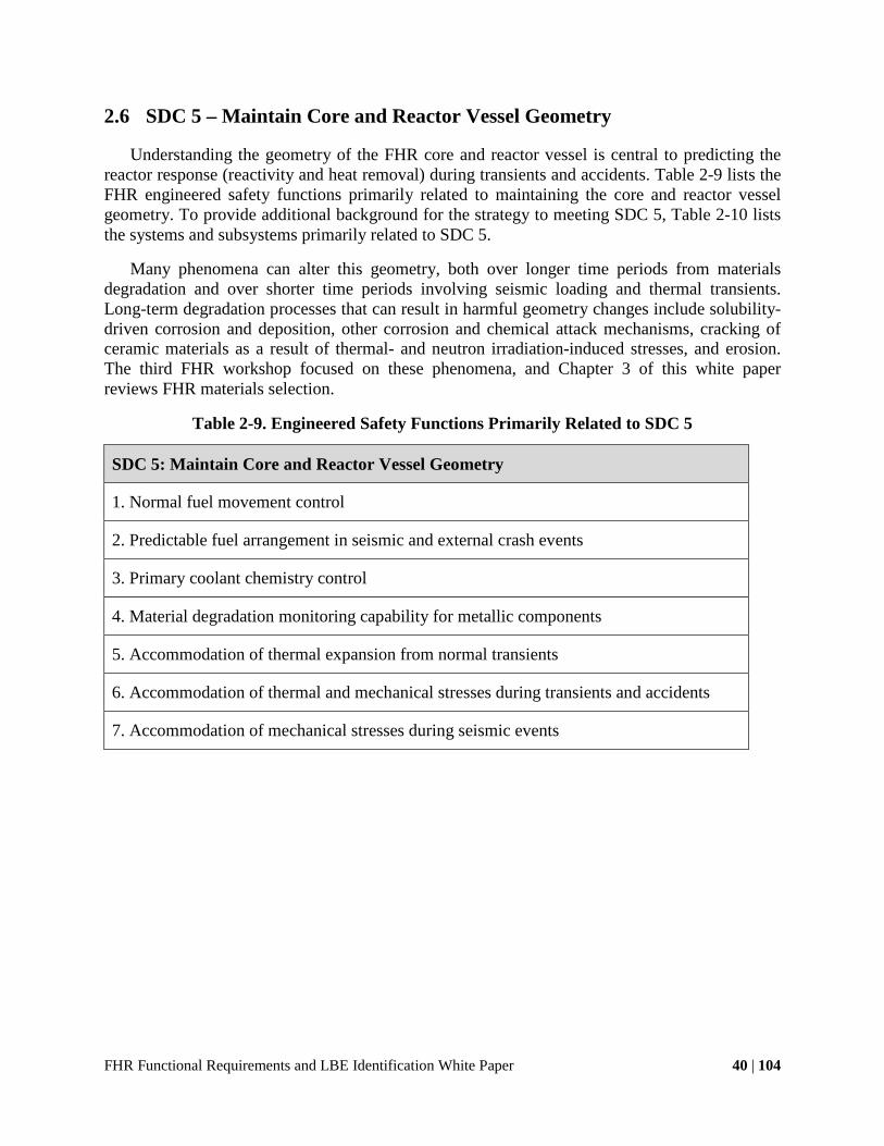
FHR Functional Requirements and LBE Identification White Paper 40 | 104
2.6 SDC 5 – Maintain Core and Reactor Vessel Geometry
Understanding the geometry of the FHR core and reactor vessel is central to predicting the reactor response (reactivity and heat removal) during transients and accidents. Table 2-9 lists the FHR engineered safety functions primarily related to maintaining the core and reactor vessel geometry. To provide additional background for the strategy to meeting SDC 5, Table 2-10 lists the systems and subsystems primarily related to SDC 5.
Many phenomena can alter this geometry, both over longer time periods from materials degradation and over shorter time periods involving seismic loading and thermal transients. Long-term degradation processes that can result in harmful geometry changes include solubility-driven corrosion and deposition, other corrosion and chemical attack mechanisms, cracking of ceramic materials as a result of thermal- and neutron irradiation-induced stresses, and erosion. The third FHR workshop focused on these phenomena, and Chapter 3 of this white paper reviews FHR materials selection.
Table 2-9. Engineered Safety Functions Primarily Related to SDC 5
SDC 5: Maintain Core and Reactor Vessel Geometry
1. Normal fuel movement control
2. Predictable fuel arrangement in seismic and external crash events
3. Primary coolant chemistry control
4. Material degradation monitoring capability for metallic components
5. Accommodation of thermal expansion from normal transients
6. Accommodation of thermal and mechanical stresses during transients and accidents
7. Accommodation of mechanical stresses during seismic events

FHR Functional Requirements and LBE Identification White Paper 41 | 104
Table 2-10. FHR Systems and Subsystems Primarily Related to SDC 5
SDC 5: Maintain Core and Reactor Vessel Geometry
Fueling and defueling systems
Shutdown rod channel system (example: liners)
Internal core structures (examples: grid spacers, composite liners)
Graphite radial and axial reflectors
Core barrel
Reactor vessel
Upper core structures (includes hold-down structure and thermal shield)
Guard vessel (if used)
Insulated reactor cavity structure
Primary coolant chemistry, particulates and inventory control system
In-service inspection, online monitoring, and post-accident monitoring systems
Seismic events may result in damage to reactor structures or in reactivity control element or
fuel element movement (particularly for pebble fuel). Shake table experiments performed at UCB suggest that seismically-induced movement in FHR pebble beds is minimal, primarily because the pebbles are nearly neutrally buoyant and seismic forces on pebbles are reduced correspondingly.
Reactor startup, accidents, and transients can cause geometry changes as a result of thermal expansion. Differential thermal expansion will require careful attention during design, particularly for materials with large differences in thermal expansion coefficients (e.g., metals versus ceramics).
From the perspective of large changes in geometry, however, the most important concern involves the potential for rapid creep deformation of metallic structures subjected to significant overheating. The temperatures that cause rapid creep deformation in metallic structures are well below the boiling temperature of the salts and the thermal limits for the fuel and ceramic structures. Therefore, the ability to predict the transient temperature of metallic structures during transients and accidents, and to design these structures to mitigate and reduce these thermal effects, is a key issue for FHR safety design.

FHR Functional Requirements and LBE Identification White Paper 42 | 104
2.7 SDC 6 – Maintain Reactor Building Structural Integrity
Maintaining the reactor building structural integrity is important to being able to predict the system response during transients and accidents. Important heat transport pathways, such as the DRACS passive system for decay heat removal and the intermediate heat transport loop, are housed in the reactor building. Personnel access and additional supporting systems are also impacted by the building structural integrity and are important for accident response. An FHR reactor building can be structurally damaged because of internal and external events. Table 2-11 lists the FHR engineered safety functions primarily related to maintaining the reactor building structural integrity.
Internal events that could challenge the structural integrity of a reactor building include fires, which can overheat and weaken steel structural and reinforcing elements, and internal pressure sources. FHR reactor buildings are expected to use modular construction methods with steel/concrete composite construction. This technology, also used in the Westinghouse AP-1000 reactor, uses steel plates as the primary structural elements, cross-tied together and filled with concrete. Design of the fire protection system must consider the thermal response of these structures to fire. The primary systems in FHRs have no stored energy sources that can generate pressure. However, power conversion systems will have such stored energy sources, so reactor safety systems must be designed to control and relieve pressure appropriately if the power conversion pressure boundary fails.
Table 2-11. Engineered Safety Functions Primarily Related to SDC 6
SDC 6: Maintain Reactor Building Structural Integrity
1. Seismic base isolation of reactor citadel
2. Reactor citadel structures capability to exclude external missiles and maintain geometry under severe events
3. Reactor cavity structures capability to maintain geometry under severe events
4. External event shield structures
External events including earthquakes, severe weather (tornados and hurricanes), and missile
impact (including commercial aircraft impact) can also damage the reactor building structural integrity. UCB has studied the implementation of seismic base isolation in modular reactor buildings, as well as issues for the design of external event shells (Blandford et al. 2009).

FHR Functional Requirements and LBE Identification White Paper 43 | 104
3 FHR Materials Selection
The reliability of FHR SSCs, as well as their response during transients and accidents, will depend greatly on the specific materials selected. For the purposes of phenomena identification and ranking, the different materials used in an FHR were categorized as “constituents” and include both solids and fluids. This chapter provides a high-level discussion of these constituents, options for the specific materials to be selected, and issues in choosing between different materials options.
By identifying FHR materials options, this chapter provided input for the third workshop (FHR materials degradation and component reliability phenomena identification and ranking). This third workshop provided detailed review of dominant FHR materials degradation mechanisms (such as corrosion, erosion, wear, fouling and plugging, cyclic stress, and neutron irradiation) and associated proactive management methods that need to be understood to predict the reliability of FHR systems, subsystems, and components. In addition to identifying material degradation mechanisms, the third workshop identified functional requirements for on-line monitoring, in-service inspection, chemistry control and operational envelopes, maintenance, and replacement for subsystems and components, and reviewed the implications for the design requirements for an FHR Component Test Facility (CTF).
The next three sections review FHR fuel, fluids, and structural materials.
3.1 FHR Fuel
FHRs use TRISO-coated particle fuels originally developed for HTGRs. Table 3-1 summarizes the geometry and TRISO kernel options available for FHR fuel. Under DOE’s NGNP program, the U.S. has reestablished the capability to fabricate, irradiate, and perform post-irradiation examination on coated-particle fuels. The new coating and compacting methods developed at ORNL have been proven to produce fuel with exceptionally high quality and performance. A NGNP fuel qualification white paper (Idaho National Laboratory 2010c) provides a detailed review of the current regulatory basis for licensing coated-particle fuels including NRC regulations, policy statements, guidance documents, and licensing precedents from earlier U.S. HTGRs; summarizes existing understanding, data, and analysis methods regarding coated-particle fuel performance; reviews fuel designs and resulting fuel service conditions and performance requirements; and recommends an approach for qualification of

FHR Functional Requirements and LBE Identification White Paper 44 | 104
Table 3-1. FHR Constituents – Fuel (NGNP Derived)
Options Candidates for IRP
Geometry Pebble
Plate
TRISO kernel
Low-enriched uranium
Transuranics
Thorium
NGNP fuel. These existing NGNP capabilities are important to the development of similar coated-particle fuels for FHRs.
FHRs operate at power densities two to six times higher than those of HTGRs. Because the FHR coolant is an effective moderator, FHR fuels optimize to significantly higher heavy metal loading than HTGR fuel. In general, FHR fuels will operate with substantially higher particle powers and particle packing densities than HTGR fuels. Thus, while FHRs can use the same coated-particle technology as HTGRs, research and development is needed to demonstrate methods to fabricate FHR-unique fuel geometries, including pebble fuel and fixed-fuel designs. A major benefit of the high particle powers used in FHRs is that the fuel reaches full discharge burn up rapidly, typically in around 1 year for FHR pebble fuels. Thus, the time to develop, test, and qualify new fuels for FHRs is much shorter than for typical reactors. Because new fuel development normally takes over a decade, the fact that FHR fuel development can be completed in 3 to 4 years is a significant advantage for FHRs. The 2010 UCB senior design project class studied pebble fuel testing for FHRs and recommended test capsule designs that could be used in both the Advanced Test Reactor at Idaho National Laboratory and High Flux Isotope Reactor at ORNL (Gomez et al. 2010).

FHR Functional Requirements and LBE Identification White Paper 45 | 104
Figure 3-1. FHR Pebble Fuel, Which Uses an Inert, Low-Density Center Graphite Kernel
to Control Buoyancy and Reduce the Peak Fuel Temperature
3.2 FHR Fluids
FHRs use low-volatility salts to transport heat in their primary, intermediate, and DRACS loops, and as buffer salt. Other key fluid selections for FHRs are the power conversion fluid, the gases used as the cover for the salt and for pneumatic transfer of pebbles in the fuel transfer and storage system, and gases used in the reactor cavity, citadel, and external event shield volumes. Table 3-3 summarize the fluid options for FHRs. These fluids are discussed further below.

FHR Functional Requirements and LBE Identification White Paper 46 | 104
Table 3-2. FHR Constituents - Coolants
Constituents Candidates for IRP
Primary coolant Flibe
Buffer salt NaBF4, others
Secondary coolants Salts: KF-ZrF4, flinak, NaBF4, MgCl2-based
Liquid metals: NaK
DRACS coolant Salts: flibe, flinabe, flinak , MgCl2-based, KZrF
Liquid metals: NaK
DRACS heat sink Air, water
Shutdown cooling heat sink Water, air
Reactor cavity cooling Water, air
Table 3-3. FHR Constituents - Gases
Constituents Candidates for IRP
Cover gas Ar
Fuel transfer and storage Ar
Reactor cavity gas Ar, dry air
Filtered confinement Filtered ambient air
Power conversion Ambient air, He, CO2, steam
3.2.1 Primary Coolant Williams et al. reviewed the multiple criteria for selecting the primary coolant salt for FHRs
(Williams, Toth, and Clarno 2006). These criteria include parasitic neutron capture and moderation, creation of short- and long-lived activation products, cost, vapor pressure, chemistry control methods and corrosivity, toxicity, and thermophysical properties that affect forced convection and natural circulation heat transfer.
Five of the fluoride salts have neutron capture cross sections sufficiently low to be practical coolants for cooling FHRs: 7LiF, NaF, RbF, BeF2, and ZrF4. To obtain a reasonably low melting temperature, at least two of these salts must be mixed together. This IRP selected flibe, a eutectic mixture of 7LiF and BeF2, as its baseline coolant because it has the lowest parasitic neutron

FHR Functional Requirements and LBE Identification White Paper 47 | 104
capture of any of the possible salt combinations. Coupled with its significant capability to moderate neutrons, flibe’s neutron capture capability allows the design of FHR cores with negative coolant void and temperature reactivity feedback, which increases safety and simplifies licensing.
A key issue for the use of flibe is the requirement to use lithium that has been enriched from the natural concentration of 92.4% to approximately 99.995% 7Li. The U.S. ceased production of enriched lithium in the 1960s after producing a large inventory of 6Li and a smaller inventory of 7Li. Currently, the U.S. has an inventory of 2350 kg of enriched flibe, previously used as the intermediate coolant for the MSRE, which is available for neutronic experiments and for use as a coolant for an FHTR. The method used to enrich lithium in the U.S., which is still practiced in Russia and China, uses large quantities of mercury and is no longer permitted in the U.S. Several potential alternative enrichment methods include ion exchange chromatography (displacement and simulated moving band, macroreticular resins), polyethers (crown and lariat ethers, cryptands), complexation, electromigration, and electromagnetic isotope separations methods. Cost estimates for these methods are not yet available. PWRs use enriched 7LiOH to control pH when boric acid is added to control reactivity, typically around 3 kg at the start of a cycle and 3 to 4 kg more during the cycle. Currently U.S. PWRs obtain this enriched lithium from China (about 400 kg of 7Li per year), but security of supply provides a compelling reason to develop new, domestic capability to enrich lithium in the U.S. This effort is also clearly important for FHR development.
Because flibe has been studied extensively for use in MSRs and fusion power systems, it has a well-developed technology base for thermophysical property data as well as for chemistry and corrosion control. These topics are discussed in greater depth in white papers from the second and third workshops.
3.2.2 Intermediate Coolant Options Because nuclear properties are not important for the intermediate coolant, a wider variety of
coolant options includes fluoride salts, chloride salts, and liquid metals. Williams has reviewed multiple criteria for the selection of intermediate coolants (Williams, Toth, and Clarno 2006). For example, using an intermediate coolant that does not contain LiF would help prevent the mixing of enriched and unenriched lithium if a heat exchanger tube leaks. Alternatively, the primary coolant might be used to directly heat the power conversion fluid, where the power conversion fluid (e.g., air, helium, CO2) could be readily removed from the primary coolant if a tube leaks.
3.2.3 DRACS Coolant As with the intermediate coolant, several options could be used to create the DRACS coolant.
One option is flinabe, a mixture of LiF, NaF, and BeF2 that has a significantly lower melting temperature (320°C) than flibe. Alternatively, the DRACS coolant might be selected to be the same as the primary coolant or the intermediate coolant. Because the volume of DRACS coolant is relatively low, ensuring low corrosivity (to provide high reliability) and having a melting temperature that supports the overall design strategy to manage overcooling transients are likely to be highly weighted criteria.
FHR Functional Requirements and LBE Identification White Paper 48 | 104
3.2.4 Buffer Salt Because a potential design goal for FHRs is to minimize the total inventory of primary salt,
as a result of its cost, the capability to add salt under BDBE conditions may be valuable. As discussed in Section 2.4, one of several approaches might be used. A variety of potential low-cost salts might be used, with sodium fluoroborate being a representative candidate because of its capability to act as a strong neutron poison.
3.2.5 Heat Sinks FHRs are expected to use a combination of direct and evaporative cooling for their ultimate
heat sinks.
For power conversion, dry cooling or hybrid dry/wet cooling would be preferred to minimize water consumption, but the specific choices will depend on the power conversion method chosen and on economic and siting criteria.
For emergency decay heat removal, the baseline FHR design uses ambient air to cool the Natural Draft Heat Exchangers in the DRACS. The advantage of using ambient air as the ultimate heat sink is that the sink is essentially infinite and the mass of the equipment can be small. The disadvantage is that, with the large volumetric flow rates and low driving heads available to naturally circulate air, obstruction of the air flow path (for example from an external event damaging air intake louvers) can disable heat removal.
To provide diversity in the heat sinks for decay heat removal, the baseline FHR normal shutdown cooling system uses water from the plant circulating water system with an evaporative cooling tower or with a chiller system and a dry cooling tower (this circulating water system also provides a heat sink for the reactor building HVAC system and plant equipment). The advantage of using circulating water as a heat sink is that if the circulating water system is disabled, heat can still be removed by boiling water in the normal shutdown cooling system heat exchanger. Long-term heat removal can be provided by pumping additional water into the system periodically using installed or portable equipment.
Either water or ambient air may be used to cool the reactor cavity walls and the spent fuel storage canisters. Air provides the advantage of dry operation but will require forced circulation. Water can operate normally under forced circulation to transfer heat to the circulating water system but can also remove heat passively by boiling.
3.2.6 Gases The gases used in FHRs play important roles. The cover gas that blankets the free surfaces of
the primary, intermediate, and DRACS coolants plays a key role in chemistry control for the salts and must be dry and oxygen free. The baseline cover gas for FHRs is argon. The fuel transfer and storage system will likely use the same gas, because the gas streams mix routinely. The primary cover gas provides an important sink for tritium, and cover gas may be used deliberately to strip tritium from the primary coolant. So tritium recovery, oxygen removal, and particulate filtering are important functions for the primary cover gas chemistry control system.
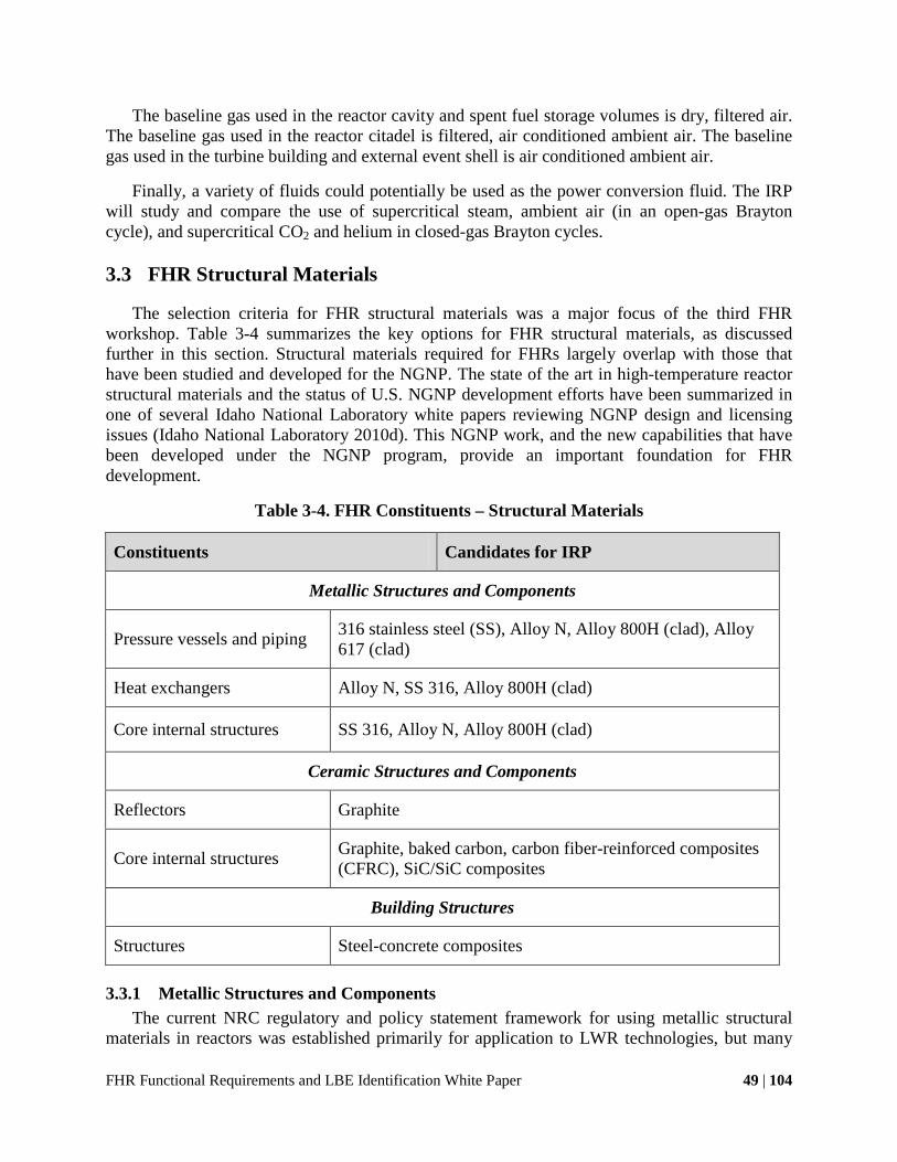
FHR Functional Requirements and LBE Identification White Paper 49 | 104
The baseline gas used in the reactor cavity and spent fuel storage volumes is dry, filtered air. The baseline gas used in the reactor citadel is filtered, air conditioned ambient air. The baseline gas used in the turbine building and external event shell is air conditioned ambient air.
Finally, a variety of fluids could potentially be used as the power conversion fluid. The IRP will study and compare the use of supercritical steam, ambient air (in an open-gas Brayton cycle), and supercritical CO2 and helium in closed-gas Brayton cycles.
3.3 FHR Structural Materials
The selection criteria for FHR structural materials was a major focus of the third FHR workshop. Table 3-4 summarizes the key options for FHR structural materials, as discussed further in this section. Structural materials required for FHRs largely overlap with those that have been studied and developed for the NGNP. The state of the art in high-temperature reactor structural materials and the status of U.S. NGNP development efforts have been summarized in one of several Idaho National Laboratory white papers reviewing NGNP design and licensing issues (Idaho National Laboratory 2010d). This NGNP work, and the new capabilities that have been developed under the NGNP program, provide an important foundation for FHR development.
Table 3-4. FHR Constituents – Structural Materials
Constituents Candidates for IRP
Metallic Structures and Components
Pressure vessels and piping 316 stainless steel (SS), Alloy N, Alloy 800H (clad), Alloy 617 (clad)
Heat exchangers Alloy N, SS 316, Alloy 800H (clad)
Core internal structures SS 316, Alloy N, Alloy 800H (clad)
Ceramic Structures and Components
Reflectors Graphite
Core internal structures Graphite, baked carbon, carbon fiber-reinforced composites (CFRC), SiC/SiC composites
Building Structures
Structures Steel-concrete composites
3.3.1 Metallic Structures and Components The current NRC regulatory and policy statement framework for using metallic structural
materials in reactors was established primarily for application to LWR technologies, but many

FHR Functional Requirements and LBE Identification White Paper 50 | 104
elements are more generally applicable to HTGRs and FHRs as discussed in an NGNP white paper (Idaho National Laboratory 2010d). A key issue for the design of FHRs and other high-temperature reactors (LMRs and HTGRs) is that key metallic components must operate at temperatures where creep occurs and where time-dependent behavior must therefore be considered. The requirement to consider time-dependent behavior greatly increases the complexity of the component design and requires extensive test data. Under joint work sponsored by the DOE and NRC, substantial progress has been made to develop a new Division 5 for Section III of the ASME Boiler and Pressure Vessel (BPV) Code, which covers rules for the design, fabrication, inspection, and testing of components for use in high-temperature nuclear reactors (Sims and Nestell 2012). This new division makes several significant improvements that are relevant to FHRs. (The third workshop reviewed these code changes and identified additional code development work needed to support the design and licensing of an FHTR and commercial prototype reactor.)
For this IRP, the primary, intermediate, and DRACS pressure boundaries, as well as some reactor internal structures, will all be fabricated from the metallic materials listed in Table 3-4 that have existing and extensive property databases and are already included in ASME Section III (except Alloy N, which currently has only ASME Section VIII qualification). This IRP requirement that the pressure boundary use materials with existing ASME code qualification was adopted to enable more rapid development of an FHTR and commercial prototype reactor, given that FHR fuel can also be developed and qualified in an accelerated time frame (see Section 3.1).
The candidate materials for FHR metallic structures include Alloy N, 316 stainless steel, Alloy 800H, and Alloy 617. Of these materials, all but Alloy N have been studied for NGNP application. Alloy N is included for FHR applications because it has the best corrosion resistance of all of the potential metallic materials and thus is a particularly attractive candidate for FHR heat exchangers. Figure 3-2 presents ASME allowable stresses for several of these materials for 100,000 hours of operation at different temperatures.

FHR Functional Requirements and LBE Identification White Paper 51 | 104
Figure 3-2. ASME Code-Allowable Stresses for Several Structural Materials (Sims and
Nestell 2012)
ORNL developed Alloy N specifically for the MSR program. The material has outstanding corrosion resistance with fluoride salts and good creep resistance in the temperature range of interest for FHRs. Researchers gained extensive experience with Alloy N in the manufacture of heat exchangers and other salt-loop components; this experience documenting their experience in a large number of ORNL reports. Alloy N has relatively poor performance under neutron irradiation. It continues to be used for some commercial applications but is relatively expensive. It is a particularly good candidate material for FHR heat exchangers, where its high corrosion resistance allows the use of thinner tube walls, resulting in more compact geometries, and for piping and other components in the intermediate and DRACS loops, which may use salts with higher corrosivity than flibe.
316 SS is an attractive material for use in FHRs because of extensive experience with the material for nuclear applications, its excellent tolerance for neutron irradiation, the large number of vendors qualified to fabricate nuclear-grade components, and the very well developed ASME Section III code case. 316 SS has been shown to have excellent corrosion resistance with flibe if beryllium metal is used for controlling the salt fluorine potential (Keiser, DeVan, and Lawrence 1979). 316 SS may be an attractive structural material for FHR reactor vessels, because under power and normal shutdown conditions they will operate at the core inlet temperature. Because corrosion will be driven by solubility, little corrosion would be expected for the reactor vessel as it remains at the coldest temperature in the reactor system, and given the relatively thick cross section of the vessel, solubility-driven corrosion would not be an important degradation mechanism for the reactor vessel. The excellent tolerance of 316 SS to neutron irradiation would reduce the required neutron reflector thickness. With a pool design, the reactor vessel is the single most important element of the primary pressure boundary that prevents loss of coolant accidents. In this case, the extensive experience base provided by 316 SS may also be of value,
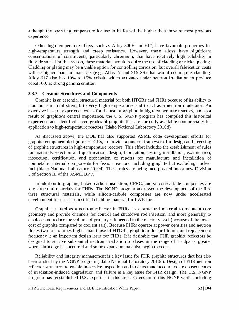
FHR Functional Requirements and LBE Identification White Paper 52 | 104
although the operating temperature for use in FHRs will be higher than those of most previous experience.
Other high-temperature alloys, such as Alloy 800H and 617, have favorable properties for high-temperature strength and creep resistance. However, these alloys have significant concentrations of constituents, particularly chromium, that have relatively high solubility in fluoride salts. For this reason, these materials would require the use of cladding or nickel plating. Cladding or plating may be a viable option for controlling corrosion, but overall fabrication costs will be higher than for materials (e.g., Alloy N and 316 SS) that would not require cladding. Alloy 617 also has 10% to 15% cobalt, which activates under neutron irradiation to produce cobalt-60, as strong gamma emitter.
3.3.2 Ceramic Structures and Components Graphite is an essential structural material for both HTGRs and FHRs because of its ability to
maintain structural strength to very high temperatures and to act as a neutron moderator. An extensive base of experience exists for the use of graphite in high-temperature reactors, and as a result of graphite’s central importance, the U.S. NGNP program has compiled this historical experience and identified seven grades of graphite that are currently available commercially for application to high-temperature reactors (Idaho National Laboratory 2010d).
As discussed above, the DOE has also supported ASME code development efforts for graphite component design for HTGRs, to provide a modern framework for design and licensing of graphite structures in high-temperature reactors. This effort includes the establishment of rules for materials selection and qualification, design, fabrication, testing, installation, examination, inspection, certification, and preparation of reports for manufacture and installation of nonmetallic internal components for fission reactors, including graphite but excluding nuclear fuel (Idaho National Laboratory 2010d). These rules are being incorporated into a new Division 5 of Section III of the ASME BPV.
In addition to graphite, baked carbon insulation, CFRC, and silicon-carbide composites are key structural materials for FHRs. The NGNP program addressed the development of the first three structural materials, while silicon-carbide composites are now under accelerated development for use as robust fuel cladding material for LWR fuel.
Graphite is used as a neutron reflector in FHRs, as a structural material to maintain core geometry and provide channels for control and shutdown rod insertion, and more generally to displace and reduce the volume of primary salt needed in the reactor vessel (because of the lower cost of graphite compared to coolant salt). Because FHRs operate at power densities and neutron fluxes two to six times higher than those of HTGRs, graphite reflector lifetime and replacement frequency is an important design issue for FHRs. It is desirable that FHR graphite reflectors be designed to survive substantial neutron irradiation to doses in the range of 15 dpa or greater where shrinkage has occurred and some expansion may also begin to occur.
Reliability and integrity management is a key issue for FHR graphite structures that has also been studied by the NGNP program (Idaho National Laboratory 2010d). Design of FHR neutron reflector structures to enable in-service inspection and to detect and accommodate consequences of irradiation-induced degradation and failure is a key issue for FHR design. The U.S. NGNP program has reestablished U.S. expertise in this area. Extension of this NGNP work, including

FHR Functional Requirements and LBE Identification White Paper 53 | 104
capabilities to fabricate and test nuclear graphite to cover FHRs, is an essential ingredient for FHR development. The use of graphite in FHRs is a key topic covered in the third FHR workshop.
Carbon-carbon and silicon-carbide composites are important structural materials for FHRs. The IRP baseline designs will not use ceramic composites as primary pressure boundary structural materials. Instead, these composites may be used to guide the primary coolant flow and control (but not prevent) bypass leakage. Where ceramic composites are used to guide the primary flow, instrumentation or periodic inspection methods will be provided to monitor leakage flows (for example, thermocouples monitoring the FHR core outlet temperature will have the capability to verify whether bypass flow remains within design limits). When ceramic composites are used for structural functions, these functions will be carefully defined and the capacity to perform these structural functions will be verified through testing and monitored using in-service inspection.
Carbon-carbon composites may be used to strengthen FHR plate fuels for fixed-fuel designs. Also, it will be desirable to use carbon-carbon composites to fabricate the core barrel structure for FHRs because of the smaller thermal expansion mismatch between carbon-carbon composites and graphite reflector blocks, compared to the thermal expansion of a metallic core barrel. The core barrel may also perform a structural function because it may provide some restraint for the radial graphite reflector blocks. These reflector blocks are likely to be designed to maintain structural integrity independent of the core barrel under DBEs (e.g., earthquakes), in which case the carbon-carbon composite core barrel would provide defense in depth. A key issue for FHR design will be to define the specific structural requirements for carbon-carbon composite structures and to assess their capability to perform these functions.
Silicon-carbide composite structures will have very high tolerance to neutron irradiation. The capability of silicon-carbide composite structures to accommodate high neutron doses make them logical materials to use for shutdown rod channels. In the FHR test reactor, silicon-carbide composite liners may be used to line shutdown rod channels in the graphite reflector blocks. Based on experience gained in a test reactor, silicon-carbide composite structures may then be used in additional structural functions in a commercial prototype FHR. In particular, the use of silicon-carbide composites for shutdown rod insertion channels could be highly attractive, because it could eliminate the need for a central graphite column in annular pebble bed core designs.
3.3.3 Building Structures Steel-concrete composite structures provide significant advantages for the construction of
modern reactor structures like the AP-1000 (Figure 3-3) because of their improved ductile behavior under high structural loading and their favorable characteristics for modular construction. The IRP decision to use steel-concrete composites for building structures supports a more fundamental goal, which is to encourage FHR designers to consider modularization in every element of their designs. To the maximum extent possible, FHR SSCs should be designed to be factory preassembled into modular units, which can be assembled at a plant site. Likewise, to the extent possible, equipment should be designed to be installed into subassemblies at the construction site, before heavy lifts place the subassemblies onto the reactor base mat. For

FHR Functional Requirements and LBE Identification White Paper 54 | 104
example, the design of the reactor cavity liner, cooling, and insulation systems should anticipate modular construction methods.
Also, FHR building structures should be designed to control the generation of vapors and gases and to control their venting paths under loading for BDBEs. In concrete for the reactor cavity structure, designers should avoid the use of limestone-based aggregate, which can generate large volumes of carbon dioxide when overheated, and instead use basaltic aggregate or other advanced additives (such as glass fiber reinforcing) that do not generate gas. Likewise the cavity liner plates should be designed with leak chases behind the plates that would collect any leaking water (if water is used for liner cooling) as well as steam that could evolve from the concrete if it is heated above 100°C, to provide a controlled path to collect the liquid in a drain tank and for venting of gases to the confinement filter system.
Figure 3-3. A Typical Steel-Concrete Structural Module Used in the AP-1000
The identification and selection of materials (or “constituents”) for FHRs involves key decisions that must trade off a variety of competing performance goals. These performance goals are directly related to the functional requirements defined for SSCs. Chapter 2 and Appendix A review these functional requirements; a primary objective of the third workshop is to develop criteria for selecting materials to be used in future FHRs.

FHR Functional Requirements and LBE Identification White Paper 55 | 104
4 Selection of FHR Licensing Basis Events
The fuel and coolant selection for FHRs provides the opportunity to develop a class of reactors with excellent safety characteristics that make them robust in responding to a wide range of postulated transient and accident scenarios. To demonstrate acceptable plant performance to regulators, each specific FHR design must include a safety analysis for a set of LBEs. A comprehensive set of LBEs for an FHR design establishes the basis for plant analysis, and a selected subset of these LBEs can be used to assess the characteristic response of the plant to a range of demands.
This chapter presents an approach for the selection of FHR LBEs that incorporates both deterministic safety principles and considerations of risk. This combination allows for the incorporation of knowledge developed through the use of probabilistic risk assessment (PRA) as the design matures and becomes more specific. The approach recommended here attempts to integrate the advantages of experiences in the licensing of LWRs as well as the NRC pre-application review of the GE S-PRISM fast reactor and HTGR concepts. In particular, the material developed for the pre-application review for the PBMR and NGNP provides a comprehensive approach to select LBEs for a new class of reactor with a limited experience base (Idaho National Laboratory 2010b; Zhao and Peterson 2007).
This chapter also presents a set of LBEs that should be used as a foundation for safety analysis of FHR designs as they develop. This set includes LBEs for use in pre-conceptual design, which are derived from a comprehensive review of systems in the current pebble and fixed-fuel FHR designs, as well as a preliminary set of bounding events that test the reactor response under several high-demand scenarios. The proposed set of events for FHR safety analysis should be incorporated into the development of specific designs through an iterative process to ensure that these designs include systems that are sufficient to meet the safety requirements in licensing, but do not incorporate further levels of redundancy that might place FHRs at an economic disadvantage with other reactor technologies that may have equivalent or lower levels of overall safety.
4.1 Regulatory Foundation
This section reviews NRC regulation and guidance relevant to the risk-informed selection of LBEs for advanced reactors such as FHRs. This material is drawn from the NGNP White Paper on LBE Selection (Idaho National Laboratory 2010b), which includes more detailed discussions on NRC regulations and the selection of TLRC. The discussion presented here is focused on the adoption of risk-informed methods within current NRC guidance and recent experience in the LBE selection process for non-LWRs. This section also reviews some special considerations for FHRs regarding the application of TLRC in the pre-conceptual design phase.
4.1.1 NRC Guidance on the Use of Probabilistic Risk Assessment NRC regulation requires the analysis of anticipated events and postulated accidents in the
preparation of a Final SAR under the guidance of the Standard Review Plan (NRC 1987) to demonstrate the plant safety case for a wide range of events. Events are categorized based on frequency into three categories: (1) normal operation, including anticipated operational

FHR Functional Requirements and LBE Identification White Paper 56 | 104
occurrences (AOOs); (2) off-normal events and DBEs; and (3) BDBEs, which include severe accidents and extensive plant damage events. Current requirements for analysis and acceptance criteria have some applicability for FHRs but are generally specific to LWRs.
For advanced reactors, the NRC has issued guidance that new reactors are required to demonstrate at least the same degree of safety demonstrated for LWRs with enhanced safety margins, including the use of simplified, inherent, passive, or innovative means to accomplish these goals (NRC 2008). The NRC staff also indicated that a risk-informed approach to the selection of LBEs should be incorporated into the licensing process. Specifically, the NRC staff recommended several actions to the Commission itself on the use of PRA to support the licensing basis (Vietti-Cook 2003):
• Modify the Commission’s guidance to put greater emphasis on the use of risk information by allowing the use of a probabilistic approach in the identification of events to be considered in the design, provided there is sufficient understanding of plant and fuel performance and deterministic engineering judgment is used to bound uncertainties
• Allow a probabilistic approach for the safety classification of SSCs
• Replace the single failure criterion with a probabilistic (reliability) criterion
• Expand the use of PRA to form part of the basis for licensing and thus put greater emphasis on PRA quality, completeness, and documentation.
These recommendations support the use for PRA in the selection of LBEs, underpinned by deterministic engineering judgment. These complementary analysis methods are integrated into the process outlined in the following subsections for the selection of FHR LBEs.
4.1.2 NRC Experience for Advanced Reactors While the main focus of NRC licensing and regulation is on LWRs, several instances of
regulatory interaction helped inform the LBE selection approach for FHRs and other classes of advanced reactors. NRC pre-application review for HTGR designs (including the Modular HTGR, PBMR, and NGNP) and the GE S-PRISM reactor provides important experience directly relevant to the development of the FHR. Details of these experiences can be found through publically available documents on the NRC website and are referenced in other sections of this white paper. Several outcomes that are particularly important for the selection of LBEs for FHRs are outlined below.
Selection of LBEs for the modular HTGR included a systematic, risk-informed approach that integrated PRA. In review of this material, the NRC staff noted that many regulatory criteria developed for LWRs were applicable to the modular HTGR and that these criteria should be used to ensure an equivalent level of safety to the current-generation LWRs (NRC 1989).
The pre-application review for PBMR and NGNP built on the experience from the modular HTGR and included a comprehensive, risk-informed approach to the selection of LBEs that incorporated engineering analysis and judgment. One issue, however, is the development of dose limits for BDBEs based on the frequency and consequence space. The NRC cautioned against the use of the Quantitative Health Objectives (NRC 1986) to define specific regulatory dose

FHR Functional Requirements and LBE Identification White Paper 57 | 104
limits because these limits are not defined by federal statute.1 The acceptable regulatory criteria for BDBEs, including severe accidents, remain unresolved and are likely to evolve based on the lessons learned from the events at Fukushima.
The pre-application material submitted in support of the GE S-PRISM design also included a risk-informed approach to the selection of LBEs. In review of the material, the NRC staff proposed an alternative approach to the selection of BDBEs based on a more conservative bounding event selection process (NRC 1994).
BDBEs may result in extensive plant damage. The management of accidents with extensive damage is also an important issue for design and licensing, including the development of guidelines analogous to the Severe Accident Management Guidelines (SAMG) and Extensive Damage Mitigation Guidelines (EDMG), which will be important for FHRs. Besides guidelines that provide procedures to mitigate the consequences of significant plant damage, instrumentation to monitor key plant state parameters must also be identified.
The NRC experience with review of advanced reactor design suggests that the determination of event sequences and acceptance criteria for BDBEs remains the area with the greatest uncertainty for the selection of LBEs in FHRs. The approach presented in the following subsections attempts to balance this uncertainty by incorporating a comprehensive, risk-informed strategy with appropriate bounding event selection and mitigation guideline development for early design phases. This approach is meant to be a graded strategy where risk-informed methods will eventually replace conservative deterministic methods as the experience base increases.
4.1.3 Special Considerations for FHR TLRC One issue that is unique to FHRs, discussed previously, is the large thermal margins to the
failure of TRISO particles, which significantly limit the scenarios for FHR accident sequences that may release radioactive material. The risk-informed selection of LBEs developed for the NGNP includes TLRC based on dose limits in relevant sections of the Code of Federal Regulations (Idaho National Laboratory 2010b). These limits may also be used in future FHR licensing efforts but are of more limited use in the early design phase because credible release sequences involving fuel (rather than circulating activity) are difficult to postulate.
Based on the limited scenarios for release of radioactive material from the fuel in FHRs, alternative proxies should be adopted in early design phases that provide more useful limits for design and safety analysis. Analysis work for FHR transients performed at UCB have incorporated the temperature of metallic structures as a design limit; this limit is a useful measure of confidence in the system geometry. These temperature limits should be defined based on time exposure for creep limits or reduced yield stress limits at elevated temperatures. The definition of these limits and other quantitative limits for FHRs were a major issue for the third workshop. Note that the temperature limits are not equivalent to TLRC but instead define a transition to analyzing severe accidents where system geometry and/or coolant inventory may be compromised. Further analysis will be needed to demonstrate acceptable releases based on the TLRC limits, and the equivalent of SAMGs and EDMGs will need to be developed to provide guidance on strategies to mitigate BDBEs where the FHR structural integrity and/or coolant inventory might be compromised. 1 Discussion with Dr. George Flanagan, Oak Ridge National Laboratory, at UCB, December 2011.

FHR Functional Requirements and LBE Identification White Paper 58 | 104
4.2 FHR Operating Modes and States
For a new reactor technology such as the FHR, it is important to define plant conditions and operating modes for the development of more detailed design and establishing functional requirements for SSCs under normal operating conditions. These states define the initial conditions for safety analysis of LBEs.
A conventional FHR is expected to have six general plant operating modes. These modes are analogous to those defined for the PBMR (Pebble Bed Modular Reactor 2006) as listed Table 4-1. These modes are ordered based on the overall demand on plant systems, which ranges from normal full-power operation to defueled maintenance conditions. This table also includes a postulated set of plant states for each mode that provide a wider range of plant operating conditions as more specific details of the design emerge. The principal difference in operating modes between the PBMR and the FHR is that there is only one shutdown mode for the FHR, because under shutdown conditions the reactor is maintained at a constant temperature (rather than having modes involving different temperatures). Each mode of FHR plant operation is briefly described in the following subsections.
Table 4-1. Preliminary Set of FHR Operational Modes and Plant States
Modes States
(5) Power Operation (5a) Normal Power Operation (5b) Reduced-Capability Operation
(4) Operational Standby
(3) Standby (3a) Main Power System Ready (3b) Reactor Ready
(2) Shutdown
(1) Fueled Maintenance (1a) Closed Maintenance (1b) Open Maintenance
(0) Defueled Maintenance (0a) Wet Maintenance (0b) Dry Maintenance
The set of operating states also includes normal plant transient conditions under power
operation that merit analysis to establish that the design can meet both the functional and safety requirements for these events. These operating states include normal startup, shutdown, and load-change transients. Figure 4-1 shows the expected system transitions between shutdown and normal power operation. The details of these normal transients will be specific to each FHR design, but each case will have generic issues that include the thermal response of reactor structures, temperature and xenon concentration-dependent reactivity effects, control element movement and reactivity worth requirements, and coupling to the power conversion unit (PCU).
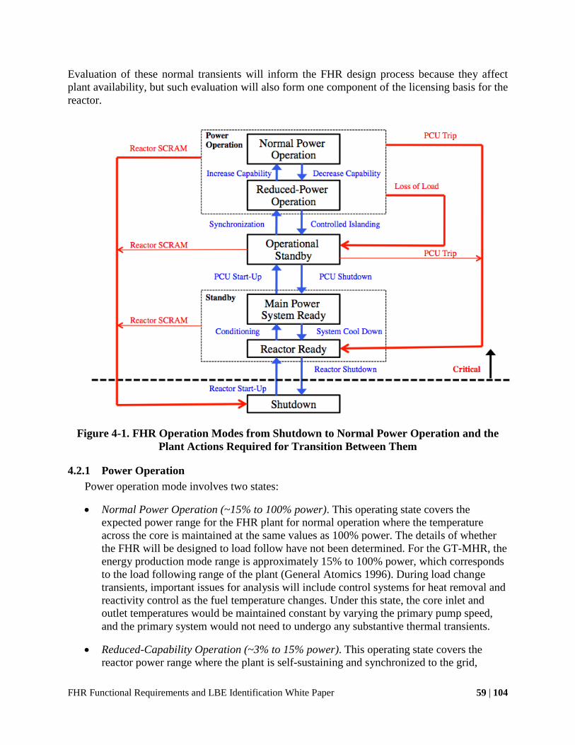
FHR Functional Requirements and LBE Identification White Paper 59 | 104
Evaluation of these normal transients will inform the FHR design process because they affect plant availability, but such evaluation will also form one component of the licensing basis for the reactor.
Figure 4-1. FHR Operation Modes from Shutdown to Normal Power Operation and the Plant Actions Required for Transition Between Them
4.2.1 Power Operation Power operation mode involves two states:
• Normal Power Operation (~15% to 100% power). This operating state covers the expected power range for the FHR plant for normal operation where the temperature across the core is maintained at the same values as 100% power. The details of whether the FHR will be designed to load follow have not been determined. For the GT-MHR, the energy production mode range is approximately 15% to 100% power, which corresponds to the load following range of the plant (General Atomics 1996). During load change transients, important issues for analysis will include control systems for heat removal and reactivity control as the fuel temperature changes. Under this state, the core inlet and outlet temperatures would be maintained constant by varying the primary pump speed, and the primary system would not need to undergo any substantive thermal transients.
• Reduced-Capability Operation (~3% to 15% power). This operating state covers the reactor power range where the plant is self-sustaining and synchronized to the grid,

FHR Functional Requirements and LBE Identification White Paper 60 | 104
estimated to be approximately 3% to 15% power. For this power range, the core inlet temperature would be held constant by the control systems while the outlet temperature would vary depending on the load requirements. This state includes a thermal transient as reactor systems rise from standby conditions to normal power operation temperature and must be managed to ensure acceptable thermal stresses in reactor SSCs. Procedures for heat removal and reactivity control will be required as temperatures increase in the primary coolant and fuel.
4.2.2 Operational Standby This operating mode covers the reactor power range where the plant is self-sustaining, up to
3% power, and the PCU is operational but not synchronized with the grid. Core inlet temperature would be held constant by the control systems.
4.2.3 Standby Standby mode involves two states:
• Main Power System Ready. This state covers the reactor power range up to approximately 3% power where the PCU systems are conditioned to startup temperatures. Primary system temperatures are held constant and maintained at the primary coolant core inlet temperature. Heat removal during plant conditioning would becontrolled though the normal shutdown cooling system.
• Reactor Ready. This state covers plant conditions from initial criticality to approximately 3% power where the loop remains at shutdown temperatures. Heat removal would be through the normal shutdown cooling system.
4.2.4 Shutdown This operating mode covers the subcritical plant conditions before startup or after shutdown.
The system remains at constant shutdown temperature. Thermal transients would be managed by the normal shutdown cooling system and by supplemental heating from the electric heating system if parasitic heat load exceeds the reactor decay heat production.
4.2.5 Fueled Maintenance Fueled maintenance mode involves two states:
• Closed Maintenance. This state covers plant maintenance conditions where the reactor remains in a shutdown state and the reactor cavity remains sealed. The system would remain isothermal at the maintenance temperature, which would be set based on maintenance requirements and with adequate margin against freezing. Conditions would be maintained through control systems that balance heat addition via decay heat and electric heaters and heat removal via the normal shutdown cooling system.
• Open Maintenance. This state covers plant maintenance conditions where the reactor cavity is opened for physical access to the reactor vessel and primary system. The reactor would remain in an isothermal shutdown condition at the design-specific hot maintenance temperature. Conditions would be maintained through control systems that balance heat addition via decay heat and electric heaters and heat removal via the normal shutdown cooling system.

FHR Functional Requirements and LBE Identification White Paper 61 | 104
4.2.6 Defueled Maintenance Defueled maintenance mode also involves two states:
• Wet Maintenance. This state covers all situations where the fuel has been removed from the reactor and the primary coolant remains in the system. Additional heat would provided in this state through the electrical heating system to prevent freezing. Additional salt may be added to the primary loop by the Primary Salt Inventory Control System to make up the fuel volume and ensure flow paths to the heaters are available. Control systems will be required to maintain isothermal conditions and limit stresses associated with thermal transients.
• Dry Maintenance. This state covers all situations where the fuel and coolant have been removed from the system for dry maintenance operations. Electrical heaters would be used to manage the thermal stresses as the system cools to the specified dry maintenance temperatures. This plant state also corresponds to the initial startup conditions before the first salt and fuel loading to the system. Operational procedures need to be developed for initial startup from dry conditions; activities include cavity heating, fuel and salt loading, and initial physics testing. Future designs will need to specify the appropriate loading order for the fuel and coolant. In the dry maintenance state, loads from the primary system that are normally taken through the upper-core structures will shift to the reactor vessel as positive buoyancy is lost.
4.3 FHR LBE Selection Approach
This section outlines an approach for the selection of LBEs that incorporates both risk-informed and performance-based analysis with deterministic judgment and analysis. This approach incorporates components of the LWR licensing experience base with proposed probabilistic methods that are appropriate for a new reactor class such as FHRs. The general approach is described in the following section, followed by more detailed descriptions of the selection approach for AOOs, DBEs, and BDBEs. Finally, this section includes a discussion of the iterative approach for LBE selection that can use safety requirements to inform the functional and reliability requirements as a specific FHR design matures.
4.3.1 LBE Selection Process Overview The design process for FHRs seeks to develop a systematic methodology to incorporate
regulatory, stakeholder, and end-user requirements. This process includes the combination of a risk-informed approach to the selection of LBEs with a deterministic approach for the selection of bounding events that address the uncertainties for a new reactor class with a limited experience base.
Based on the approach from the NGNP program, the definition of LBEs that the workshop participants adopted is events derived from the FHR technology and plant design that are considered by the licensing process and are used to derive design-specific performance requirements from SSCs (Idaho National Laboratory 2010b). The FHR is currently in a pre-conceptual design phase for which there are numerous systems that can be incorporated to meet general safety and licensing requirements, as discussed previously in this white paper. These

FHR Functional Requirements and LBE Identification White Paper 62 | 104
systems can be used to form the basis for the identification of events and evaluation of event sequences.
Similar to the NGNP process, this method includes a combination of deterministic and probabilistic methods, but incorporates some additional flexibility that is appropriate for the current status of the FHR design. The LBE selection process for FHRs includes a set of characteristic SSCs that demonstrate defense in depth for the system but is not prescriptive in which SSCs are required and does not suggest which systems should be classified as safety-related for licensing purposes. These classifications should be determined later in the development process so that reactor designers can incorporate analysis specific to their reactor. This approach does not seek to generate prescriptive requirements for FHR designs because designers may determine that SSCs used in this analysis may not require safety classification or may not be necessary to meet the design-specific licensing requirements.
4.3.2 Risk-Informed Approach for AOOs and DBEs The method to select AOOs and DBEs for FHRs closely resembles the risk-informed process
proposed for the HTGR in the NRC pre-application review of both the PBMR and NGNP (Idaho National Laboratory 2010b; Zhao and Peterson 2007). This process incorporates a PRA methodology to evaluate the safety characteristics of preliminary designs and to determine the appropriate TLRC that need to be satisfied for each class of events. The use of PRA also allows for a systematic evaluation of plant event sequences, which helps to ensure that a complete set of events is considered in the accident analysis.
To create a set of risk-informed event categories, the LBE selection process must develop a set of plausible initiating events. Workshop participants selected initiating events for FHRs based on a combination of informed judgment and a hierarchical decomposition to develop failure modes for major reactor systems. The use of a hierarchical system decomposition is useful at the current design phase to ensure the most complete possible set of events given the limited number of specific design decisions. The focus of this process in the workshop was therefore based on the failure modes of reactor systems as initiating event classes and did not seek to identify specific mechanisms that lead to the failure, which can be complex (and require analysis using fault trees). For example, the loss of the PCU was treated as a single initiating event, even though it can be caused through a large variety of system or component failures that would involve a very complex fault tree. The use of engineering analysis and judgment was incorporated after the large set of initiating events was developed to exclude events that are not plausible so that event sequences can be developed for all the significant initiating events.
The experts then categorized the set of initiating events developed from the system decomposition for the FHR based on the types of initiating events used by the NRC in the Standard Review Plan for LWRs (NRC 1987), which are listed in Table 4-2. Note that while the initiating events will be different based on the reactor technology, these categories are technology-neutral and can be applied to the FHR. This approach is therefore able to integrate elements of the existing LWR review framework. This set of event categories is also useful to evaluate the relative importance of FHR event sequences for different FHR design options and also in comparison to other reactor types. Each category will include similar event sequences in terms of system response to the required safety functions but will diverge in the specific systems

FHR Functional Requirements and LBE Identification White Paper 63 | 104
that will be available depending on the initiating event. Table 4-3 gives a preliminary list of FHR initiating events for each accident category.
Table 4-2. Initiating Event Categories for LWRs, Adapted from NUREG 800 (NRC 1987)
(1) Increase in heat removal by the secondary system
(2) Decrease in heat removal by the secondary system
(3) Decrease in reactor coolant system flow rate
(4) Reactivity and power distribution anomalies
(5) Increase in reactor coolant inventory
(6) Decrease in reactor coolant inventory
(7) Radioactive release from a subsystem or component
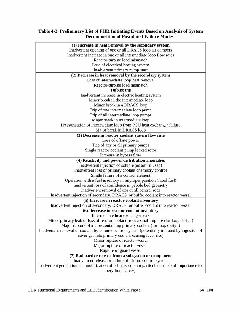
FHR Functional Requirements and LBE Identification White Paper 64 | 104
Table 4-3. Preliminary List of FHR Initiating Events Based on Analysis of System Decomposition of Postulated Failure Modes
(1) Increase in heat removal by the secondary system Inadvertent opening of one or all DRACS loop air dampers
Inadvertent increase in one or all intermediate loop flow rates Reactor-turbine load mismatch
Loss of electrical heating system Inadvertent primary pump start
(2) Decrease in heat removal by the secondary system Loss of intermediate loop heat removal
Reactor-turbine load mismatch Turbine trip
Inadvertent increase in electric heating system Minor break in the intermediate loop
Minor break in a DRACS loop Trip of one intermediate loop pump Trip of all intermediate loop pumps
Major break in intermediate loop Pressurization of intermediate loop from PCU heat exchanger failure
Major break in DRACS loop (3) Decrease in reactor coolant system flow rate
Loss of offsite power Trip of any or all primary pumps
Single reactor coolant pump locked rotor Increase in bypass flow
(4) Reactivity and power distribution anomalies Inadvertent injection of soluble poison (if used)
Inadvertent loss of primary coolant chemistry control Single failure of a control element
Operation with a fuel assembly in improper position (fixed fuel) Inadvertent loss of confidence in pebble bed geometry
Inadvertent removal of one or all control rods Inadvertent injection of secondary, DRACS, or buffer coolant into reactor vessel
(5) Increase in reactor coolant inventory Inadvertent injection of secondary, DRACS, or buffer coolant into reactor vessel
(6) Decrease in reactor coolant inventory Intermediate heat exchanger leak
Minor primary leak or loss of reactor coolant from a small rupture (for loop design) Major rupture of a pipe containing primary coolant (for loop design)
Inadvertent removal of coolant by volume control system (potentially initiated by ingestion of cover gas into primary coolant causing level rise)
Minor rupture of reactor vessel Major rupture of reactor vessel
Rupture of guard vessel (7) Radioactive release from a subsystem or component
Inadvertent release or failure of tritium control system Inadvertent generation and mobilization of primary coolant particulates (also of importance for
beryllium safety)

FHR Functional Requirements and LBE Identification White Paper 65 | 104
The use of engineering judgment and systematic decomposition enables the introduction of risk-informed methods at an early stage in the iterative design process. The use of PRA in the selection of LBEs is based on the methods developed for the pre-application review for PBMR and NGNP (Idaho National Laboratory 2010b; Zhao and Peterson 2007) and includes the following benefits, as stated in the NGNP White Paper on LBE Selection:
• Using PRA to aid in the development of events that are included in the licensing basis maximizes the probability of establishing a comprehensive safety basis. By its nature, PRA development is a rigorous process that considers the comprehensive performance of the facility design.
• Probabilistic methods for event selection, safety classification of SSCs, special treatment identification, and integration of defense-in-depth strategies will seek to optimize the safety characteristics of the reactor design.
• The PRA provides a rational approach for identifying, understanding, and addressing uncertainties.
These benefits apply for the use of PRA in the FHR design process though the quantification of both frequencies and consequences of potential accident sequences. At the current state of development, the quantities that would be used in a PRA include large uncertainties because there is little or no operating experience for the proposed systems. Instead, the process can be used to estimate reliability requirements for engineered systems (discussed later in Subsection 4.3.5) so that event sequences can be assigned to a category by the design team. This assignment also allows the design process to eliminate sequences from the required analysis though the selection of systems with designated reliability requirements. The future development of a PRA for FHRs will mature in conjunction with the specific design selections.
The conceptual design phase PRA suggested for FHRs would categorize events based on the anticipated frequency using assigned, rather than observed, system reliability requirements. The categorization for AOOs, DBEs, and BDBEs for FHR makes use of the approach developed for NGNP:
• AOOs are defined as events that are anticipated to occur within the lifetime of a single plant and span a frequency range of several per reactor year to a conservative lower bound of one per 100 reactor years.
• DBEs include events that are anticipated to occur within the lifetime of a reactor fleet and span a frequency range from the AOO lower frequency limit to a conservative lower bound of one per 10,000 reactor years.
• BDBEs are events that are not expected to occur in the lifetime of a reactor fleet but merit analysis to ensure that there is acceptable risk to the general population. Such events have a frequency range that extends to one per 1,000,000 reactor years, but the NGNP uses a lower bound of one per 2,000,000 reactor years to ensure that sequences just below the threshold are included. Events with lower frequencies are not viewed as contributing significantly to the overall system risk and do not require analysis.

FHR Functional Requirements and LBE Identification White Paper 66 | 104
Integrating each event category into a frequency-response curve (Figure 4-2) shows the regulatory limits, in terms of total effective dose equivalent (TEDE) at the exclusion area boundary (EAB), for each event category.
Figure 4-2. Frequency-Consequence Chart from NGNP Program with TLRC Limits (Idaho
National Laboratory 2010b)
The approach presented here for the FHR conceptual design phase does not include analysis of exposure dose because this stage of analysis introduces a significant amount of uncertainty, and the large margin-to-fuel thermal failure makes it difficult to define credible release pathways of radioactive material from the FHR fuel. The most likely pathways are expected to instead involve circulating activity, for example a failure of the tritium management system or the release of fission product gases from defective particles or tramp uranium in the fuel. These pathways are design specific and will require study later in the FHR development process. The current effort seeks only to classify postulated accident sequences in general terms.
The approach classifies event sequences based on the anticipated frequency determined through the use of event trees. Figure 4-3 shows a sample event tree for an FHR in response to the loss of the PCU, with one AOO, one BDE, and two BDBEs. Two sequences fall below the minimum frequency threshold for analysis. In this event sequence, heat removal decreases in the secondary system, which causes an increase in primary coolant temperature. The detection of off-normal conditions initiates reactor scram by the reactivity control system or reserve shutdown system. Decay heat is removed by the normal shutdown cooling system that may operate in forced or natural circulation modes. Failure of the normal shutdown system would result in decay heat removal by natural circulation in the DRACS loops. The probabilities listed

FHR Functional Requirements and LBE Identification White Paper 67 | 104
are notional and would need to be estimated based on fault tree analysis and a set of assumptions on component reliability.
Figure 4-3. Sample FHR Event Tree for Loss of the PCU
The right-hand columns of the event tree in Figure 4-3 show that this initiating event has one AOO sequence, one DBE sequence, two BDBE sequences, and two sequences that fall below the minimum frequency threshold. In this case, the AOO includes the initiating event and the proper functioning of all reactor systems, and the DBE is the protected loss of intermediate loop heat removal. For the notional event probabilities listed in the figure, neither case is expected to result in the release of any radioactive material and both should be able to demonstrate compliance with the TLRC.
4.3.3 Bounding Events Approach for BDBEs The approach for the selection of BDBEs presented here diverges from the risk-informed
methodology for AOOs and DBEs and is based on a more conservative deterministic approach rooted in the NRC licensing process for LWRs and the NRC review of pre-application material submitted in support of the licensing of the GE S-PRISM in the mid-1990s. This approach includes the selection of a series of bounding event categories that place significant demands on the safety systems of the reactor design and envelope a wide range of BDBEs. This approach is recommended here for the early development stage of the FHRs because it is directly applicable to new reactor designs with limited operational experience and the robust inherent safety characteristics of the reactors. Note that the approach diverges from historical bounding event analysis in the potential use of portable equipment under SAMGs and EDMGs to mitigate consequences for events where the plant damage state is uncertain. Risk-informed methods for BDBE classification may be integrated at future design stages when validation and reliability data might be available from a test reactor and component test facility.
In its review of the S-PRISM pre-application material, the NRC staff hesitated to accept the risk-informed approach for BDBEs submitted by GE (NRC 1994). In NUREG 1368, the staff indicated that “PRA can provide useful insights into event selection but that engineering judgment must ultimately be relied upon in the event selection to account for uncertainties.” The staff outlined five major concerns regarding uncertainty:

FHR Functional Requirements and LBE Identification White Paper 68 | 104
• The limited performance and reliability data for the critical systems, mainly the passive decay heat removal
• The lack of final design, which limits identification of initiating events, dominating sequences, and equipment reliabilities
• The incomplete state of supporting technology and analytical tools relevant to the new designs
• Extrapolation of research and development results to a full-size unit
• Significantly less design, construction, and operating experience compared to experience with LWRs.
Based on this concern, the NRC staff developed a set of bounding events for the S-PRISM (which also apply more generally for SFRs) “whose purpose is to account for uncertainties in design and reliability and acknowledge the difficulty in being able to identify, particularly at [the conceptual] state of design, all failure modes of a system or component.” Each of these concerns would apply to the current development of FHRs. Therefore, this white paper suggests a similar approach for the selection of BDBEs for the FHR that incorporates a conservative set of bounding events.
The preliminary types of bounding events presented here are analogous to those developed by the NRC staff for S-PRISM and are rooted in the guidelines for the deterministic analysis of accidents for LWRs in NUREG-800 (NRC 1987). The assumptions used for the selection of FHR bounding events are the same as those used in NUREG-1368 (NRC 1994):
• Select worst-case plant states (specified by system pressure, temperature, flow rate, etc.) as initial conditions for the challenges of the safety functions.
• Assume non-safety-grade equipment fails (either as an initiator or in response to the initiating event) in a way that exacerbates the accident to the maximum degree physically possible, unless a lesser degree can be justified. This approach will account for any uncertainties caused by using commercial-grade procurement and construction and the lesser operational surveillance associated with the non-safety grade designation.
• Assume failure of unique safety-grade equipment for a period of time (bounds uncertainties in failure probabilities of safety-grade equipment).
• Allow a reasonable time (consistent with emergency planning provisions) to recover safety-grade equipment where no plant damage has occurred (ATWS, station blackout, loss of all cooling).
• Assume multiple human errors or other initiating events consistent with events that have actually occurred.
• Ensure at least an equivalent challenge to that applied to LWRs.
Note that this approach does not seek to constrain future FHR design options by designating which systems are required or should be classified as safety related. Therefore, the development of a set of bounding events for a specific FHR design would require an evaluation to determine if the proposed list is still applicable or if additional bounding events merit consideration.

FHR Functional Requirements and LBE Identification White Paper 69 | 104
The following list includes a set of eleven bounding events that workshop experts suggested for the FHRs. These events put severe tests on the reactor safety systems and are all considered to be events in the BDBE frequency range or lower.
1. Unprotected transient overpower events. Assume a worst-case control rod withdrawal event. Assume that all control rods remain full out (at mechanical stops) for an extended time and then the reactor is scrammed. Analyze this event for three cases of a single module:
a. All forced cooling remains functional. b. All forced cooling is lost at the time the control rods are withdrawn. Primary
pumps trip, as called for if the reactor protection system detects off-normal conditions.
c. All forced cooling is lost at the time the control rods are withdrawn. Primary pumps remain on for the duration of the transient.
2. Station blackout. Assume that a scram occurs and natural circulation cooling is the only available mode of cooling for all modules on the site. Assume that an extended time passes before AC power is restored.
3. Protected loss of heat sink (LOHS). From full-power conditions, assume that all cooling via the normal cooling system is lost (loss of intermediate loop). Assume the reactor scrams as soon as the reactor protection system detects off-normal conditions. Analyze the event for cases where the DRACS heat removal capability is limited for an extended time.
4. Unprotected LOHS. From full power conditions, assume that all cooling via the normal
cooling system is lost (loss of intermediate loop). Reactor does not actively scram. Primary pumps remain on for the duration of the transient. Analyze until peak temperature or 12 hours have passed. (Note that this bounding event includes the failure of multiple systems that may be safety-related or merit special treatment, including the normal shutdown cooling system and control signals for primary pumps. Therefore, this event likely exceeds the requirements for bounding events, and analysis may not be required depending on the system classification in the specific FHR design. This event is not commonly studied for HTGRs or SFRs.)
5. Protected loss of forced circulation (LOFC). From full power conditions, assume the reactor scrams as soon as the reactor protection system detects off-normal conditions for a LOFC. Analyze the event for two cases:
a. Assume that the pumps are tripped and begin to coastdown. Assume that the DRACS heat removal capability is limited for an extended time.
b. Assume that the flow through one pump stops suddenly and the others continue to operate normally. Assume that the DRACS heat removal capability is limited for an extended time.
6. Unprotected LOFC. Assume an unscrammed LOFC on one module,and analyze the event for two cases:

FHR Functional Requirements and LBE Identification White Paper 70 | 104
a. Assume that the flow through one pump stops suddenly and the others continue to operate normally. Analyze the event until new equilibrium power and flow rates have been established.
b. Assume that the pumps are tripped and begin to coastdown. Assume one of the pumps does not coastdown and ceases pumping instantaneously.
7. Large loss of primary coolant. Assume a large rupture of the reactor vessel (pool design) or complete break of a single cold-leg pipe (loop design).
8. Overcooling. From full power conditions, assume a loss of heat removal to the PCU. Assume the reactor scrams as soon as the reactor protection system detects off-normal conditions. Pumps operate in a configuration that maximizes heat removal from the primary coolant. The normal shutdown cooling system and DRACS loops operate at full capacity. Electric heaters are not available. Analyze for 12 hours. (Note that the blockage of the DRACS loop for LOHS and LOFC effectively evaluates the potential impact of transients with freezing.)
9. Flow blockage. Assume blockage of flow to or from one fuel assembly (fixed-fuel
design).
10. Failure of hold-down structures. Assume a single failure in the upper-core hold-down structures that leads to a loss of geometry for the reactor graphite internals. [Note that this event will depend heavily on the specific plant design and is not practical to study in early design phases. The likely sequence of events under this scenario would have significant overlap with other transients where heat removal pathways are restricted or there is a significant change in plant geometry (e.g., primary vessel rupture).]
11. External events. Evaluate external events that exceed those traditionally analyzed as DBEs in a manner consistent with their application to current-generation LWRs. Severe external events that could merit site-specific study include earthquakes, flooding, tsunami, hurricane, and aircraft impact.
This selection of the preliminary set of bounding events for FHRs is based on a highly
conservative approach used in the licensing approach for LWRs. Many of these cases rely on the fundamental characteristics of the selected materials and even the failure of passive systems. For detailed designs, these events may be more conservative than required in the safety analysis, and a subset may need to be used in the licensing process.
One important distinction between the analyses of bounding events for the FHR and the historic licensing of LWRs is the adoption of best estimate plus uncertainty methods for the analysis of reactor transients. Modern analysis and simulation methods will be used to design and license FHRs; these methods can account for more realistic system response to initiating events. In these scenarios, the inherent characteristics of the fuel and materials for FHRs should reduce the consequences of the most severe accident sequences relative to the existing fleet of LWRs. For these conservative bounding events, the primary objective is to maintain public health and safety, and the plant would likely not be in acceptable condition for a future restart. A complete PRA analysis for FHRs would likely generate a more realistic, risk-informed set of

FHR Functional Requirements and LBE Identification White Paper 71 | 104
BDBEs that can be used in the design process to develop effective investment protection strategies where plant restart may be possible for BDBEs.
4.3.4 Lessons from Fukushima for Severe External BDBEs The deterministic approach to BDBEs described in Section 4.3.3 above is based on an
approach that was viewed favorably by the NRC in the mid-1990s for new reactor technologies. Much of the logic for this conservative approach is still relevant for non-LWRs for internal events, but experience at the Fukushima Daichi nuclear plant suggests that a different approach may be required for the analysis of externally initiated BDBEs. Under plant conditions with significant system damage and common failures generated by external events, the bounding event approach fails to take into account the actions of plant operators to mitigate damage and offsite releases in the face of large uncertainties in plant condition. This section discusses some measures that may provide improved defense in depth and reduced consequences in response to external BDBEs.
One important lesson from the events at Fukushima is that severe external events can introduce large uncertainties in plant conditions, which can be further exacerbated by the unavailability of adequate instrumentation under station blackout conditions. The response of operators in such conditions is not captured in the conservative bounding event approach because of defined assumptions about the duration of the events and which systems are available. Actual response in such conditions would be determined by operator decisions based on the available knowledge of plant conditions and the availability of plant systems or equipment transported to the site. These actions will be guided by the SAMGs and EDMGs, which need to be integrated into the licensing review for external BDBEs. Maintaining adequate measurements of plant conditions should also receive special consideration so that proper actions can be taken based on the severe accident guidelines.
Another important lesson from the events in Japan is the importance of the capability to provide standard external connections for power or cooling fluid if plant systems are left in a non-functional state. The capability to transport equipment to the reactor site by air has been implemented at many reactor sites in the U.S. as a response measure against external threats but could be of equal importance in severe external events where physical access on the ground may be limited. The detailed design of FHRs may incorporate the capability to use water injection to remove heat if the DRACS chimneys become obstructed or if additional salt cannot be injected into the reactor cavity to ensure that faulted salt levels remain above the active core region. Design of such systems would need to ensure that they do not create a significant release pathway risk and should be integrated into the PRA. The NRC is currently in the process of quantifying the benefits of these portable systems in severe accident analysis. The recently issued draft of NUREG 1935 shows that these emergency capabilities can have significant benefits for LWRs and reduce the cases of core damage to only a small subset of the most severe events (Chang et al. 2012).
For severe external BDBEs, it is important to consider some of the unique inherent safety capabilities of FHRs relative to other reactor technologies. FHRs provide an extremely large thermal margin to fuel failure and a low-pressure inert coolant. Fluoride salts also have high solubility for most fission products, including cesium-137, which is the primary isotope associated with long-term land contamination from both Chernobyl and Fukushima. The use of

FHR Functional Requirements and LBE Identification White Paper 72 | 104
fluoride salts could allow the potential for a different approach to severe accident analysis in which the primary objective is to minimize the health consequences from the release of radioactive material and the secondary objective is to minimize the disruptions caused by land contamination. Under this alternative approach, design decisions can be made to minimize, and potentially eliminate, the aerial pathways of radioactive material that would lead to short-term consequences beyond the reactor site. This approach meets leads to three key design objectives:
• Minimize peak temperature. Under severe accident conditions, plant geometry cannot be guaranteed and heat must be removed through a combination of conduction and natural circulation, which will increase the temperature of the primary reactor system and reactor building. Heat removal pathways via building structures to the ground and atmosphere may be designed to maintain fuel temperatures below 1600 °C and prevent the release of radioactive material from the fuel.
• Minimize gas generation. Gas generation, especially non-condensable gases, caused by high temperatures acts as primary means to disperse radioactive material into the atmosphere before dispersion into the surrounding area. Gas generation, particularly carbon dioxide from concrete, can be reduced by material selection and may be sufficient to eliminate aerial pathways for radioactive material.
• Maintain coolant inventory. In the event of a release of radioactive material from fuel, adequate coolant inventory to cover the fuel provides a significant sink for many fission products, including cesium-137. This design is inherently different from that of LWRs and offers a possibility for no long-term consequences from offsite releases.
Note that work to study severe accident conditions for FHRs has been limited, and design choices to eliminate BDBE consequences may be determined to be unnecessary or impractical. However, the possible elimination of offsite consequences appears to be unique to the combination of fuel and coolant in FHRs and merits consideration.
4.3.5 Iterative Approach for Design and System Reliability Requirements The selection process for LBEs presented in this white paper is designed to start the
development of a credible set of accident sequences that can be used in a future licensing process, but it is also intended to provide feedback for the design of the FHR concept. This feedback can be used to inform the safety classification of SSCs and also to incorporate system reliability requirements into the design process.
The safety classification of SSCs can have important implications on the development and operation of a new reactor. The risk-informed LBE selection process helps to demonstrate through PRA what systems may be required to ensure an acceptable end state for an accident sequence and, thus, which systems might require classification for safety-related or other special treatment. The PRA methodology also demonstrates qualitatively the layers of defense in depth incorporated into the design, as multiple system failures are required to reach unacceptable end states. This iterative process mirrors the NGNP LBE selection process.
The introduction of PRA into the pre-conceptual phase of LBE selection can also inform the system functional reliabilities required to simplify the LBEs needed for analysis in the licensing process. Figure 4-4 shows a modified event tree for the loss of the PCU that was shown earlier

FHR Functional Requirements and LBE Identification White Paper 73 | 104
to demonstrate the classification of LBEs by sequence frequency. In this event tree, the failure probability of the forced circulation mode Normal Shutdown Cooling System (highlighted) is determined to be the highest value, so that the frequency of a subsequent failure of the DRACS falls below the minimum credible threshold of 5x10⁻⁷. Note that also modifies the classification of sequences II and III to more frequent event categories than in Figure 4-3.
Figure 4-4. Modified Event Tree for Loss of the Power Conversion Unit.
Although the probabilities in Figure 4-4 are used for demonstration purposes, this approach allows for the reactor designer to define functional reliability requirements for different systems so as to simplify the analysis that may be required for licensing purposes. These reliability requirements may also demonstrate the need to add more diversity into the event sequence or to remove systems that may not be necessary. In addition, the reliability requirements may also inform the necessary redundancy for certain systems. For example, if a system failure rate better than 10-2 per demand is required for the Normal Shutdown Cooling System, this target reliability can inform how many redundant loops may be needed based on an analysis of the failure rate for a single loop. This information allows the integration of licensing requirements into the design process, while seeking to optimize the balance of system simplicity and redundancy.

FHR Functional Requirements and LBE Identification White Paper 74 | 104
References
American Nuclear Society. 2011. Nuclear Safety Design Process for Modular Helium-Cooled Reactor Plants. La Grange Park: American Nuclear Society.
Blandford, E. D. 2008. “Risk-informed Design Guidance for Advanced Reactor Concepts: A Case Study of the Pebble Bed Advanced High Temperature Reactor”. University of California, Berkeley.
Blandford, E. D., E. Keldrauk, M. Laufer, M. Mieler, J. Wei, B. Stojadinovic, and P. F. Peterson. 2009. Advanced Seismic Base Isolation Methods for Modular Reactors. Berkeley: University of California, Berkeley.
Blandford, E. D., and P. F. Peterson. 2008. “A Novel Buoyant Shutdown Rod Design for the Passive Reactivity Control of the PB-AHTR.” In 4th International Topical Meeting on High Temperature Reactor Technology. Washington, D.C.
Chang, R., J. Schaperow, T. Ghosh, J. Barr, C. Tinker, and M. Stutzke. 2012. State-of-the-Art Reactor Consequence Analyses (SOARCA) Report. Rockville, MD: U.S. Nuclear Regulatory Commission.
Cisneros, A. T, E. Greenspan, and P. F. Peterson. 2010. “Use of Thorium Blankets in a Pebble Bed Advanced High Temperature Reactor.” In International Congress on Advances in Nuclear Power Plants 2010, 1:261–269. San Diego: American Nuclear Society.
Cisneros, A. T., R. O. Scarlat, M. Laufer, E. Greenspan, and P. F. Peterson. 2012. “Pebble Fuel Design for the PB-FHR.” In International Congress on Advances in Nuclear Power Plants. American Nuclear Society.
Collins, J. W., J. M. Beck, E. O. Opare, and L. F. Pincock. 2008. NGNP – Creating Validated TRL and TDRMs for Critical Systems , Subsystems , and Components. Idaho Falls: Idaho National Laboratory.
Fei, T., D. Ogata, K. Pham, M. Solom, C. Zhao, C. Xu, A. Cheng, et al. 2008. A Modular Pebble-Bed Advanced High Temperature Reactor. Berkeley: University of California, Berkeley.
Fleming, K. N. 2006. Defense-in-Depth Approach for the Pebble-Bed Modular Reactor. Pebble Bed Modular Reactor.
Forsberg, C., P. F. Peterson, and P. S. Pickard. 2003. “Molten-Salt-Cooled Advanced High-Temperature Reactor for Production of Hydrogen and Electricity.” Nuclear Technology 144 (3): 289–302. http://epubs.ans.org/?a=3446.

FHR Functional Requirements and LBE Identification White Paper 75 | 104
Forsberg, C. W. 2008. Next Generation Nuclear Plant Phenomena Identification and Ranking Tables (PIRTs) Volume 6 : Process Heat and Hydrogen Co-Generation PIRTs. Rockville, MD: U.S. Nuclear Regulatory Commission.
Gandrik, A. M. 2012. Assessment of High Temperature Gas-Cooled Reactor ( HTGR ) Capital and Operating Costs. Idaho Falls: Idaho National Laboratory.
Gehin, J. C., D. E. Holcomb, J. J. Carbajo, D. Ilas, A. T. Cisneros, V. K. Varma, D. F. Wilson, et al. 2010. Pre-Conceptual Design of a Fluoride- Salt-Cooled Small Modular Advanced High-Temperature Reactor (SmAHTR). Oak Ridge: Oak Ridge National Laboratory.
General Atomics. 1996. Gas Turbine-Modular Helium Reactor (GT-MHR) Conceptual Design Description Report. San Diego: General Atomics.
Gomez, J., M. Hay, J. Lee, and B. Tam. 2010. Design of Fuel Testing and Qualification Capsules for the Pebble Bed Advanced High Temperature Reactor. Berkeley: University of California, Berkeley, Thermal Hydraulics Laboratory.
Griveau, A., F. Fardin, H. Zhao, and P. F. Peterson. 2007. “Transient Thermal Response of the PB-AHTR to Loss of Forced Cooling.” In Global 2007. Boise.
Holcomb, D. E., F. J. Peretz, and A. L. Qualls. 2011. Advanced High Temperature Reactor Systems and Economic Analysis September 2011 Status. Oak Ridge.
IAEA. 2007. Proposal for a Technology-Neutral Safety Approach for New Reactor Designs. Vienna, Austria: International Atomic Energy Agency.
Idaho National Laboratory. 2009. NGNP System Requirements Manual. Idaho Falls: Idaho National Laboratory.
———. 2010a. Next Generation Nuclear Plant Structures, Systems, and Components Safety Classification White Paper. Idaho Falls: Idaho National Laboratory.
———. 2010b. Next Generation Nuclear Plant Licensing Basis Event Selection White Paper. Idaho Falls: Idaho National Laboratory.
———. 2010c. NGNP Fuel Qualification White Paper. Idaho Falls: Idaho National Laboratory.
———. 2010d. NGNP High Temperature Materials White Paper. Idaho: Idaho National Laboratory.
———. 2011. Next Generation Nuclear Plant Probabilistic Risk Assessment White Paper. Idaho Falls: Idaho National Laboratory.

FHR Functional Requirements and LBE Identification White Paper 76 | 104
Ingersoll, D. T., C. W. Forsberg, and P. E. MacDonald. 2007. Trade Studies for the Liquid-Salt-Cooled Very High-Temperature Reactor: Fiscal Year 2006 Progress Report. Oak Ridge: Oak Ridge National Laboratory.
Ingersoll, D. T., C. W. Forsberg, L. J. Ott, D. F. Williams, J. P. Renier, S. J. Ball, L. Reid, W. R. Corwin, and M. Vernon. 2004. Status of Preconceptual Design of the Advanced High-Temperature Reactor (AHTR). Oak Ridge: Oak Ridge National Laboratory.
Keiser, J R, J H DeVan, and E J Lawrence. 1979. “Compatibility of Molten Salts with Type 316 Stainless Stell and Lithium.” Journal of Nuclear Materials 85-86, Par: 295–298.
Macpherson, H. G. 1985. “The Molten Salt Reactor Adventure.” Nuclear Science and Engineering 90: 374–380.
NRC. 1986. Safety Goals for the Operations of Nuclear Power Plants: Policy Statement; Republication.
———. 1987. Standard Review Plan for the Review of Safety Analysis Reports for Nuclear Power Plants: LWR Edition. Vol. 0800. Rockville, MD: U.S. Nuclear Regulatory Commission.
———. 1989. Draft Preapplication Safety Evaluation Report for the Modular High Temperature Reactor. Rockville, MD: U.S. Nuclear Regulatory Commission.
———. 1994. Preapplication Safety Evaluation Report for the Power Reactor Innovative Small Module (PRISM) Liquid-Metal Reactor. Washington, D.C.: U.S. Nuclear Regulatory Commission.
———. 2005. Regulatory Structure for New Plant Licensing, Part 1: Technology-Neutral Framework. Rockville, MD: U.S. Nuclear Regulatory Commission.
———. 2007. Appendix A to 10 CFR 50 — General Design Criteria for Nuclear Power Plants.
———. 2008. Policy Statement on the Regulation of Advanced Reactors. Vol. 73.
Pebble Bed Modular Reactor. 2006. Technical Description of the PBMR Demonstration Power Plant. Pebble Bed Modular Reactor.
Peterson, P. F., and H. Zhao. 2006. “A Flexible Base-Line Design for the Advanced High- Temperature Reactor Utilizing Metallic Reactor Internals (AHTR-MI).” In , 8–9. Reno, NV: Proceedings of the International Conference on Advances in Nuclear Power Plants (ICAPP 06).
Powers, J. J., and B. D. Wirth. 2010. “A Review of TRISO Fuel Performance Models.” Journal of Nuclear Materials 405 (1): 74–82.

FHR Functional Requirements and LBE Identification White Paper 77 | 104
Rosenthal, M., P. Haubenreich, and R. Briggs. 1972. The Development Status of Molten-Salt Breeder Reactors. Oak Ridge: Oak Ridge National Laboratory.
Sandell, L. 2004. A Review of Radionuclide Release from HTGR Cores During Normal Operation. Vol. 3. Palo Alto: Electric Power Research Institute.
Shaffer, J. H. 1971. Preparation and Handling of Salt Mixtures for the Molten Salt Reactor Experiment. Oak Ridge: Oak Ridge National Laboratory.
Shropshire, D. E., K. A. Williams, W. B. Boore, J. D. Smith, B. W. Dixon, M. Dunzik-Gougar, R. Adams, and D. Gombert. 2007. Advanced Fuel Cycle Cost Basis. Idaho Falls: Idaho National Laboratory.
Silady, F. A. 2006. Safety Classification Of Structures, Systems, and Components for the Pebble Bed Modular Reactor. Pebble Bed Modular Reactor.
Silady, F. A. 2006. Licensing Basis Event Selection for the Pebble Bed Modular Reactor. Pebble Bed Modular Reactor.
Sims, R., and J. Nestell. 2012. Roadmap to Develop ASME Code Rules for the Construction of High Temperature Gas Cooled Reactors (HTGRS). Rev. 1. New York: ASME Standards Technology, LLC.
Uhlir, J. 2007. “Chemistry and Technology of Molten Salt Reactors--History and Perspectives.” Journal of Nuclear Materials 360: 6–11.
Vietti-Cook, A. 2003. “Staff Requirements -- SECY-03-0047 -- Policy Issues Related to Licensing Non-Light Water Reactor Designs”. U.S. Nuclear Regulatory Commission.
Williams, D. F., L. M. Toth, and K. T. Clarno. 2006. Assessment of Candidate Molten Salt Coolants for the Advanced High-Temperature Reactor (AHTR). Oak Ridge: Oak Ridge National Laboratory.
Zhao, Haihua, and Per F Peterson. 2007. “Optimization of Advanced High-Temperature Brayton Cycles with Multiple-Reheat Stages.” Nuclear Technology 158 (2): 145–157.
Zuber, N., G. E. Wilson, M. Ishii, W. Wulff, B. E. Boyack, A. E. Dukler, P. Griffith, et al. 1998. “An Integrated Structure and Scaling Methodology for Severe Accident Technical Issue Resolution: Development of Methodology.” Nuclear Engineering and Design 186 (1-2): 1–21.

FHR Functional Requirements and LBE Identification White Paper 78 | 104
Appendix A: FHR Subsystem Functional Requirements
This appendix presents a set of major functional requirements for FHR and systems and sub-systems level, which will guide the design and development of FHRs to ensure that regulatory and other requirements and performance goals are met. Because detailed designs for FHR systems have not yet been developed, the functional requirements also establish a set performance assumptions, on which analysis for phenomena identification and ranking will be based in Workshop 2.
The Next Generation Nuclear Plant (NGNP) program took a similar approach to documentation of the requirements for an NGNP plant, and the structure of NGNP requirements database was shown in Figure 1-5. The subject of this chapter addresses only the functional, operational, and technical requirements of FHR systems and sub-systems.
Section 2.1 presented the methodology for system decomposition for a generic FHR design. This system decomposition is used here for the definition of the functional requirements and it will subsequently be used in Workshop 2, for plausible phenomena identification. The FHR decomposition approach presented here was selected to be generic enough to encompass all of the FHR design options (e.g., pebble versus fixed fuel).
Functional requirement definition and phenomena identification are in fact iterative processes. We expect that updates to the functional phenomena tables will be warranted after the completion of Workshop 2. As background description of the key FHR sub-system, this chapter provides brief discussions of dominant phenomenology that pertains directly to the key functional requirements.
Functional requirement identification is also an iterative process with LBE identification. This workshop began with the definition of functional requirements, followed by LBE identification in Chapter 4. Subsequent iterations of this process will enable classification of the functional requirements by operational state, and identification of reliability requirements for each of the functions. System, sub-system, and components (SSC) safety classification will then follow.
Based on the consensus of the participants of the first FHR workshop and FHR advisory board, this section identifies major functional requirements for systems and sub-systems level, with a focus primarily on end-user (economics and investment protection, IP) and meeting the FHR SDC. When necessary other stakeholders requirements are considered with respect to such issues as safeguards (SG), nonproliferation (NP) and licensing. Table A-2 provides a preliminary list of plant-level functional requirements.

FHR Functional Requirements and LBE Identification White Paper 79 | 104
Table A-1. Top level requirements guiding the definition of system and subsystem functional requirements in this chapter
Safety Design Criteria (SDC)
Economics
Investment Protection (IP)
Safeguard (SG)
Physical Security (PS)
Table A-2. Preliminary list of plant-level functional requirements that the FHR design should satisfy
FHR Plant
Provide synchronized electric power to a large power grid including responding to load changes from the grid dispatcher
Provide energy at a price that is competitive with other power sources
Protect the health and safety of the public and plant workers
Provide for convenient operation and expeditious maintenance of the plant
Provide for investment protection
Provide for radwaste and hazardous material handling and disposal
Protect the environment
Provide for spent fuel storage
Provide for plant security
Provide a difficult path to proliferation
Provide features to facilitate eventual plant decommissioning
A.1 Functional Requirements for the Reactor System
The primary function of the reactor system is to provide heat for the power conversion system or the process heat application. The FHR reactor system uses a pool-type configuration with a low-pressure metallic reactor vessel with penetrations only the faulted salt free surface

FHR Functional Requirements and LBE Identification White Paper 80 | 104
elevation. Graphite reflector blocks ensure the internal geometry of the core, and provide neutron shielding to the reactor vessel, neutron reflection, and some moderation. The fuel system is housed inside the graphite blocks, and the coolant flow paths are provided by channels in the graphite blocks and/or the fuel assemblies. A core barrel structure surrounds the graphite blocks and guides the primary coolant flow from the IHX down an annular down-comer to the bottom of the reactor vessel. Because graphite is buoyant in the primary coolant, upper core support structures transfer the vertical loads from the reflector structures and fuel to the reactor vessel and the building structures. The upper core support structures also house additional instrumentation and equipment. The baseline primary coolant pumps are located at the top of the reactor, using cantilevered pump shaft traversing the free liquid surface and connecting to the shaft bearing assemblies and pump motor located above the upper core support structures. The key subsystems comprising the reactor system are summarized in Table A-3.
Table A-3. Reactor Subsystems
Reactor
Fuel
Primary coolant
Primary pump
Graphite structures
Core barrel & downcomer
Upper core support structures
In addition to the sub-system specific functional requirements in the subsequent sections, Table A-4 lists a generic set of functional requirements that must be considered in the design of each of the sub-sub-systems.

FHR Functional Requirements and LBE Identification White Paper 81 | 104
Table A-4. Generic functional requirements for the Reactor System
Generic Requirements and Considerations
Emergency preparedness
Post-event instrumentation
Instrumentation for online monitoring
Online maintenance
Maintenance and personnel access requirements
Replaceability requirements
Interface requirements
A.1.1 Functional Requirements for the Fuel Subsystem The functional requirements for the fuel subsystem pertain to the ensemble of fuel elements
and their associated supporting structures, the organization of the fuel elements in the core, the detailed design of the fuel elements, the detailed design of the coated particles that form the fuel, and the specific choice of nuclear fuel. These requirements equally apply across the range of design options for the fuel, such as fixed or pebble fuel, and whatever combination of TRU, LEU and thorium fuels are selected.
The baseline coated particle fuel is comprised of a fuel kernel enclosed in concentric layers of a buffer of porous graphite, pyrolitic carbon, silicon carbide, and a final layer of pyrolitic carbon. The porous buffer layer provides volume for the fission product gases, and the silicon-carbide layer is designed to withstand the thermomechanical stresses from temperature gradients, build-up of fission product gases, and other mechanical stress. Overall the silicon-carbide layer is designed to retain fission products, and the design of FHRs allows for uniquely large (several hundreds of degrees Celsius) thermal margins to the failure temperature of fuel particles (Powers and Wirth 2010; Sandell 2004).
These coated fuel particles are compacted in a graphite matrix to form the desired shape of the fuel element. The fuel element may contain an outer layer of inert graphite (pebble shell or fuel plate sleeve), to protect the fuel region from erosion and to prevent generation of dust that contains fission products or fuel particles. For mechanical strength, heat transfer, or other considerations, the fuel element may also contain other inert graphite regions.
The functional requirements for the fuel are summarized in Table A-5.
(1) The main function of the FHR to produce heat economically from the nuclear fuel in the fuel system.

FHR Functional Requirements and LBE Identification White Paper 82 | 104
The fuel must sustain a fission chain reaction to generate power (i.e. maintain criticality). Pebble-bed FHRs are designed to operate at steady-state with low excess-reactivity so that reactivity can be managed by continuous fuel recirculation and refueling using high-burnup fuel as a neutron poison rather than dedicated burnable poisons. Fixed fuel FHRs design for excess-reactivity at the beginning of cycle of each fuel loading. The excess reactivity at the BOC (and beginning of equilibrium cycle for multi-batch systems) must be manageable by burnable poisons and the reactivity control system at normal operating conditions as well as cold zero-power conditions.
(2) The requirement for economic power generation limits FHR fuel to designs that are feasible to manufacture at a commercial scale. This requirement limits the coated particle packing fractions, fuel kernel diameters and coated layer thicknesses to values fuel venders will be confident in fabricating at a commercial scale. Furthermore, a fuel quality assurance program must be developed to ensure the fuel meets the design specifications.
The enrichment levels of the fuel also effects manufacturability of the fuel. Fuel fabrication facilities must increase their criticality safety limits if they upgrade existing light water reactor enrichment facilities to enrichments above 5w% 235U. It is noteworthy that the new GE laser enrichment facility will be licensed to produce uranium enriched up to 8w%.
Finally, fuel venders must qualify their fuel for use in an FHR and this qualification process and associated lead-time must be considered in design of the FHR fuel system. Because FHR fuel has lower peak temperatures that HTGR fuel during normal operation, transients and accidents, appropriate reductions in qualification processes should be sought in the licensing of fuel fabrication facilities.
(3) Preliminary economics scoping studies have identified fuel costs as one of the main concerns for the FHR reactor.
The current fuel cost models for coated particle fuel compacts predict significantly higher costs per unit mass of nuclear fuel than for LWR fuel, do not account for specific fuel design parameters and are uncertain because no large scale production capacity exists (Shropshire et al. 2007).
Hand-fabrication batch-process manufacturing and tight quality control have resulted in high fuel costs for high temperature gas reactor (HTGR) fuel. However, it is envisioned that continuous manufacturing processes can be developed as the market for particle fuel expand and it has not been determined if the tight manufacturing tolerances for the HTGR are required for FHRs.
These fuel costs may be partially offset by going to higher burnups. High burnup can be achieved by using the highest permissible enrichment fuel and moderating the neutron spectrum to optimize the balance between fission and breeding while maintaining negative coolant void reactivity feedback.
(4) The fuel system must interface with the primary coolant system so it can remove the heat generated in the fuel.

FHR Functional Requirements and LBE Identification White Paper 83 | 104
The heat that is generated in each fuel particle kernel is transferred by conduction to the surface of the fuel particle, then again through conduction to the surface of the fuel element, and convected from the fuel element surface to the coolant. In the TRISO particle, the dominant resistance to heat transfer is the buffer layer, which has a low thermal conductivity that dependent on its porosity, burn-up, radiation damage and temperature.
At the fuel element scale, the resistance to heat transfer is the function of fuel element geometry and the thermal conductivity of the fuel and the non-fuel regions. Cracks or other undesired gaps in the fuel element, such as layer delamination, would increase the thermal resistance. The thermal conductivity of the graphite will be dependent on irradiation dose and temperature. Mechanical integrity of the fuel element is important, to ensure a predictable conduction path to the surface of the fuel element.
Convective heat transfer at the fuel element surface is a function of the geometry at the surface of the fuel element, and the geometry surrounding the fuel element which affects the thermal boundary layers formed on the fuel surface. The latter is dictated by the arrangement of the fuel in the core.
(5) The fuel must also interface with the fuel loading and unloading system.
In a pebble bed FHR, this requirement dictates that the fuel must be buoyant in the primary coolant, must be subcritical when being handled outside the core, must accommodate being moved either mechanically or hydrodynamically, must enable the fuel handling system to measure its burnup non-destructively and must minimize the probability of bridging or blocking the defueling channel of the core.
In a fixed fuel FHR, this requirement dictates that the fuel assemblies interface with a refueling and shuffling machine and must be subcritical when being handled outside the core. Because the position of each fuel element is known the burnup of each fuel element can be predicted with numerical simulation, so no burnup measurement system is required.
(6) The fuel system must provide a barrier to radionuclides generated in the fuel kernel.
The key barrier to radionuclide release is the silicon-carbide layer in the coated fuel particle. To maintain this fission product retention function, the coated fuel particle must stay intact. Thus, the coated layers must endure internal fission gas pressure, thermomechanical stresses from temperature gradients with radiation-degraded properties and the coated fuel particle design must protect against kernel migration (i.e. the amoeba effect) (Powers and Wirth 2010).
Furthermore, the fuel element must be resilient against crushing and other mechanical that could release fuel particle debris. The fraction of fuel elements that might fail mechanically must be kept small, and the means for recovering fuel element fragments from the coolant be provided in the reactor system design.
(7) The FHR fuel system must have a stable power level and power shape under all anticipated operating states, including startup. Negative temperature reactivity feedback mechanisms are required to maintain stable reactor operating dynamics. The Doppler broadening effect in 238U provides strong negative fuel kernel temperature reactivity coefficients. The graphite in the fuel element (coated particle layers, matrix and other fuel element graphite) does

FHR Functional Requirements and LBE Identification White Paper 84 | 104
not significantly contribute to the reactivity feedback, because the graphite density is not sufficiently sensitive to temperature and its moderating effect remains relatively constant with temperature change. The fuel must also be under-moderated under all operating conditions, so that the coolant void and temperature reactivity coefficients are negative (A. T. Cisneros et al. 2012; A. T Cisneros, Greenspan, and Peterson 2010; Gehin et al. 2010).
Establishing steady state is challenging for the pebble-bed variants of FHRs because the fuel is designed for equilibrium operation with a specific distribution of burnups (and thereby reactivities) in the pebbles. However, at the beginning of life only fresh pebbles with high reactivity and no burnup are available. The core loading and startup strategy envisioned for the PBMR entails diluting the core with inert graphite pebbles and increasing the concentration of fueled pebbles until criticality is reached (Pebble Bed Modular Reactor 2006). FHRs cannot employ this strategy because the fuel-to-moderator in the pebbles should remain undermoderated during core loading to maintain negative coolant void reactivity coefficients (so voiding the coolant makes the system even more undermoderated removing reactivity). Therefore, employing the PBMR strategy would involve passing through a fuel to moderator ratio with positive coolant void reactivity coefficients. Therefore it is expected that the FHR core loading process should involve starting with pebbles that contain neutron poisons (e.g., thorium or other neutron absorbers) and gradually substitute fuel pebbles, ensuring that criticality is approached from an undermoderated condition.
(8) For Anticipated Transient Without Scram (ATWS) response, the difference between the average fuel temperature and the bulk coolant temperature under power operation should be well understood, because this temperature difference is a key parameter governing ATWS response. Under beyond design basis conditions where the reactor heat sink is lost and/or forced circulation of the primary coolant is stopped and the reactor does not scram, the reactor undergoes a transient where the coolant and fuel reach temperatures sufficiently to shut down the fission process. Because the coolant is at a lower initial temperature than the fuel, the coolant temperature will rise, inserting negative reactivity, while as the fuel temperature drops providing positive reactivity insertion. The final equilibrium temperature reached by the coolant is important to predict, as this will determine the maximum temperatures reached by key primary loop structures including the IHX and RPV for this beyond design basis event.
(9) In addition to the end-users and the NRC, the International Atomic Energy Agency (IAEA) is a stakeholder in the FHR program with respect to safeguards and non-proliferation. Therefore, the fuel cannot pose a significant safeguards or nonproliferation risk. The uranium enrichment must remain less than 20w% 235U to remain classified as low-enriched uranium. Additionally, while previous studies have concluded that the TRISO fuel form provides greater challenges to reprocessing to recover fissionable material, FHR fuel handling systems must be designed to facilitate the application of IAEA safeguards.

FHR Functional Requirements and LBE Identification White Paper 85 | 104
Table A-5. Summary of functional requirements for FHR fuel. The highlighted requirements are directly derived from top-level safety requirements.
Fuel Subsystem Functional Requirements
1. supply heat for power conversion system economics
2. be feasible to manufacture economics
3. minimize energy output normalized fuel cycle costs economics
4. interface with primary coolant system economics, SDC3
5. interface with fuel handling system economics
6. provide barrier to radionuclides generated in fuel kernel SDC 1
7. have stable power level and power shape under anticipated occurances SDC 2, SDC 1
8. respond gently in transients events IP
9. fuel enrichment SG, PS
A.1.2 Functional Requirements for the Primary Coolant Subsystem Figure A-1 provides a schematic diagram of the coolant flow paths in the core. The
functional requirements for the primary coolant are summarized in Table A-6 and they are discussed below.
Figure A-1. Primary coolant flows and inventories, for a pebble bed FHR. The blue boxes
indicate the solid constituents of the SSCs in contact with the primary coolant.

FHR Functional Requirements and LBE Identification White Paper 86 | 104
(1) The primary function of the primary coolant is to remove heat from the fuel and transfer it to the intermediate loop. This functionality corresponds to SDC 3.
To flow through the primary loop the coolant must remain the in the liquid phase in all states of the FHR including startup and DBEs. The thermal margin to its boiling point at atmospheric pressure is much higher than the thermal margin to its freezing point. Thus, overcooling transients must be protected against in FHRs.
The baseline primary coolant, flibe, intrinsically has beneficial thermal fluid properties such as high volumetric heat capacity and density temperature dependence that can establish natural circulation for effective passive heat removal.
(2) The primary coolant must interface with the primary pump and intermediate heat exchanger.
The candidate materials for the intermediate heat exchanger include Alloy N, SS 316, and Alloy 800H. The IHX must be designed in accordance ASME Section III, Division 5 code requirements, which specify allowable stresses that depend upon operating and transient temperatures, to prevent unacceptable creep deformation and damage. These limits are key topics for Workshops 2 and 3. This functionality corresponds to SDC 3.
(3) The primary coolant must interface with the fuel and fuel handling system.
The fuel and primary coolant systems are tightly coupled neutronically. Thus, to ensure stable power levels (a functional requirement for the fuel system) the coolant must have negative temperature reactivity coefficients and negative void reactivity coefficients. To ensure negative temperature feedback from the coolant, the coolant must provide neutron moderation, so when the coolant voids with increasing temperature, negative reactivity is inserted. This functionality corresponds to SDC 2.
(4) The primary coolant must interface with the graphite reflector system.
(5) The primary coolant must interface with the core barrel and reactor vessel.
Like in the intermediate heat exchanger, the metallic components in the core barrel and reactor vessel must be designed in accordance with ASME Section III, Division 5. This functionality corresponds to SDC 3, 4 and 5.
The primary coolant should have low corrosivity with all components it interfaces with. A primary function of the coolant chemistry, particulate and inventory control system is to maintain the chemistry of the salt can in a non-corrosive state.

FHR Functional Requirements and LBE Identification White Paper 87 | 104
Table A-6. Summary of functional requirements for FHR primary coolant. The highlighted requirements are directly derived from top-level safety requirements.
Primary Coolant Functional Requirements
1. transfer heat from fuel systems to the intermediate loop economics, IP, SDC 3
2. interface with primary pump and intermediate heat exchanger economics, IP, SDC 3
3. interface with fuel and fuel handling systems economics, IP, SDC 2
4. interface with graphite reflector system economics
5. interface with core barrel and reactor vessel system economics,IP,SDC3,4,5,
A.1.3 Functional Requirements for the Primary Pump Subsystem The primary coolant pumps are located at the top of the reactor, with the pump shaft
traversing the free liquid surface and connecting to the pump motor located above the upper core structures.
(1) The primary pumps must circulate the primary coolant. The primary pumps must provide sufficient flow to maintain the design core temperature rise. The flow rate provided by the pump must be controllable, for startup, shutdown, and reduced power operation. This requirement is associated with SDC 3.
The pump must interface with the primary coolant (2).
(4) The primary pump system must be designed with a siphon break to limit the amount of coolant removed from the primary coolant integral loop if there is a leak in the intermediate heat exchanger. This requirement is associated with SDC 4.
(5) The design of the primary pump system should protect against overload during accident transients. This involves developing control logic for the primary pump system during transients and possibly adjusting coast-down time in systems with passive shutdown rod insertion.
Table A-7. Summary of functional requirements for FHR primary coolant pumps. The highlighted requirements are directly derived from top-level safety requirements.
Primary Pump Functional Requirements
1. circulate primary coolant economics, SDC 3
2. interface with coolant economics, SDC 3
3. ensure anti-siphon behavior for intermediate heat exchanger leak IP, SDC 4
4. maintain integrity of safety related components IP, SDC 3,4, and 5

FHR Functional Requirements and LBE Identification White Paper 88 | 104
A.1.4 Functional Requirements for the Graphite Structures Subsystem Graphite structures ensure the internal geometry of the core, and provide neutron reflection,
shielding, and some moderation. The fuel system is housed inside the graphite blocks, and the coolant flow-paths are provided by channels in graphite blocks. Graphite structures carry structural loads into the upper core support structures, and confined the defueling chute. FHR graphite blocks are likely to be keyed together to restrain horizontal motion, independent of the core barrel structure. The functional requirements for the graphite structures, including reflectors are discussed below:
(1) A primary function of graphite reflector blocks is the increase the neutron economy by reflecting neutrons back into the reactor core and providing additional neutron moderation. These functions increase the attainable burnup of fuel, thereby reducing energy normalized fuel costs.
The graphite reflector system maintains the geometry of the FHR core (2) as well as flow paths for the primary coolant (in the pebble bed variant) (3), channels for insertion of reactivity control elements (4) and insertion of instrumentation (5). To provide this functionality the graphite structures must maintain integrity by enduring thermo mechanical stresses, tolerating radiation damage and removing neutron and gamma heat. The radiation damage to the reflector and associated geometry deformation may be limiting factors of the power density in the reactor core. To confirm and ensure structural integrity the graphite reflector must accommodate monitoring for degradation as well as any necessary maintenance or replacement.
(6) The graphite reflector also must shield the core barrel and reactor vessel from neutrons to mitigate radiation damage to these components.
The graphite structures must interface with the defueling chute and (7) fuel loading and unloading system, (8) primary coolant, intermediate heat exchanger, (9) reactivity control and shutdown systems, (10) the core barrel and upper support systems, and (11) instrumentation system.
Preliminary economics analysis indicates that the cost of the primary coolant is significantly more expensive than structural graphite (Holcomb, Peretz, and Qualls 2011; Gandrik 2012). Therefore, (12) the graphite reflector should displace as much of the primary coolant as reasonable.
(13) The large thermal mass of the graphite structures performs a secondary function of providing thermal inertia to smooth thermal transients.

FHR Functional Requirements and LBE Identification White Paper 89 | 104
Table A-8. Summary of functional requirements for FHR graphite structures. The highlighted requirements are directly derived from top-level safety requirements.
Graphite Structures Functional Requirements
1. reflect and moderate neutrons economics
2. maintain core geometry economics, SDC 3
3. provide flowpaths for primary coolant (pebble bed variant) economics, IP, SDC 3
4. maintain control and shut down channel geometry economics, IP, SDC 5
5. maintain channel for instrumentation economics, SDC 5
6. shield core barrel and reactor vessel from neutrons economics, SDC 5
7. interface with fuel handling system economics
8. interface with primary coolant and intermediate heat exchanger economics, SDC 3
9. interface with reactivity control and shutdown systems economics, SDC 5
10. interface with core barrel and upper support systems economics, SDC 5
11. interface with instrumentation system economics
12. displace coolant volume economics
13. provide thermal inertia IP, SDC 3
A.1.5 Functional Requirements for the Core Barrel and Downcomer Subsystem The core barrel surrounds the graphite reflector blocks, and accommodates for the difference
in thermal expansion between the graphite and the metallic reactor vessel, providing structural integrity in the radial direction. The space between the core barrel and the reactor vessel creates a downcomer, which provides a flow path for coolant to the inlet of the core.
To perform these functions the integrity of the core barrel and downcomer must be ensured by monitoring the core barrel and downcomer for degradation. The functional requirements for the core barrel and downcomer are summarized in Table A-9.

FHR Functional Requirements and LBE Identification White Paper 90 | 104
Table A-9. Summary of functional requirements for Core Barrel and Downcomer. There are no requirements that are directly derived from top-level safety requirements.
Core Barrel and Downcomer Requirements
1. guide flow to lower plenum economics
2. minimize by-pass flow through core barrel economics 3. interface with primary coolant economics
4. interface with graphite reflector economics
5. maintain integrity for the life of plant economics
A.1.6 Functional Requirements for the Upper Core Support Structures Subsystem (1) The upper core support structures transfer the vertical loads from graphite structures and
fuel, which are buoyant in the primary coolant, to the reactor vessel and then to building structures.
The upper core structures system must also (2) interface with the primary coolant, (3) the intermediate heat exchanger, (4) the core barrel, (5) instrumentation, (6) reactor cavity cover, and reactivity control system.
The upper core support structures collect the primary coolant and route it into the primary coolant pump. As with the graphite reflector, a secondary function of the upper core support structures is to minimize capital costs by displacing primary coolant.
The upper core support structures need to provide free volume for the primary pump, intermediate heat exchanger, reactivity control systems, instrumentation and any equipment that needs to be house in the upper core. To maintain this functionality, the integrity of the upper core structures system must be maintained and ensured, by removing gamma and neutron heat, monitoring the system for degradation and accommodating maintenance for replacement similar to the graphite reflector. Additionally, the upper core structures need to maintain the reactor cavity cover with its design limits by providing it with thermally shielding.
The functional requirements for upper core support are summarized in Table A-10.

FHR Functional Requirements and LBE Identification White Paper 91 | 104
Table A-10. Summary of functional requirements for Upper Core Support. The highlighted requirements are directly derived from top-level safety requirements.
Upper Core Support Structures Functional Requirements
1. transfer vertical loads to reactor vessel and building structures economics, SDC 5
2. interface with primary coolant economics
3. interface with the primary pump and IHX systems economics
4. interface with core barrel economics
5. interface with instrumentation economics
6. interface with reactor cavity cover economics
7. interface with reactivity control system SDC 2
A.2 Functional Requirements for the Reactivity Control System
Reactivity can be managed by pebble recirculation and replacement, control elements inserted (actively or passively) into channels and/or control blades driven directly into the pebble bed. Control rods are implemented as the primary reactivity control mechanisms in the fixed fuel variant of FHRs.
(1) The reactivity control system must automatically manage reactivity under normal operating conditions to maintain reactor components within design limits.
The protection and reactivity control systems general design criteria in 10 CFR part 50 appendix A requires that fuel design limits be maintained. However, in an FHR system this requirement should be expanded to include metallic primary loop structures because these components are more likely to fail than fuel is.
(2) The protection should sense accident conditions and engage the reactivity control systems. Therefore, the reactivity control system must interface with Reactor Protection System instrumentation (NRC 2007).
(3) Either the reactivity control subsystem or the reserve reactivity control subsystem must maintain the reactor subcritical at cold zero-power conditions with sufficient margin to accommodate any single point failure (e.g, failure of any single control element to insert).
(4) The reactivity control system (reactivity control subsystem together with the reserve shutdown system) and reserve reactivity control systems together must manage reactivity during postulated accidents to ensure that the capability to maintain reactor structures within temperature limits is maintained. This requirement dictates that the integrity of the reactor vessel and either the intermediate heat exchanger or DRACS heat exchanger must be protected by reactivity control system.
FHR Functional Requirements and LBE Identification White Paper 92 | 104
(5) The reactivity control system manages reactivity during normal operations in all reactor states for all AOOs including reactor startup, normal operation, shut-down and load following.
To provide this functionality, the reactivity control system must have sufficient negative worth to manage all of these AOOs under all potential reactor operating conditions (burnup, power, temperatures within design basis, etc.). The reactivity control system requires sufficiently fine control to manage incremental reactivity changes in the reactor due to fuel depletion, pebble circulation, power level change, xenon burnout etc. with sufficient margin to accommodate any single component failure (NRC 2007).
Furthermore, the performance of the reactivity control system must be ensured. Therefore, the geometry of the control rod and control channel must be maintained by removal of gamma and neutron heat, protecting against chemical attack, managing radiation damage and managing neutron poison burnout. To confirm reliability the reactivity control subsystem must be designed for testability including in-service inspection.
Additionally, the control rods utilized by the reactivity control system must interface with the primary coolant, with the control channels in the graphite reflector system (pebble bed variant) or fuel elements (fixed fuel variant) and accommodate control by reactor operators.
(6) The reactivity control subsystem must have the ability to remove any negative reactivity it inserts into the system after the negative reactivity is no longer required.
(7) Finally, the reactivity control subsystem must be designed to fail into a safe state (NRC 2007).
(8) The reserve reactivity control subsystem must reliably manage reactivity during normal operations including AOOs with sufficient margins to maintain reactor components within their design limits and with sufficient margin to protect against single point failure (NRC 2007).
(9) The reserve reactivity control subsystem must use different design principles than the reactivity control system to ensure both these systems are not susceptible to common mode failures (NRC 2007).
(10) The reserve reactivity control subsystem must be able to remove any negative reactivity it inserts into the system after the negative reactivity is no longer required.
(11) Finally, the reserve reactivity control subsystem must be designed to fail into a safe state (NRC 2007).
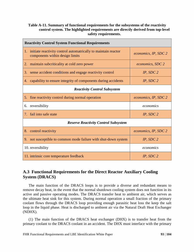
FHR Functional Requirements and LBE Identification White Paper 93 | 104
Table A-11. Summary of functional requirements for the subsystems of the reactivity control system. The highlighted requirements are directly derived from top-level
safety requirements.
Reactivity Control System Functional Requirements
1. initiate reactivity control automatrically to maintain reactor components within design limits economics, IP, SDC 2
2. maintain subcriticality at cold zero power economics, SDC 2
3. sense accident conditions and engage reactivity control IP, SDC 2
4. capability to ensure integrity of components during accidents IP, SDC 2
Reactivity Control Subsystem
5. fine reactivity control during normal operation economics, IP, SDC 2
6. reversibility economics
7. fail into safe state IP, SDC 2
Reserve Reactivity Control Subsystem
8. control reactivity economics, IP, SDC 2
9. not susceptible to common mode failure with shut-down system IP, SDC 2
10. reversibility economics
11. intrinsic core temperature feedback IP, SDC 2
A.3 Functional Requirements for the Direct Reactor Auxiliary Cooling System (DRACS)
The main function of the DRACS loops is to provide a diverse and redundant means to remove decay heat, in the event that the normal shutdown cooling system does not function in its active and passive operating modes. The DRACS transfer heat to ambient air, which serves as the ultimate heat sink for this system. During normal operation a small fraction of the primary coolant flows through the DRACS loop providing enough parasitic heat loss the keep the salt loop in the liquid phase. Heat is discharged to ambient air via the Natural Draft Heat Exchanger (NDHX).
(1) The main function of the DRACS heat exchanger (DHX) is to transfer heat from the primary coolant to the DRACS coolant in an accident. The DHX must interface with the primary

FHR Functional Requirements and LBE Identification White Paper 94 | 104
coolant and upper core structures system. To ensure high reliability the DHX must be designed for monitoring and management of degradation (corrosion, fouling, creep and other mechanisms). To reduce the probability of freezing in the DRACS loop, the DHX must have sufficient heat transfer area to maintain a low log-mean temperature difference (LMTD) with the primary coolant, compared to the LMTD with ambient air in the NDHX.
(5) The function of the NDHX is to provide a high-reliability ultimate heat sink for decay heat removal.
Furthermore, the NDHX must interface with the environment. This entails controlling and monitoring the ingress of foreign objects and deposition of external dust as well as encouraging ambient air entrainment to temper high temperatures of discharged air.
(6) Finally, the NDHX air flow must be controllable actively and manually (in the case of an accident) so that parasitic heat loss can be controlled to prevent overcooling. The air inlet must be located at a sufficiently high elevation to be protected from external events and attack, and the cold airflow must provide cooling of the concrete structures that protect the DRACS chimneys from external missiles and events. The air inlet damper at the entrance to the NDHX must fail to the safe state, open, and have a quick response time (~10s of seconds). The minimum air flow through the NDHX must be sufficiently large to provide adequate cooling for concrete structures located around the NDHX. Access to manually manipulate the NDHX inlet dampers must be controlled by the plant physical security system to prevent unauthorized manipulation.
(2,4,7) To ensure high reliability and effectiveness during operation the DHX, DRACS piping and the NDHX must protect against flow blockage and over cooling in all conditions, including the effects of damage caused by design-basis external events. During normal operation the heat loss to the DRACS system should be controlled and minimized to prevent overcooling and to minimize unnecessary parasitic heat loss. The NDHX should be designed to recover its function if localized freezing occurs.
The key functional requirements of the subsystems comprising the Direct Reactor Auxiliary Cooling System (DRACS) are summarized in Table A-12.

FHR Functional Requirements and LBE Identification White Paper 95 | 104
Table A-12. Functional requirements for subsystems of the DRACS. The highlighted requirements are directly derived from top-level safety requirements.
DRACS Functional Requirements
DRACS Heat Exchanger and Diode
1. transfer decay heat from primary coolant to DRACS coolant IP, SDC 3, 5
2. maintain low LMTD to prevent freezing SDC 3
DRACS Piping and Insulation/Electrical Heating
3. transfer heat from primary loop to ultimate heat sink during an accident SDC 3, 6
4. prevent overcooling and freezing, recover from localized freezing SDC 3
Natural Decay Heat Exchanger
5. use ambient air as the ultimate heat sink for decay heat removal SDC 3
6. control air flow to prevent overcooling SDC 3
7. minimize heat loss under normal operating conditions economics
A.4 Functional Requirements for Reactor Vessel and Reactor Cavity
(1) The primary function of the reactor vessel (RV) subsystem, and guard vessel (GV) subsystem (if used) is to contain the primary coolant salt in the primary integral loop.
(2) The RV must also transfer gravity and seismic loads to the building.
(4) The function of the reactor cavity cooling subsystem is to maintain the reactor cavity concrete structures within their temperature design limits.
(3,5) The function of the reactor cavity insulation system is to minimize heat losses from the reactor to prevent parasitic heat loss.
(6) The function of the electrical heating subsystem is to maintain the coolant salt in the liquid phase.
A buffer salt subsystem can be implemented to (7) add additional salt to the core if the RPV fails and (8) to reduce the stress on the RV by adding hydrostatic force on the outside to counter hydrostatic force on the inside. However, the buffer salt must not corrode the RV (9).
The concrete walls and liner subsystem must (10) provide a low-leakage containment boundary in DBEs and BDBEs and (11) shield workers from radiation. It must form an

FHR Functional Requirements and LBE Identification White Paper 96 | 104
impermeable boundary for leaked salt. Some types of concrete contain constituents that form a CO2 gas when heated beyond its design limits, creating a release mechanism for radionuclides – therefore, it is important that the composition of the concrete must be selected to prevent this release mechanism.
The concrete walls and liner system also provides the primary heat sink for decay heat removal under BDBE conditions (12). This system should be designed to provide significant thermal inertia, and to allow the connection of external portable equipment to provide heat removal during BDBE’s (e.g., to inject water to provide evaporative cooling for water-cooled cavity liners).
A key component to providing the functionality of the reactor cavity system can be accomplished by maintaining the structural integrity of this system’s components. Therefore, the RV, GV, and concrete walls subsystem must maintain their integrity by enduring mechanical and thermal stresses, accommodating thermal expansion, surviving seismic motion, etc. Furthermore, methods to monitor for potential degradation mechanisms for these systems should be provided to ensure their integrity.
The functional requirements for the key subsystems comprising the reactor cavity system are summarized in Table A-13.

FHR Functional Requirements and LBE Identification White Paper 97 | 104
Table A-13. Functional requirements for the subsystems of the reactor cavity system. The highlighted requirements are directly derived from top-level safety requirements.
Reactor Cavity System
Reactor Vessel/Guard Vessel Subsystem
1. contain primary coolant in primary integral loop economics, IP, SDC 5
2. transfer structural loads from reactor to building Economics, SDC 5
3. minimize heat losses from the reactor economics
Reactor Cavity Cooling/Insulation Subsystem
4. maintain concrete structures within their design limits economics, IP, SDC 6
5. minimize heat losses from the reactor economics
Electrical Heating Subsystem
6. maintain salt in liquid phase economics, IP, SDC 5
Buffer Salt Subsystem (If Used)
7. provide excess salt IP, SDC 3, 5
8. reduce stress on reactor pressure vessel IP SDC 3, 5
9. interface with reactor pressure vessel IP SDC 3, 5
Concrete Walls Subsystem
10. low-leakage containment boundary IP, SDC 1, 4, 6
11. radiation shielding economics
12. reliable heat sink for decay heat during BDBEs SDC 3
A.5 Functional Requirements for the Intermediate Loop
The intermediate loop system is comprised of the intermediate heat exchanger (IHX) subsystem, the power conversion heat exchanger (PCHX) or the process heat exchanger (PHX) subsystem, the shut-down cooling subsystem and the pumps, piping and drain tank subsystems.

FHR Functional Requirements and LBE Identification White Paper 98 | 104
(1) The main function of the IHX is to transfer heat from the primary coolant to the intermediate coolant. This function must be performed under normal full-power operation, AOOs (like start-up and shut-down) and DBEs.
An FHR will need a PCHX and/or PHX depending on whether its mission is to produce electric energy, process heat or both simultaneously.
(3) The PCHX transfers the heat from the intermediate coolant to the working fluid of the power conversion system. Initial FHR concepts utilized Brayton cycles (open-air or closed-helium/supercritical CO2). Thus, the PCHX must interface with either air, water/steam, CO2 or helium under requisite temperatures and pressures. The PCHX also plays a role in controlling the transfer of tritium to the power conversion fluid (Zhao and Peterson 2007; Holcomb, Peretz, and Qualls 2011).
(5) The PHX transfers the heat from the intermediate coolant to the working fluid of the process heat system. The PHX must interface with the process heat working fluid under requisite temperatures and pressures depending on specific application. The PHX must minimize transport of tritium to the process fluids
(7) The normal shutdown cooling subsystems provide a heat sink for start-up and shutdown transients. (8) Furthermore, it provides a diverse and redundant heat sink for decay heat removal in accidents. (9) If the normal shutdown cooling subsystems are integrated with the intermediate heat transfer system, then the intermediate loop should employ multiple subloops (depending upon the number of IHX’s), so that individual loops can be isolated for maintenance while maintaining normal shutdown cooling on a different loop.
(10) The piping subsystem transports fluid and heat between the IHXs, PCHX/PHXs, and shutdown cooling subsystems. The piping must maintain the coolant in a fluid phase, adding heat if required, and be configured to generate natural circulation heat transfer when forced circulation is not present. (11) The drain tank subsystem must accommodate the intermediate salt during maintenance. Therefore it must interface with the intermediate coolant and maintain it in the liquid phase.
The IHX, PCHX, and PHX (collectively referred to as HXs) the shut-down cooling, piping, and drain tank subsystems must protect against blocked flow and over cooling and provide a capability to detect and recover from these events. Furthermore, to provide their functionality the HXs must maintain their structural integrity by managing thermal creep, preventing chemical attack, and managing stresses under normal operating conditions, AOOs and DBEs. These structural integrity functions must be ensured and maintained by accommodating monitoring and maintenance for degradation from corrosion, fouling, creep and other mechanisms. The HXs and the piping systems must drain into the drain tank for maintenance. The performance of these sub systems must be predictable.
(2,4,6,9,12) These systems must also be designed to minimize costs by minimizing the volume of material from which the HXs are fabricated, minimize the height of the HXs (mostly in the IHX to minimize stacking issues), minimize primary coolant inventory within the IHXs, and reduce the circulating power for fluid through the HXs.

FHR Functional Requirements and LBE Identification White Paper 99 | 104
The key functional requirements for the subsystems comprising the intermediate salt loop system are summarized in Table A-14.
Table A-14. Functional requirements for the Intermediate Salt Loop Subsystems. The highlighted requirements are directly derived from top-level safety requirements.
Intermediate Salt Loop Functional Requirements
Intermediate Heat Exchanger (IHX)
1. transfer heat from primary to intermediate coolant economics, IP, SDC 3
2. minimize costs economics
Power Conversion Heat Exchanger (PCHX)
3. transfer heat from intermediate coolant to the power conversion system
economics, IP, SDC 3
4. minimize costs economics
Process Heat Exchanger (PHX)
5. transfer heat from intermediate coolant to the heat application economics, IP, SDC 3
6. minimize costs economics
Shutdown Cooling Subsystem
7. provide heat sink for start-up and shut-down transients economics, IP, SDC 3
8. provide diverse and redundant heat sink for decay heat removal IP, SDC 3
9. if integrated with intermediate loop, have redundancy to allow intermediate loop maintenance while maintaining cooling
Economics, IP, SDC 3
Piping and Drain Tank Subsystem
10. transport fluid between IHX, PCHX, PHX, and S/D cooling systems
economics, IP, SDC 3
11. drain tank must accommodate intermediate salt inventory economics, IP
12. minimize costs economics

FHR Functional Requirements and LBE Identification White Paper 100 | 104
A.6 Functional Requirements for the Main Support Systems
This main support system’s functional requirements definition considers the coolant chemistry, particulate and inventory control system (CCPIC), the cover gas chemistry, particulate and inventory control system (CGCPIC), the fuel handling system and plant control and instrumentation system (I&C). Functional requirements for addition support systems will be defined in functional requirements analysis for specific FHR designs.
The CCPIC (1) controls and (2) monitors the chemistry of each coolant loop (primary, intermediate, and DRACS) to prevent corrosion, (3) removes particulates in each coolant loop, (4) maintains the inventory of the coolant within the design limits, and (5) provides a capability to inject additional coolant into the reactor primary system and reactor cavity during BDBEs. Monitoring the concentration of 6Li might be part of the design basis requirements for FHRs because this concentration significantly affects the coolant void reactivity feedback of the FHR system.
The CGCPIC system (6) controls and (7) monitors the chemistry of the cover gas, (8) removes particulates from the cover gas and (9) maintains the pressure of the cover gas with design limits. Monitoring the chemical composition of the cover gas is an integral part of tritium management in FHRs. Furthermore, detecting fission products in the cover gas can inform the operator about unexpected fuel failures in the reactor. The control logic of this system should be developed to minimize radionuclide releases during accident scenarios.
(12) The fuel handling and storage system must maintain the fuel with design limits (especially temperature) to ensure the integrity of the fuel elements and thereby control radionuclides. Therefore, the fuel must be maintained in a subcritical state in fresh fuel storage as well as spent fuel storage. In spent fuel storage the decay heat must be removed and chemical attack prevented.
(13) The fuel handling system must implement a materials accountability program for economics, physical security, and IAEA safeguards.
A subsystem of the fuel handling system, the fuel loading and unloading (FLU) system manages the fuel elements in an FHR. The FLU system must (10) add fuel to and (11) remove fuel from the reactor core. This functionality entails interfacing with fuel elements, moving the fuel elements either mechanically or hydrodynamically, removing primary coolant from fuel element surface during discharge and recirculation, maintaining the fuel elements within their design limits (especially for temperature and chemical attack), maintaining strict materials accounting for nuclear safeguards, maintaining subcriticality outside the reactor, tolerating radiation emitted from fuel elements and preventing chemical attack from the primary coolant. Additionally, the fuel handling system should be designed to remove fuel even after DBEs and BDBEs.
The FLU in the pebble bed FHR variants must inject pebbles into corresponding pebble regions (cross-sectional region or pebble channel), sense and manage pebble fuel by pebble type (LEU, LWR-TRU, thorium, or inert graphite) and burnup or radiation dose. Furthermore, the FLU system must handle fractured pebble fragments, maintain the pebble bed fully packed in

FHR Functional Requirements and LBE Identification White Paper 101 | 104
systems with cross-sectional heterogeneity (to maintain structured bed geometry), and recirculate the pebbles.
The FLU in the fixed fuel FHR variant must shuffle fuel elements ensuring specific fuel elements are inserted into and removed from the correct lattice site.
A subsystem of the plant control system, the power control subsystem (PCS) must support (12) start up, (13) shut down, and (14) load following. The detailed design of the PCS depends upon the type of power conversion or process heat load coupled to an FHR.
The key functional requirements for the main support systems are summarized in Table A-15.

FHR Functional Requirements and LBE Identification White Paper 102 | 104
Table A-15. Functional requirements for Main Support Systems. The highlighted requirements are directly derived from top-level safety requirements.
Main Support Systems Functional Requirements
Coolant Chemistry, Particulates, and Inventory Control
1. maintain chemical composition of coolant within design limits Economics, IP, SDC 4,5
2. monitor chemical and isotopic composition of the coolant IP, SDC 2
3. manage particulates in coolant economics
4. manage coolant inventory SDC 4
5. inject additional coolant during BDBEs SDC4
Cover Gas Chemistry, Particulates, and Inventory Control
6. maintain cover gas composition within design limits economics, IP
7. monitor chemical composition of the cover gas IP
8. manage particulates in cover gas including activation products IP, SDC 1
9. manage pressure of cover gas including the release of tritium IP, SDC 1
Fuel Handling and Storage System
10. insert fuel elements into the reactor core economics, SDC 1
11. remove fuel elements from the reactor core economics, IP, SDC 1
12. maintain fuel within design limits economics, IP, SDC 1
13. maintain materials accountability economics, SG, NP
Plant Instrumentation and Control System/Power Control (PCS) Subsystem
14. Start-up economics, SDC 2
15. Shut-down economics, SDC 2
16. Load following (if practiced) economics, SDC 2
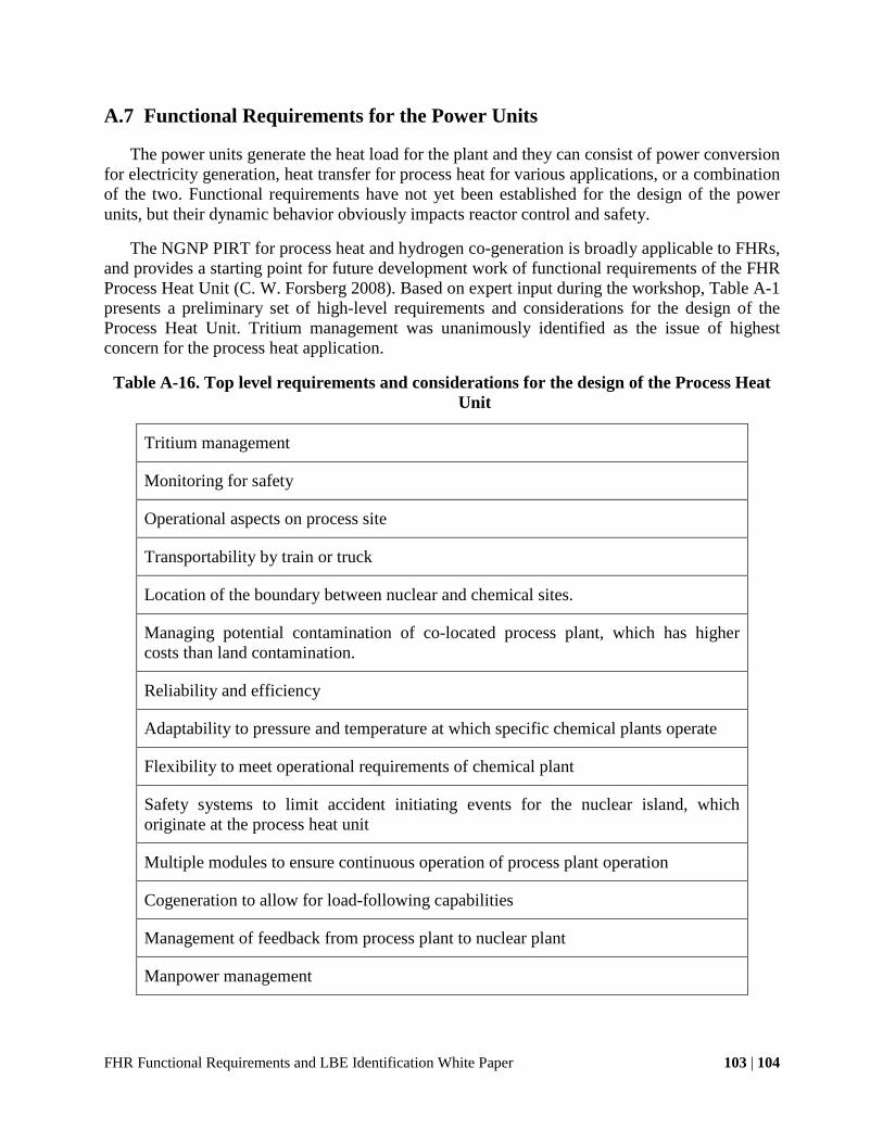
FHR Functional Requirements and LBE Identification White Paper 103 | 104
A.7 Functional Requirements for the Power Units
The power units generate the heat load for the plant and they can consist of power conversion for electricity generation, heat transfer for process heat for various applications, or a combination of the two. Functional requirements have not yet been established for the design of the power units, but their dynamic behavior obviously impacts reactor control and safety.
The NGNP PIRT for process heat and hydrogen co-generation is broadly applicable to FHRs, and provides a starting point for future development work of functional requirements of the FHR Process Heat Unit (C. W. Forsberg 2008). Based on expert input during the workshop, Table A-1 presents a preliminary set of high-level requirements and considerations for the design of the Process Heat Unit. Tritium management was unanimously identified as the issue of highest concern for the process heat application.
Table A-16. Top level requirements and considerations for the design of the Process Heat Unit
Tritium management
Monitoring for safety
Operational aspects on process site
Transportability by train or truck
Location of the boundary between nuclear and chemical sites.
Managing potential contamination of co-located process plant, which has higher costs than land contamination.
Reliability and efficiency
Adaptability to pressure and temperature at which specific chemical plants operate
Flexibility to meet operational requirements of chemical plant
Safety systems to limit accident initiating events for the nuclear island, which originate at the process heat unit
Multiple modules to ensure continuous operation of process plant operation
Cogeneration to allow for load-following capabilities
Management of feedback from process plant to nuclear plant
Manpower management

FHR Functional Requirements and LBE Identification White Paper 104 | 104
A.8 Functional Requirements for the Balance of Plant
This balance of plant’s functional requirements definition considers the reactor citadel, seismic base isolation and external event shield.
The reactor citadel (3) maintains the primary system’s geometry and it (4) serves as a filtered confinement under accident scenarios. (4) Under normal operation the reactor citadel ventilation system controls and monitors the transport of beryllium and radioactive aerosols to protect worker safety.
(5) The seismic base isolation protects the reactor and power unit builds from seismic loads.
(6) Finally, the external event shield protects the reactor from external initiating events such as severe weather and airplane crashes.
Some of the balance of plant systems, and their key functional requirements area listed in Table A-17.
Table A-17. Key systems and functional requirements for the Balance of Plant Area. Highlighted requirements are directly derived from top-level safety requirements.
Balance of Plant Functional Requirements
Reactor Citadel
1. geometry maintained under severe events SDC 6
2. filtered confinement ventilation system controls and monitors worker exposure to beryllium and radioactive aerosols
SDC 1
Seismic Base Isolation
3. protect reactor and power unit building from seismic loads SDC 6
External Event Shield
4. protect reactor building external accident initiators SDC 6
The requirements presented in this chapter are not an exhaustive list of FHR functional requirements. They focus on key functionality that is necessary for meeting the SDC with a defense-in-depth approach. The process of functional requirement identification is iterative with the licensing basis events (LBEs) identification, which is discussed in Chapter 4.