Embed Size (px)
Citation preview

1926 IEEE TRANSACTIONS ON COMMUNICATIONS, VOL. 50, NO. 12, DECEMBER 2002
Outdoor MIMO Wireless Channels: Modelsand Performance Prediction
David Gesbert, Member, IEEE, Helmut Bölcskei, Member, IEEE, Dhananjay A. Gore, andArogyaswami J. Paulraj, Fellow, IEEE
Abstract—We present a newmodel for multiple-input–multiple-output (MIMO) outdoor wireless fading channels and their ca-pacity performance. The proposed model is more general and real-istic than the usual independent and identically distributed (i.i.d.)model, and allows us to investigate the behavior of channel ca-pacity as a function of the scattering radii at transmitter and re-ceiver, distance between the transmit and receive arrays, and an-tenna beamwidths and spacing. We show how MIMO capacity isgoverned by spatial fading correlation and the condition numberof the channel matrix through specific sets of propagation parame-ters. The proposed model explains the existence of “pinhole” chan-nels which exhibit low spatial fading correlation at both ends of thelink but still have poor rank properties, and hence, low ergodic ca-pacity. In fact, the model suggests the existence of a more generalfamily of channels spanning continuously from full rank i.i.d. tolow-rank pinhole cases. We suggest guidelines for predicting highrank (and hence, high ergodic capacity) in MIMO channels, andshow that even at long ranges, high channel rank can easily be sus-tained under mild scattering conditions. Finally, we validate ourresults by simulations using ray tracing techniques. Connectionswith basic antenna theory are made.
Index Terms—Antenna arrays, channel capacity, channelmodeling, diversity, multiple-input–multiple-output channels,smart antennas, space–time coding, spatial multiplexing.
I. INTRODUCTION
THE PROSPECT of extraordinary improvements in the ca-pacity of wireless networks has drawn considerable at-
tention to multiple-input–multiple-output (MIMO) communi-cation techniques. MIMO methods make use of multi-elementantenna arrays at both the transmit and the receive side of aradio link to drastically improve the capacity over more tradi-tional single-input–multiple-output (SIMO) systems (with mul-tiple antennas typically being used at the base station only) [1],[5], [8], [27]. SIMO channels can provide diversity gain, array
Paper approved byM. Z.Win, the Editor for Equalization and Diversity of theIEEE Communications Society. Manuscript received August 30, 2000; revisedMarch 27, 2002. The work of H. Bölcskei was supported in part by the AustrianNational Science Foundation (FWF) under Grant J1868-TEC. This paper waspresented in part at IEEE Globecom 2000, San Francisco, CA, November 2000,and at the Asilomar Conference on Signals, Systems, and Computers, PacificGrove, CA, October 2000.D. Gesbert is with the Department of Informatics, University of Oslo, 0316
Oslo, Norway (e-mail: [email protected]).H. Bölcskei is with the Communication Technology Laboratory, Swiss
Federal Institute of Technology (ETH) Zurich, CH-8092 Zürich, Switzerland(e-mail: [email protected]).D. A. Gore and A. J. Paulraj are with the Information Systems Laboratory,
Department of Electrical Engineering, Stanford University, Stanford, CA94305-9510 USA (e-mail: [email protected]; [email protected]).Digital Object Identifier 10.1109/TCOMM.2002.806555
gain, and interference canceling gain. In addition to these ad-vantages,MIMO links can offer a so-calledmultiplexing gain byopening parallel spatial data pipes or channels within the samefrequency band at no additional power expenditure. In the pres-ence of rich multipath leading to antenna decorrelation and fullchannel rank, MIMO links offer capacity gains that are propor-tional to the minimum of the number of transmit and receiveantennas [10]. These gains can be achieved using spatial multi-plexing algorithms (a.k.a. “BLAST”) [1], [2], [8], [9], [26], [27].In the presence of channel rank loss one resorts to more robustlower rate transmission techniques based on space–time codes[16], [17], [28].1) Previous Work and Open Problems: Although a pro-
found understanding of MIMO channels is crucial in selectingproper signaling strategies in MIMO wireless networks, theliterature on realistic MIMO channel models remains scarce.Measurements of outdoor MIMO channels have been reportedin [18]–[21] without always providing insights into the relationbetween the channel structure, the corresponding capacity, andthe propagation environment. For the line-of-sight (LOS) case,specific arrangements of antenna arrays at the transmitter andthe receiver maximizing the orthogonality between antennasignatures (and hence, the capacity) have been reported in[15]. A detailed treatment of array gain and capacity of MIMOchannels for the case where both the transmitter and the re-ceiver know the channel can be found in [7]. In the fading case,previous studies have mostly been confined to independent andidentically distributed (i.i.d.) Gaussian channels, an idealisticassumption where the entries of the channel matrix are modeledas independent complex Gaussian random variables (see, e.g.,[10]). The influence of spatial fading correlation at either thetransmit or the receive side of a wireless MIMO radio link hasbeen addressed in [22], [23], and [27]. While the models usedin [22] and [27], for example, are simple and allow us to gaininsight into the impact of propagation conditions on MIMOcapacity, they assume that only spatial fading correlation isresponsible for the rank structure of the MIMO channel. Inpractice, however, the realization of high MIMO capacity inactual radio channels is sensitive not only to the fading corre-lation, but also to the structure of scattering in the propagationenvironment. In the existing literature, high-rank behavior hasonly loosely been linked to the existence of a dense scatteringenvironment. Aforementioned results of measurements in urbansettings tend to corroborate this behavior. However, several keyquestions regarding outdoor MIMO channels remain open.• What is the capacity of a typical outdoor MIMO channel?• What are the key propagation parameters governing thecapacity behavior?
0090-6778/02$17.00 © 2002 IEEE
Authorized licensed use limited to: ETH BIBLIOTHEK ZURICH. Downloaded on February 10, 2010 at 06:10 from IEEE Xplore. Restrictions apply.
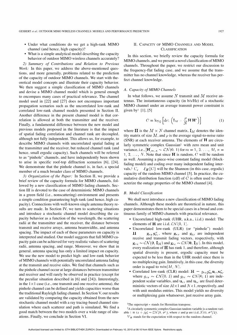
GESBERT et al.: OUTDOOR MIMO WIRELESS CHANNELS: MODELS AND PERFORMANCE PREDICTION 1927
• Under what conditions do we get a high-rank MIMOchannel (and hence, high capacity)?
• What is a simple analytical model describing the capacitybehavior of outdoor MIMO wireless channels accurately?
2) Summary of Contributions and Relation to PreviousWork: In this paper, we address the above-mentioned ques-tions, and more generally, problems related to the predictionof the capacity of outdoor MIMO channels. We start with the-oretical model concepts and illustrate their capacity behavior.We then suggest a simple classification of MIMO channelsand devise a MIMO channel model which is general enoughto encompass many cases of practical relevance. The channelmodel used in [22] and [27] does not encompass importantpropagation scenarios such as the uncorrelated low-rank andcorrelated low-rank channel models presented in Section II.Another difference in the present channel model is that cor-relation is allowed at both the transmitter and the receiver.Finally, a fundamental difference between the new model andprevious models proposed in the literature is that the impactof spatial fading correlation and channel rank are decoupled,although not fully independent. This allows us, for example, todescribe MIMO channels with uncorrelated spatial fading atthe transmitter and the receiver, but reduced channel rank (andhence, small ergodic capacity). Such channels will be referredto as “pinhole” channels, and have independently been shownto arise in specific roof-top diffraction scenarios [6], [24].We demonstrate that the pinhole channel is, in fact, a specialmember of a much broader class of MIMO channels.3) Organization of the Paper: In Section II, we provide a
brief review of the capacity formula for MIMO channels, fol-lowed by a new classification of MIMO fading channels. Sec-tion III is devoted to the case of deterministic MIMO channelsin a green field (i.e., nonscattering) environment and presentsa simple condition guaranteeing high rank (and hence, high ca-pacity). Connections with well-known single antenna theory re-sults are made. In Section IV, we turn to scattering situationsand introduce a stochastic channel model describing the ca-pacity behavior as a function of the wavelength, the scatteringradii at the transmitter and the receiver, the distance betweentransmit and receive arrays, antenna beamwidths, and antennaspacing. The impact of each of these parameters on capacity isinterpreted and studied. Our model suggests that full MIMO ca-pacity gain can be achieved for very realistic values of scatteringradii, antenna spacing, and range. Moreover, we show that ingeneral, antenna spacing has only a limited impact on capacity.We use the new model to predict high- and low-rank behaviorofMIMO channels with potentially uncorrelated antenna fadingat the transmit and receive sides. We find that channels such asthe pinhole channel occur at large distances between transmitterand receiver and will rarely be observed in practice (except forthe peculiar situation described in [6] and [24]). Interestingly,in the 1 1 case (i.e., one transmit and one receive antenna), thepinhole channel can be defined and yields capacities worse thanthe traditional Rayleigh fading channel. In Section V, our resultsare validated by comparing the capacity obtained from the newstochastic channel model with a ray tracing-based channel sim-ulation where each scatterer and path is simulated. We find agood match between the two models over a wide range of situ-ations. Finally, we conclude in Section VI.
II. CAPACITY OF MIMO CHANNELS AND MODELCLASSIFICATION
In this section, we briefly review the capacity formula forMIMOchannels, andwe present a novel classification ofMIMOchannels. Throughout the paper, we restrict our discussion tothe frequency-flat fading case, and we assume that the trans-mitter has no channel knowledge, whereas the receiver has per-fect channel knowledge.
A. Capacity of MIMO ChannelsIn what follows, we assume transmit and receive an-
tennas. The instantaneous capacity (in b/s/Hz) of a stochasticMIMO channel under an average transmit power constraint isgiven by1 [1], [5]
(1)
where is the channel matrix, denotes the iden-tity matrix of size , and is the average signal-to-noise ratio(SNR) at each receiver antenna. The elements of are circu-larly symmetric complex Gaussian2 with zero mean and unitvariance, i.e., for
. Note that since is random, will be randomas well. Assuming a piece-wise constant fading model (block-fading model) and coding over many independent fading inter-vals,3 will be the Shannon (in this case, ergodic)capacity of the random MIMO channel [5]. In practice, the cu-mulative distribution function (cdf) of is often used to char-acterize the outage properties of the MIMO channel [4].
B. Model ClassificationWe shall next introduce a new classification of MIMO fading
channels. Although these models are theoretical in nature, thispaper demonstrates them to be special cases in a broad and con-tinuous family of MIMO channels with practical relevance.• Uncorrelated high-rank (UHR, a.k.a., i.i.d.) model: Theelements of are i.i.d. .
• Uncorrelated low-rank (ULR) (or “pinhole”) model:, where and are independent
receive and transmit fading vectors, respectively, withand . In this model,
every realization of has rank 1, and therefore, althoughspatial diversity is present, ergodic capacity must beexpected to be less than in the UHR model since there isno multiplexing gain. Intuitively, in this case, the diversityorder is equal to .
• Correlated low-rank (CLR) model:where and are inde-pendent scalar variables, and and are fixed deter-ministic vectors of size 1 and 1, respectively, andwith unit modulus entries. This model yields no diversityor multiplexing gain whatsoever, just receive array gain.
1The superscript stands for Hermitian transpose.2A circularly symmetric complex Gaussian random variable is a random vari-
able , where and are i.i.d. .3 stands for the expectation with respect to the random channel.
Authorized licensed use limited to: ETH BIBLIOTHEK ZURICH. Downloaded on February 10, 2010 at 06:10 from IEEE Xplore. Restrictions apply.

1928 IEEE TRANSACTIONS ON COMMUNICATIONS, VOL. 50, NO. 12, DECEMBER 2002
Fig. 1. ULR model shows the impact of rank loss on capacity. CLR channelloses both multiplexing and diversity gains.
Fig. 2. Capacity curves for the 1 1 HR (Rayleigh) and 1 1 LR (doubleRayleigh) channels. The double Rayleigh channel has worsened fadingstatistics.
We also define the following single-antenna models to whichwe extend the “low rank” (LR) and “high rank” (HR) concepts:• 1 1 HR, defined by the UHR model with ,also known as Rayleigh fading channel.
• 1 1 LR, defined by the ULR or CLR model with(double Rayleigh channel).
Note that the low-rank models (ULR, CLR, 1 1 LR) abovedo not use the traditional normal distribution for the entries of, but instead the product of two Gaussian variables. This type
of distribution will be shown later to occur in important practicalsituations.The above models exhibit very different capacity behavior.
The cdf of the corresponding capacities is depicted in Figs. 1and 2 for dB. Fig. 1 clearly shows the impact of rankloss on capacity. The loss in the 3 3 ULR case is due to the factthat there is only one spatial data pipe. However, in this case,much of the diversity gain is preserved because the antennasstill fade in an uncorrelated fashion. Antenna correlation causes
Fig. 3. -input -output MIMO green field model.
additional loss in capacity, which can be seen from the cdf of the3 3 CLR channel in Fig. 1. From Fig. 2, we can conclude thatthe 1 1 LR model (double Rayleigh) yields less capacity thanthe 1 1 HR model (Rayleigh) for a wide range of outage rates.This is due to the intuitive fact that a double Rayleigh channelwill fade twice as often as a standard Rayleigh channel.
III. GREEN FIELD MIMO CHANNELS
In this section, we derive conditions guaranteeing an HRMIMO channel in a green field (or LOS) environment. Con-centrating on the ideal nonscattering nonfading case (i.e.,deterministic channels), we suggest that rank properties aregoverned by simple geometrical propagation parameters. Theresults below are applicable in flat/rural wireless deployments.We shall see later in the paper that our findings suggestguidelines for the fading case as well.Considering the transmitter, receiver setup de-
scribed in Fig. 3, we assume bore-sight propagation fromthe transmit array to the receive array. In addition, we as-sume the signal radiated by the th transmit antenna toimpinge as a plane wave on the receive array at an angle of. This assumption is justified when the antenna aperture
is much smaller than the range . Finally, using the sameassumption, the effect of path loss can be ignored. Denotingthe signature vector induced by the th transmit antenna as
, whereis the wavelength, and and are the transmit and receive
antenna spacing, respectively, we have .The common phase shift due to the distance betweentransmitter and receiver has no impact on capacity and is,therefore, ignored. Clearly, when the ( )(all other parameters being fixed) approach zero we find thatapproaches the all-ones matrix, and therefore, has rank
1. In practice, this happens for large range . As the rangedecreases, linear independence between the signatures starts tobuild up. We choose to use the full orthogonality between thesignatures of adjacent pairs of transmit antennas as a criterionfor the receiver to be able to separate the transmit signatureswell, implying high capacity. This condition reads
(2)
For practical values of , , and , orthogonality will occurfor small . We can, therefore, set
. Consequently, condition (3) can be rewritten as
(3)
Authorized licensed use limited to: ETH BIBLIOTHEK ZURICH. Downloaded on February 10, 2010 at 06:10 from IEEE Xplore. Restrictions apply.

GESBERT et al.: OUTDOOR MIMO WIRELESS CHANNELS: MODELS AND PERFORMANCE PREDICTION 1929
which implies
(4)
Note that this is not sufficient to achieve exact orthogonality,although for a large number of receive antennas it will tend tobe sufficient. In practice, for larger values of antenna spacing[larger than that imposed by (4)], the transmit antennas can fallinto the grating lobes of the receive array, in which case, orthog-onality is not realized. Interestingly, (4) can be rewritten into
(5)
which can be reinterpreted in terms of basic antenna theory asfollows [25]. The angular resolution of the receive array (in-versely proportional to the aperture in wavelengths) should beless than the angular separation between two neighboring trans-mitters. Of course, a similar condition in terms of transmit res-olution can be obtained by enforcing orthogonality between therows of .In a pure LOS situation, orthogonality can only be achieved
for very small values of range . For example, at a frequency of2 GHz with , a maximum of m is acceptable for1 m antenna spacing. Note that the orthogonality condition (4)depends on the number of receive antennas only. This is so,sincewe are seeking separability of only the two closest transmitantennas. Clearly, linear independence of adjacent transmit an-tenna signatures is a necessary (but not sufficient) condition forthe global channel matrix to have full rank. We show laterin the paper how the guideline (4) extends nicely to scatteringscenarios.
IV. DISTRIBUTED SCATTERING MIMO MODEL
We now turn to the case of non-line-of-sight (NLOS) chan-nels, where fading is induced by the presence of scatterers. Thepurposes of this section are the following:• to develop a stochasticMIMOchannelmodel that capturesseparately the diversity and rank properties as suggestedby Figs. 1 and 2;
• to suggest how the guideline offered by (4) for LOS chan-nels can be extended to fading channels upon appropriateredefinition of and .
In the following, for the sake of simplicity, we consider the ef-fect of near-field scatterers only, i.e., scatterers which are eitherin the vicinity (typically a few tens to hundreds of meters away)of the transmitter or the receiver. We ignore remote scatterers,assuming that the path loss will tend to limit their contribution tothe overall channel. In addition, because local scatterers intro-duce multipath length differences which are small compared tothe transmit–receive range, we assume that the quasi-commonpath attenuation can be factored out of the channel and focuson microscopic (Rayleigh) fading only. We also limit this par-ticular study to a frequency-flat fading channel. The benefit ofmultipath delay spread in terms of increasing the rank richnessof the channel was demonstrated in [3] and [27].
Fig. 4. Propagation scenario for SIMO fading correlation. Each scatterertransmits a plane-wave signal to a linear array.
A. SIMO Fading Correlation ModelWe consider a linear receive array of omnidirectional an-
tennas with spacing . A number of distributed scatterers infront of the array act as ideal reflectors (i.e., perfect omnidirec-tional scatterers) of a signal which eventually impinges on thereceive array. The plane-wave directions of arrival (DOAs) ofthese signals span an angular spread of radians (see Fig. 4).Several distributions can be considered for the DOAs, includinguniform, Gaussian, Laplacian, etc. [12]–[14]. The addition ofdifferent plane-waves causes space-selective fading at the re-ceive antennas. It is well known that the resulting fading corre-lation is governed by the angle spread, the antenna spacing, andthe wavelength. The receive array response vector can conse-quently be modeled as
or equivalently with(6)
where is the receive correlation matrix.Different assumptions on the statistics of the DOAs will yielddifferent expressions for [12]–[14]. For uniformlydistributed DOAs, we find [12], [14]
(7)where (odd) is the number of scatterers with correspondingDOAs . For “large” values of angle spread and/or antennaspacing , will converge to the identity matrix, whichgives uncorrelated fading. For “small” values of , the cor-relation matrix becomes rank deficient (eventually rank one),causing (fully) correlated fading. For the sake of simplicity, wefurthermore assume the mean DOA to be orthogonal to the array(bore sight). Some comments on this model are now in order.• Impact of Directional Antennas: If directional antennasare used instead of omnidirectional antennas, the effec-tive angle spread perceived by the array can be obtainedby intersecting the scattering angle spread with the mainlobes of the antennas. In what follows, the directionality of
Authorized licensed use limited to: ETH BIBLIOTHEK ZURICH. Downloaded on February 10, 2010 at 06:10 from IEEE Xplore. Restrictions apply.

1930 IEEE TRANSACTIONS ON COMMUNICATIONS, VOL. 50, NO. 12, DECEMBER 2002
Fig. 5. Propagation scenario for fading MIMO channel. We assume plane-wave propagation. Scatterers are ideal reflectors.
antennas is accounted for by selecting the effective anglespread properly.
• Spatial Fading Correlation at the Transmitter: Themodel provided in (6) can readily be applied to an arrayof transmit antennas with corresponding antenna spacingand signal departure angle spread.
B. MIMO Correlated Fading Model
We now turn to the NLOS MIMO case by considering thepropagation scenario depicted in Fig. 5. The propagation pathbetween the two arrays is obstructed on both sides of the linkby a set of significant near-field scatterers (such as buildingsand large objects) referred to as transmit or receive scatterers.Scatterers are modeled as omnidirectional ideal reflectors. Theextent of the scatterers from the horizontal axis is denoted asand , respectively. When omnidirectional antennas are used,
and correspond to the transmit and receive scatteringradius, respectively. On the receive side, the signal reflected bythe scatterers onto the antennas impinge on the array with an an-gular spread denoted by , where is a function of the distancebetween the array and the scatterers. Similarly, on the transmitside we define an angular spread . In general, using directionalantennas instead of omnidirectional antennas will tend to de-crease the effective values of and and hence, the angularspreads. The scatterers are assumed to be located sufficientlyfar from the antennas for the plane-wave assumption to hold.We furthermore assume that and (local scat-tering condition).1) Signal at the Receive Scatterers: We assume scatterers
on both sides, where is an arbitrary, large enough numberfor random fading to occur (typically 10 is sufficient).The exact locations of the scatterers are irrelevant here. Everytransmit scatterer captures the radio signal and reradiates it inthe form of a plane wave toward the receive scatterers, which areviewed as an array of virtual antennas with average spacing2 , and as such, experience an angle spread defined by
. We denote the vector signal originatingfrom the th transmit antenna and captured by the receivescatterers as . Approximating the
receive scatterers as a uniform array of sensors and using thecorrelation model of (6), we find
or equivalently
with(8)
For uncorrelated transmit antennas, the matrix describingthe propagation between the transmit antennas and the re-ceive scatterers simply writes
(9)
where is an i.i.d. Rayleighfading matrix. However, there is generally correlation betweenthe transmit antennas because of finite angle spread and insuf-ficient antenna spacing. Therefore, a more appropriate modelbecomes
(10)
where is the matrix controlling the transmit an-tenna correlation as suggested in the transmit form of (6).2) MIMO Model: Like the transmit scatterers, the receiver
scatterers are assumed to ideally reradiate the captured energy.As shown in Fig. 5, a set of plane waves, with total angle spread, impinge on the receive array. Denoting the distance between
the th scatterer and the th receive antenna as , the vectorof received signals from the th transmit antenna can be writtenas
...... (11)
Collecting all receive and transmit antennas according to, we obtain the following MIMO channel model:
(12)
Authorized licensed use limited to: ETH BIBLIOTHEK ZURICH. Downloaded on February 10, 2010 at 06:10 from IEEE Xplore. Restrictions apply.

GESBERT et al.: OUTDOOR MIMO WIRELESS CHANNELS: MODELS AND PERFORMANCE PREDICTION 1931
Fig. 6. Example of pinhole realization. Reflections around the base transmitterstations and subscribers cause locally uncorrelated fading. However, because thescatter rings are too small compared to the separation between the two rings, thechannel rank is low.
The problemwith the expression in (12) is the explicit use of de-terministic phase shifts in the matrix which makes the modelinconvenient. The simple equivalence result below allows us toget rid of this inconvenience and obtain a fully stochastic, hencesimpler, MIMO channel model.Lemma: For , has the same pdf as
, where is an i.i.d. Rayleigh fading matrix ofsize .
Proof: See the Appendix.After proper power normalization4 and replacing by (10),
we obtain the following simple MIMO transfer function:
(13)
C. Interpretation and the Pinhole ChannelThe model suggested in (13) lends itself to several interesting
interpretations, explaining the effect of propagation parameterson the capacity behavior of MIMO channels.• Our model is symmetric in structure, which was to be ex-pected from the scenario considered.
• The spatial fading correlation between the transmit an-tennas, and therefore, the transmit diversity gain, is gov-erned by the deterministic matrix and hence, im-plicitly by the local transmit angle spread, the transmitantenna beamwidth and spacing. On the receive side, thefading correlation is similarly controlled by the receiveangle spread, antenna beamwidth, and antenna spacingthrough .
• Assume that fading is uncorrelated at both sides of thelink (i.e., and ). Equation(13) shows that it is nevertheless well possible to havea rank-deficient MIMO channel with reduced capacity.Such a channel is dubbed a pinhole channel because scat-tering (fading) energy travels through a very thin air pipe,preventing channel rank from building up. In practice, thisoccurs when the rank of drops caused by, e.g.,large transmit–receive range , or small , or , orboth. An example of a quasi-pinhole channel is illustratedin Fig. 6. This nicely extends the analysis carried out inthe green field case (4) and is confirmed by simulations in
4 is normalized such that the channel energy is independent of the numberof scatterers.
Section V. Note that and play a role analogous toand , respectively, in the green field case. Also, this ob-servation suggests that additional scatterers lying betweenthe transmit and receive array and not contributing to in-creased scattering angle spread will not contribute to ca-pacity. Conversely, potential remote scatterers with signif-icant impact on the total channel energy will increase theeffective value of and quickly help build up additionalcapacity.
• Equation (13) suggests how, in the scattering case, the rankbehavior of the MIMO channel is governed by the scat-tering radii and by the range, not by the physical antennaspacing. Scatterers can be viewed as virtual antenna ar-rays with very large spacing and aperture. Measurementsof scattering radii around 100 m in typical urban settingshave been reported in [13].The physical antenna spacing has limited impact on the
capacity, unless it is very small, rendering antennas corre-lated, or very large so that it impacts the scattering radiusitself. Antennas will remain close to uncorrelated with just
spacing for a reasonably high local angle spread/an-tenna beamwidth. Note that if scattering is absent at oneend of the link, the relevant parameter on that particularend driving the MIMO rank becomes the antenna spacing,which then must be greatly increased in order to achievehigh rank. Of course, onemay use dual-polarized antennasto remove the need for scatterers, because dual-polariza-tion tends to make the channel matrix orthogonal, but thislimits the system to a capacity doubling one at most.
• When either the transmit or the receive antennas are fullycorrelated due to small local angle spread, the rank of theMIMO channel also drops. In this situation, the diversityand multiplexing gains vanish, preserving only the receivearray gain. Note that there is no transmit array gain, sincewe assumed that the channel is unknown at the transmitter.
• From the above remarks, it follows that antenna corre-lation causes rank loss but the converse is not true. Ourmodel is, therefore, more general than previously reportedmodels.
• The new model contains the product of two randomRayleigh distributed matrices. This is in contrast withthe traditional Rayleigh MIMO model of [1] and [10].Depending on the rank of , the resultingMIMO fading statistics ranges “smoothly” from Gaussianto product of two independent Gaussians.— In the HR region, becomes an identitymatrix. Using the central limit theorem, the product
approaches a single Rayleigh distributedmatrix, which justifies the traditional model in thatparticular case.
— In the LR (i.e., rank one) region, isthe all-ones matrix. The MIMO channel becomes
, an outer product of two vec-tors with independent transmit and receive Rayleighfading vectors. In this case, we have no multiplexinggain, but there is still diversity gain with the exactamount depending on the transmit and receive fadingcorrelation.
Authorized licensed use limited to: ETH BIBLIOTHEK ZURICH. Downloaded on February 10, 2010 at 06:10 from IEEE Xplore. Restrictions apply.

1932 IEEE TRANSACTIONS ON COMMUNICATIONS, VOL. 50, NO. 12, DECEMBER 2002
Fig. 7. Capacity cdf obtained with MIMO model for three sets of parameters.From left to right. Set 1: m, km. Set 2:km, km. Set 3: m, km. The theoretical
ULR and UHR models are plotted for comparison (dotted lines).
— In practice, depending on local angle spread and an-tenna spacing, the model will range smoothly fromCLR to UHR.
— In the 1 1 case, meaningful HR and LR modelscan still be defined taking into account the rank of
. The HR model is the traditional Rayleighchannel. The LR model has “double Rayleigh” distri-bution with capacity behavior worse than Rayleigh aswas shown earlier.
— The model does not suggest the existence of a “corre-lated HR” MIMO channel, which corresponds to intu-ition.
V. NUMERICAL EVALUATION
In order to verify our new model, we use a comparison withan explicit ray-tracing model. In every simulation, 500 inde-pendent Monte-Carlo realizations of the ray-tracing channel aregenerated. The capacity distribution predicted by the proposedstochastic MIMOmodel for various values of the key model pa-rameters is compared to that achieved by the actual ray tracingmodel with the same parameters.The ray tracing model follows the scenario depicted in Fig. 5.
In all examples, we used transmit and receive scat-terers which are randomly distributed around a line perpendic-ular to the axis. However, we found that the final capacity re-sults are insensitive to the particular location of the scatterers, aslong as and the angular spreads remain fixed. We used
and placed the scatterers at a distance fromthe transmit array and from the receive array. For simplifi-cation, we use in all simulations in orderto maintain a high local angle spread and hence, low antennacorrelation. The frequency was set to 2 GHz and the SNR was10 dB. To introduce random fading, we use small5 random per-turbations of the transmit and receive antenna array positions in
5Small enough not to affect the values of the scattering radii.
Fig. 8. Capacity cdf obtained for the 1 1 model. We use two sets ofparameters from left to right. Set 1: m, km. Set 2:
m, km.
Fig. 9. Average (ergodic) capacity as a function of . The range isfixed to 10 km. Capacity builds up quickly as the scattering radius increases.
each of the Monte-Carlo experiments. The capacity distributionpredicted by our channel model for the corresponding set of pa-rameters is plotted alongside for comparison. This process wascarried out for three separate sets of control parameters, cov-ering the region between the UHR and the ULR models. Theresults are depicted in Fig. 7. Fig. 8 illustrates the impact of therank of on the capacity in the 1 1 case. The pro-posed channel model predicts the capacity distribution up to oneb/s/Hz in all cases, and becomes almost exact as we approachUHR and ULR regions.Finally, another validation is aimed at predicting the HR be-
havior of the channel using an extension of (4). Fig. 9 is a plot ofergodic (average) capacity for varying with fixedat 10 km. A possible generalized HR prediction formula is
(14)
Authorized licensed use limited to: ETH BIBLIOTHEK ZURICH. Downloaded on February 10, 2010 at 06:10 from IEEE Xplore. Restrictions apply.

GESBERT et al.: OUTDOOR MIMO WIRELESS CHANNELS: MODELS AND PERFORMANCE PREDICTION 1933
where can be interpreted as the maximum spacingachieved by virtual antennas distributed over the distance of
. These virtual antennas are obtained by mapping the phys-ical antennas onto the scatterers. Similar to (4), (14) can be rein-terpreted in terms of basic antenna theory as stating that the res-olution of one of the two virtual arrays must be less than theangle of separation between neighboring virtual antennas on theother side. This formula predicts the HR region to start around23 m of scattering radius, a little before but close to the knee inthe figure. The result shows how capacity builds up with scat-tering. It also suggests that the effective aperture of the “vir-tual antennas” is slightly less than what is predicted by . Itconfirms, though, that the high-capacity region is attained veryeasily, even for a very large range. This also provides an expla-nation why recent measurement campaigns in urban and sub-urban settings have not been able to spot pinhole channels sofar.
VI. CONCLUSION
We introduced a model for describing the capacity behaviorof outdoor MIMO channels. The new model describes theeffects of certain propagation geometry parameters in LOS andfading (NLOS) situations. Moreover, it allows the study of thebehavior of channel rank as a function of antenna spacing andrange in LOS situations, or more practically, as a function ofscattering radius and the range in fading situations. The modelpredicts excellent performance outdoors for very reasonablevalues of scattering radius, and exhibits small sensitivity ofMIMO channel rank to antenna spacing. We pointed out theexistence of pinhole channels for which antennas are perfectlydecorrelated at the transmitter and the receiver, and yet therank properties are poor and hence, capacity will decrease.This typically occurs for very large values of the range .Finally, we validated our stochastic channel model throughcomparisons with a ray tracing model.
APPENDIXPROOF OF THE LEMMA
Let be the eigen-decomposition of. According to (10) and (12)
(15)
Assuming that is large enough and the receive scatterer posi-tions are random (with all scatterer locations following the samedistribution, and the scatterer positions varying in an indepen-dent fashion from scatterer to scatterer), the central limit the-orem applied to yields . Thecorrelation between the rows of is governed by the receiveangle spread and the antenna spacing through [12].The columns of all have the same distribution. Furthermore,using the unitarity of , it follows that the columns of are un-correlated and hence, independent. We therefore have the equiv-alence in distribution
(16)
where is an i.i.d. Rayleigh distributed matrix.Hence, for large , we have .Finally, the distribution of is unchanged if weright-multiply by the unitary matrix , resulting in
.
ACKNOWLEDGMENT
The authors would like to thank Prof. J. Bach Andersen forhis helpful comments on an earlier version of this manuscript.
REFERENCES[1] G. J. Foschini, “Layered space–time architecture for wireless commu-
nication in a fading environment when using multi-element antennas,”Bell Labs Tech. J., pp. 41–59, Autumn 1996.
[2] A. J. Paulraj and T. Kailath, “Increasing capacity in wireless broad-cast systems using distributed transmission/directional reception,” U.S.Patent no. 5 345 599, 1994.
[3] R. Müller, “A random matrix model of communication via antenna ar-rays,” IEEE Trans. Inform. Theory, vol. 48, pp. 2495–2506, Sept. 2002.
[4] E. Biglieri, J. Proakis, and S. Shamai, “Fading channels: Information-theoretic and communications aspects,” IEEE Trans. Inform. Theory,vol. 44, pp. 2619–2692, Oct. 1998.
[5] I. E. Telatar, “Capacity of multiantenna Gaussian channels,” Eur. Trans.Telecommun., vol. 10, no. 6, pp. 585–595, Nov./Dec. 1999.
[6] D. Chizhik, G. J. Foschini, M. J. Gans, and R. A. Valenzuela, “Key-holes, correlations, and capacities of multielement transmit and receiveantennas,” IEEE Trans. Wireless Commun., vol. 1, pp. 361–368, Apr.2002.
[7] J. Bach Andersen, “Array gain and capacity for known random chan-nels with multiple element arrays at both ends,” IEEE J. Select. AreasCommun., vol. 18, pp. 2172–2178, Nov. 2000.
[8] G. G. Raleigh and J. M. Cioffi, “Spatio–temporal coding for wirelesscommunication,” IEEE Trans. Commun., vol. 46, pp. 357–366, Mar.1998.
[9] G. G. Raleigh and V. K. Jones, “Multivariate modulation and coding forwireless communication,” IEEE J. Select. Areas Commun., vol. 17, pp.851–866, May 1999.
[10] G. J. Foschini and M. J. Gans, “On limits of wireless communications ina fading environment when using multiple antennas,”Wireless PersonalCommun., vol. 6, pp. 311–335, 1998.
[11] “Experimental results of MIMO technology in an indoor-to-indoor en-vironment,” Gigabit Wireless Inc., Internal Tech. Rep., Mar. 1999.
[12] D. Asztély, “On antenna arrays in mobile communication systems:Fast fading and GSM base station receiver algorithms,” Royal Instituteof Technology, Stockholm, Sweden, Tech. Rep. IR-S3-SB-9611, Mar.1996.
[13] J. Fuhl, A. F. Molisch, and E. Bonek, “Unified channel model for mobileradio systems with smart antennas,” Proc. IEE Radar, Sonar Navig., vol.145, pp. 32–41, Feb. 1998.
[14] R. B. Ertel, P. Cardieri, K. W. Sowerby, T. S. Rappaport, and J. H. Reed,“Overview of spatial channel models for antenna array communicationsystems,” IEEE Pers. Commun. Mag., pp. 10–22, Feb. 1998.
[15] P. Driessen and G. J. Foschini, “On the capacity formula for multiple-input multiple-output wireless channels: A geometric interpretation,”IEEE Trans. Commun., vol. 47, pp. 173–176, Feb. 1999.
[16] J. Guey, M. Fitz, M. Bell, and W. Kuo, “Signal design for transmitterdiversity wireless communication systems over Rayleigh fading chan-nels,” in Proc. IEEE VTC, Atlanta, GA, 1996, pp. 136–140.
[17] V. Tarokh, N. Seshadri, and A. R. Calderbank, “Space–time codes forhigh data rate wireless communication: Performance criterion and codeconstruction,” IEEE Trans. Inform. Theory, vol. 44, pp. 744–765, Mar.1998.
[18] J. P. Kermoal, P. E. Mogensen, S. H. Jensen, J. B. Andersen, F. Fred-eriksen, T. B. Sorensen, and K. I. Pedersen, “Experimental investigationof multipath richness for multi-element transmit and receive antenna ar-rays,” in Proc. IEEE VTC Spring 2000, vol. 3, Tokyo, Japan, 2000, pp.2004–2008.
[19] C. C. Martin, J. H. Winters, and N. R. Sollenberger, “Multiple-inputmultiple-output (MIMO) radio channel measurements,” in Proc. IEEEVTC Fall 2000, vol. 2, Boston, MA, 2000, pp. 774–779.
[20] J. Ling, D. Chizhik, P. Wolniansky, R. Valenzuela, N. Costa, and K.Huber, “Multiple transmit multiple receive (MTMR) capacity survey inManhattan,” Electron. Lett., vol. 37, no. 16, pp. 1041–1042, Aug. 2001.
Authorized licensed use limited to: ETH BIBLIOTHEK ZURICH. Downloaded on February 10, 2010 at 06:10 from IEEE Xplore. Restrictions apply.

1934 IEEE TRANSACTIONS ON COMMUNICATIONS, VOL. 50, NO. 12, DECEMBER 2002
[21] P. Soma, D. S. Baum, V. Erceg, R. Krishnamoorthy, and A. J. Paulraj,“Analysis and modeling of multiple-input multiple-output (MIMO)radio channel based on outdoor measurements conducted at 2.5 GHzfor fixed BWA applications,” in Proc. IEEE Int. Conf. Communications(ICC), vol. 1, New York, NY, 2002, pp. 272–276.
[22] D. Shiu, G. J. Foschini, M. J. Gans, and J. M. Kahn, “Fading correlationand its effect on the capacity of multi-element antenna systems,” IEEETrans. Commun., vol. 48, pp. 502–513, Mar. 2000.
[23] S. L. Loyka, “Channel capacity of MIMO architecture using the expo-nential correlation matrix,” IEEE Commun. Lett., vol. 5, pp. 369–371,Sept. 2001.
[24] D. Chizhik, G. Foschini, and R. A. Valenzuela, “Capacities of multi-el-ement transmit and receive antennas: Correlations and keyholes,” Elec-tron. Lett., pp. 1099–1100, 2000.
[25] D. Johnson and D. Dudgeon, Array Signal Processing. EnglewoodCliffs, NJ: Prentice-Hall, 1993.
[26] G. D. Golden, G. J. Foschini, R. A. Valenzuela, and P. W. Wolniansky,“Detection algorithm and initial laboratory results using the V-BLASTspace–time communication architecture,” Electron. Lett., vol. 35, no. 1,pp. 14–15, Jan. 1999.
[27] H. Bölcskei, D. Gesbert, and A. J. Paulraj, “On the capacity of OFDM-based spatial multiplexing systems,” IEEE Trans. Commun., vol. 50, pp.225–234, Feb. 2002.
[28] H. Bölcskei and A. J. Paulraj, “Space-frequency coded broadbandOFDM systems,” in Proc. IEEE WCNC, vol. 1, Chicago, IL, Sept.2000, pp. 1–6.
David Gesbert (S’96–M’99) received the Ph.D. de-gree from Ecole Nationale Superieure des Telecom-munications (ENST), Paris, France, 1997.From 1993 to 1997, he was with France Telecom
Research (CNET), Radio SystemsDepartment, Paris.From April 1997 to October 1998, he was a Postdoc-toral Fellow in the Information Systems Laboratory,Stanford University, Stanford, CA. In October 1998,he took part in the founding team of Iospan Wireless,Inc., formerly Gigabit Wireless, Inc., San Jose, CA.In 2001, he became an independent consultant and
joined in parallel the Signal Processing Group, Department of Informatics, Uni-versity of Oslo, Oslo, Norway, as an Adjunct Associate Professor. He is the au-thor of over 40 papers and 15 patents, granted or pending, in the area of wirelesssystems. His research interests are in the area of high-speed wireless data/IP net-works, smart antennas and MIMO, and link layer and system optimization.
Helmut Bölcskei (M’98) was born in Mödling, Aus-tria, on May 29, 1970. He received the Dipl.-Ing. andDr. techn. degrees in electrical engineering/commu-nications from Vienna University of Technology, Vi-enna, Austria, in 1994 and 1997, respectively.From 1994 to 2001, he was with the Institute of
Communications and Radio-Frequency Engineering,Vienna University of Technology. From March 2001to January 2002, he was an Assistant Professor ofElectrical Engineering at the University of Illinoisat Urbana-Champaign. Since February 2002, he
has been an Assistant Professor of Communication Theory at ETH Zürich,Switzerland. From February to May 1996, he was a Visiting Researcher atPhilips Research Laboratories, Eindhoven, The Netherlands. From Februaryto March 1998, he visited the Signal and Image Processing Department atENST Paris, France. From February 1999 to February 2001, he was an ErwinSchrödinger Fellow of the Austrian National Science Foundation (FWF)performing research in the Smart Antennas Research Group in the Informa-tion Systems Laboratory, Department of Electrical Engineering, StanfordUniversity, Stanford, CA. From 1999 to 2001, he was a consultant for IospanWireless, Inc. (formerly Gigabit Wireless, Inc.), San Jose, CA. His researchinterests include communication and information theory and statistical signalprocessing with special emphasis on wireless communications, MIMO antennasystems, space–time coding, orthogonal frequency-division multiplexing, andwireless networks.Dr. Bölcskei received a 2001 IEEE Signal Processing Society Young Author
Paper Award and serves as an Associate Editor for the IEEE TRANSACTIONS ONSIGNAL PROCESSING.
Dhananjay A. Gore was born in Bombay, India,on January 8, 1977. He received the B.Tech. degreein electrical engineering from the Indian Institute ofTechnology, Bombay (IITB), India, in 1998 and theM.S. degree in electrical engineering from StanfordUniversity, Stanford, CA, in 2000.He is currently pursuing the doctoral degree in the
Smart Antennas Research Group at Stanford Univer-sity. His research interests are in the areas of wirelesscommunications and MIMO antenna systems.Mr. Gore is a recipient of the Institute Silver Medal
from IITB and the School of Engineering Fellowship from Stanford University.
Arogyaswami J. Paulraj (SM’85–F’91) receivedthe Ph.D. degree from the Naval Engineering Collegeand Indian Institute of Technology, Bangalore, in1973.He has been a Professor at the Department
of Electrical Engineering, Stanford University,Stanford, CA, since 1993, where he supervisesthe Smart Antennas Research Group. This groupconsists of approximately 12 researchers workingon applications of space–time signal processing forwireless communications networks. His research
group has developed many key fundamentals of this new field and helpedshape a worldwide research and development focus onto this technology. Hisnonacademic positions included Head, Sonar Division, Naval OceanographicLaboratory, Cochin, India; Director, Center for Artificial Intelligence andRobotics, Bangalore; Director, Center for Development of Advanced Com-puting; Chief Scientist, Bharat Electronics, Bangalore, and Chief TechnicalOfficer and Founder, Iospan Wireless, Inc., San Jose, CA. He has also heldvisiting appointments at Indian Institute of Technology, Delhi, LoughboroughUniversity of Technology, and Stanford University. He sits on several boardsof directors and advisory boards for U.S. and Indian companies/venture part-nerships. His research has spanned several disciplines, emphasizing estimationtheory, sensor signal processing, parallel computer architectures/algorithmsand space–time wireless communications. His engineering experience includeddevelopment of sonar systems, massively parallel computers, and more recentlybroad-band wireless systems. He is the author of over 250 research papers andholds eight patents.Dr. Paulraj has won several awards for his engineering and research con-
tributions. These include two President of India Medals, the CNS Medal, theJain Medal, the Distinguished Service Medal, the Most Distinguished ServiceMedal, the VASVIK Medal, and the IEEE Best Paper Award (Joint), amongstothers. He is a member of the Indian National Academy of Engineering.
Authorized licensed use limited to: ETH BIBLIOTHEK ZURICH. Downloaded on February 10, 2010 at 06:10 from IEEE Xplore. Restrictions apply.