Embed Size (px)
Citation preview
MIMO Wireless Channels: Capacity and Performance Prediction
D. Gesbert H. Bolcskei, D. Gore, A. Paulraj
Gigabit Wireless Inc., 3099 North First Street,
San Jose, CA 95134 gesbert @gigabitwireless.com
Informat ion Systems Laboratory Department of Electrical Engineering
Stanford University, Stanford, CA 94305 { bolcskei, dagore, paulra j )@rascals. st anford. edu
Abstract - We present a new model for multiple- input multiple-output (MIMO) outdoor wireless fad- ing channels which is more general and realistic than the usual i.i.d. model. We investigate the channel capacity as a function of parameters such as the lo- cal scattering radius at the transmitter and the re- ceiver, the distance between the transmit (TX) and receive (RX) arrays, and the antenna beamwidths and spacing. We point out the existence of “pin- hole” channels which exhibit low fading correlation between antennas but still have poor rank proper- ties and hence low capacity. Finally we show that even at long ranges high channel rank can easily be obtained under mild scattering conditions.
1. INTRODUCTION
Multiple-input multiple-output (MIMO) communica- tion techniques make use of multi-element antenna ar- rays at both the TX and the Rx side of a radio link and have been shown theoretically to drastically improve the capacity over more traditional single-input multiple- output (SIMO) systems [2, 3, 5, 71. SIMO channels in wireless networks can provide diversity gain, array gain, and interference canceling gain among other benefits. In addition to these same advantages, MIMO links can of- fer a multiplexing gain by opening Nmin parallel spatial channels, where Nmin is the minimum of the number of TX and RX antennas. Under certain propagation conditions capacity gains proportional to Nmin can be achieved [8]. Space-time coding [14] and spatial multi- plexing [l, 2,7, 161 (a.k.a. “BLAST”) are popular signal processing techniques making use of MIMO channels to improve the performance of wireless networks.
Previous work and open problems. The litera- ture on realistic MIMO channel models is still scarce. For the line-of-sight (LOS) case, previous work includes [13]. In the fading case, previous studies have mostly been confined to i.i.d. Gaussian matrices, an idealis-
tic assumption in which the entries of the channel ma- trix are independent complex Gaussian random vari- ables [2, 6, 81. The influence of spatial fading corre- lation on either the TX or the RX side of a wireless MIMO radio link has been addressed in [3, 151. In prac- tice, however, the realization of high MIMO capacity is sensitive not only to the fading correlation between in- dividual antennas but also to the rank behavior of the channel. In the existing literature, high rank behav- ior has been loosely linked to the existence of a dense scattering environment. ¢ successful demonstra- tions of MIMO technologies in indoor-to-indoor chan- nels, where rich scattering is almost always guaranteed, confirm this [9].
Despite this progress, several important questions re- garding outdoor MIMO channels remain open and are addressed in this paper:
What is the capacity of a typical outdoor MIMO channel?
What are the key propagation parameters govern- ing capacity?
Under what conditions do we get a full rank MIMO channel (and hence high capacity)?
What is a simple analytical model describing the capacity behavior of outdoor MIMO wireless chan- nels ?
Here we suggest a simple classification of MIMO chan- nels and devise a MIMO channel model whose generality encompasses some important practical cases. Unlike the channel model used in 13, 151, our model suggests that the impact of spatial fading correlation and channel rank are decoupled although not fully independent, which al- lows for example to describe MIMO channels with un- correlated spatial fading at the transmitter and the re- ceiver but reduced channel rank (and hence low capac- ity). This situation typically occurs when the distance
0-7803-6451-1/00/$10.00 Q 2000 IEEE
1083
Authorized licensed use limited to: ETH BIBLIOTHEK ZURICH. Downloaded on January 28, 2010 at 17:38 from IEEE Xplore. Restrictions apply.

between transmitter and receiver is large. Furthermore, our model allows description of MIMO channels with scattering at both the transmitter and the receiver.
We use the new model to describe the capacity be- havior as a function of the wavelength, the scattering radii at the transmitter and the receiver, the distance between TX and FtX arrays, antenna beamwidths, and antenna spacing. Our model suggests that full MIMO capacity gain can be achieved for very realistic values of scattering radii, antenna spacing and range. It shows, in contrast to usual intuition, that large antenna spacing has only limited impact on capacity under fairly general conditions. Another case described by the model is the “pin-hole” channel where spatial fading is uncorrelated and yet the channel has low rank and hence low capac- ity. We show that this situation typically occurs for very large distances between transmitter and receiver. In the 1 x 1 case (i.e. one TX and one RX antenna), the pin- hole channel yields capacities worse than the traditional Rayleigh fading channel. Our results are validated by comparing with a ray tracing-based channel simulation. We find a good match between the two models over a wide range of situations.
2. CAPACITY OF MIMO CHANNELS AND MODEL CLASSIFICATION
We briefly review the capacity formula for MIMO chan- nels and present a classification of MIMO channels. We restrict our discussion to the frequency-flat fading case and we assume that the transmitter has no chan- nel knowledge whereas the receiver has perfect channel knowledge.
2.1. Capacity of MIMO channels
We assume M RX and N TX antennas. The capacity in bits/sec/Hz of a MIMO channel under an average transmitter power constraint is given by’ [2]
C=10g2 [ ( det IM+-HH* N 11 , (1)
where H is the M x N channel matrix, IM denotes the identity matrix of size M , and p is the average signal- to-noise ratio (SNR) at each receiver branch. The el- ements of H are complex Gaussian with zero mean and unit variance, i.e., [HI,,, N CN(0,l) for m = 1,2, ..., M, n = 1,2, ..., N . Note that since H is ran- dom C will be random as well. Assuming a piece-wise constant fading model and coding over many indepen- dent fading intervals2, €H{C} can be interpreted as the Shannon capacity of the random MIMO channel [5 ] .
‘The superscript * stands for Hermitian transpose. 2 & ~ stands for the expectation over all channel realizations.
2.2. Model classification
Let us next introduce the following MIMO theoretical channel models:
Uncorrelated high rank (UHR, a.k.a. i.i.d.) model: The elements of H are i.i.d. CN(0,l). This is the idealistic model considered in most studies.
Uncorrelated low rank (ULR) (or “pin-hole” ) model: H = g,.,g,j, where g,., and gt, are independent RX and TX fading vectors with i.i.d. complex-valued components g,., - CN(0, IM), gt, N CN(0, IN). Every realization of H has rank 1 and therefore although diversity is present capacity will be much less than in the ULR model since there is no multiplexing gain.
Correlated low rank (CLR) model: H = g,.,gLuTzu~, where grx N CN(0,l) and gt, N
CN(0,l) are independent random variables and U,.% and ut, are fixed deterministic vectors of size M x 1 and N x 1, respectively, and with unit modulus en- tries. This model yields RX array gain only.
1 x 1 HR, defined by the UHR model with M = N = 1, also known as Rayleigh fading channel.
1 x 1 LR, defined by the ULR or CLR model with M = N = 1 (double Rayleigh channel).
Note that the low rank models (ULR, CLR, 1 x 1 LR) above do not use the traditional normal distribution for the entries of H but instead the product of two Gaussian variables. This type of distribution is shown later to occur in important practical situations. In the 1 x 1 case, The LR model has worsened fading statistics. This is due to the intuitive fact that a double Rayleigh channel will fade “twice as often” as a standard Rayleigh channel [41.
3. DISTRIBUTED SCATTERING MIMO MODEL
We consider non-line-of-sight channels, where fading is induced by the presence of scatterers at both ends of the radio link. The purpose is to develop a general stochas- tic channel model that captures separately the diversity and rank properties and that can be used to predict practically the high rank region of the MIMO chan- nel. The particular case of LOS channels is addressed in [4], where the authors derive a simple rule predicting the high rank region. In the following, for the sake of simplicity, we consider the effect of near-field scatterers only. We ignore remote scatterers assuming that the path loss will tend to limit their contribution to the to- tal channel energy. Finally, we consider a frequency-flat fading channel.
1084
Authorized licensed use limited to: ETH BIBLIOTHEK ZURICH. Downloaded on January 28, 2010 at 17:38 from IEEE Xplore. Restrictions apply.

3.1. SIMO Fading Correlation Model
We consider a linear array of M omni-directional Rx antennas with spacing d,. A number of distributed scat- terers act as perfect omnidirectional scatterers of a sig- nal which eventually impinges on the RX array. The plane-wave directions of arrival (DOAs) of these signals span an angular spread of 6, radians (see Fig. 1).
3.2. MIMO Correlated Fading Model
We consider the NLOS propagation scenario depicted in Fig. 2.
..e- e
Figure 1: Propagation scenario for SIMO fading corre- lation. Each scatterer transmits a plane-wave signal to a linear array
Several distributions can be considered for the DOAs, including uniform, Gaussian, Laplacian etc. [lo, 111. The addition of different plane-waves causes space- selective fading at the RX antennas. It is well known that the resulting fading correlation is governed by the angle spread, the antenna spacing and the wavelength. The RX array response vector h can now be modeled as
h N cn/(O, Re,,d,) or equivalently (r)\
where Rer,,& is the M x M correlation matrix. For uniformly distributed DOAs, we find [lo, 121
i= s--l
i=- s-1 (3) 1 e-2rrj(k-m)d, cos( $+e,,,)
[R&,drlm,k = S 9 7
where S (odd) is the number of scatterers with corre- sponding DOAs 6 , i . For “large” values of the angle spread and/or antenna spacing, Re,,d, will converge to the identity matrix, which gives uncorrelated fad- ing. For “small” values of &,&, the correlation ma- trix becomes rank deficient (eventually rank one) caus- ing (fully) correlated fading. For the sake of simplicity, we furthermore assume the mean DOA to be orthogo- nal to the array (bore-sight). Note that the model pro- vided in (2) can readily be applied to an array of TX antennas with corresponding antenna spacing and signal departure angle spread.
Figure 2: Propagation scenario for fading MIMO chan- nel.
The propagation path between the two arrays is ob- structed on both sides of the link by a set of significant near-field scatterers (such as buildings and large objects) refered to as TX or Rx scatterers. Scatterers are mod- eled as omni-directional ideal reflectors. The extent of the scatterers from the horizontal axis is denoted as Dt and D,, respectively. When omni-directional antennas are used Dt and D, correspond to the TX and RX scat- tering radius, respectively. On the RX side, the signal reflected by the scatterers onto the antennas impinge on the array with an angular spread denoted by 6,, where 0, is function of the position of the array with respect to the scatterers. Similarly on the TX side we define an angular spread &. The scatterers are assumed to be located sufficiently far from the antennas for the plane- wave assumption to hold. We furthermore assume that Dt, D, << R (local scattering condition).
3.2.1. Signal at the Receive Scatterers
We assume S scatterers on both sides, where S is an arbitrary, large enough number for random fading to occur (typically S > 10 is sufficient). The exact dis- tribution of the scatterers is irrelevant here. Every TX scatterer captures the radio signal and re-radiates it in the form of a plane wave towards the Rx scatterers. The RX scatterers are viewed as an array of S virtual antennas with average spacing 2D,/S, and as such ex- perience an angle spread defined by tan(6s/2) = DtlR. We denote the vector signal originating from the n-th TX antenna and captured by the S RX scatterers as Y n = [ Y I , ~ , ~ 2 , n , ..., Y S , ~ ] ~ . Approximating the RX scatterers as a uniform array of sensors and using the
1085
Authorized licensed use limited to: ETH BIBLIOTHEK ZURICH. Downloaded on January 28, 2010 at 17:38 from IEEE Xplore. Restrictions apply.

correlation model of (3.1), we find
Yn N CN(0, Res,2~,/s)
Yn = R,9s,2~r/~gn with gn N CN(0,Is).
or equivalently 1/2
(4)
For uncorrelated TX antennas, the Sx N channel matrix describing the propagation between the N TX antennas and the S scatterers Y = [yl, y2, ..., y ~ ] simply writes
(5)
where Gt = [gl, g2, ..., g ~ ] is an S x N i.i.d. Rayleigh fading matrix. However, there is generally correlation between the TX antennas because of finite angle spread and insufficient antenna spacing. Therefore, a more ap- propriate model becomes
where Ri!,tt is the N x N matrix controlling the TX an- tenna correlation as suggested in the TX form of model (2).
3.2.2. The M I M O Model
Like the TX scatterers, the Rx scatterers are assumed here to ideally reradiate the captured energy. As shown in Fig.2, a set of plane waves, with total angle spread Or, impinge on the RX array. Denoting the distance between the s-th scatterer and the m-th RX antenna as d,,,, the vector of received signals from the n-th TX antenna can be written as
Yn. (7) e-2njdiXi/A ,.....
e-2Wl ,M / A z n = [ :
.,. . . .
Collecting all RX and TX antennas according to Z = [ZI, 22 ,..., ZN], we obtain
z = ay, (8)
where @ is the M x S matrix in (7). The problem with the expression in (8) is the explicit use of deterministic phase shifts in the matrix @ which makes the model in- convenient. The simple equivalence result below allows us to get rid of this inconvenience and obtain a new and entirely stochastic MIMO model.
Lemma. For S + 00, Z = @Y has the same p.d.f. as Ri!>,G,Y where G, is an i.i.d. Rayleigh fading matrix of size M x S.
Proof. See the appendix.
After proper power normalization3 and replacing Y by (6) , we obtain the following new MIMO model
3.3. Interpretation & The Pin-Hole Channel
In (9), the spatial fading correlation between the TX antennas, and therefore the TX diversity gain, is gov- erned by the deterministic matrix Ri$* and hence im- plicitly by the local TX angle spread, the TX antenna beamwidth and spacing. On the Rx side, the fading correlation is similarly controled by the Rx angle spread
The rank of the MIMO channel is primarily controled through RiL:2Dv/s. The model in (9) shows that it is well possible to have uncorrelated fading at both sides, and yet have a rank deficient MIMO channel with re- duced capacity. Such a channel is dubbed a “pin-hole” because scattering (fading) energy travels through a very thin air pipe, preventing the rank to build up. In practice, this occurs when the product DtD, is small compared to the range R, making 8s small, and causing the rank of RiL:2Dr/s to drop. Note that Dt, D, play a role analogous to &, d, in the green field case, as shown in [4].
Eq. (9) suggests that in the scattering case the rank behavior of the MIMO channel is mainly governed by the scattering radii and by the range. Scatterers can be viewed as virtual antenna arrays with very large spacing and aperture. Unlike the usual intuition, the physical antenna spacing has limited impact on the ca- pacity provided antennas remain uncorrelated, which occurs at X/2 spacing for reasonably high local angle spread/antenna beamwidth. Note that if scattering is absent at one end of the link, the relevant parameter on that particular end driving the MIMO rank becomes the antenna spacing.
When either the TX or the RX antennas are fully correlated due to small local angle spread, the rank of the MIMO channel also drops. In this situation, both the diversity and multiplexing gains vanish, preserving only the RX array gain. Note that there is no TX array gain since we assumed that the channel is unknown in the transmitter.
From the remarks above it follows that antenna cor- relation causes rank loss but the converse is not true.
The new model contains not one but the product of two random Rayleigh distributed matrices. This is in contrast with the traditional Rayleigh MIMO model of
and antenna spacing through 1/2
-
3We use a normalization to fix the channel energy regardless of how many scatterers are considered.
1086
Authorized licensed use limited to: ETH BIBLIOTHEK ZURICH. Downloaded on January 28, 2010 at 17:38 from IEEE Xplore. Restrictions apply.

[2, 81. Depending on the rank of RiL:2Dv/s, the re- sulting MIMO fading statistics ranges "smoothly" from Gaussian to product of two independent Gaussians. In the high rank region, RiL:2Dr/s becomes the identity matrix. Using the central limit theorem, the product G,Gt approaches a single Rayleigh distributed matrix, which justifies the traditional model in that particular case. In the low rank (i.e. rank one) region, RiL:2DT/s is the all one matrix. The MIMO channel becomes
TX and RX Rayleigh fading vectors. In this case we have no multiplexing gain, but there is still diversity gain with the exact amount depending on the TX and RX fading correlation.
In practice depending on local angle spread and an- tenna spacing, the model will range smoothly from the CLR to UHR models.
In the 1 x 1 case, meaningful high rank and low rank models can still be defined, according to the rank taken
Rayleigh channel. The low rank model has "double Rayleigh" distribution. Note that the model does not suggest the existence of a "correlated high rank" MIMO channel, which corresponds also to intuition.
RB,,d,grz 1/2 g&Ri[,:, , an outer-product with independent
by RBs,2Dr,S. 1/2 The high rank model is the traditional
4. MONTE CARLO SIMULATIONS
The capacity distribution predicted by the proposed stochastic MIMO model for various values of the key parameters is compared to that achieved by an actual ray tracing channel with the same parameters.
The ray tracing model follows the scenario depicted in Fig. 2. In all examples we used S = 20 TX and RX scatterers which are randomly distributed uniformly around a line perpendicular to the z-axis. We found that the final capacity results are insensitive to the particular distribution of the scatterers as long as Dt, D, and the angular spreads remain fixed. We used M = N = 3 and placed the scatterers at a distance Rt from the TX array and RT from the RX array. We use RT = R, = Dt = D, in all simulations in order to maintain a high local angle spread and hence low antenna correlation. The frequency was set to 2GHz and the SNR was 10 dB.
To introduce random fading we use small random per- turbations of the TX and RX antenna array positions. We plot the capacity distribution (model and ray trac- ing) for three separate sets of control parameters, cover- ing the region between the UHR and the ULR models. The curves obtained are shown in Fig. 3.
Fig. 4 illustrates the impact of the rank of RiL:2DT/s on the capacity in the 1 x 1 case. The proposed chan- nel model predicts the capacity distribution up to one
Figure 3: Capacity c.d.f. obtained with MIMO model for three sets of parameters. From left to right. Set 1: Dt = D, = 30m, R = 1000km. Set 2: Dt = D, = 50m, R = 50km. Set 3: Dt = D, = loom, R = 5km.
Figure 4: Capacity c.d.f. obtained for the 1 x 1 model. We use two sets of parameters: from left to right. Set 1: Dt = D, = 30m, R = 1000km. Set 2: Dt = DT = loom, R = 5km.
bps/Hz in all cases and becomes almost exact as we ap- proach UHR and ULR regions.
Finally, we look at the capacity (rank) build-up as function of the scatering radius.
Fig. 5 is a plot of average capacity for varying Dt = DT with R fixed at 10 km. The high capacity region is quickly attained, even for a very large range. Existing measurements suggest practical scattering radiuses of around 100 meters [ l l ] .
5. CONCLUSION
We introduced a model for describing the capacity be- havior of outdoor MIMO channels. The model describes the effect of certain propagation geometry parameters in scattering situations such as the scattering radius and the range. Our model predicts excellent performance
1087
Authorized licensed use limited to: ETH BIBLIOTHEK ZURICH. Downloaded on January 28, 2010 at 17:38 from IEEE Xplore. Restrictions apply.
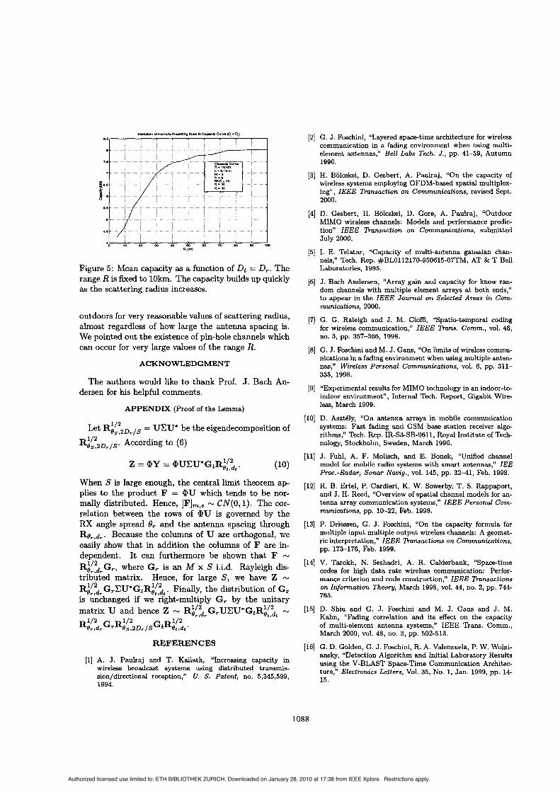
Figure 5: Mean capacity as a function of Dt = D,. The range R is fixed to 1Okm. The capacity builds up quickly as the scattering radius increases.
outdoors for very reasonable values of scattering radius, almost regardless of how large the antenna spacing is. We pointed out the existence of pin-hole channels which can occur for very large values of the range R.
ACKNOWLEDGMENT
The authors would like to thank Prof. J. Bach An- dersen for his helpful comments.
APPENDIX (Proof of the Lemma)
Let Rif2Dr,, = UCU* be the eigendecomposition of
Ri’&Dr/s. According to (6)
Z = @Y = @UCU*GtRi!,:t. (10)
When S is large enough, the central limit theorem ap- plies to the product F = @U which tends to be nor- mally distributed. Hence, [F]m,s - CN(0,l). The cor- relation between the rows of @U is governed by the RX angle spread 8, and the antenna spacing through Re,,d,. Because the columns of U are orthogonal, we easily show that in addition the columns of F are in- dependent. It can furthermore be shown that F w
RiL>rG,., where G, is an M x S i.i.d. Rayleigh dis- tributed matrix. Hence, for large S, we have Z w
R&G,CU*GtRi[,:t. Finally, the distribution of G, is unchanged if we right-multiply Gr by the unitary matrix U and hence Z - Ri[~drG,UCU*GtR~[~t N
R ~ ! % r G r R i ~ ~ 2 D r / , G t R 9 ~ , ~ ~ ’ 1 / 2
REFERENCES
[l] A. J. Paulraj and T. Kailath, “Increasing capacity in wireless broadcast systems using distributed transmis- sion/directional reception,“ U. S. Patent, no. 5,345,599, 1994.
[2] G. 3. Foschini, “Layered space-time architecture for wireless communication in a fading environment when using multi- element antennas,” Bell Labs Tech. J., pp. 41-59, Autumn 1996.
[3] H. Bolcskei, D. Gesbert, A. Paulraj, “On the capacity of wireless systems employing OFDM-based spatial multiplex- ing”, ZEEE Transaction on Communications, revised Sept. 2000.
[4] D. Gesbert, H. Bolcskei, D. Gore, A. Paulraj, “Outdoor MIMO wireless channels: Models and performance predic- tion” ZEEE h n s a c t i o n on Communications, submitted July 2000.
[5] I. E. Telatar, “Capacity of multi-antenna gaussian chan- nels,” Tech. Rep. #BLOl12170-950615-07TM, AT & T Bell Laboratories, 1995.
[6] J. Bach Andersen, “Array gain and capacity for know ran- dom channels with multiple element arrays at both ends,” to appear in the ZEEE Journal on Selected Areas in Com- munications, 2000.
17) G. G. Raleigh and J. M. Cioffi, “Spatietemporal coding for wireless communication,” ZEEE %ns. Comm., vol. 46, no. 3, pp. 357-366, 1998.
(81 G. J. Foschini and M. J. Gans, “On limits of wireless commu- nications in a fading environment when using multiple anten- nas,” Wireless Personal Communications, vol. 6, pp. 311- 335, 1998.
[9] “Experimental results for MIMO technology in an indoor-to- indoor environment”, Internal Tech. Report, Gigabit Wire- less, March 1999.
[lo] D. AsztBly, “On antenna arrays in mobile communication systems: Fast fading and GSM base station receiver algo- rithms,” Tech. Rep. IR-S3-SB-9611, Royal Institute of Tech- nology, Stockholm, Sweden, March 1996.
[ll] J. Fuhl, A. F. Molisch, and E. Bonek, “Unified channel model for mobile radio systems with smart antennas,” ZEE Proc.-Radar, Sonar Navig., vol. 145, pp. 32-41, Feb. 1998.
[12] R. B. Ertel, P. Cardieri, K. W. Sowerby, T. S. Rappaport, and J. H. Reed, “Overview of spatial channel models for an- tenna array communication systems,” ZEEE Personal Com- munications, pp. 10-22, Feb. 1998.
[13] P. Driessen, G. J. Foschini, “On the capacity formula for multiple input multiple output wireless channels: A geomet- ric interpretation,” ZEEE hnsact ions on Communications, pp. 173-176, Feb. 1999.
[14] V. Tarokh, N. Seshadri, A. R. Calderbank, “Space-time codes for high data rate wireless communication: Perfor- mance criterion and code construction,” ZEEE Transactions on Information Theory, March 1998, vol. 44, no. 2, pp. 744 765.
[15] D. Shiu and G. J. Foschini and M. J. Gans and J. M. Kahn, “Fading correlation and its effect on the capacity of multi-element antenna systems,” IEEE Trans. Comm., March 2000, vol. 48, no. 3, pp. 502-513.
[16] G. D. Golden, G. J. Foschini, R. A. Valenzuela, P. W. Wolni- ansky, “Detection Algorithm and Initial Laboratory Results using the V-BLAST Space-Time Communication Architec- ture,’’ Electronics Letters, Vol. 35, No. 1, Jan. 1999, pp. 14- 15.
1088
Authorized licensed use limited to: ETH BIBLIOTHEK ZURICH. Downloaded on January 28, 2010 at 17:38 from IEEE Xplore. Restrictions apply.


![1 Constant Envelope Signaling in MIMO Channels · arXiv:1605.03779v1 [cs.IT] 12 May 2016 1 Constant Envelope Signaling in MIMO Channels Borzoo Rassouli and Bruno Clerckx Abstract](https://img.dokumen.tips/doc/110x75/5f0322117e708231d407b393/1-constant-envelope-signaling-in-mimo-channels-arxiv160503779v1-csit-12-may.jpg)