Embed Size (px)
Citation preview

~Our~alLEVEV
Final Scientific Report on /1 W11TICAL DATA PROCESSING and STATISTICAL OP1ICS ,
c N olasG George pal Investigator
"Grant No. AFOSR-72-2234
Caltech Engineering 136C-F49620-76-C-0021 (Account No. 61297)
California Institute of Technology
Pasadena, California 91125
Period Covered: ! July49'V76 -3 June H578
Final Technica. Report Due: 30 August 1978
C.) Prepared for
LU ELECTRONIC AND SOLID STATE SCIENCES__J
AIR FORCE OFFICE OF SCIENTIFIC RESEARCH (AFSC)
ARLINGTON, VIRGINIA 22209
ZT1"Oi ts toehnlicMITTAL , -- S)
capproved I, / . , t,": "1' ,-Distz-ibt l: •;.• t . , ,, a•O- d ISb
(7b).•"i ][•tf Or t on Opr f Ioe•
Approved fol, pu•ile roloas:O
distribution unlimitead
1 .04 .
F nal Scientific Report on
OPTICAL DATA PROCESSING and STATISTICAL OPTICS
Nicholas George
ABSTRACT
This final scientific report contains a summary of research
at Caltech on the wavelength sensitivity of speckle. Included in
this bibliography are research publications by N. George, A. Jain,
A. Livanos, R.D.S. Melville, C.H. Papas, and J. Roth. Topics
in speckle supported under the subject contract are described:
(1) diffraction by a serrated aperture and (2) propagation in
an experimental test chamber containing a turbulent gaseous
mixture.
Research on the fabrication of gradtig structures for use in
integrated optics is also described. Chirped or variable period
gratings have been successfully made by a holographic process.
Briefly, a waveguiding layer of Corning 7059 glass is sputtered
onto a substrate glass using the Technics MIM Model 5.5 ion-
beam etching machine. Photoresist is coated onto the waveguiding
layer, exposed holographically in an argon or helium-cadmium
laser beam, developed and then ion-milled. Extensive theory and
technique are reported in the bibliography of publications listed
in this report. aumiln- t
Wit UN~ kflI 0
my. ........IV .... ........ ,. ... ........ I . ... ....... .. .
gI IIIITIOU/AIAIJLAtiITT WOU
/ ii VIL a
* :0 4n C'.- I

2
Final Scientific Report on
OPTICAL DATA PROCESSING and STATISTICAL OPTICS
Table of Contents
1. Introduction and Time Period
2. Topics in Speckle
2.1 Serrated Aperture
2.2 Laser Propagation through a Turbulentrasecs Miytitre
2.3 Cumulative Listing of Publications on Speckle
3. Photoresist Techniques for Integrated Optics
3,1 Introduction
3.2 Listing of Publications
3.3 Appended Publications
4. Personnel Supported under the Subject Contract
UD 1473 Form
ii

3
Final Scientific Report on
OPTICAL DATA PROCESSING and STATISTICAL OPTICS
Nicholas George, Principal Investigator
1. Introduction and Time Period
This report describes a program of research in two main
areas of modern optics: Sec. 2. Topics in Speckle and Sec. 3.
Photoresist Techniques for Integrated Optics. The main portions
of research supported under the subject contract were conducted
during the period from 1 July 1976 to 30 June 1977; however a
no-cost extension of the contract date was requested from 30 June
1917 to 3J J,,ne 1978.
2.0 Topics in Speckle
The study of speckle is basically a combining of ideas
in communication theory with those in electromagnetics in order
to set quantitative limits on the performance of general optical
Sconfigurations. In essence, it is a study of noise and resolution.
in compiring the working resolution of single color systems to
white light systems, it is immediately evident that with diffuse
objects the latter illumination is considerably easier to manage.
The reason for this is the deleterious speckle noise which occurs
with the use of monochromatic light. With multi-color lasers, we
have shown that the effect of speckle can be essentially eliminated; jand thus the performance of systems with this type of illumination
is competitive with white light insofar as resolution and superior
both in terms of brightness and in the application of Fourier
optical methods. The general trend of our studies in speckle has
shifted now to the consideration of the questions: "In what ways,

4
if any, can one achieve better performance using separate multiple
tones from a laser rather than white light? What method for
combining single-tone images is optimum in regard to image quality
and resolution?" Coupling of microscopes or any imaging optics
to tiny phutodiode arrays, thence to electronic digital computers,
seems the logical way to study the various correlation possibilities
which may ultimately lead to substantial advancements over current
methods.
A complete bibliography of the speckle publications by the
Principal Investigator and his colleagues is given in Sec. 2.3.
Since this is a final technical report and further effor-t is not
planned, it was felt appropriate to provide a comprehensive list-
ing of the speckle publications which resulted from curt,-actual
support by the U.S. Air Force Office of Scientific Research. How-
ever, it is emphasized that this listing includes research completed
prior to the period of the subject report. The topics detailed
in Sections 2.1 and 2.2 are speckle research supported under the
subject contract period.

5
2.1 Serrated Aperture (N. George and G.M. Morris)
A new class of diffraction theory problems has been
studied. In these an aperture with a rough or serrated edge is
considered. This is in contrast to the usual speckle problem
in which longitudinal phase variations cause perturbations in
the p13se front, i.e., the diffuser problem. It is also different
from the usual blackbody radiator problem, where finite correla-
tion lengths of the aperture illumination are the essence of the
problem.
Under the subject contract, we studied the roughened edge
in considerable detail. While this is only one example, it was
felt to be of special interest as a building block in image quality
studics. Also because of our interest in diffraction pattern
sampling and hybrid (opto-electronic) computers, it was felt
desirable to consider first the problem of finding the optical
transform of a serrated edge. For this problem, we obtained a
closed form solution for the second order moment of the electric
field in the transform plane. As first derived, this correlation
function did not include wavelength variation; but more recently
the analysis has been generalized to include wavelength dependence.
A first report of the analysis together with some experiments
using razor blades roughened with emery paper was presented at
the 1977 Annual Meeting of the Optical Society of America. The
abstract of the presentation follows:+
I

6
ThKI7. Randomly Stirikted Fdges, Lines, and ApeitUxtciNIC"OLAS GFORGE AND G. M. MORKIS,f he JInsrtitut ofOptit-. Unierrsity of Rochesfer, Rodrerzer. ti. Y. 14627.-In auto-matic pattern recugnhslon. flin grain noise and other image-qualitydegiedatlon can give rise to charactet itic optical transforms whichare readily sampled. Related to this Interest, t new clbss of diffrao-s
'tion-theory problems has been snalyzed, As a simple firs! step, wecalculate the optical transform, as well as the Frersnel zone pattern,for a serrated edge. The edge roughness is described by a second-or-der density and its associated chatacteristic function. For convergentmonochromatic illuminasion. we derive an expression for the outputelectric field and fot the second-vrder correlation fonction in trmsaof output position, wavelength offset, edge roughness, and correla-lion length. The effect of the serration is to distribute the energy Inthe transform plane; the large central spike, characteristic of an edge.is greatly suppressed. Theoretical results are also presented far otherserrated apertures. As the roughness Increases, the general tr,:nd isto trade the regular interference ringing for a speckle pattern, Wave.length-sensitivity experiments are described for these serrate, apea-lures, using a tunable dye laser and computer-generated patterns ofcontrolled correlation. Possible application to multitane diffractionpattern sampling is also described. (13 umh.)*Rltoarth rupposnte ti pate by the Air Force Ottfice t ScientUicReasearel.TCaliforana Inasitute of Techuolugy, Pasadena, Calif. 91X25.
This research has been considerably extended since the
above report. However, the abstract above presents the status
at the close of the subject contract. The later refinements
will be described at the 1978 OSA Meeting in San Francisco,
also under sponsorship by AFOSR; and they will be the subject
of a paper in the JOSA.
2.2 Laser Prop agatio.n Through a Turbulent Gaseous Mixture
(N. George and L. Fesselinkl)
A problem of particular interest in statistical optics
is that of propagation through a random, time-varying atmosphere.
For high speed aircraft using laser sensors, one would expect
+ N. George and G.M. Morris, J. Opt. Soc. Am. 67, 1416 (1977).

.7
to encounter both turbulences and shock waves. We seek to obtain
a better understanding of this phenomenon. Recently, L. Hesselink,
working with H. Liepmann and B. Sturtevent, designed and built a
special chamber which, when added to the GALCIT shock tube, gives
one the capability to produce controlled random atmospheres with
fine scale turbulences of 1mm and a decay time of 100 ms.
While considerable experimentation had been performed with
this apparatus using sound detectors and spark-gap light sources,
N. George and L. Hesselink started a study of the effectiveness
of laser light. Viewing the turbulent mixture as a cascaded
diffuser, one would expect a strong wavelength dependence. In
June.-July of 1977, a series of experiments were performed using f
an argon laser operated first at a sinyle wavelength and then
multitone. Both motion pictures and single color photographs
were obtained thereby demonstrating our hypothesis that multi-
tone laser illumination is effective as an instrumentation
technique for wind-tunnel experiments.
The status of this research at the close of effort under
the subject contract is given by the following abstract of a
talk presented at the annual meeting of the Optical Society of
America in October 1977.+
I,

"Ui'LUi. L sammPropAOn FxpePenitsnD U r A (--ntro,
T'ilihulenl Gaseous Mi,,tuje, 1I41IIOLAS GV.KO.VE, Mhe [m.1ffult of Optics. Iiyer ny of RocWhesfer, Rochesr¢ef, N. Y. J4627.
AND LAM iI--IRTtS ItESSFLIN K, (Orlifontia Insiusde of Tean.Alo,'Ls., P11.3,tena. C tif 91125. -In seila, speckle hlstelfesosinetxy
"and many Is-= sys$ems, the effect ofatmiosphetic turbulence 3 adominant issue. In prior wvmik by one of us (LH), an apparatus
has been L:;it4ucted for gcncutiWs a 25 cm cube of tandomlyinhomotgenoous gst in the Gugtenhcim Aerunautli- Latboratories17*in.-niam. shock tube.' in the current study, wo dc•'zclb theust of this tWbulent gas nlaxtwco to study laser plopagation.
Tunable lases and multilon arzon awe useful either as a diAgnosticfor the gaseous mixture of as a means for studying speckle. In thechamber an alray of fine jets in two opposing didewalls is used toinett helium and fieon-12 In a neutrally buoyant mixture. The
optical inde)L of refiaction has sn ,res nuctuatitn ns high as3 X 10" with a lutbultnt mic'otcalc of 2 mmn and an i nteral scale
of 14 mm. llizh-specd motion pictures are shown of the Schllesenilsage of the tuTbulence and of the qpecklc inuae using transformplane stp and pinhole, tespectively. A sunuht.&on of stella speckleimages of a pxoint sourtc or more vonmple~x input can Vv obtained bysimple variations in the lens conrsguration. Piriininvny analysisof the optical tiansen function for this mixture ilt descsibed in the
context of out data using nsonochiomatlc, multitone, and white-Uight lllumination. Some Interzesting color speckk pattcrrss uislg"static" tusbulenx seeons are a•so described and compared tothe index inhomogencitics resulting in the test chamber. (13 min.)
*Reaeach supported in part by th. ALF Fouree Otfie of ScitnUftiItesearth.' L. 5t#mInk. "An Vcsrirnýntal invesUsation of 5rupaoxtion ofWeak Shock Wsý#S in g Ran.kadm Medium.n Phb.D. TheSst (Ctl-toiliatInstitute of Tvchnoloay. 1977).
2.3 Cumulative Listing of Publications on Speckle
Since 1972, the research in Speckle at the California IInstitute of Technology has been supported in part by the U.S.
Air Force Office of Scientific Research. The following pub-
lications have resulted:
A. Subject Contract Period
"Randomnly Serrated Edges, Lines and Apertures", J. Opt.
Soc. Am. 67, V16A + (1977), Nicholas George and G.M. Morris.
"Laser Propagation Experiments Using A Controlled
Turbulent Gaseous Mixture", J. Opt. Soc. Am. 67, 1375A
(1977), Nicholas George and Lambertus Hesselink.
+N. George and L. Hesselink, J. Opt. Soc. Am. 67, 1375 (1977).++A following the page number means Abstract otily.Ii

I9
B. Prior AFOSR Contracts
"Speckle from rough moving objects", J. Opt. Soc. Am. 66,1182 (1976), Nicholas George
"Speckle noise in displays", J. Opt. Soc. Am. 66, 1282(1976), Nicholas George, C.R. Christensen, J.S.- Bennett,B.D. Guenther.
"Topical issue on speckle", J. Opt. Soc. Am. 66, 1316(1976), Nicholas George, Douglas C. Sinclair.�
"Scattering by Glass Microballoons", J. Opt. Soc. Am. 66,1135 A(1976), Nicholas George.
"Speckle Noise and Object Contrast", Symposium on ImageProcessing at Toronto, SPSE edit by R. Shaw (1976), B.D.Guenther, Nicholas George, C.R. Christensen, J.S. Bennett.
"Remote sensing of large roughened spheres", Optica Acta23, 367 (1976), Nicholas George, A.C. Livanos, J.A. Roth,C.H. Papas.
"The Wavelength Sensitivity of Back-Scattering", OpticsCommunications 16, 328 (0976), nicholas George.
"Speckle", Optics News 14, January 1976, Nicholas George,
"Speckle From a Cascade of Two Diffusers", Optics Commun-ications 15, 71 (1975), Nicholas George and Atul Jain.
"Experiments on the Space and Wavelength Dependence ofSpeckle", Applied Physics - Invited Paper 7, 157 (1975),Nicholas George, Atul Jain, R.D.S. Melville.
"Spatial and Spectral Behavior of Speckle in an ImagingSystem", Ph.D. thesis Caltech 1975, Xerox Microfilm75-20,003 by Richard D.S. Melville, Jr.
"Speckle, Diffusers, and Depolarization", Applied Physics6, 65 (1975), Nicholas George, Atul Jain, R.D.S. Melville.
"A Wavelength Diversity Technique for Smoothing of Speckle",Ph.D. thesis Caltech 1974, Xeix Microfilm 74-XXXXXXXXXby Atul Jain.
"Space and Wavelength Dependence of Speckle Intensity",Applied Physics 4, 201 (1974), Nicholas George andAtul Jain.

10
"Speckle Reduction Using Multiple Tones of Illumination",Applied Optics 12, 1202 (1973), Nicholas George and AtulJain, and abstract in J. Opt. Soc. Am. 62, 1356 A(1972).
"Speckle in Microscopy", Optics Communications 6, 253(1972), Nicholas George and Atul Jain.
3. Photoresist Techniques for Integratel Optics
3.1 Introduction
A really spectacular series of research accomplishments
were obtained by a group (listed below) of sciertists working
on chirped-gratings as demultiplexers for dielectric waveguides.
This topic of research was partially supported by the subject
grant and partially supported by a separate grant from AFOSR with
Professor Ammon Yariv as the Principal Investigator.
The portion of the research support drawn from the
subject AFOSR contract included full support of Dr. Alexander
C.R. Livanos as well as considerable laboratory facilitation for
stabilized holography. Film supplies and other specialized
electronics were also supported by funds from the subject contract.
In this cooperative research, support for Dr. A. Katzir, one of
the principal contributors, as well as that for Yariv, Hong, and
Shellan was not derived from the subject contract. Appropriate
accredition to the U.S. Air Force Office of Scientific Research
is contained in the resulting publications listed below in Sec. 3.2
and appended in their entirety in Sec. 3.3.
3.2 Listing of Publications+
"Fabrication of Grating Structures with Variable Period",Optics Communications 20, 179 (1977), A.C. Livanos,A Katzir, A. Yariv.
+Partially supported by the subject contract.

11j
"Chirped-grating output couplers in dielectric waveguide4",Applied Physirs Letters 30, 225 (1977), A. Katzir, A.C.Livanos, A. Yariv.
"Chirped Gratings in Integrated Optics", IEEE J. QuantumElectronics qE!-13, 296 (1977), A. Katzir, A.C. Livanos,J.8. Shellan, A. Yariv.
"Chirped-grating demultiplexers in dielectric waveguid!s",Appliad Physics Letters 30, 519 (1977), A.C. Livanos,A. Katzir, A. Yariv, C.S. Hong.
"Linearity and enhanced sensitivity of the Shipley AZ-1350B photoresist", Applied Optics 16, 1633 (1977), A.C.Livatios, A. Katzir, J.B. Shellan, A. Ydriv.
"Broad-band grating filters for thin-film optical wave-guides", Applied Physics Letters 31, 276 (1977), C.S. Hong,J.B. Shellan, A.C. Livanos, A. Yariv, A. Katzir.
"Simultaneous exposure an6 development of photoresistmaterials: an analytical model", Applied Optics 16,2612 (1977), P. Agmorn, A C. Livanos, A. Katzir, A.- Yariv.
3.3 Appended Publications in Integrated Optics

12:•"
Volumne 20. nunibF 1 0111 ICS COMM UNIC'ATIONS January 1977
FABRICATION OF GRATING STRUCTURES WITH VARIABLE PERIOD*
Alexander C. LIVANOS, Abraham KATZIR and Arnson YARIVCuifnoruia lnsIgtute of Trerhnso'gy, Payadena, ('alifornie 91125, USA
Received 15 October 3976
Plsotoresisi gratings with variable period have been fabricated by recording the intCrference pattern of a collinmated laserbeam with a converging one. Tire period variathitn as a function or position,, as well as tie wavelenigth dependent focal pro-perties of the gratinps, has also been analyzed.
Periodic optical structmes, specifically those pro- To analyze the characteristics of cl -ped gratingsduced by corrugation of dielectric waveguides Il3, consider the geometry shown in fig. 1. The holographic
have aheady played an important role in thin filIr and plate is located in the z r 0 plane, the angle of incidenceintegrated optics. Such periodic devices include: grab of the plane wave is j 0, and the angle subtended by theing couplers for dielectric waveguides 12,3,] distribu- collimated beart and the bisector of the convergingted feedback injection lasers [41, Bragg filters [5] and beam angle is 0. lise interference pattern is recordedrefiectors j6j. •er a distince s on the film plate. The converging wave
For many projected applications it will be necessary is generated by a cylindrical lens of focal length f andto produce gratirgs with appreciable and controllableperiod variation. Some of these applications involve
acousto-optic pulse compression, broadband opticalfilters and reflectors and optical multiplexing.
In the following we report the results of experi-rrents which resulted in the fabrication of photoresi '
gratings in which the period varies from a value of0.8 pm to 1.3pum in a distance of 6.5 mm. These pho- c#tircotorsist .chirped gratings can be used as masks for repli- Lent
cation by ion or chemical etching onto "working" sur- -
face; like GaAs, LiNbO 3 , glass, etc,The fabrication of gratings on a substrate commonly
involves the rec;ording of an interference pattern oftwo collimated laser beams on a thin photoresist layer 1
and the subsequent etching through the photuresist I /-Ho'oQtort, Platema.k- Ill). To generate a similar mask with a Variable •/, •;
period the photoresist is exposed to the interferencepattern of a collimated beani and a converging one.This method has oseen proposed in the past to fabricateholographic lenses [7], but its realization in the domain Pit [of integrated optics has not been explored.
* Work supported by tre Air Force Office of Scientific Research. Fig. 1. Chirped pating recording ararngement and geometry.
179
- 13
"Volume 20. number I OPI ICS COMMUNICATIONS January 1977
width d, and the focus is located at point P(xf, zf). X *-" z' sin 0' - z sin (WO). (8)Simple geometrical considerations relate the focal
line coordinates with f, s, d, and 0, namely To generate chirped gratings on photoresist the•Cos 0 * Cos (2€0 4579 A line of an argon laser was used to produce twoos0 (20) (=) collimated beams. The intensity of each beam was3 mW/cm 2 and the angle between them was 0 = 26.50.
and A cylindrical lens of focal length f- 10 cm, and widthd - 2.4 cm was inserted in one of the beams such that
Xf =- tan (2) the intei ference pattern extended over a distances
where = 0.65 cm on the photoresist coated substrate. A neu-tral density wedge was introduced before the cylindri-
tan-l( d/f) cal lens so :"at the intensities of the plane and converg-ing wave were identical on the film plane.
is the convcrgence half angle. The fabrication of chirped gratings was demonstra-The electric field on the film plate (z = 0) is the sum ted in a layer of Shipley AZ 1350J photoresist which
of th reference wave and converging one and is given by was diluted 5:1 with thinner. The photoresist was=-. A e s (I O' spun coated at 6000 ipm on a well cleaned microscope
Ex, Z 0) A p sslide, and then baked for 25 min at 90 0C. Best results
f2 + z21/2 wee obtained when this photoresist was exposed to+ a exp ik{(x - x f ] (3) the interference pattern fur 125 sec (corresponding to .
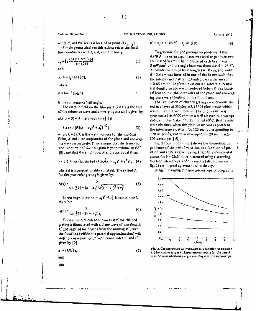
where k = 2r/X is the wave number for the incident 120 ma/cm2 ), and then developed for 20 sec in AZ-fields, A and a the amplitudes of the plane and converg.. 303 developer I 10].ing wave respectively, If we assume that the transmis. Fig. 2 (continuous lines) shows the theoretical de-sion tunction r ofr " -ic '-1•,, m .. it p-rcnrtional to EE" pendence of the period variation as a function of po.181, and that the amplitudes A and a are equal then: sition and angle as given by eq. ",.The txperimpntal
points for 0 =26.50 %.. re measured using a scanning311 + cos {/x sin (•0) + k!(x - ., 4-.z2 (4) electron microscope and the results (also shown on
fig. 2) are in good agreement with theory.
where P is a proportionality constant. The period A In fig. 3 scanning electron microscope photographsfor this particular grating is given by: . --
sin (10) + (X -- Xf)l_(XX )2+ . 1!
In .ur experiment (x - xr) • 4 (paraxial case),
there fore
A _ _ _ (6) Losin (0)+(x- xIz)
Furthermore, it can be shown that if the chirped o6-grating is illumilnted with a plane wave of wavelength 04o_-V and tngle of Incidence (from the normal) 0', then
the focal line (within the partxial approximation) will 0.2t
shift to a new position ' with coordinates x and r' o --- 0 - I ,-".4 -3 -2 -1 0 1 2 3 4given by 191 x (mm)
I( Fig. 2. Grating period (A) variation as a function of positionz (iV)tf (7) (x) for vaduus angles S. Experimental points for the case 9and 26.5r were obtaine• usinS a scanning electron microscope.
180
,I.

14-
Volume 20, number I OPTICS COMMUNICATIONS January 19? 7
Ia
(b)
SFig. 3. Scanning electron microscope photographs of two legions ef the chirped grating. (a) The grating P't poitios x - -35 mm
corresponding to a period A (-3.5)- 1.43 pni. (b) The grSttng at x - 3.5 mm with period A (3.5) 0.82 jrn,
.J

-15
Volume 20, number I OPTICS COMMUNICATIONS January 197?
grating and the resulting focal lines, separated by a dis-tance of 5 mm, are shown in fig. 4. The separation pie-
dicted by eq. (7) is 5.1 mm.To summarize: The fabrication of chirped gratings
ini photoresist has been demonstrated and some of theirproperties studied. In addition, theoretical expressionsdescribing the transmission function of these gratingshave been presented [eq. (4)]. as well as the periodicityas a function of lateral displacement [eq. (5)]. The varia-lion of the focus as a function of wavelength and inci-dent angle was also studied. The experimrental resultsare in agood agreement with the theory.
An experiment which involves the use of a chirped
grating in optical multiplexing is now in progress.
References
511 H.L Garvin, E. Garmire, S. Somekh, H. Stoll andFig. 4. Focal line separation obtained from simultaneous il- A. Yariv. Appl. Opt. 12 (1973) 455.
lumination of a chirped grating with 6328 A and 5014 A 121 H.L. Dakss. L Kuhn. P.F. Hieidrich and B.A. Scott, Appl.
wavelengths. Phys. Lett. 16 (1970) 523.11] i.J. Clair, J.M.C. Jonathan and J.L. Stehle, Opt. Commun.
13 (1975) 183.of die g,,atihg period -, c = -3.5 mm 1A(-3.S)) and 141 M. Nakamura, Ht.W. Yen. A. Yariv, E. Garmire. S. Somekh
x = 3.5 mm [A(3.5)] are presented. and H.L Garvim,. ApI. ; Lets. 23(1973) 224.
"T.o illustrate the variation of the focus as a function 15] D.C. Flanders, H. Kogelnik, R.V. Schmidt and C.V. Shank,Appl. Phys. Lets. 24 (1974) 194.
of wavelength a chirped grating was ilumninated simul- 161 H. Stoll, A. Yariv, Opt. Commun. 8 (1973) 5.tancously with collimating light from a He-Ne laser 171 G. Rogers, Nature 166 (1950) 273.(6328 A) and the green line (5014 A) from an argon 181 R.A. Bartolini, Appl. Opt. 13 (1974) 129.laser. Both beams passed through a spatial filter anil 191 J.W. Goodman, Introduction to Fourier Optics (McGraw
a collimating lens, -nd were incident on the grating at Hill, San Francisco, 1968), 214.1101 S.L Norman and M.P. Singh,, Appi. Opt. 14 (1975) 818.
an angle 0 0'. A ,creen was positioned behind the
I!182

- 16
Chirped-grating output couplers in dielectric waveguides*A. Katzir, A. C. Livanos, and A. Yariv
Coaifornia Institute of Techriology. Pasadena, CofiVorrio 91125(Received 4 August 1976. in final form 29 November 1976)
'nit~ paper reports orn the method of fabrication and first experifnents of rhirpod (vxriable period) 6ratings
in a dielectric waveguide. Such gratings, which are propoced as a new optical blidding block, arc used ii,
this work as focusing output coupicri.
PAC'S numnbers! 9440.Wv, 42.90.Lt. 42.92.-1 n, 42.80,Fru
Periodic perturbations such as surface Corrugations length of the recorded vpattern (see Fig. I). One canare often used for inputt or output couplers In dielectric assume that the transmnission junction i of the record-waveguides.'I A guided optical mode cat) be coupled out Ing mediumn is propotAionaT to EE' 3and derive theby surface gratings a, an angle 4) with respect to the following expression for t:film surface, where 41 is determined by the propagation t-( + cnsjkz sin( 16) 4 h{(Z -. Z,)3 4 x7J' "}), ()constant A of light in the waveguide a"'i by the periodA. If the output coupler conSiStS Of a grating with a where 0 is a proportionality factor. The period AWzvariable period A(z). then, for a given propagating can now be writtenmode, different parts of thc coupler would launch thelight out in different directions. It is conceivable that AW iz) .all these directlons will Intersect at a conimon point in A~~64(e-~)(z- 111~~T 7I (2
sueh a way that the light wIll be focreed outsidu the The period is therefore a function of x~, 0, f, d, aaid L.
%:avegulde. Each of these can be changed, independently, so as toitTo ensure this type of focusing we fabricated the give a different variation A(P.).
graiting holographically by exposing a photoresist layer The interference pattern described above was used,on top of the waveguide to the Interference of a collim-int-. as discussed above, to fabricate chirped gratings oned laser beam and a cylinidrieally focused beanm. The top of sputtered glass waveguides.photoresist grating which renm~.ined after development Consider next the dielectric waveguide shown sche-served as a mask thiough which the grating was re- mtclyi i.2 h ufc ftewvgieiplicated, by Jioo etching, onto the waveguide surface, coruated oi e aig l.Tength face and the orrugztldo isto
*Similar exposure schemes have been used for the is given by Eq. (2). For a given propagating mode, withfabricVion of holographic lenses.' a proipagaton c'onsitant 0 = kri cos9, the ih ope
The setup used for the fabrication of chirped gratings out at a point z' along the grating will propagate Wn airis shown schematically In Fig. 1. A thin layer of re- according tocording material is exposed to the Interference pattern epikf.'z+ fwc'-k(' X)of a collimated laser beam with a converging beam.The coniverging beam Is generated by a cylindrical lens where kU43-27r/A(z'). If we define B0 nk,()=Pof focal length f and width d. The bisector of this beam .- 2v/A(0) and 0,, rk,(L) =,8 - 2i/A(L), It ckn now besubtends an angle 8 with the collimated betm. The shown thait the light will bc focusedr by the chirpe4coordinates x, and tf of the focal polint P are simple grating at a 2cint P(xr, z,l) who."e coordinates are givengteom~ri-ýrlal functions off, d, 0, and L, where L Is the b
by0 , -u (k - 0 2Pk i~ /r" '
Z l = h j l _ _6 1
FIG. 2.Geometry for a chirped grating etched on the top suir-face oE a wavegutdo of index wn. 7%e substrate has an index n3,aod x,, In the Index of reftaction of air. A wasvigtide mode will
Y10l. 1. Rteoordizsg arranigem,7.t and Xournotr; fo- the ftbrica- focus at potint Pjxxzý de,'endtbtg on tht wavegutd#%, the cbirption of chirped grnadogs. of the grating. and4 the wavelength.
226 Afipllrd Physic, ( eiiect. Vol. 30, No. 5. 1 March 1977 2215

an tings were transferred onto the wavegulde using the
too same ion beam etching machine.
•* We calculated the position of the focal ioInt P(xN, Z,)for various lines of the Ar" laser. For each line, and• .4 5M,-
_, for the wavegide used, wc calculated the propagationconstant and obtained x. and sr. The results of thesecalculations are shown in Fig. 3, both far the chirped
40 hp gratings used and for other chirped gratings.""- 5-
E 7 - 2. In the experiment we used a prism coupler to couplelight from an Ar" laser into the waveguide. The light
"- _______coupled by the grating was found to focus to a line nor-• *to 0o Io 20 real to the xz plane. The x-z coordinates of this line
were measured for various lines of an Ar" laser. TheFIG. 3. E~xerimental and theoretical results of the focusing of experimental points are also shown in Fig. 3, and are
jight for the corrugated structure used. The solid line repre- fudtfitwl to the alsoretical curve. 3t hod be
sents the theoretical position of the focus as s function of found to fit well to the theoretical curve. It should bewavelength. The solid dots represent the focus of the promi- noted that the focal point moves 1. 2 cm when the wave-neat linen of the Ar' and HeNe lasers. The large circles are length is changed from 4579 to 5145 A.the experimental points for these wavelengths as measuredwith a two-dimensional translation probe. In conclusion we demonstrated in this work the fab-
rication of a chirped-grating output coupler in an opti-cal waveguide. This structure focuses light outside the
x• -[(k'-9) 2/ 0 ,1z•. (4) waveguide while simultaneously separating betweenpropagating beams of different wavelengths.
The focal-point coordinates thus depend on the chirp ofthe gratings, on the waveguide, and on the wavelength Various integrated optics components are based on aof the guided mode. Sonme examples of the variation of periodic perturbation. Such components as narrow-
the focal point with wavelength and with chirping are band reflection filters," beam splitters, " distributedgiven (for a particular waveguide) in Fig. 3. feedback lasers,' distributed Bragg reflectors, 0 and
grating couplers' are all based on a periodic perturba-To illustrate the focusing effect we designed a wave- tion. Very often the perturbation takes place as a sur-
guide to focus light a few centimeters away from the face corrugation. The addition of a new variable, li.'waveguide. We first used iun bJputterllng to deposit a cMrp~ni, into these components is bound to open uplayer of 7059 glass on a regular microscope slide, new possibilities in their utilization.The rclractive index of the waveguide was determinedby the prism coupler method" and was found to be The authors wish to thank Proiessor N. George for1. 565. The thickness of the deposited layer was deter- many helpful discussions and D. R. Armstrong for his
mined by Sloan Dektak. The thickness was 1.35 Xm assistance.
and was found to be uniform within 5% over the regionof interest. A thin layer of undiluted AZ-1350B Shipleyphotoresist was then spin coated on the waveguldinglayer at 3600 rpm. The photoresist was prebaked at *lesearch supported by Air Force Office of Scientific125"C for 25 min and then exposed to the interference Re.• npaxhJ
pattern between the collitrated beam and the converg- M.L. Dakss, L. Kuhn, P.F. licidrich. and B.A. Scott,Ung bean. In this Axporiment we used the -4 579 A Appl. Phys. Lett. 16. 623 (1970).
""G. Rogers. Nature 166, 273 (1950).line of an Ar' laser, with 1.0 mW/cms per leg. The 3l.A. Basrllni, Appl. Opt, la, 12ý (1971).other variables were 0 =94, 5%, F= 1.33, and L = 1. 1 4RI. Ulrich and II. Torge. Appl. Opt. 12, 2901 (1973).cm. The photoresist layer was exposed for 60 see, and 6D.C. Flanders, H. Kogelnik, l-.V. Schmidt, and C.V.then developed for 10 sec in AZ-303A developer. Shank, Appl. Phys. Lett. 24. 194 (1974).Chirped gratings were thus obtained and the grating 'K.S. Pennington and L. Kuhn. Opt. Comm. . 3. 387 (1971).
S1K. Aiki, M. Nakamnura, J. Umneda, A. Yariv. A. Kattir.period was measured and found to vary between A(0) and Hl.W. Yeu, App). Phys. Leat. 27, 145 (1975).=r0. 295 gim and A(z= 1.1 cm)=0. 33 tim. The photo- 6W. Ng, H.W. Yen, A. Katxtr, 1. Samid. and A. Yariv,resist was then baked in vacuum, and the chirped grat- Appl. Phys. L.ett. 29. 684 (1976).
2W6 Appl. Phys. Latt., Vol. 30, No. 5. 1 March 1977 Katzir. LUvarns. and Ysriv 226
Ll

296 IEEE JOURNAL OF QUANTUM ELECTRONICS. VOL, QE-1 3, NO, 4, APRIL 1977
Chirped Gratings in Integrated Optics
A. KATZIR, A. C. LIVANOS, J. D. SHELLAN, AND A. YARIV
Abstruct-GrtinIL with varlab" perils (chipe~d "iatings) have beenfabricated by recording the Interference patter of a collimated lasbeam with a converging beam generated by a cylindrical lens. An anal/.yals Is presented for the behlvlor of the chirjid gratings as a functionof wavelength, the angle between the Illuminating beams, the F numbesrof the lent, ard its posltion- To calculate the power radiated into alt,the coupled-mode equations ane solved tot the cae of a wavguide withchirped surface corrupation. Experimentally, chirped gratings have ',La
been etched on the surface of an optical waveulde and used to coupleISlMt out of the wavegide. It wal found that the light was focusedoutside the wavegulde, and the fraction of the power radiated into aircompared favorably with the theoretical calculation, The focal point L /outside the %%,vegFdde was found to move by about I cm when the L •Recording Plrait*wavelength was changed by 500 A-in agreement with tleoretical
estinmte
1. INTRODUCTION Fig. 1. Recording arrangement and geometry for the fabxication of
P ERIODIC STRUCTURES, and in particular corrugated hirpcd gratings.
structures, play a sigrificant role In integrated optics [ i.Corrugated waveguides serve as narrow-band filters, which re-fiect wavelengths which satisfy Braggs iaw 2].Such icficc- - cos 21tors may be incorporated in laser ttructures to form distrib-ted _ 2 osfeedback lasers [31 or distributed Bragg reflectors 141. Peri- X" 2 sin 20 os --odic structures with longer periods have been used to couple dbetween guided n'dces and air, such as in the cases of Itiput and
or output coupl, rs (5]. L0o( 10In this paper, we consider the problem of gratings with 2) Jo
large and monoloni, variation in tht period. We describe a /sin (2)method for fabricating such chirped gratings, present a theory
for treating them, and present experimental results demon- wherestrating some of their unique applications.
II. GRATING FA14RICATION CONSIDLRATIONS 2f,The gratings are fabricated, as in the case of uniform grit- is the convergence. halh-angle. We note that in (1)x is always
ings, by the interference of two laser beams. The period chirp negative, while zf can take negative or positivt values depend-is obtained by cylindrical focusing of one of the two beams, ing on the angles 8 and 0.as sbown in Fig I. The recording plate is located at the The electric field in the recording plane (x = 0) Is given byx - 0 plane, the angle of incidenrc of the plane wave is 0/2, the sum of the reference wave and converging one and is givenand the angle subtended by the collimated beam and the bybisector of the converging beam angle is 6. The interferencepattern is recorded over a distance L on the recording plate. I(x 0, a) = A exp - ikz sin (0/2)The converging wave is generated by a cyiindrical lenz of +o a exp k j {I(r - r)" +xj] at:} (3)focal length f and width d, and the focus Is located at point where k - 2yrrA is the wavenumber for the incident field, anaP(r1 , if). :A and a e the amplitudes of the plane and converging wave,
Simple geometrical calculations relate the focal line co- reanect ley t we an tume ta the toantand convfncion wvordinates with 1, L, d, and 6, namely respectively. If we assume that the 'transirlstion function of'the recording medium t is proportional to EE* (61, and that
A a a, thenManuscript received November 16, 1976;revised December 16,1976.
Ths research was sij~im~d _% AFO0SR. The work of one of the t - [(1 o {kzsi (0/2) + (4)X~r~jjauthorn (1. 0. S.) was supported In part by the He'tz Foundation.""The cuthma are with te Calloroia institute of Teuolo.P- wher P. Is a proportionalty constant. The period A for this
* dma, CA 91125. particular grating Is given by
'I'

KATZIR ef of.: CHIRPED GRATINGS IN INTEGRATED OPTICS 297
A(z) = -___________
In the pa-axial appioximation (z - zf~l <(xj, (4) and (5)reduce to S~Fr .... __ ___+
+ cosl kP + (ksin(0/ 2 )-kz ) ý z
+ •s+ :z.,+1.j~l. (6) ... .-
if00. 0 4 0 8 1The corresponding expression for (5) is therefore o 2Cm) 08
Fig. 2. feriod variation as a function of the F number of the c9n-
A(z) - (7) verging lens (F - fid). The angle .- 60 is suitable fOr Variationssin (612) + (z -zf)Ixj' of 0.8-0-4 ezrn over a distancc of I cm.
It is seen from (1), (2). and (5) that the period variationA(z)dependF on theF number of the lens (F=_fd), and that0 i: the angle subtended by the collimated beamn and the M-0secioT of the converging beam angle, X is the wavnltngth ofillumination, and L is the length of the grating. 0 4ý
The dependence of the period variation on F is illustrated .o.
by Figs. ý and 3. In Fig. 2, the angle 0 is set at 600 and the . *1grating has a total leng..h of I cm. For various F nminbers,Fperiod variations from 0.8 jim to 0.4 ym are obtained. The 7lower the F number the greater the period variation; higher _q -
F numnbers result in sinallert and more lincar period variations,In Fig. 3, the angle 0 has the value of 900. Here the maxi-mum period variation is for an F= I lens and it ex'ends from ---- -----0.45 to 0.28 pum over a distance of 1 cm. It is noted th.t Go 0 2cm)
large values of 6 produce smaller period variations. Fig. 3. Period varialion ac a function of the F number. The angle 6
This particular point is illustreted in Fig. 4, where an F- has a value of 90' and the range of period variation is from 0.45
1.33 lens was chosen and 0 was varied from 450 to 120". to 0.23jum., again over a distance of'I cm.
Again the grating extends over a disstance of I cm. It is seenthat with 0 - 120%, the period varies only by 0.05 pro, while .1-----0 • ••,
for 0 = 450 the period variation is 0.5 tum. F-, 3.1The linearity of the period variation As a function of grating .o. ,
length L is shown in Fig. 5. ii shumid be noted tha, the .
beginning and end period is identical for all values of L. 06Again the F number is 1.33 and the angle 0 is 90°.
111. WAVFGUIDIE COUPLING C 5
Chirped grating etched onto a dielectric waveguide results 0.
in a simultaneous output coupling and focusing to a pointP(:cx, z,), which will vary as a function of the modes sup- oc_... . . . ...ported by the waveguide and the wavelength of the guided 00 02 04 06 6.8 "t -modes. z 1,cm)
Consider the geometry described by Fig, 6. When the Fig. 4. Period variallun as a function of a (the an;.. letween theuidmode is propagating unperrubed n the wavegude, plane wave and the bisector of the converging wave). The F num-
guided bey of t1- tent sh 1.33 and the illumination wavclc;gth is 0.4579 jun.its z dependence is given by e"41", where 0 - kn€j coa & 1. The mcording distance Is kept constant at I cm.When the wave reaches the perturbation, the radiated modewill have a z dependence given by e-Cirs. At point z x 0, k, 2w
i given by k,(L)fl- 21 (9)
kM(O)"- (8) I can be shown that by a) matching the tangential coin-ponent of the electric field inside and outside the wivýSulde,
and at L b) requiring that JO - k, + k2 outside the wavegulde, and c)

IEEE JOURNAL OF QUANTUM ELECTRONICS, APRIL i977
05- -* 6328pt.m
F 33- .550opm&,' d)'m 5145,.ni
L •4 880#.i s0
04 4579,..m
-100i .o
Chtp
7 2.0 -,33- 30,mrn
M--34-9M.O"'---6T ---- - i - --- . . ..08 to " .4 .z tcml -20 • - --- t•-O
Fig. 5. Period variation as a function of recording distance L. The Z "c;M)tcial amount of chirp is the same for all curvet; the linearity of Fig. 7. Locus of the loci of various wavelenghts for difftrent chirps.viriation is seen to improve for large values of L. Thn angle 0 * The grating is located between z - 0 and a - 1.0 cm Pt x - 0. A(0)50% the F nurnber Is 1.33, and the wavelength is 0.4579 oam. is the longest period and AOI cm) is the shortest. The wavegulde
mode is traveling in the positive z direction.
the separation between the different wavelengths and the
* larger the distance of the locus of the focal points from the
waveguide, and c) if the. average period of the chirped grating-In is increased the focus will sh~ft towards greater values of s.
-\JVVW# In, T V. CALCULATION OF POWER OU-1utu
DISTRIBUTION FOR CHIRPED GB"LTINGS
I ----'-L • In the previous section we discussed the characteristics ofthe chirped gratings and some of their properties. To com-plete our theoretical discussion we present a cakulation of
(.2 the actual power radiated into air by a chirped grating.To analyze xhis problem we expand the electric field of the
perturbed waveguide in terms of the guided modes, the sub-Fit. 6. Gomet.y for a chirped grating etched on the top surface of strate modes, and the air modes. This work is essentially an
c wvvejulde of index nI. The substrate has an index n2, and n3 extension of Marcuse's work 17, in so much that in ouris, Uste i -"fr.......n of air. A. waveaulde roode will focusat point Pix)., x)). depending on the chirp of the gratirng and the case the waveguide is no longer symmetric (we include thewavelength. . substrate). Our notation and method are similar to his.
We present a closed-form solution for the power radiatedassuming that the transmission function for the grating is into air by a chirped grating, and illustrate the solution withgiven by (4), the light. will focus outside at a point P(xx, zx) examples of gratings where we vary the amount of chirp andgiven by the wavelength of the guided radiation.
k. (0) L Consider the geometry and notation as presented in Fig.ko) ~ k2 I(0)L 4- k',(L .(10) 8(a). Using the results obtained by Marcuse 181, we have'4(0 v-'" ýk(O. )- k, (L) vr'• - _4-0-0 fol the TE guided modes
and &Y = Ae-4 Z. for x > 0 (12)k O - -EX.) .(1) NA co xx-•--snr , for0;>x >-d
The fo~uslng effect and especially the variation of the focus (13)as function of wavelength and period variation is illustrated byFig. 7. Taking n5 1 .565, 2- 1.51, n• - 1.0, and a wave- ,-A xd+.snxdI•s for x <-d (14)guide thickness of d - 1 35 pm, the eigenvalue equation for KA was solved for wavelengths ranging from 4500 to 6500 A. whereHaving thus determinitd P for the unperturbed wavegulde, wecalculate k,(O), k5(I.) for various ranges of period variation. K M (47 kA -. 02)t12 (15)It can be seen from this figure that a) the larger the period(variation the closer to the waveguide the locus of the focal (0 1110)1/2 (16)
" the smaller the period variation the larger 6 % -0 ke)1"2 (17)

21 21
KATZIR rtaJ.-. CVIRPED GRATINGS IN INTEGRATED OPTICS 299
I WL 4
II~n 1 Woveguide n' +a* (26)i d 4 G)
n2 Subtifolt ln2and Fs can be chosen arbitrariy. Following ihe conventional
(a) b) procedure. FI and E3 are chosen so that tile two radiation
Fig. 8. (a) Goornetry for a dielectric waveguld¢. (M) Dielectric wV*- modes are orthogonal to one another.guide with a chlptd ITatinS etched on the top surface.
wher ,, n2, n3 arc the indiccs of refraction of the wave. F 3) sip 2o d -I (o P ) cos 2o(
guide, substrzte, and air, respectively, k is the wavenumber in [ P)air, and Al describes the a dependence of the electric field. Itshould be noted that the factor e f°r e-1 'O has been suppressed + 2(P/1AX0 2 - P2 X - 4A1 cos 2odin (12)-(14). Furthermore, the constants a ') and S can be + WP=2=&s - AW)2 ll4 (27)determined by the cigenvalue equation
(
whereec(- + d)tan icd d) (18) P5p-p)(~ () *p)fK2(- -r P ')p 2,P ~. g.(p) •. (' ') dx.
The amplitude of the electric field A Is related to the powercarded by.the mode, namely Again the factor e Wr €-C's has been suppressed in (20)-
4x'cjj,1 P (22). In this work O is an inherently positive quantity.A - (19) Next we expand an arbitrary TE elect!ic field for the pcr.
I jd + 11- + 1/5] (Jc + P2) turbed waveguide in terms of the discrete guided modes and
P ,.- the continuumn of both substrate and air modes
where P is the power carried by the mode, d is the thickness of dECretC afthe guide, w is the radian frequency, and Po is the magneticpermeability of vacuum. + h(p.z) &a(p)dp (28)
These guided modes occur for kn2 <I A! < k,--. For the nregion knr < 1I1 < kn2 the substrate modes Lxist, and, finally, cdd (i, -nt)
in the region 0 < 101 < kns the TE air modes ofthe continuum where &,, are the discrete guided modes given by (12)-(14)occur. For the purposes of this discussion we consider the air for the n values of I determined from the eigenvalues of(18).mode sin"e we want to calculate the power radiated by the Similarly, 9' are the air modes given again by (20)-(22),waveguide into the air. Reference [81 gives the electric where even and odd refer to the choice of F2 and F1 (27).field as !r ate the suhstrate modes which have not been presented
,y - C•J.os Ax + (o/uA)F sin Ax] explicitly since they do not affect this calculation. It is tobe noted that the previous expansion for the total electric
for X ;0 0 (20) field Ey is possible since the set of eigenfunctions is comn-
a C,(cos ox + F, sin ox) plete. The calculation is simplified due to the orthogonalityof the modes as a result of the choice of Fl. Furthenrore,
for 0=x>-d (21) this expansion is similar to the one present in [7], as welSC, [(cos ad - F, sin ad) cos + d) as the notation and the method used to solve this problem.
To determine the value of h(p, r), we substitute (28) into-+ - (sin ad + F, cps ad) sin p(x + d)), the Helmholtz wave equation, multiply by ,*, integrate overp ( x, and, using the orthogonality relations, get a differential
equation for h(p, z). This differential equation Is then con-for x <-d .(22) vetted into an integral equation following the procedures of
i (nik" .- .)II3 (23) (71,namely
o = (n~L2 - P62)1I2 (24) h (p, z)i= Q(p) + R(p) exp 2iVz + -•
.=(12k 20lrJ (25).4kwhere C, ia again related to the power carried by the mode •af - i
c; - "---- cos ad - F, sin od)'nod)'l where --
S ... • I ", I' I I I 1 •1• 'i : ['u

22
300 IEEE JOURNAL OF QUANTUM ELECTRONICS, APRIL 1977
H(P, z) C" ~~~f~ (Z)f 40(p)bAn Cbcx r2wgP dp I~h*(p.L)l'""prPdiL ed , )d t n f, )
f&D~ dp(p ~f ~into sit odd""+ ( dp',(p)
An'&,(p') dx - dP'h (P, z) + lh2 (P, 0 2 ...... • (36)
"f- &'(p) A n'&<p') dx (30) The term involving Lhe integration with respect to x gives
the friction of the air mode radiated into the air. Further-
where An 2 describes the deviation of the cornrgated-guide more, the boundary conditions require'that
dielectric constant from that ot'a uniform waveguide. h*(p, z = 0) 0To solve the previous integral equation, we use the Born
approximation. In ether words, we use Cn(0) = 60. instead )of C,(z) and set g(p. r) - h(p, z) = 0, in (30), resulting in h + f jH(p, -) di
.1k 2F-00z &0 h-Cp, z -L)=- 0 (37)n(,) -a(p) 80 dt. (31) (3.)
2W.U h-j-L~ ex-2i0H(P)4 xp~pz. (38)In the next step, we assume that the perturbation of the 2-. L I
snide from its ideal shape is on the top surface of the guide, Using the previous conditions and (32), (12), and (20), we get
as shown in Fig. 6(b). By taking a sh.llow grating and seiiin( -
x - 0 in the previous equation, we get h'(p, L) -* - ACr (39)4itjLP
H(p.j) - nI -nj)f(z)V"(0,p.,Z)o(O,z). (32) k(n? -n-)2 P h-(p. 0) - - -' #-A C, (40)
Equstion (29) can then be divided into parts as follows: where
h+=Q- ' H(P.{)dI (33) *÷=€÷([.L)= ffAz)expi(ft-fi)zdz (41)
wm[ F andLh20 R o 2it ex - i H (p, ý) d • exp 2i/•z (34)
such that , L) - 0 f(z) exp -i(P + 00) z dr. (42)
h - k÷ + h-. Using (19) and (26) we can calculate h'(p, L), namely
Recalling (28). we note that the contribution to the total k(nI - n4,)1.+1t X2
electric field arises from the product of h(p, ) - &'(p, z). I' g I t[d + Gho + 10601 (4 + 8•) wlThe t dependence of &'(p, z) is e-4 0". If we consider the J 0dependence of the product, then •(cos ad - F, sin ad)" 4-- (sin od
I" ]h(p, Z) &,(P,X) h exp -1 + R +-S eodece) + ,cs2I) + F2(3
e exp-21P1H(pj)dd cxpi:z. where Kg,to, 6, •eff to the zero-order-mode solutions for
Similar!3(35)
Then we can associate the h* part of the wave with the ampli. III-(p, 0), 1" =h_(_pLd I- -(44)
tude of the forward.ttaveling radiating mode and the term in #X+:
brackets with the negative-traveling one. Finally, to calculate the fraction of the air niode radiated into
111a power radiated into air is given by air. we use (20)-(22)

KATZIR etel: CIIIRPED GRATINGS IN INTEGRATED OPTICS 301
0 'Th -,------,.- -------------.-. -- -0d•f G~o',j P .%ooom
4 t• o 4. M
-- "3 3 0o
000 . . . -.... . ..
o9 4 to6 4
:XpoCo I- '00, LOI'
070
GW (oeg3ecal
Fig. 9. Fiaction of rnode Vs. wer radiated into air pr unit Pl ai a func-tion\ of 0 or 03, where 03 is the angle of scattering with respect tothe z axis (see Fig. 6) for various chixps- The alea under each curverepresents the total powe radiaeted into air for a given ch.ip.
/ F l2 ll'.l2 = " -
) = . l + I1 + w 0 /4 o /a) F11 (4) - -i t P f 0 c 0+2y,j 1&812 dx * ~ o/A), (52
oddf>0 dd4- o<0 ctt- lo+2-L>0 (52a)
where or
ul - cos od - Fj sin od (46) 7 < 0 o * ft - 0o > 0 nf- 2 , 2L < 0 (52b)
w, --0(sinod+Ficosod). (47) < 0 +Ao -P> 0 -+ Po- 0 + 2yL<0 (52c)C|Now, using (45)-(43), (3(6) becomes otherwise €+ 0.
Similarly,
" ,,.diaed into P i-(5air per unit A 4,y
(48) if
( "O, 4 -y(>w0 +-->0 <0 a<- A- to + 2-yL >0 (53a)
where
U(<0 P-P-•oo>0 a - Po ++2,yL<0 (53b)oor -, +• s(49) or
and 'y,<0 0+ P+ 00 >0 a+. + 2+ L<0 (53c)
k0 (nW - 1) (50)o otherwise 1I-l' - 0.
10ol (d+ 1Ito + 1/6)(K2 +62) (50) These conditions, (52a)-(52c) and (53a)-(53c), give therange of 0 for which the guide radiates.
Equation (48) shows the fractional power radiated pet unit To illustrate (48), we present Fig. 9. The gui4e Is 1.0 cmbeta for an arbitrary perturbation on the top surface. Once long, its thickness is 0.6425 pm, auid the Index of refraction isthe perturbation is given, then 0. and 0. can be calculated. nj - 1.55. The substrate index of refraction is n2, - 1.52,
For the particular case of the chirped grating with a trans- and that of air is taken to be nj = 1.0. The film perturbationmission function given by (4).j(z) can be written as is of the form of (51) and a was chosen to be 0.01 pm. The
f(-)asin(oz+ -z'). (51) calculation for the fundamental mode gave 1% - 1.505X 10:m-I corresponding to a wavenumber of 9.78 X 10⁶ m"1. The
Direct substitution into (41) and (42) and using the method figure illustrttes the fractional power output in the air perof stationary phase results in unit pD as a function of 0 for various chirps. We set from the
24
302 WECE JOURNAL OF QUANTUM ELECTRoNICS, APRIL 1977
*1 ? 46OO,�4 ,
"3 " it 5,,
C).
S,
oL "o 5w
!NEL nd 51
2 m3i1 - . ~ - -1
1 0 6 tmn)
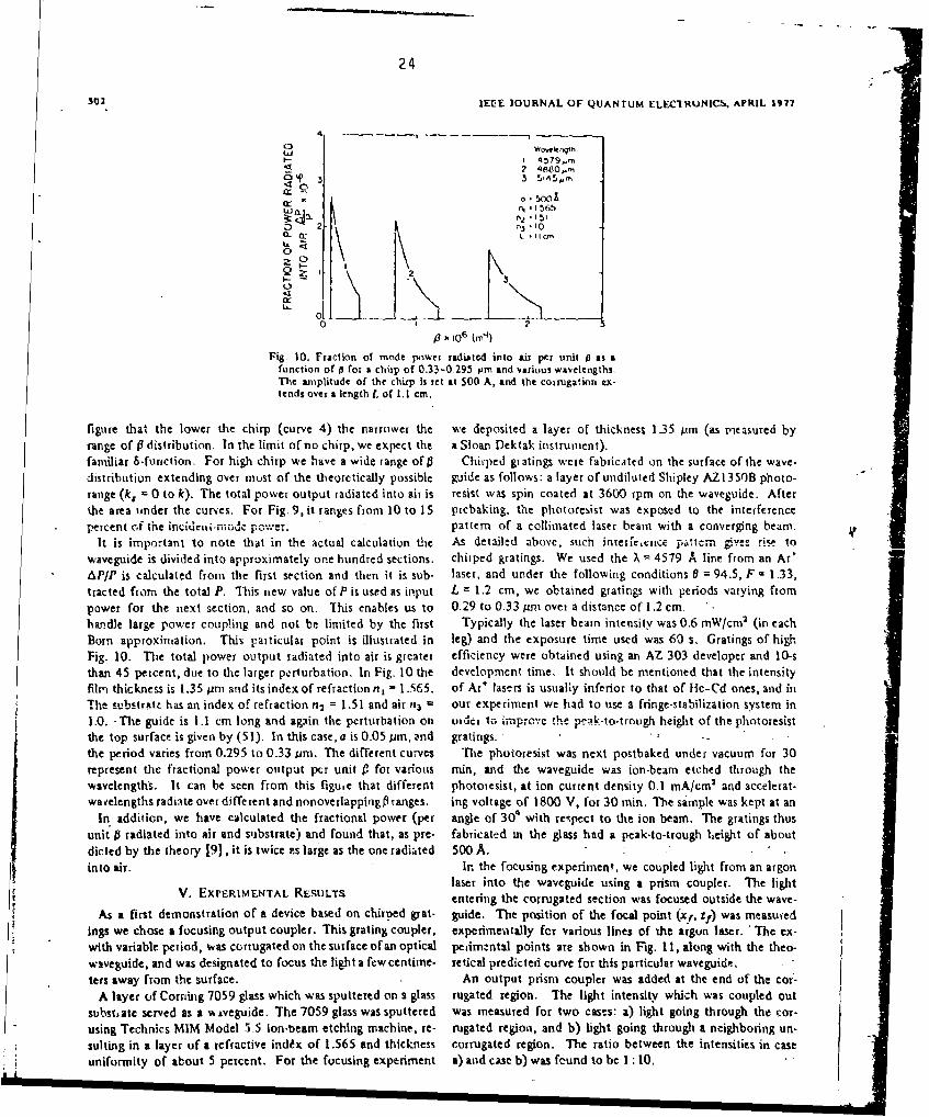
Fig. 10. Fraction of mode power radiated into air per unit C as afunction of 0 for a chirp of 0.33-0.295 prm and various waveltengths.The amplitude of the chirp is iet at 500 A, and the coirugation ex-tends over a length L of 1.1 cm.
figure that the lower the chirp (curve 4) the narrower the we deposited a layer of thickness 135 pim (as measured byrange of # distribution. In the limit of no chirp, we expect the a Sloan Dektak instrument).familiar 6-furnction. For high chirp we have a wide range of 0 Chirped gr atings were fabricated on the surface of the wave-distribution extending over must of the theorctically possible guide as follows: a layer of undiluted Shipley AZI350B photo-range (k, = 0 to k). The total power output radiated into air is resist was spin coated at 3600 rpm on the waveguide. Afterthe area under the curyes. For Fig. 9, it ranges from 10 to 15 prebaking, the photoresist was exposed to the interferencepercent of the incidcut-niode poweer. pattern of a collimated laser beam with a converging beam.
It is important to note that in the actual calculation thle As detailed above, such interfetcirc pattern gives ri- towaveguide is divided into approximately one hundred sections. chirped gratings. We used the X = 4579 A line from an ArtAP/P is calculated from the first section and then it is sub- laser, and under the following conditions 0 = 94.5, F a 1.33,tracted from the total P. This new value of P is used as input L = 1.2 cm, we obtained gratings with periods varying frompower for the next section, and so on. This enables us to 0.29 to 0.33 nim over a distance of 1.2 cm. ,.handle large power coupling and not be limited by the first Typically the laser beam intensity was 0.6 mW/cma (in eachBorn approximation. This particular point is illustrated in leg) and the exposure time used was 60 s. Gratings of highFig. 10. The total power output radiated into air is greater efficiency were obtained using an AZ 303 developer and 10-sthan 45 percent, due to the larger perturbation. In Fig. 10 the development time. It should be mentioned that the intensityfilm thickness is 1.35 tam and itsindex of refraction n, = 1.565. of Ar÷ lasers is usually inferior to that of fie-Cd ones, and inTh, substrate has an index of refraction n2 = 1.51 and air n3 = our experiment we had to use a fringe-stabilization system in
1.0. -The guide is 1.1 cm long and again the perturbation on utui 1o improve !he p-ak-to-trotgh height of the photoresistthe top surface is given by (51). In this case, a is 0.05 /m, and gratings. • I ..the period varies from 0.295 to 0.33 ,mn. The different curves The photoresist was next postbaked under vacuum for 30represent the fractional power output per unit P for various min, and the waveguide was ion-beam etched through thewavelengths. It can be seen from this figue that different photoresist, at ion current density 0.1 mAlcm' and accelerat-wavelengths radiate over different and nonovetlappingfl ranges. ing voltage of 1800 V, for 30 min. The sample was kept at an
In addition, we have calculated the fractional power (per angle of 300 with respect to the ion beam. The gratings thusunit 0 radiated into air and substrate) and found that, as pre- fabricated in the glass had a peak-to-trough height of aboutdicted by the theory [9), it is twice zs large as the one radiated 500 A.into air. In the focusing experiment, we coupled light from an argon
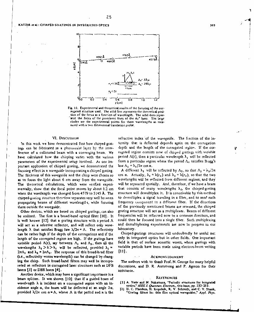
laser into the waveguide using a prism coupler. The lightV. EXPERtMENTAL. RESULTS entering the corrugated section was focused outside the wave-
As a first demonstration of a device based on chirned &rat- guide. The position of the focal point (xr,. z) was measu'edings we chose a focusing output coupler. This grating coupler, expcrimewitally for various lines of the argun laser. ' The ex-with variable period, was corrugated on the surface of an optical perimantal points are shown in Fig. 11, along with the theo-waveguide, and was designated to focus the light a fewcentime- retical predicted curve for this particular waveguide...ters away from the surface. An output prism coupler was added at the end of the cort-
A layer of Corning 7059 glass which was sputtered on a glass rugated region. The light intensity which was coupled outsubstate served as a %% Aveguide. The 7059 glass was sputtered was measured for two cases: a) light going through the cor-using Technics MIM Model 5.5 Ion-beam etching machine. re- rugated region, and b) light going through a neighboring un-suiting in a layer of a refractive index of 1.565 and thickness corrugated region. The ratio between the intensities in caseuniformity of about 5 percent. For the focusing experiment a) and case b) was found to be 1 : 10.L!
I1
25
KATZIR el al.: CFIRPEI GRATINGS IN INTEGRATED OPTICS 303
10 - -"-- - -T '
4965'651
4
2 5 A21-111 AL 295pI ICMI . ,,.51
-0 -- o-- ________* ' * "--" ,.--J*
6 2 04 06 0.8 '.0 5.2z (cm)
Fig. 11. Experimental and theoretical results of the focusing of the cor-rugate• structure used. The solid line represents the theoretical posi-tion of the focus as a function of wavelength, The solid dots repre-sent the focus of the prominent lines of the AT+ laser. The largecircles are the experimental points for these wavelengths as nita-sured vith a two-dimensional tianslation probe.
VI. DiscussIoN refractive index of the waveguide. The fraction of the in-" 'In this work we have demonstrated first how chirped grat- tensity that is deflected depends again on the corrugation
in, can be fabricated in a phoiovcsist layer by th i;nter. depth and the length of the corrugated region. If the coT-ference of a collimated beam with a converging beam. We tugated region consists now of chiipcd giating,; with vatiahlehave calculated how the chirping varies with the various period A(z), then a particular wavelength X, will be reflectedparameters of the experimental setup involved. As one im- from a particular region where the period A, satisfies Bragg'sportant application of chirped grating, we demonstrated the law A, = X,1/2n cos a.focusing effect in a waveguide incorporating a chirped grating. A different X2 will be reflected by A2 , so that A; = ; 2j2nThe thickness of this waveguide and the chirp were chosen so cos a. Actually, X, - X(zI) and ),a = X(z2), so that the twoas to focus the light about 6 cm away from the waveguide. wavelengths will be reflected from different regions, and theyThe theoretical calculations, which were verified experi- will be separated spatially. And, therefore, if we have a beammentally, show that the focal point moves by about 1.2 cm that consists of many wavelengths Xt, the chirped-gratingwhen the wavelength was changed from 4579 to 5145 A. The structure will demultiplex it. It is conceivable by this rrethodchirped-gr atirg stiucture the!etbre separates very well between to demultiplex a signal traveling in a fiber, and to send eachpropagating beams of different wavelengtl-s, while focusing frequency L.untsponcnt to a different fiber. If the directionsthem outside the waveguide. of the previously mentioned beams are reversed, the chirped
Other devices, which are based on chirped gratings, can also grating structure will act as a multiplexer. Beams of differentbe realized. The first is a broad-band optical filter 110]. It frequencies will be reflected now to a common direction, andis well known [123 that a grating structure with a period A could then be focused into a single fiber. Such multiplexingwill act as a selective reflector, and will reflect only wave. and demultiplexing experiments are now in progress in ourlength ), that satisfies Bragg law X12n - A. The reflectivity laboratory.can be rather high if the depth of the corrugations and if the Chirped-gratings structures will undoubtedly be useful no.length of the corrugated region are high. If the gratings have only in integrated optics but in other fields. One importantvariable period A(z), say between A, and A2 , then all the field is that of surface acoustic waves, whtre gratings withwavelengths X2 > X > X, will be reflected, provided Al = variable periods have been made using electron-beam writing2nA3 and X2 - 2nA2 . The response of this broad-band filter 1111.(i.e., reflectivity versus wavelength) can be changed by chang- ACKNOWLEDGMENTing the chirp. Such broad-band filters may wel be incorpo- The authors wish to thank Prof. N. George for many helpfulrated as reflectors in corrugated laser structuies such as DFB discussions, aid D. R. Armstrong and P. Agmion for theirlasers 131 or DBR lasers [41. assistance.
Another device, which may have a significant importance is abeam splitter. It was shown 1101 that if a guided bzam of REFERENCES
wavelength X is incident on a corrugated region with an in- I I A. Yativ and M. Nakamura, ".Periodic tructures for integratodoptics," IEEE . Quanrum. Electron., this issue, pp. 233-253.
idence angle a, the beam will be deflected at an angle 2ca, 121 D.C. Flanders, H. Kogelti, R. V. Schmidt, and C. V. Shank,provided X/2n cos a - A, where A is the period and n is the "Grating filters toy thin film optical waveguldes," Appl. Phys.

26 f "26 LEEE JOURNAL OF QUANTUM ELEICROMICS, APRIL 1971 -i
304
Lett.. vol. 24.p. 194. 1974. 48, p. 3187. 1969.
(31 K. A ,i , ef at., "GaAs-GaAIAs distributed feedback diode lavers lei -. 7Theory of Dielectric Optical Wavesuldes. Now York:
with Kepirati optical and canier conflncmcnt,"Appl. Phys. Lett., Academic, 1974.
voL 2 7,p. 145, 1975. [91 W. Strcltfr. R. D. BWt-nham, and D. R. Scifres, "Aimlys15 of
(41 W. Ng, H. W. Yen. A. Katvir, 1. Sam e., and A. Yarlv. "itoom grmtb.coupled r ldLatton In GaA t:GSAIAI Useru and wave-
temperature operstion of GaAs Bra" Mirror lasers." Appl. guides-1l: Blazing effects," IEEE J. Quantum Electron., vol.
Phys. Lert.,vol. 29.p. 684,1 9 7 6 . QE-12, p. 494.197
6 .
151 M. L. Dikus, L. Kuhn. P. F. Heidrich, and B. A. Scott. "Grating (101 H. Kogelnik., "Filter response ,f nonuniform almost-periodic.
coupler for eificient excitation of opical guided waves in thi structures," Bell Sysi. Tech. J., vol. 55, p. 109, 1976.
fllrm,"Appl. Phys. Lett., vol. 16, p. 523, 1970, [11( K. S. Pennligton and L. K uhn, "'Brig diffraction beam iplitter
161 It. A- Bartollr. "Chaxacterir•ic of relief phase hologpram to- for t hin flirn optical guided wev ea ." Opt. Commun., vol. 3, p.
corded in photoresatst," Appl Opt.. vol. 13. p..12 9 , 1974. 387. 1971.
•71 D. Marcuse, '•.ode converdon caused by surface imperfec- 1121 R. C. Williamson, "Psopertles and applictions of reflective-
tlons of a dielectric slab wavcgulde." Bell Syst. Tech I.. vul. array devices." Proc. IEEE, vol. 64, p. 702, 1976.
L I

27
Chirped-grating demultiplexers in dielectric waveguides*A. C. Livanos, A. Katzlr, A. Yarlv, and C. S. HongC'.cljfornia Institute qf Tecrhnolcily. Pa~adena, Cal~jbrnia 91125tkcivci' 17 Jhnua;r !97?; accet'M for rublication 14 March 1977) i
A wavelength -selctive bearnsj'liticr licki been irealied by febtics-ting chtirped (%ariable pciiod) Siating iii anoptical wavcjnide. This bemsnplitter can doniultiplex j% signial traveling in a fiber acid send each Fi'equrIcy
comixonent to a differtnt fiber.
PACS nunibers: 42.80 Hq, 42,80,Lt. 42.tO.Fc
We have recently described the fabrkc~ttion of chirped the wavelength X, falls withiln the "'forbidtivn' propagit-(variable period) gratings In dielectric wavegitides' tiori gap. It is thus at functiont of the chirp rate and thesuid have demounstrated the use of these ;,ratinigs in coupling constant, which in a giveni waveguide dependsfabricating focusing output couplers. 1 In thib work we on the corrugation height said profile.report the use of chirped gratings for the realization ofniultiple~xing or demuitiplexing dtevIces.
Consider a dielectric waveguide with a corrugated - --------
region of period A, and a guided optical beam of wave-length I~ incidrnt on the corrugated region at san angle ,
a Nee Fig. 1~a)]. Thto beam- will be dieflectoc:1 at anangle 2a, provided Bragg's law A=?X/2ptcosa is scatin- _ _ i ]tied. where n Is tam effective refractive index of the I 1wave,!ulde.
If the corrugated region consists of a grating with a (a)-variable period A(z), then it follows that diitfrent loca-1tionis In the corrugated waveguide will deflect different ' '
wave~lengths as shown in Fig. 1(b). A particular wave- 14 1length X, will be reflected front that part of the chirped/grating where the period A, asatisfies the condition 4 ~ 7A, - X/2ti cosac, while a (different) wavelongth Xj will A;<K'Ybe reflected from the portion of the grating where U.e ~period A, satisfies the condition A,-X3/2ttcnsa. Thievetwo wavelengthim, which initially occupy the same beam, YI]. 1. (a) 11vainoplitting in a dtilmnstriv wavogulde with m #>rn-are thus deinultiplexed, L e. , sep-Lrated spatially. The stant gratinig perlod A. Nh 11aiamaplitting and nwmltipllxtnj infiaction of the light of wavelength X, that io reflected a dielectric wavibguide with chirlied Ivarlable pecrtod Atm))depends on the length of the waveguide nection for which grating.
Sig Applied Physics Latters. Vol. 30, No. 10. 1t, May l197 big

28
To fabricate waveguides we used an ion-milling sys-team, and sputter delrosited a wav guiding layer of 7051wCorning glass on No. 3010 Clay-Adamis microscopekslides. The samples were cleaned according to theinuthod djescribed in Ref. 4, aad the back surface waspaiOnted flat black, A layer of AZ-135011 photoresistwas then deposited, and after 30 sec was spun at 3600rpmi for 30 sec. T1his was followeci by baking for 30min at 125 'I.
The chirped grating was recorded in the photoresistby eXp)OSing the latter to the interference pattern of acollimatecd lazier beam with a converging one, gencratedby a cylindricaLl lens. The chirping depends on theangle between the Illuminating beamns, the wavelength,the F number of the lens, and the position of the lenswith respect to the sample.'
* For this experiment we used an Ar* laser at the4579 -A line. T'he angle between the collimnated beam
* and the bisector of the converging bcara was 95%. The*F number of the lens was chosen to be 2. 66 and the Y60 X,~-(,70&
pattern was recorded over a distance of 9 to 14 mm.This arrangement resulted in a total period variationof 8 to 10% over the grating length. The samples were-exposed for 65 sec and the power per beam was 1. 2znW/cml. Subsequently they were developed for 10 secin AZ-303A developer and rinsed for 2 min in dvionizedWater. They were vacuum baked at 100 *C for 30 min,and then the chirped-grating pattern was transferred............-
expeimen reprtedherewe hve ued a of two different wiwvelengths from hvo diffe~rent locationsE in a _
singe nodewaveguide of thickness 0. 95 pm, as inea- h xmietsonnFg.2a.Tedhdlnsouiete
line, ad i wasdetrmied rom he iffac- period variation as a function of distance was mecasuredtinageof an exterinally incidrnt Ar' laser beam, as before and was found io vary from 2075 to 3360 A
Tepeak-to-troughhegtotecorgtosithovrtettlfnacof.9 i.Tsvrainws
launched the tunable output beami of a cw dye laser into used, the peak-to-trough heighi uI the grattng wasthe waveguide using a prism coupler, The angle a be- es;timated to be 400 A. The angle or between the inci-tween the propagating beam and the grating was adjust- dent beam and the grating was measured to be 50' * 1%.able, and was chosen to be approximately 48'. The dye laser was lumed from 6030 to 6300 A and the
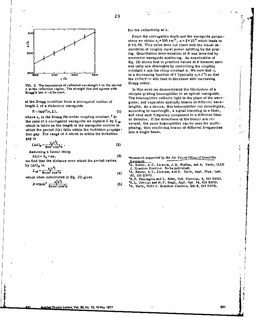
It was found that for yellow light, the light Is reflect- locations of the reflection of different wavelengths.4 from the left side of the chirped grating, and as the were determined by using a traveling telescope mountedwazvelengW. increases the reflected beanm moves to the on a translation stage. Since the period variation A its aright. The reflection at two distinct wavelengths 6070 function of r was already known, we could now corre-and 6270 A Is shown In Fig. 2(a). These beanms are late the wavelength X, and th~e period A, that causedseparated spatially by 4 mm. Figure 2(b) shows the reflection. The plot of X as iL function of A is shownt Lnoutline of the grating, as well as the positions of the Fig. 3refl~cted beams. The r hi linn plot of A versus Xi agrees with
To measure more quantitatively the t coordinate of Bragg's law A =A/2i mcoso. From the slope of the linethe location where reflection occurred as a function of and the measured incidence angle a -50' * V we cal-wavelength, r. second experiment was performed. culate ani effective Index of refraction n = 1. b ý 0. 1 InA 0.65-purn waveguide with surf;.ce uniformity better agreement with the value determined, Independently,than 5T was used. The effective Index of refractioit of by the prism coupling method.the waveguide was measured with conventional prism As a rough estimate of the reflection at a given wave -coupling methods imnd was found to be 1. 53:L0. 01. The length we use the expression for the power reflection
820 Appi. Phys. Lett.. Vol. 30, No. 10. 15 May 1977 LUvanos t a. '5W0
29
-, I b Ifor thie reflectivity at X.
From the corrugation depth and the waveguide param-
eters we obtain K, '100 cm"', a -• 2x 1O"- which leads toJR -0.50. This value does not clash with the visual ob-
servation ot roughly equal power splitting by the grat-•ooo " ing. Quaz,titative determination of R was thwarted by
excessive waveguide scattering. An examination ofEq. (4) shows that in practice values of R between zero
and unity are obtainable by controlling the couplirn;
constant K and the chirp constant a. We note that ,q6,00 6200 6•30 is a decreasing function of I (typically K, m 1-1) so that
. (Ai the reflectinn will tend to decrease with increasing
FIG. 3. T'e depedence of reflected wavelength ) on the period Bragg order.
A at the reflection region. The straight line plot a.rees with In this work we demonstrated Wte fabrication of aBrea's law A -, X/2n cosv.a chirped-grating beamsplitter In an optical waveguide.
The beamspiitter reflects light in the plane of the wave-at the Bragg condition from a corrugated section of guide, aind separates spatialy beams of differen:. wave-length L of a dielectric waveguide lengths. As a device, this beanisplitter cwn demultiplex,
R =t,•hb(,rL), (1) according to wavelength, a s*fjnal travelihg in a fiber,
where K, is the Bragg Ith-order coupling constant.$ In and send each frequency component to a different fiber
the case of a corrugated waveguide we replace L by L, 3 or detector. If the directions of the beanis are rr-
which Is taken as the length of the waveguide section In versed, the same beanisplitter can be used for multi-plexing, thus combining beams of different freq•uencies
which the period A(t) Calis within the forbidden piopaga - ale ingle beam.
tion gap. The range of A which is within the forbidden,
gap is
8un cos (2)
Assuming a linear chirp
A( )= -- 5 + ez, (3) ~*Research supported by the Air Force Offizc of Scientfieo
we find that the distance over which the period varies _ Rin ..-_ t
by (MA), is 'A. KLtzir, A...C. Lhvas, J.B. Shellan, and A. Yariv, IEEEL -- _ J. Q-uantum Eleýctron. (to be published).
BanI COO (4) A. Kattir, A.C. Ltvmuou, aL-d A. Yarlv, Appl. Phy@, Lett.8•an"Cos'( ($) 30, 225 (1977).
which when substituted in Eq. (1) gives K.0, Pe2•2•.Won and L. Kuhn, Opt. Conmsun. 3, 357 (1971).R t_.hl 4S. L. 11orinum and M.P. Singh. Appl. Op~t. 14. 818 UL975).ah'--1 ( A. Yariv, IEEr J. Quantum Electron. QE-9, 919 (1973).
A A a Ph, as Lners.u Vol. 30. No. 10. 15 Mby 1977 V1

305
Linearity and enhanced sensitivity of the Shipley AZ-i 350Bphotoresist
A. 0. Livanos, A. Katzir, J. B. Shellan, and A. Ytariv
The properties of the Shipley AZ. 135011 positive photoresist u~sed with tihe Shipley AZ 303A developer wereinvestigated. It was found that the use of AZ- 3013A developer re!ults in a significant irmprovenient of thetsensitivity and the linearity of tli phot iresist. 'lie unexposed etch rate of the photoresist was; 3S A * Sksec. Grutings of high efficiency ha~ve been successfully fobricatedi using the above cominiration of phoitores-ist and develuper.
Current work in integrated optics requires the fab- of etching of unexpose'd ones, and Ar C- r, -- r.2). If therication of relief grating structures on photoresist and term cE is much les;s than 1, Eq. (1) can be linearized asthe subsequent chemical ur ion beamn etching through follows:the photoresisi.? If the period of the grating is to 1-e less Ad -Ar7'cE 4 r2T. (2)than 0.4 pro the Shipley AZ-1350B photoresist is comn-monly used. The properties of this positive acting In this work we determinhed the pararneters involved* I photoresist have been examined in detail, 2 3 anod it. was in Eq. (2) for the Shipley AZ-1V350B photeresist usedP fund thnt th~e photoresi-f exhibits strong nonlinearity, with the AZ-303A developer,especially for etch depthrmmiging froin 0.05pmrto 0.2jm. T1he samples us-ed weic INO. .11010 nncriin.cupe zliffenBartolini'4 5 first showed that a differenit developer, made by Clay Adams, which, cut in half, resulted in a
namely Ithe AZ-303A, used with the old AZ-I 350 pho- size of 38 mm X 25 mmi X I mm. The samnples weretoresist (now replaced by the 13,5013) results in an cleaned according to the method presented in Ref. 8,Iunexposed resist etch rate of approximately 200 A/sec, and for some exilerimenis the back surface was paintedremove- the nonlinearity, and improves the sensitivity black with 3M Nextel 101-Clo velvet coating. Theby a factor of 2 or 3. Linearity and speed or sensitivity AZ-1350B photoresist was then deposited in a singleare always of practical interest.6 17 Norman and Singh 8 layer, anod after 30 sec it was spumn at 3600 rpm for 30 sec.have studied the characteristics of the AZ- I 350J resist The samples were baked, next, for 30 min at 100*C.(which has replaced the old AZ-1350H) Ldsed with the The first experiment involved the determination ofAZ-303A developer and report results similar to the the etcii rate of the uncxposed resist as a function ofones pmi esented in Ref. 5. It is the purpose of this paper development time for various solutions of AZ-103At'o show that the AZ-203A developer can be usýed withl d&v,-1pcr wvith distilled water. For this purpose thethe AZ-1350B photoresist resulting in improved sensi- samples were half immersed in the developer for the
ativity and linearity and unexposed resist etch rate of 35 required time, rinsed with deionized water for 2 min,,5, A/sec. and thei. baked under vacuum at 100'C for 30 min.
Bart~olini 5 hlas shown that for a positive acting pho- The step size was mneasured using a Sloan Dektat in-toresist the following relationship exists- between etch struinent, and the resuilts are shown in Fig. 1. The 4:1depth ad and exposure E (in units of energy per unit isolution (four parts distilled water, 1 part AZ-303Aarea); developer) gave unacceptasbly high etch rates, and the
AdT~ 1 -irrxp---E)],(1) 8:1 gave low and nonlinear ones. We chose the 6:1ad wT~r -r cx(-c~jdilution for all our experiments, since it exhibited a
where T is the development time in seconds, c is the linear behavior and an acceptable etch rate of r 2 -35
Pxposure constant characteristic of the phiotoresist, r, A ± 5 A/sec. The development time chosen for theis the raeof etching of exposed molecules, r2 is the rate subsequent experiment was 10 sec.
For comparison, we performed the same experimentusing the Shipley MF-312 developer. This developeris free from trace-metallic elements and is commonly
used in the fabrication of phot-oresist. gr-atings in semi -ft Te authors are vith California Institute of Technology, PaLsdCe. conductor substrates. Figure 2 shows the unexposedCe4lirornia 91125. etch rate as a function of development time in minutes
Raceived 27 Novembmer 1976. for the manufactuyer's recommended dilution of 1:1. In
June 1977 / Vol 16, No. 6 / APPLIED OPTIC-S 1633

3*1
0fVILON.R TLM('PERAIURf 25- Table 1. Une Kposed Etch Rate for AZ PhotoreistI andAZ-303AAZ-303A Developer
UJnexposed AZ-303APhotoresiSt etch rate dilution Rleference
E 0.2 - AZ-1 350 150 A /bee 4:1 ,tAI) replaced by
AZ-1350B 35 Al/see 6:1 This paperAZ-1 350H -
replaced byUtnAZA 3503 200 A /see 6:1 6
0 1o 20 50 40 :10 50DEVELOPME!t.M1 IME (%10)
Fig. 1. Etchl depths in proof tiot~xpose AZ-135513 photorrsit as afunction of developmeni time in Acoiids for various dilutions ratios this case r2 is -5 A I A/sec, which is a much lower etchofAZ-303A developer. Thestoreof thiecrve!;dettrnivines r2,,hich rate than the one for AZ-303A developer. If resist
foF the 6A1 dilution is 35 A * 5 A thickness is small, if long exposure times are acceptable,and if linearity is unimportant., this niay indeed be abetter choice.
The results for the different resists using the differentdilutions of t~he AZ-303A developer are given in Table
To demonstrate the thickness change as a functionof exposure time, the 0.4416 jum line of a H4e-Cd laser
D3 EVELOPLIR *IEMPERATURE 25-L was used to illuminate half of the sample. The back
MF jM-312 surface of the sample was coated with black paint toT avoid interference fringes. The intensity distribution
of te lacrwa etter than 5% across tile Surface Of thesam~ple. The photoresist was exposed for a given tiuzoe
and then developed 10 sec in the AZ-303A developer 6:1dilution. Figure 3 shows the thickness change as afunct ion of exposure energy. It can be clearly seen that
0 ------ the behavior of the photoresist in the important 0.1-2 4 6 b to 0.2-pm range is linear, In contrast, the MF'-312 devel-
DEVEOPMET I ME (in)oper gave very small thickness changes for the sameFii. 2. Etch deptY. in pro of enu-xpored AZ>136013 photoresirt asa range of exposures. In Order to verify that the stylusfunction ofedeveop~ment timie in mrinutes for MY-312 developer. Th of the instrument was not scratching the surface, the
1:1 dilution results in rl - 6A :k I A. same samples were aluminized and then tested.To demonstrate the feasibility of using AZ-1350B
photoresist. with the AZ-303A developer in making highefficiency gratings, the following exAperimen~t wveus per-formed. Photore~sist was spin-coated on samples at.3000 rpm, resulting in a resist t hickness of about 3.1 ;Am.
The gratings were generated by exposing the samplesto the sinusoidal intensity distribution produced by the
*A:.03(6t)interference pattkrn of two collimated Ar 4 laser beams.MVLPE1 IE0 The wavelength used was 0.4579 pm, the angle between
the beams 94.5", and the intensity per beam 0.60mW/era 2. The exposed samples wrere developed inAZ-303A developer, baked under vacuum, and the ef-ficiency of the gratings wau measured. Figure 4showsthe absolute eff iciency of the gratings as a function ofexposure for two different development times. It is
/ L clewr that high efficiency 23% resulted by developing the10t 2V 30 smlsfr10 sec. To verify the theoretically predicted
EXPOSURE E ("J/Crv~t) period and the peak to trough height, a scanning elec-
Fig. S. Thickness change ad in pino f A7-13,1,013 photorenist as tron microscope was tised. The period was measuredfunction of expoaure Z In mW/cm'. a-he circles represent the AZ- to be 0.31 urn, and the peak to trough htight was 0.28
303A developer, and th~e viquares represent the MF-312 claveloper. )AM.
11634 APPLIED OPTICS Vol. 16. No. 6 June 19??

T Rrhe authors thenk D. R. Armstrong for his valuableDEVELOPER TEMPERATURE 25*C technical as,;istance. This research was supported byA Z- 303A
the U.S. Air Force Office of Scientific Research. The0t- wor onj.B. Shellan is supported-in partU by t- e Hertz(1_0 Is".) Foundation.
1: 0
0 20 40 WO 60 eO0 M O0
EXPOSURE E (mJ/cmtl
4. Grating efficiency (absolute) asa function of exp.sure E inV/cml for 10-sec and 20-sec development timnes in AZ-303A de-
veloper. Initial resist thick ness was 0.31 AM. R e
1. H. L. Garvin. E. Garmire, S. Somekh. H. Stoll, and A. Yariv, Appi.Opt. 12.45S (1973).
2. S. Austin and F. T. Stone, Appl. Opt. IS. 1071 (1976).
In conclusion, we have found that the use of AZ-303A 3. S. Austin end F. T. Store, Appl. Opt. 15. 2126 (1976).
veloper with the AZ-1350B photoresist results in an 4. R. A. Bartolini. Appl. Opt. I1, 1275 (1972).
Inexposed etch rate of-35 Al/sec and significantly in- .R. A. Bartolini, Appi. Opt. IS, 129 (1974).
reases the sensitivity and linearity of the photoresist 7. F. J. Loprest and E. A. Fitzgerald. Photogr1 Sci. Eng. 15, 260
Sthe 0.05-0.2-Mm range. We ht ve successfully made (1971).,ratings with constant and variable period9 usir.g this 8. s. L. Nurman and M. P. Singh, Appl. Opt. 14,818 (1975).
riethod and have transferred thern to glass using ion 9. A. C. Livanos, A. Katzir, end A. Yariv, Opt, Commun. 20, 179
Deam etching techniques. (1977).
/veo~e 7.F.JLopestendE. . Ftzgral, Potur. d. •

33
Broad-band grating filters for thin-film optical waveguidese)C. S. Hong, J. B. Shellan,b) A. C. Livanosc) A. Yariv, and A. KatArd)California Iratitute of Techrolog, Pasadeno. California 91125(Received 16 May 1977; acccpted for publicaktitn 1I ;unc "97-,,
Broad-band grating filters have biet, fabricated on gIlas thin-film waveguidcs and cvalutled with a tunabledye laser. Measured and calculated filter responses were found to be in good agreement. Grating filteriwith bandwidths of 300 and 150 A. and reflectivitics of 18 and 40%, iesp1ctivcl), arc reported.
PACS nuebc,: 42.80 Cj. 42,90.Lt, 47..0.Fn, 42 .61 .+n
Gratings on the surfaces of thin-film optical wave- Consider a thin-film waveguide supporting only the
guides have been used in -A variety of applications such fundamental mode. A surface corrugation gratbig with
as couplers,' beam splitters,t and filters"' in integrat- a period equal to half the wavelength of the guided mode
ed optics. The grating with nonuniform period (chirped will cause the normally incident mode to underg- re-
gratLng) has been the subject of current theoretical in- troreflection.3 The analysis of this problem uses the
terest. 5,6 Recently chirped gratings fabricated on thin- coupled-mode theory.'• In a chirped grating whose
film waveguides as output couplers' and wavelength period A varies as
demultiplexersa have been demonstrated. 2n/A(z)=2i/A(0)-2yz, 0<e<L, (1)
In this work we report the use of chirped gratings thV cUoupied-!nude equations become
for the realization of broad-band optical filters in dAthin-film waveguldes. Chirped grating corrugations - - iA = - iKB etxp(iyl), (2a)
were fabricated on sputtered glass waveguides using the dz
procedure described in Ref. 7. A tunable dye laser was dB .+ OB = iKA exp(- ivel). (2b)used to measure the wavelength dependence of the -b
filters' reflectivities. Bandwidths of 300 and 15G A and A and B are the compiex amplitudes of the incident andreflectivities of 18 and 40%, respectively, were reflected modes under consideration. K Is the coupling
achieved. These values were In agreement with calcula- coefficient, which depends on the profile and the depthtions based on measured waveguide and gratingparameters.
'OWork supported by the National Science Foundation f3ptical .,r,
CCommunication Program) aMm the Air Force Off ce of Si6-
al)ptnm1. and )ohn Hertz Foundation Doctcral Fellow. -0 AU-
OPresent address: Hughes Research Laboratories, Malibu, ECalif. 90265.
"4IPresent address: Physics Dept., Tel Aviv University, Tel "v
Aviv, Israel. FIG. 1. Schematic of 0ltar evaluation setup.
270 Applied Physics Letters, Vol. 31, No. 4, 15 August 1977 276
---.--..-

34loss constantL. 1 Imposing the boundary condition B3(L)=0, the solution of Eq. ,2b) using the approximationdes:rioed above is
n,, 1-) if K(Z)exp(-i?.,')expi2i( - lic)P.)az. (5)
tj•t 4+1 ICarrying out the integration leads to a reflectivity
-1 1I _- )-3 Ti (1' ((•)1 (),/>.] exp(- 2OZ,) if 0< Z <Lbj1. 0 otherwise. (6)
In the experiment a glass waveguide was fabricated bysputter deposition of a layer of Corning 7059 glass ona glass substrate. A Shipley AZ-1350B photoresist filmwas spin coated on the waveguide. The chirped gratingwas recorded In the photoresist film by exposing thephotoresist film to the pattern produced by the inter-ference of a collimated laser beam and a cylindrically
_. _ focused beam derived from the same laser. T Ar Ar*•.,., A) laser line at 457/9 At was used. The exposure of the
FIG. 2. Reflectv,ty versos wavelength for three grating fil- photoresist film took place inside a xylene bath, thuster@. 0 represertz filter l. 0 rejresents fliter 2. A narrow- reducing the laser vacuum wavelength by 1. 51, theband filter (Oilte: 3) to also shown and detailed in the Inset. index of refraction of xylene. Periods of -1950 A were
thus obtained. The F number of the cylindrical lens waschosen so that it resulted in a desired period variation
of the grating corrugation. 6 is a phase mismatch factor over the grating surface whose length was 10 mam. Theand is defined by photoresist grating was then transferred to the wave-
6 = w/A(0) - (3) guide surface by ion -beam etching. To evaluate thechirped grating filters, the output beam from a tunable
where P is the propagation constant of the uncorrugated dye laser (linewidth -0.5 A) was launched into thewavegulde mode, The point where the Bragg resonance waveguide by r prism coupler. This prism coupler alsocuntiti. o --,2/,: -2 •-= 0 is satiLfied 0hart be referred served as the output coupler for the reflected waveguidetc as the Bragg point, za = 6/1. Equations (2a) and (2b) niode. The incident and reflected waves were separa-edcan be combined to give second-order differential by a beam splitter, and their relative power ratio wasequaticons for the incident wave A and the reflected wave measured. The experimental setup is sketched in Fig.F. The solutions of these eqoations are the parabolic 1. In a chirped grating different wavelengths are re-cylinder functions. 10 By matching the boundary condi- flected at different points along the grating. The lighttions fox A and B and using the asymptotic expansions is launched into the short period end of the grating sofo.e the parabolic cylinder fnctlons, we obtain the ex- as to minimize losses due to coupling ir,to substratepression f,,.- reflectivity radiation modes. As a result, longer wavelengths
R = I -exp(- v K1/). (4) penetrate further into the grating and thus undergo alarger attenuation due to the residual waveguide loss.
This asymptotic expansion is good for cases when the This loss a was determined and the observed reflec-Bragg point is far from the grating edges, i.e., 5K/V Uvity at X was multiplied by the factor expl2ozt()] to<'t1 <L - bK/Y. It lowever, for large chirps the incident obtain the inir, siL, 1ilter ,., .... "ty. The ... _-,-r-
mo'ya is coupled into the reflected mode only over a rected spectral responses for two grating filters withportion of the grating length, and the resulting reflec- different chirp factors are shown in Fig. 2. Also showntion may be small. Under these conditions we may set in Fig. 2 for comparison is the response of a uniform-B-=-0 in Eq. (2a), solve for A, and use this approximate period grating filter (I mm long) whose band-limitedsolt."cn of A In Eq. (2b) to solve for the reflected wave characteristics is presented in the inset. The ability toB. We account for residual waveguide losses by replac- tailor-design the bandwidth of an optical filter Is thusing 6 everywhere by 8 4 •ir, where a is the (intensity) manifest,
TABLE I. Summary of data obtained from three grating fliters.
Effective IndexPeriod Length Corragation Wavegulde of refraction Wavelength(A) WL) depth (W) thickness (0 at X-Z950 • response Bandwidth Renectivtx
Filter 1 Chirped 1905--2005A 10 mm 350 A 0.777 pro 1.524 5810-610 A 3oo A 18%
Filter2 Chtrped 1925-1975 A 10 mm 400C 0.85 Jon 1.524 5870-6020 X 150A 40%
Filter 3 Uniform 1955 A 1 imm 250 X 0. O0 pm 1.519 5946 A 4 A 80%period
a 1~. 51. nf-1.5M, %--1.
277 Appl. Phys. Latt., Vol. 31. No. 4, 15 August 1977 Hongretd. 277
z9

The measured parameters of the three filters are IM.L. Dikss. L. Kuhn, P.F. Heidrich, and B.A. Su.tt., Appi.* su.-niarized in Table I. The bandwidths are In good Phya. Lett. 16, 523 (1970).
wK.S. Pennington and L. Kuhn, Opt. Commun. 3. 357 (1971).agreement with the design values, while the measuied 3Hi. Stoll and A. Yartv, Opt. Commun. 5, 5 (1973).and calculated values of reflectivity are within 109C. D.C. Flandora, H. Kogelnik, R.V. Schmidt, and C.V.
Sh:%nk. Appl. Phys. Lett. 24, 194 (1974).6H. Kogelnrt, Bell Syst. Tech. J. 55, 109 (1976).
In conclusion, we have demonstrated the fabrication 4M. Msta.hara, K.O. H1ll, and A. Watanabe, J. Opt. Soc.of chirped grating filters in thin-film optical wave- Am. 65, 804 (1975).guides, The control of the wavegulde, corrugation, and IA. Katzir. A.C. Livanos, J.3. Shellan, and A, Yariv. WEE
chirp parameters leads to band rejection filters whose 3. Quantum Eletron. QE-13, 296 (1977).conforms closely to design values. A.C Livanos, A. Katzir, A.Yariv, and C.S. Hong, Appl.
response cPhys. Lett. 30. 519 U977).$A. Yariv, IEEE J. Quantum Electron, QE-9, 919 (1973).
11R.B. Smith, J, Opt. Soc. Am. 60, 882 (1976).The authors wish to acknowledge the assistance of IIA. Yariv. Quantum Electronics, 2nd ed. (Wiley, New York,
D.R. Armstrong. 1975), p. 52o.
I
eV
• )•e= =.•il -u, ,:ls Letes VoiW. 31, No. 4. t5 Auguti 197 27

36 O"
I
I I
Simultaneous exposure and development exposure to light can be described by2-3
of photoresist materials: 0AIl(t) ,Mt(x.t) I(X.t)
an analytical model 6t h" *1P. Agmon, A. C. Livanos, A. Katzir, and A. Yariv where
When this work was done all authors were with CaliforniaInstitute of Technology, Pasadena, California 9,125: A. C. M - inhibitor coh hotration (cn-l),Livanos is now with Hughes Research Laboratories, Mali- lighiniensity, .ection oi b roelSbu, California 90265 and A, Katzir is with Tel Aviv Uni- l - quantu efiienciy,
verrity, Physics Department, Tel Aviv, Israel. quantum efficiency,Received 13 ,june 1977. a - absorption cross section of inhibitor moleculesPositive photoresist plays an important role in fabricating v - light frequency (sec-1).
a variety of devices, including diffraction gratings. Theconventional rnethod for making such gratings is to expose the Equation (1) can be rewritten
photoresist to the interference pattern of two collimated laser aM(x.t) M ,t)beams, and then in a separate step to develop it Tsang andWang' proposed a new technique in which they exposed and
developed the photoresist simultaneously. We shall refer to where the decompositior time r is defined as
this technique as the SED (simultaneous exposure and de- (velopment). This technique enabled them to reduce the ex- [(X~t)]posure time and hence increase the SNR of the image in sit-uations requiring large exposures. In addition they succeeded r is an important parametei: It contains the interaction be.
in producing gratings of deep grooves and narrow lines. In tween the light and the photoresist.what follows, a simple analytic model for the SED method is If we keep the source intensity constant and aM(x,O)f <<
described. The theoretical calculations are compared with 1, where ( is the film thickness, we may take Ix,t) = 1o In
experimental data. this case i is independent of x and t, and Eq. (2) is easily
Positive photoresist materials are composed of two major solved. If the exposure starts at t - 0, then at t - T
components: a base resin and a light-sensitive inhibitor M(x,T) - M(x,O) exp(-T/r) (4)compound. Photodecompos;tion of the inhibitor moleculesduring the exposure decreases its concentration and, as a In the conveDtional method during the development step,consequence, increases the etching rate during develop- which follows the exposure, the photoresiat is being etched atmenrt a rate which depends on the loca inhibitor concentration. If
The rate at which the inhibitor concentiation is reduced by the etching rate of unexposed photoresist is r2(Am-sec- 1) and
2612 APPLIED OPTICS / Vol. 16. No. 10 / Occtober 1977

- 37
that of fully bleached is r, (pi n-ect I), the deveelopmnent pro-12cess can be modeled by
dx a ,-Ar xT) 5)Owe4
d - A .M.0') is)where Ar - r, - r2 and T -the exposure time, Int the ap- 003proxiniation of Ax,t) -Jo. Eq. (5) becomnes
L)- i,- Ar exp(--T/v)jD. (6) 3
where LD is the thickness of the photoresist layer removedduring development time D. 000
In the SED technique a substrate coated with positive s. 2 ' 5 Zphotoresist is immtersed in the deveboper while exposed. As a
aresult, the photoresist is exposed and etched simulta-05
Following Eq. (5), the etching rst~e during SED is givenby 03.8'
which, for the approximation I(x,t) !!!e I, becomesdx Oi-lrep -t )-(8 1
If SED is started at 1 0, then at It S the thickness of thephotoresist layer which has been removed is d
Ls - riS - areill - exp(-S/fdJ. (9) Mb
If after following the SED step the exposure is turned off and Fig. 1. Difference in etched depth bet ween exposed and unexpoarthe photoresist remains in the devteloper for a time D (i.e., Shipley AZ-13,OJ photoresist in AZ-M0A developer: (a)for varyingcinventions! develonment), using Eq. (6), the thickness of the SEt) time followed by constant conventional dev eloping time (Dremoved layer is r )rc): (h aor SE time. (S - I~ nser) followed by varying
conventional dwevelping time. The solid lines lite calculatz~d usingLr Ls + LD w r1S + r2D -+ Arli1 - e~p(-S/r)l (D - Y). (10) Eq. (12 wih - Sir d -DIF, T- .47.7 see, 1. - .3 m'sN'/cm2 Ar
The difference in height bet weeen the exposed and the unex- 0.1 pm/isec.posed areas is is
aL - L7 - r2( Vq- D) -ArIS + (D - i)JI - exp(--s/r)]l. (11) 0.1 Mm/se,:. These values fit our mecasuremnents. within theexperimental error, and rno effort was made to measure them
Defining s & Sir. d v Dir, Al a A.LIArr, directly.
Al - s + (d - 1)[I - es(xI.(12) The theoretical model and experimental data are comparedin Fig. 1.
Equation (12) describes the SED process and a following In Fig. 1 (a) the SED durationi is varied, while the conven-conventional development, independently of light intensity tic,nR' developing timne is constant and sirall (5 sec, the timeand dce'elcpirmg parameters. provided Eq. (8) is valid. required tW remove the sample from the liquid gate and rinse
To compare the theory with experimental data, Shipiey it in diu iili d. wnlr). Thit cAce is the most important one1360J positive photoresist in AZ-303A developer" was chosen. hvoa-;sqe it represents the regulitr use of SEt). It is to benotedEarlier work by Bartolini2 -uggested that this photore--ist-- that here the agtt ernient between theory and experimentaldeveloper system satisfied Eq. (6) (for conventional exposure data is good even when th.Ž removed layer is quite thick (forand development). A glass substrate coated with Shipley instance, the experimental point for s -1.4, (T 37.7 sec, S135WJ positive pliotoresist was immersed in AZ- 303A devel- - r 52.8 sec) corresponds to AL - 2 .8Mum or t~otatl etchedoper, contained in a rectangular liquid gate with walls mnade depth of LT 3.7jum, using2 r2 =0.015 gm/sec). In Fig. 1(b)of optically flat glass. The exposed region of the photoresist the duration of the SEt) is constanit and sinall while the fol-was uniformly iluminated by a 4579 - A argon laser beam. lowing conventional developing time is varied. As expected,The photoresist film thickness was initially 5.0 Jim. To since the theoretical model does not take into account thecompare experimental data with Eqs- 011) and (12) the plate nonuniform distribution of the light intensity throughwas partialy covered, such that only half of it was exposed to thickness of the photoresist, the theoretical prediction doesthe laser light, whitle the whole plate (including the unexposed not agree with the experimental points when the developmenthalf) was immersed in the developer. As the plate was aillu- time is long (thick photoresist layer).niinsted, the exposed half was simnultaneously exposed and The exposure energy and the etching rate as a function ofdeveloped, while the cove 'red half was developed only. The depth cma be calculated.thickness difference between the two halves was measured Consider a layer at depth x which is removed at 9 - S(x).using a Sloan De~ktalc instrument. The intensity used in the The exposure energy at that depth isexperiments was '-5.3 mW/cm2 (on the photoresist) surface). Sx.The developer was diluted in a 1:6 ratio.5 E(x) X Cieýj) dt m I, S(z). (13)
For the theoretical calculations the values of ip, a, and Ar-'are needed. Broycles has found ig 3.2% and o -659 X Define e(x) a E(x)/J,,T and 4 a x/ArT. Equation (13) be-10-1 1cm 2 (measured at 3654 A.BartolIini 2 has found Ar comes
Octocer 1977 / Vol. 16. No. 10 / APPLIED OPTIS 2613

-38 "
,So 50 smaller the exposure eneqgy and, hence, the smallei theetching rate.
L, dIIt is interesting, and important, to note that while ir. theconvcntional method the difference in etched depth between
D5 ,5 the exposed and unexposed photoresist is linear with the ex-posure time (and energy) for T/r < 1 [sec eq. (6)], in the SEDSmethod it is linear with SED time for (S/,) > 1.
In conclusion, a simple analytic model was applied to the(01 0simultaneous exposure and development of positive photo-00ooo 0 re3ist. The model has been corifirmed to be in good agree-
S'ment with experiment under the following conditions.1. Shipley 1350J positive photoresist in AZ-303A devel-
Fig. 2. Notrmalized etching rate [l/&,r/(dx/dt)l and exposure oper.energy (i - E10r) as a function of depth (usingl ri/Ar - 1.15). 2. up to 5;m thickness if photoresist,
3. uniform illumination, andQ() Q(s). (14) 4. short conventional developing time.
The validity of the model, for other types of photoresist/From Eq. (9), developer systems, is under investigation: In addition, its
application to grating fabrication is studied.A - l - I - ezp-dO)9. (15) The authors tbank D. R. Armstrong for his assistance. This
From Eq. (15) the exposure energy as a function of depth can work was supported by the National Science Foundation, bybe found. Once t(Q) is known, it can be used, together with the Office of Naval Research, and by the Air Force Office ofEq. (14) and Eq. (8) to calculate the etching rate (dxldt) as Scientific Research,a function of depth.
The normalized exposure energy [de,)] and etching rate ReferencesF dz " 1. W. T. Tsang and S. Wang, App. Phys. t.ett. 24,196 (1974).S- (•) I2. R. A. Bartolini. Appl. Opt. 13, 129 (1974).Ar dt 3. F. H Dill, W. P. Hornberger, P. . Hauge, and J. M. Shaw, IEEE
are plotted in Fig 2. Trans. Flectron Devices El)-??, 445 Z 975).As is expected, in the SED process, both the exposure en- 4. Shipley Company, Newton. Mas%. 0t62.
e."1' and the etching-rate increase with depth, since each layer 5. A. C. Livanos, A. Katzir, J. B. Shellan, and A. Yariv, AppL. Opt. 16,is exposed to radiation until it is etched. This Is in contnast !633 11^77).to the conventional method, where the deeper tht layer the 6. B. Broyde, J. Electrocheme. Soc. 117, 155b (1970).
S 2614, APPLIED OPTICS/ Vol. 16. No. 10 ]October 1977I I I I I III I

39
4. Personnel Supported under the Subject Contract
4.1 Professional Staff
Dr. Nicholas George, Principal Investigator
Dr. Alexander C.R. Livanos, Research Fellow
Mr. G.M. Morris, Graduate Student
Mr. M. Abushagur, Graduate Student
Mr. H, Parker, Graduate Student
Mr. M.J. Kavaya, Graduate Student
4.2 Technician and Underurduates
Mr. Joshua Rothenberg, Undergraduate
Mr. Everett Coffelt, Senior Technician
'II

Sli 1U I I IN I L A, .J . , A -t A.
REPORT DOCUMENTATiON PAGE REAL) INSTRUC[IONS
I UFFORE C-oNPLETING FORMI.RLPORT NUMBER . GOV-T ACCZSS~IOt NO. 3. RECIPIENT'S CATALOG NUMBER
TITLE (a.ld 511hlltI..) 5 TYPE OR: RLPORT 6 PLR.Un COVERED
OPTICAL DATA PROCESSING AND STATISTICAL. OPTI ~ FINAL
6. PERFORMING ORG. REPORT NUMBER
7. AUTHCOR(.) - CONTRACT OR GRANT NUMBER(A)
N. GLORGýI
9. PERPORM!NG ORGANIZATION NjAMF AND AIOORESS 10. PROGRAMI CLEMENT. PROJECT-. TASKAREA & WORK UNIT NUMBERS
Cal ifor~iih Ifls'i~tlte of TechnologyPasader-a CA 91125 61 102F 230551
11. CONTROLLING OF:FICE NAME AND ADDRESS 12. REPORT DATE
AFOSR/NE Oct 78Bollinj 13 C203 o NUMBER GF PA\GES
14 MONITOlING( AGENCfY'N AME & ADDRESS(If dillereIII 11-n,1 Cpo.I 111,2I~~ Mille) 15. SECURITY CLASS. (of thia leprOfI
I UNCLASSIFIEDIa ECL ASSI FICATION'DOWNGRAOING
SCHEDULE
16 DISTRIBUTION ST ATEMENT (-f hit Rqporl)
* Approved for public release; distribut-ion unlimi~ted.
I? UST IUTION 51 'LN T (~I abt1ractI ~oritood inl Block 30. 1i different frotHil, I r"1)
Id SUPPLEMENTARY TLS
19- KEY KOOS 1Ct.~flinu m. t0o'Crse a8II it w~llV in denti~fy by bhwk~ I,i,nl~b~rr
2Z, AB~zT RAC7T (C.I, o -1111- " roe S ide if rI1..*.OT) ad idenilty by block - b )
Research on the. fabriCat Ori of grat ing structures for Uwe iii integrated opticsit, desCi ibed. Chiirped or variable period gratings have been successful ly made
by a holographic piuccess. Briefly, a waveguiding layer of Corning 7059 qI"issis sputtered onto a subst~rate gilass using the Technics MIM Model 5.5 ion beamVtChin mc lachin e. P~hutores is t is coated oni t the weveguiding aycr . exposedhol Ographiicall1y in an argon or helikimu~-Cadlit Ur laser beam, developed and theni on-mi I led. Extcns yve theory and technique are reported in the b ib. iography ofpuhi ;-cations l isted in thi s report.
DD , MA 1473 UNCLASS IFrIED ______
4ECURITY CLASSFICATION OF THIS PAGE (R4hen Dare nFsritwirie,