Embed Size (px)
Citation preview


Train Derailment at Hatfield: A Final Report by the Independent Investigation Board
OFFICE of RAIL REGULATION • July 2006
Contents
Foreword...............................................................................................................1
Executive Summary.............................................................................................3
1. Introduction and Background.......................................................................7
The derailment.................................................................................................7
Cooperation during a fatal accident investigation ............................................7
The Independent Investigation Board..............................................................9
Roles and Relationships of the Main Duty Holders........................................10
Legal Obligations...........................................................................................12
Railtrack’s Safety Case (RSC).......................................................................14
Railway Standards.........................................................................................15
Rolling Contact Fatigue (RCF) and Gauge Corner Cracking (GCC): Industry’s Knowledge.....................................................................................................16
2. The Derailment.............................................................................................19
The Event ......................................................................................................19
The Rolling Stock ..........................................................................................20
The configuration of the vehicles where they came to rest............................22
Sequence of events.......................................................................................24
Key Features of the derailment......................................................................27
Actions following the Derailment....................................................................27
3. The Site Investigation..................................................................................31
Management of the Site ................................................................................31
Management of the Services of Experts........................................................32
Recovery of Evidence....................................................................................33
Safe Systems of Work and Restoration of Services ......................................35
Lessons Learned from the Site Investigation and Recovery Process............36
4. A Summary of the Technical Investigation – Rolling Stock.....................39
The technical investigation remit ...................................................................39
Post Crash Condition.....................................................................................40
Interpretation of Findings...............................................................................45
External Rail Factors .....................................................................................49
Main Findings – Rolling Stock .......................................................................50
Train Derailment at Hatfield: A Final Report by the Independent Investigation Board
OFFICE of RAIL REGULATION • July 2006 3
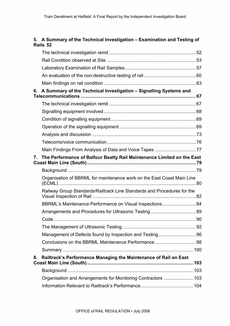
5. A Summary of the Technical Investigation – Examination and Testing of Rails 52
The technical investigation remit ...................................................................52
Rail Condition observed at Site .....................................................................53
Laboratory Examination of Rail Samples.......................................................57
An evaluation of the non-destructive testing of rail ........................................60
Main findings on rail condition .......................................................................63
6. A Summary of the Technical Investigation – Signalling Systems and Telecommunications .........................................................................................67
The technical investigation remit ...................................................................67
Signalling equipment involved .......................................................................68
Condition of signalling equipment..................................................................69
Operation of the signalling equipment ...........................................................69
Analysis and discussion ................................................................................73
Telecoms/voice communication.....................................................................76
Main Findings From Analysis of Data and Voice Tapes ................................77
7. The Performance of Balfour Beatty Rail Maintenance Limited on the East Coast Main Line (South) ....................................................................................79
Background ...................................................................................................79
Organisation of BBRML for maintenance work on the East Coast Main Line (ECML). .........................................................................................................80
Railway Group Standards/Railtrack Line Standards and Procedures for the Visual Inspection of Rail ................................................................................82
BBRML’s Maintenance Performance on Visual Inspections..........................84
Arrangements and Procedures for Ultrasonic Testing ...................................89
Code..............................................................................................................90
The Management of Ultrasonic Testing.........................................................92
Management of Defects found by Inspection and Testing.............................96
Conclusions on the BBRML Maintenance Performance................................98
Summary .....................................................................................................100
8. Railtrack’s Performance Managing the Maintenance of Rail on East Coast Main Line (South) ..................................................................................103
Background .................................................................................................103
Organisation and Arrangements for Monitoring Contractors .......................103
Information Relevant to Railtrack’s Performance.........................................104

Train Derailment at Hatfield: A Final Report by the Independent Investigation Board
OFFICE of RAIL REGULATION • July 20064
Railtrack’s Awareness of BBRML Failings...................................................106
Railtrack’s Performance – Management of Backlog of Defects ...................110
Railtrack’s Performance – Use of Audits .....................................................111
Rail Grinding................................................................................................120
Railtrack Performance – Underlying Causes...............................................123
9. Legal Proceedings.....................................................................................125
Background .................................................................................................125
The charges.................................................................................................125
The Court proceedings ................................................................................126
Fines against Balfour Beatty and Network Rail............................................126
10. HSE’s Prior Role Inquiry ...........................................................................127
Background .................................................................................................127
The PRI Recommendations ........................................................................128
Action Taken................................................................................................128
11. The Board’s Observations ........................................................................133
Key changes................................................................................................133
Changes to Railway legislation since October 2000....................................135
Strategies for improving health and safety on the railway ...........................136
The Rail Accident Investigation Branch (RAIB) ...........................................138
Conclusion...................................................................................................139
Appendices
Appendix 1 List of Figures
Appendix 2 Plan of Hatfield Rail Incident
Appendix 3 The Location of Major Features and Items Through The Site
Appendix 4 Hatfield Derailment - Chronology of Events
Appendix 5 Review of Site Investigation and Recovery Process: Recommendations
Appendix 6 Hatfield Derailment Implementation of the Board’s Recommendations – June 2006
Appendix 7 Explanatory Note of the Signalling System
Appendix 8 The Overall Structure of the Signalling System for the Hatfield Area
Appendix 9 BBRML Structure, Positions and Responsibilities
Appendix 10 Railtrack Structure, Positions and Responsibilities

Train Derailment at Hatfield: A Final Report by the Independent Investigation Board
OFFICE of RAIL REGULATION• July 2006 1
Foreword
At 12.23 on Tuesday 17 October 2000, train ID38 travelling from London Kings
Cross to Leeds derailed roughly 0.5 miles (0.8km) south of Hatfield Station. The
train, operated by Great North Eastern Railway (GNER), was carrying one hundred
and seventy passengers and twelve GNER staff. Four passengers were killed and
over seventy people were injured, four seriously, including two of the GNER staff.
This is the final report by an Investigation Board set up in response to a Direction
from the Health and Safety Commission (HSC) under Section 14(2)(a) of the Health
and Safety at Work Act 1974 (HSWA). The Direction required the Health and Safety
Executive (HSE) to undertake an investigation into the train derailment at Hatfield.
HSE’s investigation was carried out under the supervision of an independent
Investigation Board, operating in accordance with HSE’s Major Incident Investigation
Policy and Procedures.
The Work-Related Deaths Protocol for Liaison sets out the principles for effective
liaison between the organisations responsible for investigating work-related deaths in
England and Wales. In accordance with this Protocol the British Transport Police
(BTP) took the lead in this investigation because the offences under consideration
included manslaughter. BTP remained in the lead throughout the investigation.
The HSE Investigation Board oversaw only the HSE aspects of the investigation and
had no locus over BTP’s investigation. Sandra Caldwell (currently Director of HSE's
Field Operations Directorate) chaired the Investigation Board.
HSE has published two interim reports, one on 20 October 2000 and the other on 23
January 2001. The Investigation Board published its interim recommendations in
August 2002 to highlight remedial action identified from the investigation, and to
share this with the railway industry. A final report from the Investigation Board can
only be published once all legal proceedings and any subsequent appeals have
concluded.
On 15 July 2004 the Secretary of State for Transport published a White Paper ‘The
Future of Rail’ setting out the outcomes from the Rail Review he announced in
January 2004. He decided that the regulatory responsibility for health and safety on
the railways should be merged with the Office of Rail Regulation (ORR) to create a
new body. This transfer of responsibility was given effect from 1 April 2006 through
Train Derailment at Hatfield: A Final Report by the Independent Investigation Board
OFFICE of RAIL REGULATION - July 2006 2
the Railways Act 2005. Schedule 3 to the Railways Act makes provision for any
investigation authorised by the HSC under section 14(2)(a) of the Health and Safety
at Work Act to be treated post-transfer as having been authorised by ORR. The
Schedule also makes provision for any reports compiled by the Investigation Boards
to be made to and published by ORR. ORR publishes this final report on the
Hatfield investigation on behalf of the Hatfield Investigation Board.

Train Derailment at Hatfield: A Final Report by the Independent Investigation Board
OFFICE of RAIL REGULATION• July 2006 3
Executive Summary
1. On 17 October 2000 the 12.10 train travelling from London Kings Cross to
Leeds derailed south of Hatfield station. The train was an intercity 225 Mark 4
express train operated by Great North Eastern Railway (GNER).
2. The location of the derailment was between Welham Green and Hatfield,
approximately 16.7 miles (27 km) from Kings Cross. The left hand rail
fractured on the down fast line1 (i.e. going North). At the time the train was
travelling between 115 and 117 mph (185 and 188kph). There were 170
passengers and 12 GNER staff on the train.
3. As a result of the derailment, four passengers were killed, over seventy
people suffered injuries including four seriously injured; two of the seriously
injured were GNER staff.
4. Following the incident, HSC directed the Health and Safety Executive (HSE)
to conduct an investigation and publish a report under section 14(2)(a) of the
Health and Safety at Work etc Act 1974 (HSWA). See Chapter 1 for the
terms of reference of the HSE Investigation Board.
5. Prior to this final report, the HSE Investigation Board has published two
interim reports on 20 October 2000, 23 January 2001, and on 22 August 2002
the Board published interim recommendations. Emerging evidence was
submitted to the public inquiry conducted by Lord Cullen that was set up
following the train collision at Ladbroke Grove on 5 October 1999. This final
report consolidates the information in the previous reports and comments on
the underlying causes as well as the immediate actions and recommendations
published in August 2002.
6. The immediate cause of the derailment of the GNER express passenger train
on 17 October 2000 was the fracture and subsequent fragmentation of the
high rail on the down fast line at the Welham Green curve. The rail failure
was due to the presence of multiple and pre-existing fatigue cracks in the rail.
1
The down line refers to a line leaving London towards the country. The up line is used for traffic
heading towards London.

Train Derailment at Hatfield: A Final Report by the Independent Investigation Board
OFFICE of RAIL REGULATION - July 2006 4
7. The underlying cause identified by the HSE investigation was that the
maintenance contractor at the time, Balfour Beatty Rail Maintenance Ltd
(BBRML) failed to manage effectively, in accordance with industry standards,
the inspection and maintenance of the rail at the site of the accident.
8. The investigation also found that Railtrack plc, the infrastructure controller at
the time, failed to manage effectively the work of BBRML and failed to
implement an effective rail renewal operation at the same location.
9. During the investigation HSE and the British Transport Police (BTP) worked
together in accordance with the Work-Related Deaths Protocol for liaison.2
Staff of the Health and Safety Laboratory (HSL) provided expert technical
support for the investigation and other experts worked under the supervision
of the HSL case manager.
10. The speed and manner in which the train was driven were not factors in the
derailment. There was no evidence that signals in the vicinity had been
disobeyed, or that the signalling system had failed.
11. There was no evidence that vandalism or an act of terrorism contributed to the
cause of the derailment.
12. The vehicle dynamics and performance during the derailment have been
explained in the previously published reports. The detachment of several
bogies was due to the excessive forces generated during the incident. One
coupler connecting two carriages failed due to overload and another
uncoupled when vehicles overturned. The damage to the service
coach/buffet car was sustained when it struck two trackside overhead line
masts (OLE) after it overturned onto its left hand side.
13. The four passengers who died in the derailment were seated in the service
coach/buffet car. The two GNER staff seriously injured in the derailment were
working in the buffet car at the time.
2
The Work-Related Deaths Protocol was introduced in 1998. The Health and Safety Executive, the
Police and the Crown Prosecution Service agreed it. At present only the police can investigate serious criminal offences (other than health and safety offences) such as manslaughter, and only the CPS can decide whether such a case can proceed. The police will also have an interest in establishing the circumstances surrounding a work-related death in order to assist the coroner’s inquest. The full text of the Protocol can be found at www.hse.gov.uk/enforce/index.htm.

Train Derailment at Hatfield: A Final Report by the Independent Investigation Board
OFFICE of RAIL REGULATION• July 2006 5
14. In August 2002 HSE submitted proposals to the CPS for the prosecution of
Railtrack and BBRML for offences under the Health and Safety at Work etc
Act 1974 (HSWA).
15. Following the conclusion of the investigation, the CPS prosecuted six men
and two companies (BBRML and Network Rail (as the successor to
Railtrack)) with manslaughter due to gross negligence and offences under the
HSWA. In addition, CPS charged six others with offences under the HSWA.
No new information relevant to the investigation emerged during the Hatfield
trial. BBRML and Railtrack were convicted of offences under the HSWA; all
individuals were acquitted. The chronology of the legal proceedings and the
outcome of the prosecutions can be found at Chapter 9.

Train Derailment at Hatfield: A Final Report by the Independent Investigation Board
OFFICE of RAIL REGULATION• July 2006 7
1. Introduction and Background
1.1 This is the final report by the independent Investigation Board set up under a
direction from the Health and Safety Commission (HSC) to oversee the Health
and Safety Executive’s (HSE) investigation of the train derailment at Hatfield
on 17 October 2000.
The derailment
1.2 At 12.23 on Tuesday 17 October 2000, train ID38 travelling from London
Kings Cross to Leeds derailed roughly 0.5 miles (0.8km) south of Hatfield
Station. The train, operated by Great North Eastern Railway (GNER), was
carrying one hundred and seventy passengers and twelve GNER staff. Four
passengers were killed and over seventy people were injured, four seriously,
including two of the GNER staff.
1.3 The train was an Intercity 225 hauled by an electric Cl91 locomotive. The
train was made up of a set of nine Mark 4 (MK4) coaches comprising, six
standard class coaches, one service coach/buffet car, two first class coaches
and a trailing Driving Van Trailer (DVT).
1.4 The train derailed on the down fast line (going north) as it travelled through
the Welham Green curve. The high rail fractured into over 300 pieces over a
distance of approximately 35m. Beyond this the rail was intact, although
displaced for approximately 44m, followed by a further fragmented length of
54m.
1.5 The locomotive and the first two MK4 coaches remained on the track, but the
following eight vehicles derailed to varying degrees of severity. Some
coaches were leaning over; the service coach was lying completely on its side
(Appendix 1 Fig 1).
Cooperation during a fatal accident investigation
1.6 When people are killed in a work-related incident such as this derailment, a
number of different organisations, including the relevant enforcing authority,
work together to ensure the incident is investigated thoroughly, that the
reasons for death are understood, and that any health and safety lessons are
learnt. An investigation is necessary for the enforcing authority decide

Train Derailment at Hatfield: A Final Report by the Independent Investigation Board
OFFICE of RAIL REGULATION - July 2006 8
whether there is evidence that criminal offences have been committed
(including any under the Heath and Safety at Work etc Act 1974 (HSWA)). If
that is the case the appropriate authorities can take enforcement action and,
in due course, consider whether a prosecution should be brought.
1.7 Different organisations have different but important roles in this process and
good co-ordination is vital so that the investigation is as smooth and as
seamless as possible. The Work-Related Deaths Protocol sets out the
principles for effective liaison between the organisations responsible for
investigating work-related deaths in England and Wales. At present, only the
Police can investigate a serious criminal offence such as manslaughter, and
only the CPS can decide whether such a case will proceed. In accordance
with the Protocol the British Transport Police (BTP) took the lead because
they were conducting a manslaughter investigation. The BTP remained in the
lead throughout the investigation.
1.8 In addition to the information shared under the Protocol, safety-related
information arising from the investigation was shared among the BTP, HSE,
Railtrack (now Network Rail), Railway Safety (now the Rail Safety and
Standards Board3) and the Industry’s Formal Inquiry Panel.
1.9 The emergency services, including the BTP, were at the scene of the
derailment very shortly after it occurred. BTP secured the site and
commenced the investigation. They were joined soon afterwards by railway
inspectors from HSE’s Her Majesty’s Railway Inspectorate (HMRI). In
addition, HSE requested the technical assistance of the Health and Safety
Laboratory (HSL) at Buxton and Sheffield.
1.10 The HSE investigation was conducted in close cooperation with BTP. HSE
Inspectors were located in the BTP Operational Centre in London to assist in:
the identification of documentary information;
the preparation for, and follow up of interviews undertaken by the
police, and
the analysis of the intelligence obtained from these inquiries.
3
The Rail Safety and Standards Board (RSSB) was established on 1 April 2003 implementing one of
the core sets of recommendations from the second part of Lord Cullen's public inquiry into the Ladbroke Grove train accident. Further information can be found at www.railwaysafety.org.uk.

Train Derailment at Hatfield: A Final Report by the Independent Investigation Board
OFFICE of RAIL REGULATION• July 2006 9
In August 2002 HSE submitted proposals to the CPS for the prosecution of
Railtrack and BBRML under Section 3(1) HSWA.
The Independent Investigation Board
1.11 Shortly after the derailment on 17 October 2000, the HSC directed HSE,
under Section 14(2)(a) of the Health and Safety at Work Act 1974, to
undertake an investigation into the train derailment at Hatfield. HSE’s
investigation was carried out under the supervision of an independent
Investigation Board, operating in accordance with HSE’s Major Incident
Investigation Policy and Procedures. The Board oversaw only the HSE
aspects of the investigation and had no locus over BTP’s investigation.
1.12 Sandra Caldwell was appointed Chair of the Investigation Board. She is
currently HSE’s Director of Field Operations Directorate (FOD) but at the time
the Board was established she was a Director of HSE’s Policy Group. Also
on the Board were:
Chris Willby, Director of FOD Yorkshire and North East Region;
Brian Etheridge Head of HSE’s Local Authorities Unit;
and, three members who were wholly independent of HSE:
Richard Profit of the Civil Aviation Authority;
Stuart Mustow of the Hazards Forum;
Professor Ernest Shannon who was, amongst other things, former
Director of Engineering Research at British Gas.
1.13 The Terms of Reference for the Board were:
to ensure the thorough investigation of the Hatfield derailment by HSE
and thereby establish causation, including root causes;
to identify and transmit to the appropriate recipients any information
requiring immediate attention;
to examine HSE’s role in regulating safety on the railways with regard
to this incident, both prior to and in the investigation of the incident,
Train Derailment at Hatfield: A Final Report by the Independent Investigation Board
OFFICE of RAIL REGULATION - July 2006 10
within the context of the existing regulatory requirements by the
infrastructure controller and other duty holders involved;
to report findings to the Executive and Commission as soon as
possible.
1.14 The Board has published two interim reports, 20 October 2000 and 23
January 2001. In August 2002 the Board published interim recommendations
for the record, in the interests of openness and to improve railway health and
safety. The work undertaken to implement the Board’s recommendations can
be found at Appendix 6.
Roles and Relationships of the Main Duty Holders
1.15 Railtrack Group plc came into existence on 01/04/1994 and Railtrack plc
(Railtrack) was one of a group of companies owned by it. In May 1996,
Railtrack Group plc became a privatised company. It was the responsibility of
the Group Board to set policy, to monitor the performance and protect the
integrity of Railtrack and to ensure that all statutory requirements for Health
and Safety were met.
1.16 Railtrack was the owner and operator of the national rail network and known
as the ‘Infrastructure Controller’. It provided access to the network for train
operators and coordinated train movements on the network via its operation of
signal boxes and signalling control centres. The network totalled 10,000 miles
(16,093 km) of track, all of the associated signalling and control equipment,
approximately 40,000 bridges, viaducts and tunnels and over 9,000 level
crossings. About one third of the rail network was electrified providing power
to operate trains. Railtrack owned and operated the electrical distribution
network that delivered the power.
1.17 Railtrack was responsible for the control, maintenance, renewal and
enhancement of all running lines on its infrastructure. To achieve this,
Railtrack contracted the work out to Infrastructure Maintenance Contractors
(IMCs) and Track Renewal Contractors (TRCs).
1.18 Balfour Beatty Rail Maintenance Ltd (BBRML), a subsidiary of Balfour Beatty
Rail, had a contractual relationship with Railtrack as the IMC for maintaining
all infrastructure including track, rail and signalling equipment on the East
Coast Main Line (ECML).
Train Derailment at Hatfield: A Final Report by the Independent Investigation Board
OFFICE of RAIL REGULATION• July 2006 11
1.19 Railtrack and BBRML accepted that the basis for their contractual relationship
was documentation referred to as RT1A. Within this Contract, there were a
number of conditions relevant to the issues addressed in this investigation:
carry out all necessary maintenance and repairs in accordance with the
Contract to achieve the required Standards and ensure the
infrastructure remains fully operational;
provide at all times as necessary an adequate and competent work
force;
comply with the relevant requirements of Railtrack’s Safety Case;
comply with all Standards, Legislation and Good Practice relating to
Safety and ensure that all employees are made fully aware and comply
in all respects with these requirements;
the Contractor’s performance shall be audited by Railtrack and shall
provide all necessary information, access and attendance facilities to
allow these safety audits; and
the Contracts Manager and Project Manager in the zone will be
responsible for setting policies for auditing Contractors performance
including quality of workmanship. The Zone Managers will ensure that
the audits take place and that the Contractors act on the findings and
within this ensure conformance to Rail Group Standards.
1.20 During the Investigation, senior Railtrack employees made a number of
comments regarding the difficulties of working to the RT1A Contract.
The Contracts were made as part of the procedure for privatisation and
not by Railtrack.
Railtrack could not impose contract changes without the potential of
incurring financial losses.
The Contracts were fixed price and on a 3% annual reduction during
their period of operation.

Train Derailment at Hatfield: A Final Report by the Independent Investigation Board
OFFICE of RAIL REGULATION - July 2006 12
The Contracts were directly related to the poor maintenance
performance standards and broken rail issues being addressed by
Railtrack in the 3 years prior to the derailment.
1.21 Railtrack subcontracted renewals on ECML to Jarvis Facilities Ltd who
worked as the TRC in accordance with a contract referred to as RT16.
Chapter 8 covers this in more detail.
1.22 GNER leased the IC225 fleet owned by HSBC Rail for operation within their
franchise of the East Coast Main Line (ECML).
Legal Obligations
1.23 There are two main kinds of health and safety law. Some is very specific
about what you must do, but some, such as the Health and Safety at Work,
etc Act 1974 is general, requiring you to do what is “reasonably practicable” in
order to ensure health and safety.
1.24 Under HSWA those at work have to ensure the health and safety of
themselves and others who may be affected by what is done, or not done. It
applies to all work activities and premises and everyone at work, including the
self-employed, has responsibilities under it.
1.25 The Management of Health and Safety at Work Regulations 1999 also apply
to every workplace and require all risks to be assessed and controlled.
1.26 There is specific legislation for railways. The relevant Regulations in this case
are the Railway (Safety Case) Regulations 1994 that are designed to ensure
the infrastructure controller has the will, capabilities, organisation, systems
and resources to operate safely from the start and then to continue operating
safely. The infrastructure controller is required to produce a safety case
setting out its policy, risk assessment, safety management system,
operational, maintenance and audit arrangements (insofar as they relate to
health and safety).

Train Derailment at Hatfield: A Final Report by the Independent Investigation Board
OFFICE of RAIL REGULATION• July 2006 13
Health and Safety at Work etc Act 1974 (HSWA)
General duties of employers and self-employed to persons other than their employees
Section 3(1)
Provides that it shall be the duty of every employer to conduct his undertaking in such a way as to ensure, so far as is reasonably practicable, that persons not in his employment who may be affected thereby, are not thereby exposed to risks to their health or safety (a duty can be breached through the actions of contractors engaged to do work which forms part of the conduct of the employer’s undertaking. Breach of that duty is an offence under Section 33(1)(a) of the Act.)
General duties of employees at work
Section 7
Provides that it shall be the duty of every employee while at work to take reasonable care for the health and safety of himself and of other persons who may be affected by his acts or omissions at work and as regards any duty or requirement imposed on his employer or any other person by or under any of the relevant statutory provisions, to cooperate with him so far as is necessary to enable that duty or requirement to be performed or complied with.
Offences by bodiescorporate
Section 37
Provides that where an offence under any of the relevant statutory provisions committed by a body corporate is proved to have been committed with the consent or connivance of, or to have been attributable to any neglect on the part of, any director, manager, secretary or other similar office of the body corporate or a person who was purporting to act in any such capacity, he as well as the body corporate shall be guilty of that offence.
Management of Health and Safety at Work Regulations 1999
Regulation 3 Provides that every employer shall make a suitable and sufficient assessment of the risks to the health and safety of his employees to which they are exposed whilst they are at work; and the risks to the health and safety of persons not in his employment arising out of or in connection with the conduct by him of his undertaking.
Regulation 5 Provides that every employer shall make and give effect to such arrangements as are appropriate, having regard to the nature of his activities and the size of his undertaking for the effective planning, organisation, control, monitoring and review of the preventative and protective measures.

Train Derailment at Hatfield: A Final Report by the Independent Investigation Board
OFFICE of RAIL REGULATION - July 2006 14
Railway (Safety Case) Regulations 1994
Regulation 3 States (amongst other things) that a person in control of any railway infrastructure shall not use or permit it to be used for the operation of trains unless he has prepared a safety case and the HSE has accepted it.
Regulation 7 ‘Duty to conform with safety case’ provides that where a person has prepared and has had accepted a safety case, he shall ensure that the procedures and arrangements described in the safety case and any revision thereof are followed.
Railtrack’s Safety Case (RSC)
1.27 At the time of the Hatfield derailment HSE had accepted Railtrack’s Safety
Case, Version 23. The Safety Case stated:
‘Railtrack is responsible for the maintenance, renewal, and
enhancement of its infrastructure. This work is mainly contracted out to
IMCs and TRCs’. It continued: ‘Railtrack is responsible for the control
and maintenance of all running lines on its controlled infrastructure.’
‘Railtrack complies with Railway Group and Railtrack Line Standards
as mandatory technical documents. These documents determine
design, installation, testing and commissioning and maintenance
requirements.’
‘Railtrack arranges routine servicing of its assets through output based
contracts with IMCs. Under the contracts, each IMC is responsible for
performing all necessary day-to-day maintenance work to ensure that
the track and associated assets meet the standards of operational
performance specified in the contracts’.
Under a section entitled ‘Infrastructure Arrangements’ the RSC stated:
‘ of its infrastructure including track…’
Train Derailment at Hatfield: A Final Report by the Independent Investigation Board
OFFICE of RAIL REGULATION• July 2006 15
Railway Standards
1.28 At the time of the Hatfield derailment, Railway Group Standards (RGS)
controlled the majority of the railway industry’s activities. These were the
‘industry rules’ set predominantly by Railtrack Safety and Standards
Directorate (RSSD). They set out the requirements for system safety and
included technical standards with which Railway assets or equipment used on
or as part of railway assets must conform.
1.29 Each railway operating company took these standards and formulated their
own company standards. Railtrack called theirs Railtrack Line Standards
(RTLS). Railtrack Line Standards set out specifications, procedures and
Codes of Practice. Unlike Specifications and Procedures, Codes of Practice
were not mandatory but communicate good practice for use by Railtrack’s
employees and contractors. Alternative practices that achieved the same
goals could be adopted instead of Codes of Practice.
1.30 Railtrack had to comply with all the RGS and RTLS in order to comply with
Regulation 7 of the Railways (Safety Case) Regulations 1994. The RT1A
Contract required the IMCs to comply with both RGS and RTLS.
1.31 The relevant Standards involved in the maintenance of the rail at Welham
Green curve are considered in more detail in Chapter 7.
1.32 In addition Railtrack issued Special Instruction Notices (SINs). These were a
rapid response requirement aimed at managing/removing defects that had
been identified as a result of inspection, incident or investigation. The
application of SINs was mandatory on Railtrack and its Contractors.
1.33 The railway industry used various information systems and databases to
capture defect and fault information identified and categorised in accordance
with Railway Standards. A defect is defined as not affecting the normal
operation of the asset but will need to be repaired at some time, whereas a
fault (or failure) affects the normal operation of the asset and will require
immediate remedial action.
1.34 There were procedures for when Railtrack and/or a contractor was unable to
comply with an RGS and sought to regularise a temporary non-compliance.
An application would be made to RSSD for a Certificate of Temporary Non-
Compliance (CTNC). The criteria for acceptance were:
Train Derailment at Hatfield: A Final Report by the Independent Investigation Board
OFFICE of RAIL REGULATION - July 2006 16
It has been demonstrated by the applicant that it is not reasonably
practicable to achieve compliance;
It has been demonstrated by the applicant that the risk associated with
non-compliance is tolerable; and
It has been demonstrated by the applicant that all reasonably
practicable steps (including temporary additional control measures
such as temporary speed restrictions (TSRs) emergency clamping, etc)
have been taken in order to limit the risk associated with the non-
compliance.
This procedure was found to be relevant and applicable to the shortcomings
in the standard of maintenance of the line in the derailment zone. This is
discussed in more detail in Chapter 7.
Rolling Contact Fatigue (RCF) and Gauge Corner Cracking (GCC): Industry’s Knowledge.
1.35 The steel rails at the railway track are subject to metal fatigue caused by the
passage of trains, wheels being ‘out of round’ i.e. having flat spots, poor joints
between rail sections, or poor packing/support under the rails. If the fatigue
continues rail may start to break in the form of a crack or metal fracture.
1.36 On-site examination and subsequent technical assessment in the Health and
Safety Laboratory showed that the fracture and fragmentation of the rail at
Welham Green curve was due primarily to extensive fatigue cracking. See
Chapter 5 for a detailed analysis. This cracking was of a type known as
‘rolling contact fatigue’ (RCF) that initiated at or near the surface of the rail
head due to high contact stresses at the wheel/rail interface.
1.37 In many cases, the surface-initiated fatigue cracks developed into deep
transverse (downward) cracks that severely weakened the rail. Within the
Industry, where these cracks were in the vicinity of the gauge corner of the rail
(see Diagram 2 at paragraph 5.7), the defects became known as Gauge
Corner Cracking (GCC). The Investigation noted that engineers in both
Railtrack and BBRML used GCC to describe defects that were more
accurately RCF type defects.
Train Derailment at Hatfield: A Final Report by the Independent Investigation Board
OFFICE of RAIL REGULATION• July 2006 17
1.38 During the 1990s a series of reports begun by British Rail and subsequently
taken forward by Railtrack charted the increase in defects and broken rail
caused by RCF and in which GCC type defects played a leading role. There
was increasing awareness that high curve rail positions (such as Welham
Green curve) were more vulnerable to such damage than others. The
majority of the defects observed were cracks in the head of the rail (referred
to as head checks or head checking). The cracking was often visible on
inspection. As knowledge of GCC type defects increased, this type of defect
was compared with what was known as a conventional ‘tache ovale’ defect.
However, GCC was redefined as a defect that was of a tache ovale4 type but
was significantly different in that it could propagate at a different angle
causing problems in detection with the existing ultrasonic testing techniques.
1.39 In March 1995 new ultrasonic testing procedures were proposed (U14 testing)
in order to detect ‘the presence of tache ovale type defects propagating from
the gauge corner of the rail’.
1.40 As testing improved to allow for the categorisation (including risk levels) of
GCC type defects, it became apparent to engineers in Railtrack zones and in
IMCs that the Railtrack Line Specification in operation at the time,
RT/CE/S/103, provided insufficient protection against the defects. This was
fully addressed in a letter from Railtrack issued in December 1999.
1.41 The action to improve the defect management strategy for this type of defect
was further accelerated because of a number of incidents of broken rail in
which GCC proved to be the cause. GCC defects had led to a number of
urgent re-railings on the ECML prior to the derailment. Chapter 7 refers to an
emergency situation at Aycliffe in October 1999.
4
An internal transverse kidney-shaped fatigue crack.


Train Derailment at Hatfield: A Final Report by the Independent Investigation Board
OFFICE of RAIL REGULATION• July 2006 19
2. The Derailment
The Event
2.1 A Royal Air Force Tornado jet and the Hertfordshire Police helicopter
photographed the site at an early stage after the incident. The RAF produced
black and white aerial photographs and the Police produced detailed aerial
colour photographs. These aerial photographs gave a valuable record of the
scene immediately after the derailment and are used to explain the
circumstances of the accident. One of the helicopter photographs is
reproduced at Appendix 1 Fig 2 to provide an overview of the derailment
scene. This photograph is orientated approximately North/South.
2.2 The following detail of the derailment is based on the observations,
examinations and records of the Health and Safety Laboratory (HSL) /AEA
Technology Rail (AEATR) specialists and the HMRI inspectors.
2.3 There are 4 railway lines through Welham Green curve which is a right hand
reverse or S-shaped curve with a radius of 1460 metres. The diagram below
shows the layout of the tracks. The left hand5 side of the down fast line had a
raised cant6 of 130mm. The line is canted to compensate for the lateral forces
generated as the train travels the curve and the outer or left hand rail is known
as the ‘high rail’.
Diagram 1. Track Designation For reference the track designation from left to right is:
North to Leeds
Down Slow Down Fast Up Fast Up Slow
South to Kings Cross
5 Left hand side / right hand side orientation is for a viewer looking North.
6The banking of the track in curves to offset centrifugal force and thereby allow trains to travel faster
around curves.

Train Derailment at Hatfield: A Final Report by the Independent Investigation Board
OFFICE of RAIL REGULATION - July 2006 20
2.4 The derailment occurred on the down fast line around the Welham Green
Curve to the north of the Oxlease Avenue road bridge which was used as the
zero datum point for track measurements related to this incident. The track
north of the point of derailment was severely damaged. The last remaining
piece of the left-hand rail in situ was 43.7 metres north of the datum point.
The next length of rail (approximately 35 metres) had shattered into dozens of
fragments. There was then a length of 44 metres of left hand rail intact but
considerably displaced, followed by a further fragmented length of 57m. See
Appendix 1 Fig 3.
2.5 During the derailment the right hand rail remained in place; however
multiple derailing marks were observed on the rail, made by wheel tread
corners, between 52.3 and 72 metres from the datum point. The initial
assessment found 32 derailing marks that coincided with 32 derailed
wheelsets.
2.6 From observations on site and later at HSL Sheffield it is considered unlikely
that the rail failure on the left hand rail at 43.7 metres was the first failure in
the derailment zone. The running-on end of the fracture at 59.2 metres
showed significant impact damage suggesting that several wheels had struck
this part of the broken rail. In order to strike the rail end, the running off end of
the mating rail must have been displaced. Also, the fracture at 59.2m showed
significant fatigue cracking which, together with the running-on damage
suggests it could have been the first part of the rail to fail, initiating
fragmentation of the rail and derailment.
The Rolling Stock
2.7 The derailed train, with the Head Code 1D38, was the 12.10 Intercity 225 from
Kings Cross to Leeds, operated by GNER. The train, hauled by an electric
Cl91 locomotive number 91023, was Set BN71 of nine Mk 4 coaches. The
set was made up of six standard class coaches (A- F), one service coach (G),
two first class coaches (H and M) and a trailing Driving Van Trailer (DVT).
Full details of the train are shown in Table 2.1
Train Derailment at Hatfield: A Final Report by the Independent Investigation Board
OFFICE of RAIL REGULATION• July 2006 21
TABLE 2.1 The train was made up of the following vehicles in order
BTP Site No * Vehicle No Vehicle type
1 91023 Cl 91 locomotive (leading)
2 12227 Coach A - Standard class Mk 4
3 12471 Coach B - Standard class Mk 4
4 12517 Coach C - Standard class Mk 4
5 12438 Coach D - Standard class Mk 4
6 12531 Coach E - Standard class Mk 4
7 12314 Coach F Standard class Mk 4
8 10327 Coach G - Service coach Mk 4
9 11249 Coach H - First class Mk 4
10 11248 Coach M - First class Mk 4
11 82200 225 driving van trailer (trailing)
* As BTP inspected the vehicles they gave them a unique site incident
number. These vehicles made up Set/Rake BN71. Appendix 1 Figs 4
– 6 show details of the rolling stock.
2.8 The non-tilting Mk 4 coaches are specified to operate at up to 200km/h
(125mph) and a nominal 150mm maximum cant deficiency. The coach body
shells are of steel construction.
2.9 HSBC Rail owns the IC225 fleet. It is leased to GNER for operation within
their franchise of the ECML. The fleet is based at Bounds Green Depot in
London. Light maintenance is carried out there and at GNER depots. Heavy
maintenance is the responsibility of HSBC.
2.10 HSL produced a large scale drawing of the derailment zone from Oxlease
Avenue Road Bridge, No 56, to a point north of the leading locomotive. This
Train Derailment at Hatfield: A Final Report by the Independent Investigation Board
OFFICE of RAIL REGULATION - July 2006 22
detailed site plan is in Appendix 2 (Appendix (HSL D1). The location of
certain items of debris and larger pieces of vehicle such as bogies and
relevant trackside fittings were added from observations made by AEATR and
the HSL investigation team. Table 2.2 sets out the post derailment position of
the vehicles. Details of the location of significant debris and other site
positions were recorded by AEATR and summarised in Appendix 3.
TABLE 2.2
The configuration of the vehicles where they came to rest
Locomotive 9102 Standing on the rails
Std Class Coach A Standing on the rails
Std Class Coach B Standing on the rails
Std Class Coach C Upright derailed all wheels. Adjacent to the 17.25 mile post
Std Class Coach D Upright derailed all wheels.
Std Class Coach E Upright derailed all wheels.
Std Class Coach F Derailed all wheels. Leaning about 70 to left
Service Coach G Derailed all wheels. Lying on left side on Down Slow line with damage to roof. Train divided between this and the following vehicle.
Gap of 245 metres between these two vehicles
First Class Coach H Derailed all wheels. Leaning about 70 left into bushes left of Down Slow line. Train divided between this and the following vehicle.
Gap of approximately 5 metres between these two vehicles
First Class Coach M Derailed all wheels. Standing upright on the alignment of the Down Slow line.
DVT 82200 Derailed all wheels. Standing upright on the alignment of the Down Slow line adjacent to the 17m post

Train Derailment at Hatfield: A Final Report by the Independent Investigation Board
OFFICE of RAIL REGULATION• July 2006 23
Appendix 1 Fig 2 shows the leading three vehicles, the locomotive
and coaches A & B, still railed with the following five vehicles all
derailed. The last vehicle in this photograph, the service coach G,
can be seen overturned on its LHS and severely damaged.
Appendix 1 Fig 7 shows the last two vehicles, coach M and the
driving van trailer (DVT), which appear upright but are well away
from the original Down Fast line. Coach H is north of these two
vehicles, partially turned on its side and parted from the trailing two
vehicles.
Appendix 1 Fig 8 shows the location and relevant position of the
locomotive and coaches A & B all of which were upright with all
wheels railed.
Appendix 1 Fig 9 shows the general position of coaches C - F in
relation to the derailment site and track.
The service coach G can be seen in Appendix 1 Fig 10, still coupled
to coach F but overturned, with its roof lying to the LHS of the track.
A bogie, serial no 5263 was found just south of the service coach G
still upright straddling the LH rail of the Down Fast line in Appendix
1 Fig 11. The debris from the service coach G in the LH cess is
also shown.
Appendix 1 Fig 12 shows more of the general condition of the site
further south. The debris from the service coach G has reduced at
this point and the Down Fast line is still fixed to the sleepers but the
Down Slow line has undergone considerable displacement.
Appendix 1 Fig 13 shows the detached bogie, serial no 5619,
upright and straddling the remains of the Down Slow line. The
remaining three vehicles had at some time become detached from
the front of the train parting at the intermediate end between the
service coach G and coach H. Also during the derailment, coach H
became disconnected from coach M with the leading end of coach
M still coupled with the disconnected coupler from Coach H. Coach
H was almost completely overturned and lying on the LHS of the
track in the cess.

Train Derailment at Hatfield: A Final Report by the Independent Investigation Board
OFFICE of RAIL REGULATION - July 2006 24
The last two vehicles were still coupled and upright but embedded
in the ballast as can be seen in Appendix 1 Fig 14.
South of the driving van trailer (DVT), to the point where the most
southerly fracture of the LHS rail of the Down Fast occurs at 43.7
metres, is a large area of fragmented rail and damaged and
displaced track. Appendix 1 Fig 15 shows a general view of this
part of the site.
Sequence of events
2.11 From the evidence gathered at the site, the following is a likely description of
the movement of the vehicles during and immediately after the derailment.
2.12 The locomotive with all wheels railed passed over the position of derailment.
Evidence from marking on the leading and trailing LHS wheels of the
locomotive indicate that these wheels may have passed over a possible rail
fracture. Inspection and photography of the locomotive wheels on site and at
HSL showed imprints on the wheel tread. Appendix 1 Fig 16 shows the
photographic evidence of the locomotive wheel damage.
2.13 The locomotive and the following two vehicles also passed over the rapidly
fragmenting LHS rail of the Down Fast line. Dynamic forces unleashed once
the first fracture has occurred induced rapid fragmentation. A fragment, or
fragments of rail, appears to have struck the underside of coaches A and B.
Evidence of the track impact damage to the underside of coach A is shown in
Appendix 1 Fig 17 with evidence of rail damage to wheels shown in Appendix
1 Fig 18. Likewise, Appendix 1 Figs 19, 20 and 21, show the corresponding
damage to the underside and wheels of coach B.
2.14 The three leading vehicles, still travelling at approximately 115 mph
(185.2kph), continued with all wheels railed on the Down Fast line despite
having passed over a section of fracturing LHS rail. The next vehicles,
coaches C, D, E and F, then encountered the fractured and displaced rail and
became derailed; in the process the vehicles contributed to and increased the
amount and severity of the rail fragmentation. A number of bogies from these
vehicles may have also effectively detached at this point but because of the
wire strops, suspension fittings and torsion rods, several of the bogies
remained generally in place.

Train Derailment at Hatfield: A Final Report by the Independent Investigation Board
OFFICE of RAIL REGULATION• July 2006 25
2.15 Coach C was displaced to the LHS of the Down Fast line, struck and
dislodged signal K563, which was positioned between the Down Fast line and
the Down Slow line.
2.16 The locomotive and coaches A and B continued northwards still railed and
coupled followed by the derailed vehicles C, D, E and F. At this stage the
service coach, the two first class coaches and the driving van trailer were still
railed and south of the fractured track and the derailment zone.
2.17 The service car then came into contact with, or attempted to pass over, what
was now probably a large section of misplaced and fractured rail. This
vehicle, as with the previous 4 vehicles, became derailed. The debris
evidence indicates that at this point the bogies from the service coach
became detached. This detachment of the bogies and the substantial
overturning forces caused the service coach to rotate onto its LHS. There
was evidence of blue paint on the Down Slow line at approximately 118
metres from the zero reference point. This point is only 73 metres north from
the most southerly part of the derailment zone. This is an indication that the
service coach overturned onto its left hand side very soon after it encountered
the derailment zone. The trailing coupler from the now overturned service
coach then uncoupled from the trailing first class coach H. Laboratory
measurements taken of the coupler tail pins showed that these components
had not been subjected to significant longitudinal forces. The uncoupling of
the coupler between the service coach and first class coach H released the
trailing 3 vehicles (the first class coaches and DVT), which had also derailed
by this time, and initiated train braking when the pneumatic brake connectors
parted.
2.18 The service coach, still on its side, swung out to the LHS of the track and the
roof came into contact with the Overhead Line Equipment7 (OLE) mast
E27/08 at 267 metres.
2.19 The uprooted OLE mast E27/08 lying across the Down Slow lines is shown in
Appendix 1 Fig 22. At this position, all four rails are still attached to their
respective sleepers and do not appear to have been subjected to significant
forces, or been displaced.
7
The overhead electrification in the Hatfield area is a standard 25kV 50Hz headspan system across
all four tracks and supported from numbered masts on either side of the track bed. The derailment occurred between masts E27/04 and E27/05.
Train Derailment at Hatfield: A Final Report by the Independent Investigation Board
OFFICE of RAIL REGULATION - July 2006 26
2.20 OLE mast E27/08 was torn from its concrete base, penetrated the roof of the
service coach and became embedded in it. Some debris from the service
coach was ejected and distributed in the cess8 northwards. Appendix 1 Fig
23 shows the original location of the OLE mast E27/08 and its final resting
place at 419 metres from the datum point.
2.21 The leading eight vehicles now slowed down, probably because of the effects
of wheel braking and track/ballast resistance.
2.22 The service coach with its damaged roof continued to swing outwards to the
LHS of the track striking the next OLE mast No E27/09. This impact was
more considerable and caused the OLE mast to be uprooted, torn from its
concrete base, penetrating, folding and embedding itself into the service
coach from the roof down to table, seat and floor level. At this stage both
masts were still embedded in the service coach. Appendix 1 Fig 24 shows
the base for OLE mast E27/09 and its final resting place at 393 metres from
the datum point.
2.23 Debris from the service coach increased considerably from the point where
the second mast was uprooted.
2.24 The now-slowing leading 8 vehicles continued travelling northward but the
tendency for the service coach to swing outwards became less. At some
point during the travel of the leading 8 vehicles, the trailing bogie from coach
E and the leading bogie from coach F detached completely and broke free.
2.25 The leading 8 vehicles proceeded northwards towards Hatfield; the trailing
and uncoupled 3 vehicles entered the derailment zone. The leading vehicle of
this trailing section, first class coach H, was partly on its side and coupled to
coach M and the DVT.
2.26 The leading two of these three trailing vehicles appear to have embedded
themselves deeply into the ballast. The rapid increase in deceleration applied
a considerable tensile force to the coupler between the trailing end of coach H
and the leading end of coach M. The coupler tail pin failed and coach H came
to rest 5 metres in front of and to the LHS of the trailing two vehicles (coach M
and DVT). This suggested scenario explains why the coupler tail pin between
8
The area to the side of the track remote from other running lines.

Train Derailment at Hatfield: A Final Report by the Independent Investigation Board
OFFICE of RAIL REGULATION• July 2006 27
the service coach and front of coach H had not been overloaded whilst the
couple tail pin between the rear of coach H and coach M had failed due to
overload.
Key Features of the derailment
2.27 The key features of the derailment are:
The derailment occurred on plain line following the catastrophic failure
and disintegration of the high rail of the right hand curve at Welham
Green curve.
The initial rail failure may have been a transverse fatigue crack at 59.2
metres north of the road bridge.
Following the initial rail failure, many more failures occurred as a
reaction to the stresses induced in the unsupported rail. Several of
these secondary failures occurred at locations where there were
shallower transverse fatigue cracks.
The number of derailing marks dropping to the inside of the right hand
rail between 52.3 and 72 metres north of the road bridge corresponded
with the number of wheel sets which derailed.
The first vehicle to derail was the third passenger vehicle coach C.
The service coach overturned onto its LHS apparently within
approximately 1.5 seconds of derailing. The impacts with the two
overhead line masts in the downside cess caused severe damage to
the roof of the vehicle and considerable penetration of the passenger
compartment.
Actions following the Derailment
2.28 In addition to the National Radio Network radio, the driver carried a GNER
issued mobile phone. The train guard did not have a company phone but had
a personal mobile phone. Immediately following the derailment, the driver
and guard carried out the necessary procedures to alert the duty holders. In
addition GNER staff and WAGN staff who were in the area took steps to
protect the derailed train from further train collisions.
Train Derailment at Hatfield: A Final Report by the Independent Investigation Board
OFFICE of RAIL REGULATION - July 2006 28
2.29 Traction current to the overhead system is controlled from the Electrical
Control Room (ECR) at Hornsey. The lines at Hatfield are normally fed from
Welwyn but may be supplied from a feeder station via a track-sectioning cabin
at Potters Bar. The derailment brought down the overhead line equipment in
the area and severed important communication links. The operator at the
ECR, Hornsey received audible and visual alarms that both control lines
linking the ECR with the switching stations at Potters Bar and Welwyn had
failed. At the same time, his V Band radio and telephone systems also failed.
He was able to contact a member of BBRML staff working at Potters Bar who
confirmed there was no overhead supply between Potters Bar and Welwyn.
Because of the loss of communication control the operator was unable to
carry out the request for emergency isolation of the electrical equipment.
Fortuitously, at 1240 he received a call from a BBRML member of staff at
Welwyn and was able to instruct that person to open the appropriate switches.
At 1243 he was able to advise Kings Cross Power Signal Box that the
emergency isolation had been effected.
2.30 It is possible that during the early stage of evacuation of train 1D38 that staff
and passengers were in close proximity to live overhead electric lines pulled
down during the derailment. During the evacuation staff, passengers and
emergency service personnel treated the lines as live.
2.31 The guard who supervised the evacuation of staff and passengers
experienced no difficulty. Following the derailment GNER reviewed the
emergency evacuation arrangements and the equipment required by staff on
the train. From this review GNER identified the need for guards to be issued
with company mobile phones and all other GNER staff on the train should be
trained and competent to carry out emergency evacuation procedures.
2.32 The fibre optic communication link between Kings Cross Power Signal Box
and the Cab Secure Radio (CSR) transmitters/receivers were cut by the
derailment. This affected the use of CSR on the local WAGN network.
2.33 The first emergency services arrived at the derailment site within 10 minutes
of the incident. The Hertfordshire Fire and Ambulance Services assisted BTP
and the Hertfordshire Police to evacuate and escort passengers from the site,
carry out further rescue work and provide immediate medical care. In
accordance with the Hertfordshire County Council (HCC) emergency plan
Train Derailment at Hatfield: A Final Report by the Independent Investigation Board
OFFICE of RAIL REGULATION• July 2006 29
those who did not require hospital treatment were taken to the HCC
Emergency Reception Centre at the University of Hertfordshire at Hatfield.


Train Derailment at Hatfield: A Final Report by the Independent Investigation Board
OFFICE of RAIL REGULATION• July 2006 31
3. The Site Investigation
Management of the Site
3.1 This was the first major rail incident to occur since publication of the
recommendations following Professor Uff’s Inquiry into the rail crash at
Southall. Learning the lessons from the Uff Inquiry and acting upon the
recommendations, BTP provided systematic and comprehensive
management of site control and recovery of relevant evidence. Therefore
immediately following the derailment, BTP declared the site ‘a scene of crime’.
Hertfordshire Police manned an outer boundary cordon and BTP established
an access control system for entry onto the track. The site remained under
these control arrangements until the search for evidence and belongings was
completed at 1430 hrs on Saturday 21 October.
3.2 BTP took a specialist derailment expert onto the track at approximately 1530
hrs to examine the accident area and determine the immediate cause of the
derailment. Control of the site was then transferred to the Police Emergency
Ordnance Division to assess the scene for evidence of terrorist action. They
concluded the site was safe for investigators to resume examination and
withdrew around 1800 hrs on 17 October.
3.3 The first HSE inspector arrived on site at 1430 hrs. During the site
investigation phase a total of 20 HSE inspectors including an engineering
(lifting) specialist took part. HSE adopted the gold, silver and bronze
command and control system9 similar to that of BTP and Railtrack. The head
of HMRI Field Operations assumed the role of Incident Leader (gold
command) and the first senior railway inspector on site was appointed
temporary silver controller until the designated principal inspector took over
the role on 18 October.
3.4 The first meeting of silver controllers took place at around 1500 hrs on 17
October. BTP outlined for duty holders and other investigators the
arrangements to control access to the site and the evidence collection
procedures. These arrangements were maintained until BTP transferred
9
Gold = off-site strategic command of the investigation, Silver = On-site command ensuring the right
people are utilised as appropriate, Bronze = the HMRI inspectors on the ground.
Train Derailment at Hatfield: A Final Report by the Independent Investigation Board
OFFICE of RAIL REGULATION - July 2006 32
control of the site to Railtrack. There was a good level of cooperation by all
interested parties and the cordon arrangements operated effectively. Initially
there were concerns that neither Railtrack nor GNER were given immediate
access to the train after the Ordnance team had left the site. They considered
it necessary to establish whether a fault on the train had been a factor in the
accident and whether the fleet operator needed to take action elsewhere.
However, they subsequently agreed that the early appraisal to establish the
cause of the derailment was satisfactory. At an early stage BTP made a
video recording of the controls inside the locomotive in order to preserve any
perishable evidence. During the course of the site investigation any concerns
arising due to the site management arrangements were noted and addressed
later at a series of meetings between BTP, HSE and the duty holders.
Paragraph 3.21 onward provides details of the proposals to address these
concerns.
Management of the Services of Experts
3.5 Priority attention was given to the preservation of any perishable evidence
and the identification, location, description and then retrieval of all relevant
evidence. This required a planned technical investigation process on the site.
This systematic approach was necessary to address Professor Uff’s concerns
about the role of experts at such an accident site. The controls exercised at
Hatfield were at a level not experienced previously and were untried at any
major incident. Early clarification of the objectives was essential in these
circumstances.
3.6 AEA Technology Rail (AEATR) had a contract with Railtrack to provide
expertise at sites of derailment and, where relevant, provide evidence to any
formal inquiry managed by Railway Safety. The AEATR team were advised
when they arrived on site at Hatfield that they would operate under the joint
control of BTP/HSE. It was under these arrangements that a senior AEATR
investigator was taken onto the track for an initial determination of the
immediate cause. In addition, HSE requested the technical assistance of the
Health and Safety Laboratory (HSL) at Buxton and Sheffield. It was agreed
that as part of the management arrangements, HSL would be responsible for
overseeing the contracted work of AEATR personnel.
3.7 The agreed remit of the technical experts from AEATR and HSL was to:

Train Derailment at Hatfield: A Final Report by the Independent Investigation Board
OFFICE of RAIL REGULATION• July 2006 33
Confirm the immediate cause of the derailment;
Provide technical assistance to identify relevant evidence;
Assist BTP teams in the collection of evidence;
Locate and record debris and equipment;
Examine track and trackside components; and
Provide assistance with any post-accident reconstruction of fractured
rail and other debris.
3.8 BTP supervised controlled access of organised teams of other experts
representing the duty holders. W S Atkins representing HSBC and GNER
were able to inspect the rolling stock on the track. Managing the process in
this way allowed safety information to be shared, avoided duplication, met the
needs of a criminal investigation and avoided unnecessary extension of the
site investigation phase. Whilst the evidential identification and rail recovery
process was successful in meeting these objectives, the total recovery of
evidence caused delay to the infrastructure recovery activities. These issues
were addressed with duty holders at subsequent meetings and are covered
by paragraph 3.21 onwards.
Recovery of Evidence
3.9 BTP took immediate action to preserve perishable evidence; they videoed
inside the locomotive cab and, when it was safe to do so, covered the areas
containing rail fragments.
3.10 The decisions on which physical evidence was required for further
scientific/forensic examination and testing were straightforward. BTP’s
criminal investigation was focussed on the failed rail and the root causes for
its condition and failure. HSE’s investigation had a similar focus but
additionally sought to learn as much as possible from all aspects of the
derailment in order to work with duty holders to improve standards of safety.
HSE’s investigation set out to establish the dynamics of the derailment and
the integrity of the rolling stock under the mechanism and circumstances of
the incident. The duty holders were advised that it was necessary to recover
as much of the fragmented metal parts as possible including pieces of rail,
brake discs and rail clips. Additionally, all the rolling stock was removed to a

Train Derailment at Hatfield: A Final Report by the Independent Investigation Board
OFFICE of RAIL REGULATION - July 2006 34
secure site at AdTranz Crewe for detailed examination. On completion of
their examinations, HSL released the component parts of the train back to
HSBC with the exception of the service coach.
3.11 BTP personnel formed evidence recovery teams with expert assistance from
HMRI/AEATR/HSL and other duty holder specialists. These teams identified
and collected over 300 pieces of rail using a planned fingertip search. The
multi-agency team approach avoided prolonged activities and duplication of
effort. Nevertheless the process took until Saturday afternoon, 4 days after
the accident. The positive aspect of the BTP-led approach was that almost
90% of the rail pieces from the first 35m of the derailment zone were
recovered for later reconstruction in the laboratory. This greatly assisted the
metallurgical examination into the underlying technical cause of the rail
disintegration process.
3.12 Sections were cut from the lengths of rail remaining in place immediately
south of the area of the derailment. In total 50 metres of rail were taken for
test purposes.
3.13 Examination of the rolling stock on site was limited to plotting the final position
of all vehicles, a brief structural survey of all vehicles (although some were in
an unsafe position rendering detailed examination dangerous), a brief internal
survey of vehicles (except coaches F, G and H) and a detailed examination of
the condition of the wheels on the locomotive and coaches A and B.
3.14 The initial conclusion of the site examination was that, with the exception of
the service coach, the Mark 4 vehicles maintained their structural integrity
during a high-speed derailment in which the train split and partially rolled over.
3.15 The four passengers who were killed and the two GNER staff who suffered
serious injuries were located in the service coach. This was the first crash
involving a Mk4 service coach and any lessons could result in structural
modifications. A decision was taken to move the service coach intact. In
order to do this without cutting it into pieces a protective cage of scaffolding
was erected around the vehicle. This task and other work relating to the lifting
of the rolling stock from the track to transit vehicles added to the delays in
restoring the infrastructure services through Hatfield.
3.16 Other investigative work on the site included the ultrasonic testing of
approximately 1 mile of the high rails on both the Down and Up fast lines on
Train Derailment at Hatfield: A Final Report by the Independent Investigation Board
OFFICE of RAIL REGULATION• July 2006 35
either side of the derailment zone. Serco Railtest carried out the work at the
request of AEATR, using U3 and U14 probe procedures in accordance with
rail line standard RT/CE/S/055. The results are described in Chapter 5
Examination & Testing of Rails. AEATR staff carried out two surveys, one on
the track geometry of the Down fast line in the area leading up to the
derailment site and another on the detailed positioning of debris, major
features and trackside equipment at the site. These are reported in more
detail in Chapter 5.
Safe Systems of Work and Restoration of Services
3.17 Work to restore the infrastructure services was integrated with the evidence
recovery process during the site investigation phase. In order to speed up the
recovery process the front three coaches were moved at walking pace on the
rail into Hatfield Station where they were transferred to transporter vehicles in
the car park. However, there were a number of site safety issues relating to
the removal of the remaining vehicles, particularly those lying on their sides.
In this phase of the work HMRI applied lessons learned from a previous
incident where workmen were killed when lifting derailed vehicles. HMRI
requested risk assessments and method statements from the recovery
specialist English, Welsh and Scottish Railways (EWS) who carried out the
rail mounted recovery work and Baldwins, the crane specialist who operated
the superlift crane in the car park at Hatfield Station.
3.18 Night work for the rolling and lifting of coaches F, G and H during the recovery
stage was not permitted. This was because the level of lighting was
insufficient in areas where preparatory work was needed underneath vehicles
that were in a dangerous position. Lighting was not a safety issue at Hatfield
station and lifting operations were constrained only by wind speed and the
safety of the public who came to watch the lifting operations.
3.19 Night work was undertaken on other aspects of the vehicle recovery
operations, e.g. removal of sections of overhead line and on the restoration of
the infrastructure where there were adequate arrangements to manage the
safety risk. Some additional delay was incurred when, without consultation, a
contractor was deployed to spray the inside of the service coach with a
disinfectant chemical.
Train Derailment at Hatfield: A Final Report by the Independent Investigation Board
OFFICE of RAIL REGULATION - July 2006 36
3.20 There were delays with the work on site to re-lay the severed fibre optic
communication cable largely due to poor planning of the work and poor
communications at silver control meetings. The priority for restoring the Cab
Secure Radio (CSR) network was not fully explained to the BTP and HSE and
the initial work was temporarily suspended because of concern about
jeopardising the evidence collection process
Lessons Learned from the Site Investigation and Recovery Process
3.21 All parties, investigators, regulators and duty holders, working together as a
multi-agency team, achieved the objectives of the site investigation phase to
locate, retrieve and preserve the integrity of the physical evidence and to
manage the chain of control and custody of evidence. However, there were
concerns voiced about this part of the investigation. There had been some
confusion about the high level of access control and supervision, the role of
experts and the subsequent delay in restoring fully services through Hatfield.
BTP and HSE met with duty holders to address these issues and agree a
chronology of events, identify ways to improve contingency planning and
successfully integrate the site investigation phase with the subsequent
recovery and reinstatement operations. Some of the early lessons from this
incident were successfully applied in the investigation at Great Heck in
February 2001.
3.22 BTP and HSE met Railtrack on 27 April 2001, GNER on 23 July 2001, and
senior representatives from across the rail industry, on 6 September 2001.
Three aspects were reviewed: an accurate listing of the site activities, issues
of concern to all parties and a discussion about reasons and lessons to be
learned from the Hatfield investigation.
3.23 The chronology of the site phase activities is given in Appendix 4. Ten
specific recommendations were agreed following the meetings with Railtrack
and GNER. These are listed in Appendix 5. In the general discussion with
the rail industry, the significant issues identified were:
Communication – There was inadequate communication during the
site investigation phase. Information was not always cascaded to
those who needed to know it. There was a need for clear timely
communication between all the parties involved and for proper
recording of important issues and decisions.
Train Derailment at Hatfield: A Final Report by the Independent Investigation Board
OFFICE of RAIL REGULATION• July 2006 37
Project management – Delays were introduced when agencies did
not successfully combine their efforts because of a tendency for ‘silo’
working. Everyone got on and did what they needed to do but without
necessarily communicating what they were doing to those who may
have needed to know. Use of techniques such as critical path analysis
is regarded as essential for an integrated and coordinated approach.
Cooperation – All parties recognised the benefits of a general
approach of mutual cooperation and common desire to understand the
causes of the accident. Such an approach removes the criticisms
arising from the Uff Inquiry or allegations of tampering with evidence.
This approach was subsequently applied following the collision at
Great Heck and demonstrated that agreement to pool investigative
research and share lessons on crashworthiness could be successful.
Such mutual cooperation should be extended to media handling, in
order to lessen the possibility for misunderstanding of rail risk issues by
the general public.
Risk Transfer – After any major incident there is a need for all parties
to properly assess and plan alternative arrangements to maintain the
continuity of train service provision and the other wider knock-on
effects for the local and regional transport system. After the Hatfield
crash the Hertford Loop had been available to maintain services.
However, the loop’s infrastructure, especially overhead lines, had not
been built and maintained to accommodate the high volume of rail
traffic that was experienced for several weeks after the derailment.
Further Learning Points - These included industry training;
preparation and pre-planning, e.g. for predictable activities during
major incidents such as complex and difficult lifting operations; and the
need for clear protocols setting out roles and responsibilities during a
major investigation.
3.24 Experience gained from managing the Hatfield incident has been successfully
applied in later investigations and the Board wishes to commend the above
observations to the newly established Rail Accident Investigation Branch
(RAIB).

Train Derailment at Hatfield: A Final Report by the Independent Investigation Board
OFFICE of RAIL REGULATION• July 2006 39
4. A Summary of the Technical Investigation – Rolling Stock
The technical investigation remit
4.1 The HSE Investigation Team asked HSL to investigate the technical issues
surrounding the incident. The primary purpose of this work was to establish
the technical causes of the derailment and in particular to:
explain the vehicle dynamics during and immediately after the
derailment;
investigate the extent to which the design and construction of the
vehicles may have contributed to the consequences of the derailment,
particularly with respect to passenger injuries and fatalities.
assess the effect of the vehicles’ speed on the derailment process, and
gather any evidence of a foreign object on the rail prior to derailment.
4.2 During the week following the derailment, the vehicles were transported from
the Hatfield site to be stored under controlled conditions at AdTranz – Crewe.
It was important that the severely damaged service coach was kept intact
because of the need to preserve any external and internal damage and this
consequently proved more complex to remove for transportation. Early
anecdotal evidence had indicated that the four passengers who died were
originally seated in this coach, and the two GNER staff who suffered serious
injuries were ejected at some point during the derailment. This information
was later confirmed. In the early stages of the site investigation it was not
known if any of the design features of the service coach, including the internal
fixtures and fittings, might have contributed to the deaths. Cutting this coach
for transportation could have affected the condition and juxtaposition of
fracture surfaces and damaged internal fixtures and fittings. HSL and rail
industry representatives who would be undertaking a detailed
crashworthiness review also wanted the service coach to be kept intact.
4.3 With the exception of the service coach, the other train vehicles were
delivered to Crewe by 30 October 2000. The service coach, protected by a

Train Derailment at Hatfield: A Final Report by the Independent Investigation Board
OFFICE of RAIL REGULATION - July 2006 40
scaffold frame, arrived on 4 November 2000 when the scaffold frame was
subsequently removed, and the coach was available for inspection on 18-19
November.
4.4 Following discussions with the locomotive owner, HSBC Rail (UK) Ltd and
GNER, it was agreed that if the axle and wheels were removed and remained
in the custody of HSL, the locomotive could be returned to service. This was
completed on 29 November 2000.
Post Crash Condition
4.5 The following summaries are taken from the reports prepared by HSL on the
post-crash condition of the train vehicles.
Locomotive 91023. The locomotive came to rest on the Down Fast
line with all wheels railed and with its leading end estimated to be 694
metres from the Oxlease Avenue road bridge zero reference point.
There was no significant damage to the exterior of the vehicle and
there was no distortion or damage to the trailing coupler. The leading
LHS wheel had evidence of a slight transverse mark and the rear LHS
wheel tread showed signs of a more substantial mark that appeared to
indicate a strike by a rail head. Appendix 1 Fig 16 shows these marks
in some detail. All internal fixtures and fittings appeared intact and
there was no visible damage in the driver’s cab area. Besides the
wheel marks, no other damage to the leading and trailing bogies was
observed. In addition, none of the wheels had exhibited ‘flats10’.
Coach 12227 (A) also remained on the Down Fast line with all wheels
railed with its leading end at approximately 671 metres from the bridge
reference. The leading end and coupler were still connected to the
locomotive and showed no indication of significant damage. The
exterior and underbody condition of this vehicle are shown in Appendix
1 Fig 17. None of the windows were broken nor was any of the
bodywork affected. There was no obvious incident related damage to
seats, tables, partitions or other fittings. The underside of this vehicle
showed signs of it having struck an object or objects along the length of
the vehicle. The trailing LHS wheel tread on the leading bogie was
10
A wheel with flats is a non-circular wheel that can damage the running gear of the train and of the
track.

Train Derailment at Hatfield: A Final Report by the Independent Investigation Board
OFFICE of RAIL REGULATION• July 2006 41
found to be indented as shown in Appendix 1 Fig 18; the indentations
appeared to match those of a rail head section as can be seen in
Appendix 1 Fig 25. The underside of the LHS of the trailing bogie
frame was damaged as shown in Appendix 1 Fig 26 as was the flange
on the LHS wheel on the trailing axle shown in Appendix 1 Fig 27.
Coach 12471 (B), as with the first two vehicles, remained on the rails
with its leading end 648 metres from the bridge reference. The leading
end was still coupled to the trailing end of coach A and there were no
significant indications of damage to any of the exterior panels, interior
fixtures and fittings. Appendix 1 Fig 28 shows the general condition of
the exterior. Damage and impact marks to the vehicle’s underbody can
be seen in Appendix 1 Fig 19. There was no obvious incident related
damage to the internal fixtures and fittings. On the leading bogie, the
centre brake disc on the leading axle was found to be missing, see
Appendix 1 Fig 29, with associated damage to the underside body.
There was also some minor damage to the leading end on the RHS.
Marks on both the leading and trailing LHS wheel treads were
observed. On the trailing bogie of this vehicle, marks on both the
leading and trailing LHS wheel treads were observed, on the inside of
the LHS trailing wheel rim and on the inside face of the RHS leading
wheel rim, see Appendix 1 Fig 21. The RHS brake disc on the leading
axle was ‘notched’ consistent with missile impact.
Coach 12517 (C) was the first vehicle to be derailed with its leading
end at approximately 628 metres from the zero reference point. The
leading end was still coupled to the rear of Coach B. The vehicle body
was slightly tilted to the LHS approximately 15 – 20°. The RHS
bodywork appeared undamaged. The LHS external bodywork showed
evidence of being struck by a structure or object. Appendix 1 Fig 30
shows that the first indications of damage appear on the LHS at the
third passenger window from the front. The window was broken and
there was a scrape above the window in the proximity of the cant rail.
Similar marks in the bodywork below the windows occurred at the fifth
passenger window. The rubbing damage continued to the trailing end
of the vehicle. There was no obvious internal damage related to the
incident. The leading bogie was derailed towards the left hand side of
the running rails in the derailment process. The trailing bogie was also
Train Derailment at Hatfield: A Final Report by the Independent Investigation Board
OFFICE of RAIL REGULATION - July 2006 42
derailed towards the LHS of the running track. Only one bolt fastening,
with no nut, remained in place at the pivot/pedestal interface.
Coach 12438 (D) was approximately 605 metres from the zero
reference point at its leading end. It was still coupled to the trailing end
of coach C. The RHS upper bodywork had no appreciable damage.
The LHS bodywork showed evidence of impact damage at the leading
end. The bodywork at the leading end LHS corner was perforated in
two places. The trailing end of coach C to which it was still coupled did
not have any obvious similar damage. This may indicate that coach D
was at a significant angle to coach C when the latter struck a trackside
object. The remainder of the LHS of coach D did not show any signs of
damage. See Appendix 1 Figs 31 and 32. This vehicle had evidence of
significant underbody damage as a consequence of running derailed in
the ballast for a considerable distance. There was no significant
internal damage. The leading bogie was derailed towards the left hand
side of the running track and came to rest embedded into the ballast.
The trailing bogie was derailed towards the left hand side of the
running track and similarly embedded to some extent in the ballast.
Only two bolt fastenings at the pivot/pedestal interface were in place.
Coach 12531 (E) came to rest with its leading end approximately 581
metres from the zero reference point still coupled to the trailing end of
coach D. The vehicle was slightly rotated towards LHS in relation to
the forward vehicles. There was insignificant damage to the upper
parts of this vehicle. The leading bogie was derailed towards the LHS
of the running track and was completely detached from the vehicle.
The trailing end of coach D is shown in Appendix 1 Fig 33. The
detached trailing bogie is shown in Appendix 1 Figs 34 and 35.
Coach 12314 (F) was 558 metres from the zero reference point at its
leading end. Although still coupled to the trailing end of coach E it was
almost completely overturned to the LHS. Couplers and associated
equipment suffered damage and distortion. The RHS upper bodywork
of this vehicle was not damaged to any extent. Underbody equipment
had suffered considerable damage during the derailment process. The
LHS upper bodywork showed signs of scraping or sliding damage but
was not penetrated see Appendix 1 Fig 36. While there was no
incident related damage to tables, partitions or other fittings, many

Train Derailment at Hatfield: A Final Report by the Independent Investigation Board
OFFICE of RAIL REGULATION• July 2006 43
seats showed some minor cracking. The vestibule at the trailing end
was damaged by misalignment with the trailing vehicle. The leading
bogie of this vehicle was detached and was some 47 metres from its
original position and is illustrated in Appendix 1 Fig 37. The trailing
bogie remained approximately in position, however the bogie pivot had
separated from the pedestal mounting.
Service Coach 10327 (G) was the last vehicle in the leading portion of
the train after the derailment process. The trailing end of the coach
was 511m from the zero reference point. This suffered the most
structural damage. It was still coupled to the trailing end of coach F.
Appendix 1 Fig 38 shows the roof of the vehicle and the extensive
damage to the roof panels and the interior fixtures and fittings. The
marks on the service coach roof show an initial scraping before the roof
was penetrated by OLE mast E27/08. The penetrating mast effectively
sliced under the roof. The second OLE mast E27/09 to be struck by
the service coach penetrated at a greater angle. It entered the coach
severely damaging a significant number of the seats and tables in the
restaurant area. Internal debris, seat, fixtures and fittings were then
ejected and distributed along the cess in the track. Appendix 1 Figs 23
and 24 show the final position of the two OLE masts on the track.
Appendix 1 Fig 39 shows the service coach after it had been removed
to Crewe. The extent of the damage to the seating area can be seen.
Appendix 1 Fig 40 is a montage of photographs taken directly above
the vehicle. Most, if not all of the seats had been severely damaged
and some totally displaced. The passage of the OLE masts through
the vehicle was arrested or diverted when the mast/s struck the rear of
the vehicle. It is likely that at this point in the derailment process, the
coach’s floor was broken. Close up photographs showing details of the
condition of the interior of the service coach after the derailment can be
seen in Appendix 1 Fig 41. The catering area and leading vestibule
were relatively undamaged and despite the severity of the overturn and
penetration of the restaurant area, this part of the vehicle remained a
significant survival space for passengers and GNER employees.
Coach 11249 (H) was the leading vehicle of the three rear vehicles
that came to rest south of the main group of 8 vehicles. The leading
end of coach H was approximately 266 metres from the zero reference.

Train Derailment at Hatfield: A Final Report by the Independent Investigation Board
OFFICE of RAIL REGULATION - July 2006 44
The vehicle came to rest detached from the last two vehicles and was
almost completely overturned onto its LHS. Appendix 1 Fig 42 shows
the condition of this vehicle on site. Damage to the RHS upper
bodywork was minimal. The LHS bodywork was more seriously
damaged through abrasion with the ballast during its passage along
the track. Appendix 1 Fig 43 shows a photograph of this damage taken
at AdTranz – Crewe. All seats except 24F appeared intact. There was
minor interior damage to the fixtures and fittings. The external and
internal glazing on the left hand side was shattered and a number of
frames damaged. The trailing coupler was not in place and there was
considerable damage to the trailing vestibule. The distance between
the trailing end of this vehicle and the leading end of coach M was
approximately 5 metres. The leading bogie was detached and came to
rest in the Down Slow track as shown in Appendix 1 Fig 44. Though
the vehicle was lying on its side the trailing bogie had remained
approximately in position as shown in Appendix 1 Fig 45.
Coach 11248 (M) came to rest in an upright position in the ballast on
what had originally been the site of the Down Slow line with its trailing
end approximately 216 metres from the zero reference. The leading
coupler was in place and still connected to the parted trailing coupler
from coach H. The leading vestibule was extended, damaged and
distorted. There was minimal interior damage although tables at seats
1 and 10/11 had become disconnected from their support legs. The
leading bogie was embedded in ballast and detached from the vehicle
by about 1.5 metres as shown in Appendix 1 Fig 46. The trailing bogie
was embedded in the ballast but with its pivot/pedestal connection
undamaged.
Driving Van Trailer 82200 remained upright as shown in Appendix 1
Fig 47 in the ballast on what had originally been the location of the
Down Slow line. The leading end was approximately 216 metres from
the zero reference point. The trailing end was estimated to be 197
metres from the zero reference point. The leading end was still
coupled to coach M. Both the RHS and LHS upper body panels were
relatively unmarked. The leading end was well embedded into the
ballast. The leading bogie was detached from the vehicle, embedded
in ballast and displaced by about 0.1 metres but remained beneath the

Train Derailment at Hatfield: A Final Report by the Independent Investigation Board
OFFICE of RAIL REGULATION• July 2006 45
vehicle body as shown in Appendix 1 Fig 48. The trailing bogie was
found to be embedded in ballast and detached from the vehicle,
displaced by about 0.1 metres but beneath the vehicle body as shown
in Appendix 1 Fig 49.
Interpretation of Findings
4.6 The train was in the control of an experienced driver trainer accompanied by a
trainee driver who was at an early stage in her training. They had worked
together since early September 2000. On 17 October, they began work at
0424 having previously booked off at 1542 on 16 October. They took an
empty train to Skipton and then a service to Kings Cross. It had been agreed
between them that at Kings Cross the trainee would drive the 1210 to Leeds
in locomotive 91023. She had driven under supervision seven or eight times
previously.
4.7 Prior to the derailment, the journey had been normal. A running brake test
was carried out in the Bounds Green area. The section of track in the
approach to Hatfield Station has an indicated maximum speed of 115 mph
(185 km). Following the derailment the locomotive cab was inspected and
photographed and the position of the speed limiter recorded. Appendix 1 Fig
50 shows a general view of the locomotive’s controls. The close-up shows
that the speed controller was set to 115 mph (185 km). This speed controller
has a control accuracy + 2.5 mph (4 km) throughout its operating range. In
addition, an examination of the time division multiplex (TDM) system for the
period immediately prior to the derailment indicates an average speed of
approximately 117mph (188 km) over the preceding 3 miles (5 km) of track.
Movements of the train from recorded data show a steady rate of progress to
the point of derailment and there is no evidence that the train undertook
emergency action before the incident. Both drivers stated that the emergency
brakes came on automatically to bring the train to a stand.
4.8 There is no evidence to show that the way the train was driven contributed to
the initiation of the derailment event nor any indication that the driver trainer
would have been able to take any action to prevent or reduce the
consequences of the derailment had he been driving.
4.9 Following the derailment, GNER reviewed the documentation and policy for
driver training. They updated the written procedures and arrangements
Train Derailment at Hatfield: A Final Report by the Independent Investigation Board
OFFICE of RAIL REGULATION - July 2006 46
covering selection, briefing, training and monitoring of driver trainers. In the
company training policy GNER formalised the point in the training when
trainees are allowed to drive. In addition GNER introduced formal monitoring
of driver trainers whilst in their training mode.
4.10 From the detailed examinations on site and those carried out at AdTranz –
Crewe, the specialists were able to interpret the interaction between the
fragmented rail, wheels and underbody of the train.
4.11 The leading LHS wheel of the locomotive had evidence of a slight transverse
mark. The rear LHS wheel tread also showed evidence of a more substantial
mark that appeared to indicate a strike by a rail head. The profile of the rail
head is present in the mark. In order for the mark to show the head profile a
section of rail has to be significantly vertically displaced. Therefore it would
appear that a section of rail had displaced during the passage of the leading
and trailing wheels.
4.12 The second vehicle (coach A) showed further signs of small amounts of
underbody damage. The LHS wheels also showed further evidence of a
significant rail impact. The indications are that pieces of rail may have been
present under vehicle A and the passage of the vehicle over these pieces
resulted in underbody and wheel damage.
4.13 The third vehicle (coach B) showed evidence of more underbody damage.
The leading axle on the leading bogie was damaged and the centre brake
disc fractured. This was probably as a result of it being struck by the rail
fragment or fragments. The fragmented brake disc then added to the debris
under the vehicles. The rail fragmentation was then sufficient for the fourth
vehicle coach C and subsequent vehicles to become completely derailed,
although there is some indication, that cannot be confirmed by the HSL
analysis, that the leading bogie of coach C may have derailed at a later stage.
Coach C collided with signal post K563 early during the derailment process.
The contact point between the side of this vehicle and the signal post
indicated that coach C had been well to the left of the Down Fast line early in
the derailment.
4.14 The technical investigation assessed the performance of the ‘tightlock’
coupler. During the derailment, one coupler uncoupled and one parted. The
couplers between the service vehicle and coach H became uncoupled. The
Train Derailment at Hatfield: A Final Report by the Independent Investigation Board
OFFICE of RAIL REGULATION• July 2006 47
coupler tail pin in the trailing end of coach H fractured resulting in the coupler
still attached to the leading end of coach M pulling free. One consequence of
the separation of the service coach and coach H was that the service coach
was able to swing out and come into contact with trackside fittings. The
parting of the coupler tail pin in the trailing end of coach H is considered of
less significance in the derailment process. The measurements taken from
this fractured pin and the tail pins from adjacent vehicles indicate that these
tail pins were subject to an overload in excess of the design load. The
derailment deceleration forces can possibly explain the excessive plastic
deformation in the tail pins from coaches D to G. The cause of the
deformation in the coupler tail pin and the other two trailing vehicles, coach M
and DVT, is more difficult to determine but may have been due to the last two
vehicles being subject to an excessive amount of ballast ploughing.
4.15 During the derailment process, 12 bogies became detached from their
associated vehicles. For the purposes of the technical reports ‘detaching’
refers to the fracture of the 6 bolts holding the central bogie pedestal pin to
the vehicle’s sole plate. The term ‘parted’ is used when the bogie has left the
vehicle completely and the secondary wire strops and associated anti-roll bars
and other suspension systems have fractured. A total of 4 bogies parted
during the derailment.
4.16 Both at the incident site and in the subsequent detailed inspections at
AdTranz – Crewe it was observed that some of the 16mm M8.8 attachment
bolts had failed because their associated nuts had pulled away from the bolt.
This mode of failure was not considered unusual but was worthy of further
investigation. Because of the role that parted bogies may have played in the
general stability of the vehicles during the derailment, it was important to
determine if the Mk 4 vehicles’ bogies had been attached in accordance with
the design criteria.
4.17 The on-site investigation recovered very few of the estimated 72 bolts that
had broken during the derailment. The broken bolts were recovered and
logged by BTP were examined with those recovered from AdTranz – Crewe.
Hardness tests were carried out to estimate the overall strength of the bolts
and any available nuts.
Train Derailment at Hatfield: A Final Report by the Independent Investigation Board
OFFICE of RAIL REGULATION - July 2006 48
4.18 Unbroken bolts were recovered from the bogie pedestal pins from coaches A
and B. These bolts were also hardness tested and the tensile strength
determined by a simple tensile test.
4.19 The results showed that the failure mode observed during the Hatfield
derailment was due to a mismatch of strength between the bolt and their
associated nuts. Both components fully met the specification for a 16mm
M8.8 nut and bolt but the overall strength of the bolt was marginally higher
than that of the nut. This would explain the nut pulling from the bolt during a
tensile overload but at a load in excess of that standard requirement.
4.20 Therefore the vehicles’ bogies were attached in accordance with the design
requirements and were not a contributory factor in the bogie detachment.
4.21 The technical investigation examined the condition of wheels and axles as a
possible contributory factor in the initial failure of the rail. The wheels and
axles from the first four vehicles were deemed to be of particular significance.
4.22 Although many wheels and axles had become damaged, probably as a
consequence of the derailment, none were damaged to a level that was
considered significant enough to have initiated rail failure.
4.23 It was important to clarify to what extent, if any, abnormalities in the wheels of
the locomotive could have contributed to the initiation of rail fracture. The
locomotive was the most significant vehicle because from the rear axle of the
locomotive through to the following trailing ten vehicles, there was evidence of
possible rail impact under the vehicles. Hence the rail was in the process of
fragmenting as these wheels passed over it.
4.24 The 8 wheels from the locomotive were subject to detailed examination by
HSL. The maximum measured radial variation was found to be about 0.3mm
that demonstrated none of the wheels had ‘flats’. Therefore it is unlikely that
the condition of the locomotive wheels contributed to the initial failure of the
rail.
4.25 The off-site investigation looked at the effect of the central brake disc
fragmentation from the leading bogie of coach B. Early on-site inspection at
Hatfield of the underside of coach B showed that even though the vehicle was
still railed, there was evidence of a fractured and dispersed central brake disc
from the leading axle on the leading bogie. It was therefore necessary to

Train Derailment at Hatfield: A Final Report by the Independent Investigation Board
OFFICE of RAIL REGULATION• July 2006 49
show whether this fractured brake disc was a consequence of the derailment
or the initiator of the fractured rail. The fractured disc could have failed and
dispersed, becoming entrapped between following wheel sets and the rail
thus initiating rail failure.
4.26 BTP recovered the larger portions of the fractured disc from a wide area in the
derailment zone. These pieces were reassembled by HSL and examined for
evidence of the failure mode. Each fracture in the cast-iron material was
thoroughly examined. There was no evidence that this component had
suffered a progressive failure and there were no indications of pre-existing
defects. There was some evidence that the edge of the disc had been struck
by an object large enough to fracture and disperse it. This evidence suggests
that the brake disc failed as a consequence of the derailment. The
reassembled brake disc is shown in Appendix 1 Fig 51.
4.27 Several other brake discs were damaged or fragmented. These discs were
from bogies that had suffered considerable damage from having been
derailed and had travelled a considerable distance on the concrete sleepers
and in the ballast. It was therefore concluded that the failure of these discs
was also as a consequence of the derailment.
External Rail Factors
4.28 HSL’s detailed examinations included an investigation into the possibility that
the rail fracture could have been initiated by an external event or events. One
possibility was that an object had been present on the high Down Fast rail that
could have been struck by the locomotive thus initiating rail fracture.
4.29 The locomotive leading end structure was inspected for damage to the
bodywork panels. These were found to be in good order. Therefore a large
substantial object could not have been in the path of the locomotive.
4.30 The leading LHS wheel-sanding unit is located approximately 90mm above
the rail. This sanding unit on the locomotive was inspected and
photographed. Appendix 1 Fig 52 shows a close-up of this sanding unit with
no evidence of damage. Therefore a substantial object greater than 90mm
high was not present on the rail.
4.31 HSL also inspected the wheel tread and flange in detail and apart from the
transverse mark reported earlier, there were no indications of any other

Train Derailment at Hatfield: A Final Report by the Independent Investigation Board
OFFICE of RAIL REGULATION - July 2006 50
damage to the tread or flange. The completed tread and flange showing no
evidence of impact damage can be seen in a montage of photographs in
Appendix 1 Fig 53. Therefore a substantial object less than 90mm could not
have been present on the rail.
Main Findings – Rolling Stock
4.32 The main findings of the technical investigation were:
1) The lack of any significant damage to the locomotive’s leading LHS
wheel and sanding unit showed that there was no evidence that a
‘foreign’ body or obstruction was present on the rail before the train
approached the derailment zone.
2) The speed of the train was shown to be set correctly and it was unlikely
that this contributed to the initiation of the event.
3) The fractured brake disc from the leading axle of coach B was shown
to have fractured as a consequence of the derailment.
4) The detachment of the bogies, although significant in terms of vehicle
overturn, did not come about because of poor quality control during
manufacture. The bolts used to attach the bodies to the underside of
the vehicles were found to be within specification and of the requisite
strength.
5) The detached and parted bogies, 4 in total, and the secondary
suspension components travelled considerable distances before
coming to rest. These bogies and fittings, including the bogie found in
the adjacent parkland, did not contribute significantly to vehicle or
peripheral damage.
6) Two sets of couplers had parted during the derailment event. The
coupler between the service vehicle and coach H had uncoupled,
probably due to the service vehicle overturning soon after derailment.
‘Tightlock’ couplers were found to be ineffective if turned on their side
and shaken.
7) The second set of couplers between coaches H and M were still
connected after derailment but had parted from the trailing end of

Train Derailment at Hatfield: A Final Report by the Independent Investigation Board
OFFICE of RAIL REGULATION• July 2006 51
coach H because the coupler tail pin had fractured because of overload
at forces in excess of the design loads.
8) The service vehicle had overturned and had suffered considerable
structural damage through striking two substantial trackside overhead
line equipment (OLE) masts.
9) The design and construction of the interior fixtures and fittings were of
sufficient strength such that they did not detach during the derailment
and did not become an additional hazard.
See Appendix 6 for information on the work undertaken to implement the
Board’s recommendations.
Train Derailment at Hatfield: A Final Report by the Independent Investigation Board
OFFICE of RAIL REGULATION - July 2006 52
5. A Summary of the Technical Investigation – Examination and Testing of Rails
The technical investigation remit
5.1 Approximately 300 pieces of rail were collected from the Hatfield site and
delivered to HSL at Sheffield. The objectives were to:
(a) reconstruct the most fragmented 35 metres of rail,
(b) determine the immediate cause of the rail failure, and
(c) examine what metallurgical factors contributed to the failure.
5.2 After careful examination and comparison of fracture surfaces, the first 35m of
the derailment zone were reconstructed into what is considered to be
representative of the original form. The brittle nature of many of the fractures
facilitated this process. Appendix 1 Fig 54 shows approximately 200 pieces of
rail that constituted the first 35 metres north of the most southerly fracture,
43.7 metres north of Oxlease Avenue Road Bridge, which is the zero
reference point. The fractured pieces varied in size from fragments of web
and foot (see diagram 2), which were approximately 50mm long, to sections
of rail up to 1.5 metres in length. Approximately 90% of the broken rail from
the first 35m of derailment zone was recovered.
5.3 Other sections of rail were recovered at the site from the fragmented area
between 123 metres and 180 metres north of the zero reference point.
Sections of rail containing two complete transverse fractures at location
approximately 325 metres and a fracture at location 455 metres were also
recovered. 50 metres of intact rail south of the incident site were removed,
cut into 5-metre lengths and delivered to HSL for experimental work and
analysis. In addition a 0.75 metre section of rail, believed to be unused rail of
the same batch as that installed in 1995 was also recovered from within the
derailment zone. A schematic showing the location of the rail pieces is shown
in Appendix 1 Fig 3.

Train Derailment at Hatfield: A Final Report by the Independent Investigation Board
OFFICE of RAIL REGULATION• July 2006 53
5.4 The Down Fast track around Welham Green curve was continuously welded
(CWR11) type 113.A flat bottom rail. It was manufactured in Workington by
Corus (British Steel) to British Standard BS11:1985 with a test certificate
dated 24 August 1995. The track was secured to concrete sleepers by
Pandrol clips every 650mm – 700mm.
5.5 CWR is manufactured and delivered to site in 180 metre lengths, which are
then welded together on site to form a continuous rail. The rail involved in this
incident was Mill Heat Treated (MHT) which is a type developed for improved
wear resistance in certain specific applications.
5.6 The last complete track renewal in the area of derailment was in 1982 using
normal grade steel rail. Over the succeeding years, the high rail developed
rolling contact fatigue (RCF) and in particular gauge corner cracking (GCC).
In 1993 it was recommended for re-railing and was replaced with MHT rail in
1995.
Rail Condition observed at Site
5.7 The diagram below shows a cross-section through a rail and the
terminology used by HSL/AEATR in this summary.
Diagram 2
Illustration from Casework Report
11
A wheel with flats is a non-circular wheel that can damage the running gear of the train and of the
track.

Train Derailment at Hatfield: A Final Report by the Independent Investigation Board
OFFICE of RAIL REGULATION - July 2006 54
5.8 AEATR’s derailment investigation team carried out a survey of the derailment
zone. The track north of the point of derailment was severely damaged. The
left hand rail of the Down Fast line was in place up to a distance of 43.7
metres north of the zero reference point, Oxlease Avenue road bridge. The
next length of rail, approximately 35 metres in length, was shattered into
dozens of fragments, the largest of which was 1.5 metres in length. There
was then a length of 44 metres of left hand rail intact but displaced, followed
by a further fragmented length. The right hand rail of the Down Fast line
remained intact. There were multiple derailing marks made by wheel tread
corners on the right hand rail between 52.3 and 72 metres. The initial site
assessment found 32 derailing marks that coincided with 32 derailed wheel
sets. The derailing marks were all in close proximity, indicating that all the
derailed wheels acted in a similar manner. All the derailed wheels had done
so by dropping to the inside of the right hand rail. This indicated that the
opposite rail or its support had collapsed. Many of the fracture faces of the
fragmented rail pieces from the left hand rail showed evidence of fatigue
cracking in the rail head originating from the visible surface cracking on the
rail top.
5.9 The AEATR specialists reported that individual rail failures often occur as
consequential effects of derailment. Total track destruction can also occur as
derailed wheels cause damage to sleepers or rail fastenings. This usually
results in the derailment of all vehicles that reach the destruction. Normally
there are derailing marks crossing the rail head and evidence of derailed
running in the rear of the point of rail failure or destroyed track. There were
no preliminary derailing marks at Hatfield. Examination of the reassembled
fragments of the left hand rail found no evidence of any classic signs of
derailing marks crossing the head. A small number of fragments bore signs of
contact by wheel flange tips but these covered only two adjacent fragments at
any location.
5.10 The left hand rail where the derailment occurred was riddled with surface
cracking. The general rail head condition shown in Appendix 1 Fig 55 is
typical of the condition of several hundred metres of rail inspected at the site.
At the most southerly end of the derailment zone there was a brittle fracture of
the rail with a large transverse fatigue crack covering most of the rail head.
The rail immediately before the running off fracture had an almost continuous
network of running surface cracks typical of rolling contact fatigue. In some

Train Derailment at Hatfield: A Final Report by the Independent Investigation Board
OFFICE of RAIL REGULATION• July 2006 55
areas this network of cracks had caused spalling12 of the running surface to a
depth of about 5mm and over lengths up to about 100mm.
5.11 Within the derailment zone the site investigation noted three more large
fatigue defects (subsequent laboratory investigation found 50). The entire
high rail throughout the curve showed evidence of rolling contact fatigue
damage. In general it is expected that a rail containing a fatigue defect would
be very likely to produce a transverse fracture under normal traffic when it
reaches about half the area of the head. The probability of a transverse brittle
fracture developing from this defect under any vehicle is considered to be very
high. The other three transverse fractures noted by AEATR in the derailment
zone also had fatigue defects covering more than half the area of the rail
head. In the opinion of AEATR specialists, these fractures would have had a
reasonably high probability of producing transverse fractures under normal
traffic conditions.
5.12 An engineer from Serco Rail Test Ltd carried out an ultrasonic examination of
rail at the Hatfield crash site. Approximately 100 metres of the high rail were
examined in accordance with Railtrack line specification RT/CE/S/055 Issue
1A, February 1998. The methods, current at that time, to detect rolling
contact fatigue cracks (gauge corner cracks) are known as ultrasonic
procedures U3 and U14. The U3 procedure was used extensively and the
U14 procedure in a small number of isolated areas as required.
5.13 As soon as testing commenced it was noted that it was not possible to obtain
the rail bottom control signal within the adjustment range allowed in the U3
procedure. The rail was un-testable in accordance with RTLS055 paragraph
10.6b. There were a number of rail butt welds within the length of track
examined. It was possible to obtain a satisfactory rail bottom signal control
signal for a distance of approximately 200mm either side of the welds. There
was also significantly less surface damage in these areas than the majority of
the rail examined. Another separate section of rail showing none of the
surface damage was examined for comparison and it was possible to obtain
the rail bottom control signal on this section.
12
Spalling is the localised detachment of metal from the railhead, in this case due to the
propagation of shallow rolling contact fatigue cracks

Train Derailment at Hatfield: A Final Report by the Independent Investigation Board
OFFICE of RAIL REGULATION - July 2006 56
5.14 HSE commissioned an independent review of these procedures by AEAT
Consulting and, in addition, carried out a number of practical demonstrations
of the procedures in the laboratory. The outcome of this work is detailed later
in paragraph 5.29.
5.15 AEATR examined the effects of the skewed sleepers in the vicinity of the
derailment zone, the amount of rail head wear and measured the longitudinal
residual stresses in the rail. Their studies showed that the sleeper skewing at
the derailment site would not have produced any significant reduction in track
gauge. Also, the longitudinal residual stresses measured were similar to
previously measured values for normal (220) grade rail steel and lower than
AEATR studies for head hardened rail steel.
5.16 AEATR carried out a survey of the track geometry on the Down Fast line
leading to the site of derailment. They used railway sleepers as reference
points for the track survey. The sleeper adjacent to the southernmost fracture
at 43.7 metres north of the Oxlease Avenue road bridge was numbered zero.
The survey covered 140 sleepers to the south of that position, approximately
90 metres. The parameters measured at each sleeper were
cant/gauge/cumulative sleepers spacing/rail level/offset (lateral alignment).
Voids were not measured owing to:
1) the operational difficulty of moving a traction unit close to a broken
rail end, and
2) the observation that there was no evidence to suggest the
existence of significant voiding.
5.17 The survey found that, with the exception of track gauge, which was tight in
places, the measured parameters and the rates-of-change of those
parameters in the track immediately south of the point of derailment were
within current specified maintenance limits.
5.18 A survey of the positioning of major features at the Hatfield site was
completed by AEATR and details are contained in Appendix 3.

Train Derailment at Hatfield: A Final Report by the Independent Investigation Board
OFFICE of RAIL REGULATION• July 2006 57
Laboratory Examination of Rail Samples
5.19 A detailed visual examination of both the fragmented rail and samples taken
from the derailment zone confirmed that extensive spalling of the running
surface of the rail head had occurred. The appearance of these spalled areas
was consistent with damage due to rolling contact fatigue. The fracture
surfaces of some of the spalled areas were bright and appeared to be recent.
In other areas the surfaces were dark, heavily oxidised and had probably
been present for some time prior to the incident. A typical region of spalling is
shown in Appendix 1 Fig 56. This photograph was taken of a section of rail
immediately south of the derailment area and had not been damaged during
the incident. The spalled surfaces showed indications of beach markings
typical of progressive fatigue crack growth from multiple initiation sites. See
Appendix 1 Fig 57.
5.20 In samples of rail, both north and south of the derailment zone, the
widespread surface cracking on the rail head was confined to the area
between the crown and the gauge corner although some cracking was
apparent between the crown and the non-running corner. Large numbers of
cracks up to 40mm in length on the surface had grown at an angle of
approximately 25° to the transverse direction and in the direction of travel. In
the longitudinal direction the cracks appeared to form a continuous network.
5.21 Approximately 50 samples where failure had occurred transversely through
the rail section exhibited fracture surfaces typical of fatigue crack growth.
Many of the fatigue fracture surfaces revealed indications of beach markings
that were consistent with progressive cyclic crack growth. It is probable that
immediately before and during the derailment the pre-existing fatigue cracks
acted as initiation sites for brittle fracture.
5.22 The most southerly fracture shown in Appendix 1 Fig 58 had failed due to a
combination of fatigue cracking in the rail head followed by a brittle fracture of
the web and foot. The fatigue portion of the fracture surface covered
approximately 90% of the rail head and was inclined at an angle of
Train Derailment at Hatfield: A Final Report by the Independent Investigation Board
OFFICE of RAIL REGULATION - July 2006 58
approximately 25° to the vertical. Beach markings on this fracture surface
suggested that the fatigue crack had initiated between the crown and the
gauge corner. Laboratory examination of four other fracture surfaces found
fatigue cracking through a substantial proportion, between 25% and 75% of
the rail head, in a manner similar to that shown in Appendix 3 Fig 58. These
fatigue cracks had grown at angles ranging from 20° to 35° to the vertical.
The fracture on another section of rail examined in the scanning electron
microscope, showed fractographic details that were typical of progressive
fatigue cracking.
5.23 The micro structural properties of samples of rail taken from the Hatfield site
were examined. The sample of unused rail taken from the derailment zone
showed a similar microstructure to the running rail; however, in the near
surface region a more continuous intergranular network of ferrite was
observed to a depth of up to 0.4mm. See Appendix 1 Fig 59. It is likely that
the ferrite network was associated with some surface decarburisation
occurring during the manufacturing process. HSL identified, through this
examination, the need for further investigation into the effects of a softer
ferrite microstructure/network on fatigue performance. Subsequent industry
research has demonstrated, in laboratory tests, that the rolling contact fatigue
performance of MHT rail is reduced significantly in the presence of
decarburisation.
5.24 Laboratory tests for hardness, tensile strength and chemical composition
indicated that the rail complied with existing standards.
5.25 In the length of undamaged rail taken from south of the derailment area there
was a factory made weld approximately 60 metres south of the fracture point.
It was apparent that the surface material approximately 0.5 metres each side
of the weld contained significantly less cracking and spalling on the rail crown.
Appendix 1 Fig 60 shows a section of the rail adjacent to the weld and Fig 61
shows cracking and spalling on the rail head approximately 2 metres from the
weld. A longitudinal section 300mm in length with the weld at the centre was
cut out for examination. Magnetic particle examination of this section showed
only two small crack indications on the running surface. Corus (the rail
manufacturer) provided documentation that showed the rails were welded to
produce 183m long strings and were then locally ground. HSL concluded that
the grinding process may have removed the decarburised layer from 0.5
metres of rail either side of the weld. As a consequence this removed the
Train Derailment at Hatfield: A Final Report by the Independent Investigation Board
OFFICE of RAIL REGULATION• July 2006 59
sites of fatigue crack initiation and growth in the grain boundary ferrite, thus
improving subsequent fatigue behaviour.
5.26 Laboratory examination of both the fragmented rail and rail samples from
south of the derailment area showed transverse markings on the rail head
consistent with grinding. The marks were most prominent on the running
surface of the rail on the crown and at the limit of the running surface on the
non-running side of the rail head. In both cases the marks were
approximately 10mm in length. Details of the grinding marks can be seen
arrowed in Appendix 1 Fig 55. A section was taken through a ground area
and the maximum depth of markings was found to be approximately 0.16mm.
There was no evidence to suggest that any of the cracking observed on the
head of the rail had originated at grinding marks or that any modification to the
microstructure had occurred as a result of the grinding. AEATR measured the
rail profile at a number of different sites close to and within the derailment
area, the results indicating a loss of material less than 1mm at any point on
the rail section.
5.27 Sections of rail recovered from north of the fragmented area were also
examined. The surface of the rail was characterised by widespread surface
cracking and spalling. These sections contained three complete transverse
fractures of the rail. Two of the fractures had occurred approximately 325
metres north of the road bridge datum point and one approximately 455
metres from the zero point. Appendix 1 Figs 62 and 63 show the two
fractures at 325 metres. In these cases a fatigue crack had developed
through approximately 30% to 80% of the head of the rail. The fracture at 455
metres is shown in Appendix 1 Fig 64 where fatigue cracking had occurred
through approximately 70% of the rail head. The results of tests on these
samples suggest that the fracture shown in Appendix 1 Fig 62 had occurred at
the time of the derailment and the other two had occurred some time prior to
the derailment, although it was impossible to quantify the age of the fractures
with any accuracy.
5.28 The polished region of the running surface associated with wheel contact was
noticeably wider at the edge of the running on side of these three fractures.
Appendix 1 Fig 65 shows one of the fractures at 325 metres with the polished
area arrowed. This observation is consistent with wheels crossing a gap
between two sections of fractured rail and supports the possibility that these
fractures had occurred prior to the derailment.
Train Derailment at Hatfield: A Final Report by the Independent Investigation Board
OFFICE of RAIL REGULATION - July 2006 60
An evaluation of the non-destructive testing of rail
5.29 HSE commissioned an independent review of the non-destructive test
procedures known as ultrasonic procedures U3 and U14 (referred to in
paragraph 5.14). These are methods prescribed in Railtrack Line
Specification RT/CE/S/055 Issue 1A February 1998. In addition, HSL carried
out a number of practical demonstrations of the procedures under laboratory
conditions.
5.30 AEAT concluded that these techniques did not appear to be based on a
comprehensive description of the shape and precise location of rolling contact
fatigue cracks (gauge corner cracks) in rails, although procedure U14 is
entitled ‘detection and sizing of gauge corner cracking’.
5.31 The review by AEAT showed that these techniques did not appear to have
been developed specifically for the detection of rolling contact fatigue cracks
(gauge corner cracks). The expectation was that in designing a non-
destructive test method the particular application should begin with a
description or specification of the defect(s) that requires detection. Methods
that were developed originally for a different type of defect (‘tache ovale’)
appear to have been modified to make them applicable to the detection of
rolling contact fatigue cracks (gauge corner cracks).
5.32 Procedure U3 – Testing of Full Rail Section by the 070 Rail Testing System
(RTS) was applied to detect tache ovale and horizontal defects. Vertical
longitudinal defects were also included in the scope. This procedure used the
070RTS equipment that scans the rail with 0° and 70° probes.
5.33 Procedure U14 – Detection and Sizing of Gauge Corner Cracking was applied
when gauge corner cracking had been detected visually and was intended to
quantify the extent of the cracking. This procedure used the same 070RTS
equipment that was used in procedure U3 but with differences of application
the main difference being that the probes were offset towards the gauge
corner of the rail.
5.34 The findings of the AEAT review were:
Train Derailment at Hatfield: A Final Report by the Independent Investigation Board
OFFICE of RAIL REGULATION• July 2006 61
Procedure U3
The procedure would be expected to be reliable for detecting tache
ovale and horizontal defects
There was no reliable capability using this procedure for detecting
defects that had tilts, (i.e. angle with respect to the vertical), less than
15° and greater than 25°.
The reliability of detection of vertical longitudinal defects was low.
Horizontal defects are ideally orientated to be detected by the 0° probe.
These types of defects would be expected to be detected with high
reliability.
Procedure U14
If, in the examination of a rail head, gauge corner cracking was present
with similar characteristics to tache ovale defects and the defects
extended a significant distance from the gauge corner across the rail
head, the procedure provided a reliable detection capability.
However, it was not clear that the characteristics of rolling contact
fatigue cracks (gauge corner cracks) were restricted to that of tache
ovale type defects. The geometry of that type of defect has completely
different orientations from those assumed by U14. For such defects
the reliability of the procedure would be low.
In addition to gauge corner cracking the procedure had been designed
to detect horizontal defects. This capability featured in the procedure
as a consequence of the equipment used and did not add any benefit
to the detection of gauge corner cracking. Therefore U14 would have a
similar capability to U3 in detecting horizontal defects.
Reporting
Procedures U3 and U14 contained requirements for recording
instrument settings and the positions of any defects found. However,
there were no instructions in the procedures on how these
measurements should be recorded. Ideally such documentation

Train Derailment at Hatfield: A Final Report by the Independent Investigation Board
OFFICE of RAIL REGULATION - July 2006 62
should be an integral part of the procedures in order to maintain
consistency across the Railtrack system.
Neither procedure defined how inspection results should be reported,
e.g. where a section of track was deemed untestable, there appears to
be no requirements in the procedure to record its position.
5.35 After the Hatfield derailment laboratory examinations were carried out on a
limited number of samples of rail taken from various parts of the network.
Ultrasonic testing was followed by detailed sectional analysis. The results
suggest that the ultrasonic procedures had not missed any defects of
significance.
5.36 The laboratory examination of the fractured rails from Hatfield revealed that
the significant transverse fatigue cracks were in the angular range 20° to 35°
from the vertical. Hence, had the rail been testable using these techniques, it
seems probable that some of these cracks would have been missed.
However, it might be argued that some cracks would have been detected and
that this would have been sufficient to give a representative indication of the
condition of the rail. A single deep crack at an undetectable angle could
conceivably result in a rail fracture but it is unlikely that this would have
serious consequences.
5.37 Shallow cracks (probably those less than 5mm deep and cracks very close to
the gauge corner) were unlikely to be detected using these procedures.
However, this is not necessarily a problem as information from the rail
industry indicated that small cracks of this type are unlikely to cause failure in
the short term. The techniques were not intended to measure the dimensions
of cracks. They provided an indication of whether cracks of significant depth
were present. In this context ‘significant’ appears to refer to cracks greater
than approximately 5mm in depth. Therefore this approach was acceptable
since accurate sizing was not essential providing cracks could be detected
when they were relatively small and well before failure.
5.38 There was some evidence to suggest that deep cracks, or at least those likely
to lead to failure, were associated with surface spalling which visual
examination would be expected to detect. The presence of spalling would
probably prevent detection using ultrasonic methods because satisfactory
coupling of the probe to the surface of the rail head would not be achieved.

Train Derailment at Hatfield: A Final Report by the Independent Investigation Board
OFFICE of RAIL REGULATION• July 2006 63
This was recognised in the U14 procedure where it was stated that the
presence of spalling could lead to a rail being ‘untestable’. It seems probable
that this was the case with the rail in the derailment zone.
5.39 As a result of evaluating the AEAT review and the laboratory tests, HSL
concluded that on the evidence available these techniques were broadly
suited to the detection of rolling contact fatigue cracks in rails and at the time
of the derailment they were the only methods available in the UK for
examining large quantities of rail in-situ. HSL recommended improvements in
non-destructive testing techniques, which include the formulation of an
effective inspection strategy in which human factors (working conditions,
procedures for training and assessing staff competency, reporting
arrangements etc) need to be considered. A summary of the work
undertaken to implement the Board’s recommendations can be found at
Appendix 6.
Main findings on rail condition
5.40 The main findings of the technical investigation were:
1) An examination of the rail indicated that the derailment was caused by
the fracture and subsequent fragmentation of a portion of the high rail
on the Down Fast line on a curve between Welham Green and Hatfield
stations. The start of the derailment zone as defined by the most
southerly fracture was located 43.7 metres north of Oxlease Avenue
road bridge, bridge number 56: this position being 16 miles 1582 yards
(27.196 km) north of Kings Cross. The bridge was used as the zero
datum point in the investigation.
2) On-site examination and subsequent laboratory assessment showed
that the fracture and fragmentation of the rail was due primarily to
extensive fatigue cracking. This cracking was of a type known as
‘rolling contact fatigue’, which initiated at or near the surface of the rail
head due to high contact stresses at the wheel/rail interface. In many
cases, these surface initiated fatigue cracks developed into deep
transverse (downward) cracks, which severely weakened the rail. The
southernmost fragmented area of the rail was successfully
reconstructed and a detailed metallurgical examination was carried out.
Train Derailment at Hatfield: A Final Report by the Independent Investigation Board
OFFICE of RAIL REGULATION - July 2006 64
3) The rail showed evidence of severe rolling contact fatigue and spalling
on the rail running surface. A large number of pre-existing transverse
fatigue cracks had developed, primarily from rolling contact fatigue
defects, and had led to approximately 50 fractures in the fragmented
section of rail between 43.7 metres and 79 metres from the datum
point. A number of these fractures contained large fatigue cracks, in
some cases covering a substantial part of the rail head.
4) The on-site and laboratory work did not identify which part of the rail
was the first to fracture. There was some evidence that it may have
been at 59.2 metres from the datum point. It was unlikely that the most
southerly fracture, at 43.7 metres, was the first to fail.
5) Three fractures north of the derailment area contained large fatigue
cracks and two of these fractures may have been present prior to the
derailment; however, they played no part in the derailment.
6) The rail had been manufactured in 1995 and was a type known as
MHT. The material properties showed that the rail material conformed
to the Railway Group Standard current at the time of manufacture.
However, grain boundary ferrite in the surface layer of the rail running
surface probably acted as initiation sites for rolling contact fatigue
cracks.
7) The rail had been ground at some stage in its life but there was no
evidence to suggest that grinding marks had initiated any rolling
contact fatigue cracks.
8) Visual examination of the Down Fast rail at the derailment site
indicated that spalling and visible cracking was present over a distance
of at least 1000 metres south of the derailment zone.
9) Although the geometry of the failed track could not be assessed due to
the disruption that occurred during the incident, a track survey
immediately south of the derailment zone indicated that although the
gauge was tight in places, there was nothing to indicate any problems
with the track geometry. The sleeper spacing and alignment were
within the specified limits.

Train Derailment at Hatfield: A Final Report by the Independent Investigation Board
OFFICE of RAIL REGULATION• July 2006 65
10) The ultrasonic test procedures (U3 and U14) were broadly suited to the
inspection of rails but would only reliably detect rolling contact fatigue
cracks deeper than 5 – 6mm in the angular range 15 degrees to 25
degrees from the vertical. Chapter 7 covers ultrasonic testing in more
detail.
5.41 The Technical Investigation identified scope for improving non-destructive
testing procedures and Network Rail has invested heavily in improvements
since Hatfield including supporting the development of alternative techniques
for the detection of cracks in rails.


Train Derailment at Hatfield: A Final Report by the Independent Investigation Board
OFFICE of RAIL REGULATION• July 2006 67
6. A Summary of the Technical Investigation – Signalling Systems and Telecommunications
The technical investigation remit
6.1 Following the derailment, BTP secured records from data logging devices for
the signalling systems controlling the Hatfield area. This data showed that
prior to and during the derailment one item of signalling equipment behaved in
an erratic and unexpected manner during the passage of trains. In effect, the
track circuit was showing clear when it was occupied by a train. This is
considered to be an unprotected wrong side failure. The signalling equipment
in question was ‘track circuit’ 1611T, which is part of the system used to
determine whether a train is occupying a particular section of track.
6.2 Track circuit 116T includes the rail on which the derailment took place. It is
1164.9m in length and runs from the overlap of automatic signal K559 to
controlled signal K563. It is an AC immune DC circuit with the feed at the
running on end and the relay at the running off end. The right hand (low) rail
is the signal rail and the left hand (high) rail is the traction return rail. The
traction return rail is cross bonded (see Appendix 7) to the traction return rails
of the other three tracks at three places with track circuit 1611 and also the
OLE stanchions. These cross bonds form a multiple parallel return path.
6.3 The technical investigation examined the cause/s of the anomalous
behaviour, specifically:
Whether the anomalous behaviour of the track circuit was an
inference/consequence of a severe rail defect/s (a pre-cursor to the
derailment)
Was the anomalous behaviour observable on the signalling display at
Kings Cross Power Signalling Board and what were the implications of
this?
To assess if any element of the signalling system contributed to the
derailment event.
Train Derailment at Hatfield: A Final Report by the Independent Investigation Board
OFFICE of RAIL REGULATION - July 2006 68
Signalling equipment involved
(See also Appendix 7 – Elements of the Signalling System)
6.4 The diagram at Appendix 8 shows the overall layout of the signalling system
used for the Down Fast line through the Hatfield area. The lineside signalling
system consists of track circuits, power operated points and a mixture of
automatic and controlled four aspect colour light signals. The lineside
equipment is controlled by interlocking13 equipment and the remote
interlocking for the Hatfield area is located in a relay room near Hatfield
station. The area of control for this remote interlocking includes a Down Slow
to Down Fast crossover just north of Hatfield Station together with controlled
signals in a pre-defined area. In line with other remote interlockings
communication is provided that allows remote control from and status
indication to the controlling signalbox. In this case Kings Cross.
6.5 Communication to the Hatfield remote interlocking involved the operation of
two Time Division Multiplexer (TDM) remote control systems. One connected
the Hatfield relay room with a relay room at Welwyn Garden City and the
other connected Welwyn Garden City with the Kings Cross Power Signal Box.
A data logger was provided at the Welwyn Garden City relay room to monitor
the behaviour of the TDM remote control system between Hatfield and
Welwyn Garden City. This data logger provided evidence of the anomalous
behaviour of the track circuit.
6.6 Indications showing the status of track circuit and other signalling information
from the Hatfield area was received in the Kings Cross Power Signal Box
(PSB) via these remote control systems and became inputs to the
signalman’s mimic diagram and, where appropriate, to the relevant computer
based Train Describer14 (see Appendix 7). Details within the Train Describer
were transmitted to the Cab Secure Radio system (CSR) and to the CCF
system (see Appendix 7), both of which were fitted with data recording
facilities and provided information for the technical investigation.
13
Equipment controlling the setting of signals and points to prevent an unsafe condition of the
signalling system arising during the passage of trains.
14A computer that stores the head codes of trains.

Train Derailment at Hatfield: A Final Report by the Independent Investigation Board
OFFICE of RAIL REGULATION• July 2006 69
6.7 Kings Cross PSB controls the signalling of the whole of the southern part of
ECML, i.e. 44 miles (70km) of mostly quadruple track on the main line
between Kings Cross Station and the boundary with Peterborough signal box.
6.8 The signalling display consists of a large diagram located on the operating
floor at Kings Cross PSB. The diagram, fitted with indications and controls,
was divided into five distinct panels arranged side by side. One signalman
was in charge of each panel and stood close to his panel when he needed to
operate the controls. Otherwise he stood or sat further back to have an
overall view of the indications on his panel. In addition, there were three other
members of operating staff on the floor: the duty shift manager, an operations
assistant and an operator managing train delays.
Condition of signalling equipment
6.9 Maintenance records examined after the incident indicated that a programme
of work had generally been completed with no significant backlog of work and
no outstanding matters of high priority. No elements of the signalling system
were causing concern.
6.10 Points failures and other work, including the replacement of signalling cables
and improvements to the indications on the signalling panel, were the main
focus of attention regarding performance. The Railtrack national initiative for
signalling equipment standards included problems experienced with silver
migration, degradation of wire and relay servicing.
6.11 Maintenance records for the period 1 April – 17 October 2000 were available
for Train Describers in Kings Cross PSB. Seventy failures were recorded
during this period. Fifty-four failures related to individual signal berths where
displays had faded due to frequent use and needed replacement. The
remainder of the recorded failures were transmission faults (5), system faults
(7), miscellaneous faults (3) and one user error. There were no failures
associated with the Train Describer affecting signals in the Hatfield area.
Operation of the signalling equipment
6.12 Diagram 3 shows the layout of the signals and track circuits on the Down Fast
line between Brookmans Park and Hatfield.

Train Derailment at Hatfield: A Final Report by the Independent Investigation Board
OFFICE of RAIL REGULATION - July 2006 70
Diagram 3
Layout of signals and track circuits on Down Fast line
6.13 The status of the track circuits in the Brookmans Park/Hatfield area was
continuously recorded on the data logger attached to the TDM system linking
the relay room at Hatfield with the relay room at Welwyn Garden City.
Amongst other data recorded were changes of state from ‘clear’ to ‘occupied’
and from ‘occupied’ to ‘clear’. The data logger also recorded the times of
these events to a precision of 0.1 seconds; however, the recorded times were
those at which the events were detected by the equipment, which is slightly
later than the times at which the events actually occurred. These delays were
unlikely to exceed 1 second.
6.14 After the derailment data from the TDM data logger and CSR data logger
were downloaded, decoded and analysed by HSL and AEATR. The
convention used by the specialists for identifying trains in the analyses were:
The train derailed was identified by its Train Description/Head Code15,
1D38
The train immediately prior to 1D38 was denoted 1D38-1
The train immediately prior to 1D38-1 was denoted 1D38-2 and so on.
6.15 Anomalous behaviour of track circuit 1611T occurred during the passage of
1D38-12, 1D38-4, 1D38-2, 1D38-1 and 1D38 itself. A summary of the
anomalies is given in Table 6.1 below. It is important to understand the
distinction between the two sets of times shown in the fifth and sixth columns
15
An alpha numeric code used to identify each train for operational control purposes.

Train Derailment at Hatfield: A Final Report by the Independent Investigation Board
OFFICE of RAIL REGULATION• July 2006 71
of table 6.1. ‘Duration of wrong side failure’ shows the time for which the train
was undetected by track circuit 1611T. The end column - ‘time for which train
was invisible’ shows the time for which the train was undetected by any track
circuit and therefore had apparently disappeared.
TABLE 6.1
Train Head Code
Time Behaviour of 1611T
Duration of wrong-side failure
Time for which train was invisible
1D38-12 1N03 10.50 Loss of detection while train in mid- section
5.9 secs 5.9 secs
1D38- 4 1N04 11.41 As above 1.3 secs 1.3 secs
1D38 –2 1C23 12.06 Failed to detect train on entry, but detected prior to exit
22.0 secs 19.4 secs
1D38- 1 1S24 12.11 As above 18.7 secs 14.5 secs
1D38 1D38 12.22 Loss of detection whilst train in mid- section
9.8 secs 9.8 secs
It is convenient to divide these results into 3 groups – see Table 6.2.
TABLE 6.2
1D38-12 and 1D38-4 Track circuit 1611T detected the train immediately on entry. The wrong side failure appeared after the rear of the train had left the previous track circuit 1511T and disappeared before the front of the train reached the next track circuit, 1612T. Therefore, the duration of the wrong sided failure was relatively short and equal to the time for which the train was ‘invisible’.
1D38-2 and 1D38-1 Track circuit 1611T failed to detect the trains on entry and therefore the wrong side failure started while the rear of the train was still in the previous track circuit 1511T. Therefore, the duration of the wrong side failure was greater than the time for which the train was ‘invisible’. The duration of the wrong side failure was relatively long such that it could not have been generated by any mechanism of a transient nature. In these circumstances, the wrong side failure would be maintained for a longer time for a slower train or for an indefinite period if the train had stopped in an appropriate position.
1D38 Track circuit 1611T behaved in much the same way as described above for train 1D38-12 although the wrong side failure lasted a longer time.

Train Derailment at Hatfield: A Final Report by the Independent Investigation Board
OFFICE of RAIL REGULATION - July 2006 72
6.16 On each occasion that track circuit 1611T failed wrong side, there was a
period of time for which the train was completely invisible to the signalling
system. During that time Signal 559, which controls the approach to track
circuit 1611T, must have been showing a ‘proceed’ aspect even though there
was a train on the line ahead. A train approaching signal 559 would have
been permitted to enter the occupied section. In these circumstances there
was a possibility of a rear end collision.
6.17 In addition to causing the display of incorrect signal aspects, the wrong side
failure of track circuit 1611T had one other significant side effect. During the
passage of 1D38-2 and 1D38-1 it caused the Train Describer in Kings Cross
PSB to fail to step16 properly. This is a typical symptom of a track cicuit failure
where track circuits are used to step train describer berth indications. On both
occasions the signal operator at the Hatfield panel in Kings Cross PSB
manually inserted the train descriptions for both trains into the signal berth at
Hatfield Station. At the time of the derailment he was specifically observing
the passage of the next train 1D38 through this section of track when the
derailment occurred. No Non Described Alarm (NDA) was received in respect
of 1D38.
6.18 Signalling engineers walked along the Down Fast line south of the crash site
in a direction towards the Oxlease Avenue road bridge as part of a survey to
restore infrastructure services after the derailment. They started their survey
at a point north of the mid-point of track circuit 1611T and they finished at
signal 599, some 200yds south of the start of track circuit 1611T.
6.19 During the course of this site visit they identified two defective cross bonds in
track circuit 1611T at different locations. Firstly, near the centre of the track
circuit they found a cross bond with a cable lug that was only loosely attached
to the traction rail. Secondly, near the southern end of the track circuit, they
found a cross bond that had become disconnected from the traction rail
because the cable lug had broken. It is not known when these defects
appeared but it seems likely that both were present at the time the anomalous
behaviour in track circuit 1611T occurred. The evidence BTP collected
16
When the track circuits indicate that the train has passed the signal, the train describer ‘steps’ the
head code to the next berth automatically.

Train Derailment at Hatfield: A Final Report by the Independent Investigation Board
OFFICE of RAIL REGULATION• July 2006 73
suggests that both defects were in the cross bonds to the Down Slow line
rather than in the cross bonds to the Up Fast line.
Analysis and discussion
6.20 Although the anomalous behaviour of track circuit 1611T and the NDAs did
not directly lead to the underlying cause of the derailment, the implications for
rail safety were within the context of the HSE investigation. Consequently,
data analysis and signalling specialists examined the evidence.
6.21 The specialists discounted one theory proposed to explain the anomaly. This
was based on two effects - a single break in the high rail, (the traction rail)
and the two defective cross bonds identified by Railtrack signal engineers in
the post incident site survey.
6.22 The specialists examined a number of scenarios involving broken rail and
cross bonds. One of these emerged to fit the pattern of anomalies, the NDAs,
and also the lengths and speeds of trains linked to the anomalies on 17
October 2000.
6.23 The mechanism for the anomalous behaviour was based on an unwanted
interaction between track circuit 1611T and the next track circuit ahead,
1612T. This interaction occurred because there were two open breaks in the
traction rail on the Down Fast line. One break was in track circuit 1611T and
the other was in track circuit 1612T. The technical investigation confirms the
position of these breaks is consistent with the known fracture zones in the
traction rail of the Down Fast line (see Appendix 3 Fig 1). The overall effect
was that the two track circuits were combined to form one large circuit. This
allowed the track circuit current from 1612T to flow into 1611T via the run-
round paths formed by the cross bonds and the traction rails of the adjacent
tracks. The track circuits were linked in a way that was not designed or
intended but both track circuits apparently worked correctly when no train was
present. However, when a train was located between the start of track circuit
1611T and the first rail break, the track relay of 1611T was falsely energised
by the feed set of 1612T causing the wrong side failure.
6.24 This wrong side failure mechanism could only arise if the track relays of the
two track circuits were adjacent to each other, or the feed sets of the two track
circuits were adjacent to each other. The mechanism could not arise where
the track relay of one track circuit was adjacent to the feed set of the next
Train Derailment at Hatfield: A Final Report by the Independent Investigation Board
OFFICE of RAIL REGULATION - July 2006 74
track circuit. In addition, this wrong side failure mechanism could only arise if
both rail fractures were open. If either or both of the rail breaks were closed
(i.e. the rail ends were contacting), then no wrong side failure could occur. As
the first wrong side failure occurred during the passage of 1D38-12, it followed
that both rail breaks must have existed at that time. However, it is not
possible to determine when or in which order the breaks occurred. In fact,
both breaks could have been present for many hours or even longer before
the passage of 1D38-12, provided that at least one of the breaks remained
closed since there would then be no discernible effect on the track circuit.
6.25 The wrong side failure appeared only with certain trains and, when it did
appear, the duration of the wrong side failure varied considerably. On two
occasions the failure lasted for the maximum time possible, i.e. for most or all
of the time that the train was between the start of track circuit 1611T and the
first break. On three occasions, the failure lasted for only a small part of that
time. On at least eight other occasions, a train passed over rail breaks
without a wrong side failure occurring. This variation can be explained by the
small amount of rail movement that can change a rail break from the open
state to the closed state and vice versa. Such movements are likely to be
triggered by the passage of trains and depend on the characteristics of such
trains.
6.26 As safety critical information emerged during the course of this investigation it
was made clear to Railtrack that they should establish the cause and apply
any lessons throughout the network. Independent of HSE’s Investigation and
Railway Safety’s Formal Inquiry, Railtrack commissioned WS Atkins to carry
out work on the signalling issues. A number of recommendations for action
by Railtrack associated with broken rail detection/traction current were
identified following publication of the Formal Inquiry report. RSSB has
confirmed that the recommendations were accepted by Railtrack,
implemented and verified.
6.27 During the analysis work, attention was given to the actions of the signalman
in manually advancing the train descriptions as the sole action associated with
the NDAs. There were no specific instructions to signallers in Kings Cross
PSB in relation to the action they should take in the event of a NDA or a train
description failing to step. The Rule Book requires a signaller to take
immediate action when becoming aware of a train failing to operate a track

Train Derailment at Hatfield: A Final Report by the Independent Investigation Board
OFFICE of RAIL REGULATION• July 2006 75
circuit. In the general instructions for signalling, operators are required, as far
as practicable, to watch track circuit indications during the passage of trains.
6.28 All the signals on the Brookmans Park to Hatfield Section of the Down Fast
Line were operated automatically by the passage of trains and under normal
circumstances required no input from the signaller. In respect of this section,
the main responsibility of the signalman was to observe the relevant section of
panel occasionally and see that trains were proceeding satisfactorily as
shown by the track circuit indications. This allowed the signaller to focus
attention on those parts of the panel where routes must be set and cancelled,
looking for potential conflicts between train movements, and implementing
decisions to avoid or resolve conflicts.
6.29 The anomalous behaviour of track circuit 1611T would have been visible on
the signalman’s panel and could have been observed by him had he been
looking at the appropriate part of the panel at those particular times. There is
no indication that the operator was inattentive or lax and, given the nature of
the job and the erratic and totally unexpected nature of the anomalous
behaviour, the probability of it being seen and correctly interpreted was low.
6.30 The information provided on the signalman’s panel did not include indications
showing the aspects displayed by automatic signals. Thus he could not have
observed the incorrect aspects displayed on the various signals, which would
have occurred as a consequence of the wrong side failure.
6.31 The ‘failures to step’ were detected by the Train Describer resulting in Non
Described Alarms. These alarms occurred at a time when track circuit 1611T
would have appeared to be working correctly and the only anomaly visible to
the signalman would have been the fact that the train description had been
left behind in the berth of signal 559 (the failure to step). Thus the alarm
arrived too late to help the signalman associate the ‘failure to step’ with an
anomalous operation of the track circuit.
6.32 This investigation supports the findings of the Formal Inquiry Report for the
need to identify any underlying problems as regards the use of Train
Describer equipment and interpretation of the information by signalmen
including in particular, any training need with regard to identifying train
describer failure and alarm modes that may be typically initiated by track
circuit failures.

Train Derailment at Hatfield: A Final Report by the Independent Investigation Board
OFFICE of RAIL REGULATION - July 2006 76
Telecoms/voice communication
6.33 The locomotive involved in the derailment was equipped with the National
Radio Network (NRN) telecommunication system. It was fitted to all trains
other than those fitted with Cab Secure Radios (CSR). It provided telephone
style communication between any two persons with access to the network.
The NRN was not well suited to routine signalman-driver communications. It
provided an emergency facility for the signalman to contact all trains in a
given radio area but it was not easy to identify the telephone number of the
NRN equipment in each driving cab. The Technical Investigation was able to
examine voice communication tapes in order to assess the efficacy of this
system in the aftermath of the derailment.
Indications that a problem had occurred became apparent to Kings
Cross PSB just as the driver’s message was relayed to the box by the
York train controller.
The staff in the signal box were frustrated that they could not speak
directly to the driver.
Despite the information on location (adjacent to Mast E27/19) there
was a degree of confusion regarding the precise location of the
derailed train. This confusion extended until around 12.37 when the
signal box had a chance to talk to the train guard over his personal
mobile phone. This was 14 minutes after the initial message.
The first opportunity for Kings Cross signalmen to talk to the driver of
1D38 was at around 12.49, some 26 minutes after the derailment.
Mobile phones were a prime method of establishing contact between
parties following the derailment.
6.34 The Formal Inquiry recommended Railtrack ensure any future system which
replaces NRN should incorporate a facility for drivers to communicate directly
with the signallers. Also, the use of mobile phones in emergencies should be
clearly set out in the Rule Book, instructions and other standards.

Train Derailment at Hatfield: A Final Report by the Independent Investigation Board
OFFICE of RAIL REGULATION• July 2006 77
Main Findings From Analysis of Data and Voice Tapes
6.35 The main findings of the technical investigation were:
1) An examination of data from the Time Division Multiplexer (TDM)
system for the period immediately prior to the derailment indicated an
average speed of approximately 117mph (188 km) for the train 1D38
over the 3 miles (4.8 km) of track leading to the point of derailment.
2) The movements of the train inferred from data from the TDM and Train
Describer steps recorded in the Cab Secure Radio (CSR) log showed a
steady state of progress to the point of derailment.
3) There is evidence in the TDM data of anomalous track circuit behaviour
for the circuit containing the derailment area, arising about an hour and
a half before the derailment of 1D38. The anomalies occurred during
the passage of 4 trains preceding 1D38 and were consistent with a loss
of electrical continuity in the traction return path of the affected track
circuit 1611T.
4) During the passage of the two trains immediately preceding 1D38, the
signalman received NDAs associated with the passage of those two
trains over the area of track in which 1D38 later derailed. On each
occasion, in response to the alarm, he performed a manual procedure
to place the train’s head code beyond this area of track in the Train
Describer.
5) The signalman did not receive a NDA associated with the passage of
1D38 up to the time of its derailment.
6) The loss of electrical continuity in the traction return path of track circuit
1611T would be consistent with fracturing in the traction return rail.
7) There is no evidence from the interpretation of the TDM log file data
that signals in the vicinity of the derailment had been disobeyed or that
the signalling system was involved in the derailment mechanism.

Train Derailment at Hatfield: A Final Report by the Independent Investigation Board
OFFICE of RAIL REGULATION• July 2006 79
7. The Performance of Balfour Beatty Rail Maintenance Limited on the East Coast Main Line (South)
Background
7.1 The poor condition of the rail in the derailment zone indicated serious failures
in the maintenance regime. The HSE Investigation examined BBRML’s
maintenance organisation, arrangements and performance and the systems
supporting these activities. The Investigation focussed on the maintenance
work carried out in the southern section of the East Coast Main Line
(ECML(S)).
7.2 As set out in Chapter 1, BBRML had a contractual relationship with Railtrack
for maintaining all infrastructure, track, rail, and signalling equipment on the
ECML. The contractual documents are referred to as the RT1A contract.
7.3 BBRML submitted a Contractor Safety Case (CSC) to Railtrack that set out
the systems and procedures for carrying out maintenance in compliance with
Health and Safety Legislation and Railway Group Standards. In February
2000 the CSC was revised into an Assurance Case (AC).
7.4 Both the CSC and AC state that an objective is to demonstrate:
An understanding of Railway Group and Railtrack Line Standards and
the acceptance of the mandatory requirements to comply with them
where applicable to BBRML contracts;
The arrangements in place and those being developed for identifying
and controlling risks associated with BBRML’s undertakings;
The commitment to ensure appropriate competence standards are
achieved and maintained.
7.5 The CSC, accepted by Railtrack, recognised that a possible outcome of a
broken rail is a train derailment with the risk of injuries/fatality to staff and
passengers. The CSC set out control measures to address this risk:
Train Derailment at Hatfield: A Final Report by the Independent Investigation Board
OFFICE of RAIL REGULATION - July 2006 80
Compliance with RGS
Training and competence of staff
Planned inspections
Use of ultrasonic inspections
Rapid Response arrangements
Without such controls the CSC rated the risk of injury/fatality as high.
7.6 The activity of maintaining the track fit for the passage of trains is comprised
of three elements:
1. Visual track-patrolling inspections to examine the external condition of rail;
2. Ultrasonic, non-destructive testing, to examine the internal condition of rail; and
3. The operation of a High Speed Track Recording Coach (HSTRC).
7.7 These activities combine to ensure that track is maintained in a suitable
condition. A failure of one of these activities should not result in a
catastrophic incident, because there is overlap between the activities.
HSTRC runs are predominantly aimed at the geometry of the track and the
results provide valuable maintenance and specific safety related information.
However, HSTRC results for the rail at Welham Green are not significant
factors in this investigation because the geometry of the track was
satisfactory.
Organisation of BBRML for maintenance work on the East Coast Main Line (ECML).
7.8 The organisation of BBRML, positions and responsibilities are set out at
Appendix 9.
7.9 A Regional Director was in overall charge of the ECML. He had two
Operations Managers controlling the North and South sections of the ECML.
Each Operations Manager had three Area Maintenance Engineers, (AME)
managing their own area, one of which was Kings Cross, running from zero
miles (London Kings Cross) to 43 miles (69 km) North on the ECML(S). This
Train Derailment at Hatfield: A Final Report by the Independent Investigation Board
OFFICE of RAIL REGULATION• July 2006 81
was the area that included the derailment zone and is also referred to by staff
as the Kings Cross AME.
7.10 Each AME was responsible for all aspects of maintenance work within the
signal and track disciplines. Within BBRML, when the AME had a signalling
background, 21 – 69 km) his second in command, the Technical Support
Manager (TSM), would have a track background or vice versa. The AME in
post between 02/99 and 09/00 for the Kings Cross AME had a signalling
background.
7.11 A technical office supported each AME undertaking activities such as the
organisation of ‘possession’ of the track for repair/engineering work to be
carried out.
7.12 Each AME had a number of Route Section Managers (RSM) based at local
offices. They were responsible for track work or signals within a geographic
area, dependent on the complexity and level of train operations in the area.
7.13 Within the Kings Cross AME there was a track RSM based at Finsbury Park
covering 0 – 13 miles (21 km) on the ECML(S) and another at Hitchin to
maintain 13 – 43 miles on the ECML(S).
7.14 Each track RSM had a gang of track patrollers; a gang of ultrasonic rail flaw
detection operatives; and two gangs of ‘production staff’ to repair faults.
7.15 The Block Item Manager17 (BIM) also directed the work of the ultrasonic
testers and planned work for other activities requiring possession of the track.
7.16 The Engineering Department provided a support function. This included a
Regional Track Engineer to give technical track expertise; there was one track
engineer per AME.
7.17 The HSE Investigation found that the structure and organisation reflected
current best practice for rail maintenance contractors. However, there were
issues relating to the competence, experience and training of staff. These
issues are dealt with later in the report.
17
The BIM ensures that work required within possessions for inspection / remedial work is
planned.
Train Derailment at Hatfield: A Final Report by the Independent Investigation Board
OFFICE of RAIL REGULATION - July 2006 82
Railway Group Standards/Railtrack Line Standards and Procedures for the Visual Inspection of Rail
7.18 The rail maintenance processes were assessed against the relevant Railway
Group/Railtrack Standards and BBRML’s additional procedures that were
current at the time.
7.19 Railway Group Standards are high level documents that are made more ‘user
friendly’ by Railtrack and issued as Line Specifications. There is a standard
maintenance book for the industry that reflects custom and practice that was
adopted by IMCs, CEC/C/0005.
7.20 Prior to the derailment there were three relevant Group Standards for visual
inspection of rail:
GC/RT5010,
GC/RT5019 and
GC/RT5021.
GC/RT/5010
Section 7 states that the track system shall be visually inspected to
identify defects that could affect safety.
Part 9.1 of this Standard requires, amongst other things, that visual track
inspections shall identify defects in the track system, that if uncorrected
could affect the safety of the railway before the next inspection; and items
to be reported shall include cracked/broken rails, rail head damage, and
bonds where detached from the rail.
Part 9.1.4 states that auditable arrangements shall be included to protect
rail traffic in the event of a serious defect, undertake track repairs
necessary before the next inspection, record track defects found and
repairs carried out.
GC/RT5021
This was implemented 3 June 2000. For the first time there was an express
instruction that track inspection undertaken on foot should be from a position
on or near the line.

Train Derailment at Hatfield: A Final Report by the Independent Investigation Board
OFFICE of RAIL REGULATION• July 2006 83
GC/RT 5019
Track Standard Manual Section 2, dated December 1998, was to be complied
with from 06/02/99. This set out the procedure for inspection, testing and
maintenance of the track. Its stated ‘principles’ include that ‘running rails shall
provide continuous support for all rail vehicles passing over them; and that all
rails in running lines shall be examined for internal and external defects and
actions taken to ensure, so far as possible, for the removal of defective rails
before they break or become unserviceable.’ The requirements for inspection
were set out in Part 8 of the RGS.
Part 8.1.1 states: ‘All rails shall be visually examined during the course
of visual track inspections, for cracks and other defects.’ Appendix A
requires, based on speed, a visual examination frequency at Welham
Green curve of once every week. (This is confirmed in the related Line
Specification/Standard RT/CE/S/103).
Part 8.2.9 states: ‘All rail defects shall be marked, recorded and kept
under special observation’.
7.21 Based on these Standards there are three important Railtrack Line
Specifications:
RT/CE/S103 – Track Inspection Requirements (issued 4/99);
RT/CE/S104 – Track Maintenance Requirements (issued 4/99);
RT/CE/S057 – Rail Failure Handbook (issued 2/00).
7.22 RT/CE/S/103 states that ‘where tracks are separated by no more than a
standard 10 foot gap two tracks may be visually inspected during a single
patrol but that the track walked should be alternated between successive
patrols. Part 4.2 of this RTLS required the following to be identified:
‘Visible rail defects, including cracks, breaks and rail head damage’
‘Emergency clamped fishplates (including number of clamps present)’.
7.23 BBRML also had its own work instructions. Included within it are:
BBRML/TI/CE/001 – Cab Riding
BBRML/TI/CE/012 – Track Inspection – Patrolman and TCM
BBRML/T1/CE/013 – Track Inspection Teams
BBRML/TI/CE/024 – Reporting Buckles
BBRML/TI/CE/025 – Track Inspection – RSM
BBRML/TI/CE/026 – Track Inspection – Track Engineering
Train Derailment at Hatfield: A Final Report by the Independent Investigation Board
OFFICE of RAIL REGULATION - July 2006 84
BBRML/TI/CE/029 – Broken + Defective Rails
BBRML/TI/CE/044 – Engineers Checks
BBRML/TI/CE/045 – Technical Audits
7.24 After the derailment the industry reviewed and revised instructions for track
inspection.
7.25 The Industry Formal Inquiry recommended a more explicit direction in the
standards and specifications for patrolling to ensure patrollers are clear about
the position from which rail inspections are to take place. The HSE
Investigation concluded that the standards for track inspection were
comprehensive and if followed by trained and competent staff would ensure
appropriate levels of maintenance.
BBRML’s Maintenance Performance on Visual Inspections
7.26 For the purposes of this part of the report the derailment zone can usefully be
located in distance terms from Kings Cross as the section of rail between 16
miles 70 chains18 (25.157km) and 17 miles 20 chains (27.76km) on the Down
Fast Main line.
7.27 The Investigation examined evidence of the BBRML track patrolling activity in
the derailment zone. Records were seen for the period of 2.5 years prior to
the derailment for the track between distance markers 13 miles 20 chains
(21.34 km) and 17 miles 60 chains (28.566 km). These showed that in
general the required patrols were carried out weekly.
7.28 There were important findings from an examination of these records and
information provided by patrollers in interviews with BTP.
There were anomalies in the way the lines were inspected. In interview
patrollers said they inspected two lines in each patrol in accordance
with the Standards. However, their inspection reports recorded
observations concerning all four lines and were entered sequentially by
distance, not by line direction. This indicated that all four lines were
being inspected during a single patrol.
18
A “chain” equates to 22 yards.
Train Derailment at Hatfield: A Final Report by the Independent Investigation Board
OFFICE of RAIL REGULATION• July 2006 85
Patrollers stated that for safety reasons, with only one lookout, it was
necessary to patrol the curves from the cess19 and not from the 4 foot
as required in the Standards.
During the summer of 2000, a revised track patrol system was drafted
that clearly indicated the fast lines around Welham Green curve could
not be inspected from the cess and required extra lookouts. This
revision was not fully implemented by the time of the derailment.
The training for patrolmen did not include the identification of risks
associated with GCC.
None of the patrollers’ reports refer to or identify RCF in the derailment
area or indicate any follow up action when patrollers identified rail
degradation. Yet there was gross shelling of the rail head at Welham
Green curve particularly during 2000 up to the time of the derailment.
Minutes of a maintenance engineering meeting held on 13/09/00 state
‘patrolmen are having problems understanding the jobs they are
checking for, however, they are taking walk out reports now. We need
to make sure patrolmen do the jobs properly.’ The minutes
recommended further training for the patrolmen.
During 2000 there were a number of vacancies for track patrollers in
the Kings Cross AME.
7.29 The Investigation found deficiencies in BBRML’s systems for monitoring the
work of the patrollers.
7.30 Route Section Managers (RSMs) are key to effective supervision of visual and
ultrasonic inspectors. RSM inspections provide further opportunities to check
rail condition, assess the quality of visual and ultrasonic work and actions
taken or proposed on defects found. RSMs have the authority to impose
temporary speed restrictions, or other emergency measures, and have a
greater knowledge of the requirements of Railway Standards and Procedures.
7.31 Another important duty of RSMs is to identify competency and training needs
for patrolmen and ultrasonic testers.
19
The area to the side of the track remote from other running lines.
Train Derailment at Hatfield: A Final Report by the Independent Investigation Board
OFFICE of RAIL REGULATION - July 2006 86
7.32 Balfour Beatty’s internal instructions state that track walks should be
undertaken every two months. The evidence showed that in the period
between May 1997 and October 2000, the track walks by RSMs were well
below the number and frequency required by those internal instructions.
7.33 According to the BBRML technical instruction, every two months an RSM
should ride in the cab of an ordinary train at line speed to inspect conditions.
Between 07/10/97 and 17/10/00 (the derailment) only eight rides were made
instead of eighteen and no RCF/GCC was identified.
7.34 BBRML’s internal auditing identified the track walk problem and lack of cab
patrols by RSMs. Corrective Action Reports (CARs) were issued following
audits on 04/03/98 and 04/11/99 with completion required by 01/04/98 and
01/03/00 respectively. Both were still uncompleted on 25/09/00.
7.35 In November 1999 the Area Track Engineer wrote to the RSM in the Hitchin
Depot regarding failure to carry out the number of track walks and cab rides.
TABLE 7.1
Details compiled by investigators of the visual track inspections by a number of RSMs.
RSM Date of Patrol
Miles / Chains
Observation seen on Down Fast
Counter-signed
RSM 1 18/09/00 13m2ch -
20m40ch
GCC apparent on curves Hatfield to WGC
No
This suggests it was not reviewed
RSM 2 02/02/00 15m50ch-
20m25ch
None Yes
09/03/00
RSM 2 11/01/00 15m50ch-
17m60ch
Gauge Corner shelling showing bad 1750 TO 1720
Yes
26/01/00
RSM 3 20/07/99 13m20ch-
17m60ch
None Yes
26/07/99
RSM 3 17/09/98 13m20ch-
17m60ch
Wet spots 13m35 to 13m65
Yes
24/10/98
RSM 4 29/08/98 13m20ch-
Wets spots 13m40 to 14m20
Yes

Train Derailment at Hatfield: A Final Report by the Independent Investigation Board
OFFICE of RAIL REGULATION• July 2006 87
17m60ch 14m20 07/09/98
RSM 5 18/11/97 20m10ch-
15m30ch
Concerned with top and line 17m to 17m60ch
Yes
19/01/98
RSM 5 14/09/97 20m10ch-
15m30ch
S&C requires tamping location unknown
AME Unknown
05/11/97
RSM 6 11/07/97 15m30ch
-20m10ch
Wet beds 17m73ch to 17m77ch
Yes
RSM 6 05/05/97 20m10ch-15m30ch
Wet beds 18m63 Yes
TABLE 7.2 Details of the cab rides by a number of RSMs
RSM Date Miles / Chains Fault Found
RSM 5 07/10/97 06m00ch – 24m20ch Top and line 17m – 17m50ch
RSM 5 07/10/97 13m67ch – 28m10ch Top and line 16m20 – 19m50**
RSM 7 16/08/98 13m00ch – 43m00ch None for 15m – 18m
RSM 4 03/10/98 13m20ch – 43m00ch None for 15m – 18m
RSM 4 01/12/98 13m20ch – 43m00ch None for 15m – 18m
RSM 4 23/02/99 13m20ch – 43m00ch None for 15m – 18m
RSM 2 10/11/99 13m20ch – 32m00ch No mileages for any fault
RSM 2 03/03/00 Potters Bar to Hitchen None for 15m – 18m
** Highly likely that this is in fact the Down Slow but the form just states Down for the line
7.36 In addition, this information highlights important deficiencies in the RSM
reports:
Before 18/09/00 the presence of RCF or particularly GCC in the
derailment area was not recorded in RSM reports. This contrasted with
the findings of the ultrasonic operatives whose work they supervised.
The exception in RSM reporting was that on 17/11/99 the RSM
reported the high rail at Welham Green curve needed re-railing within
Train Derailment at Hatfield: A Final Report by the Independent Investigation Board
OFFICE of RAIL REGULATION - July 2006 88
12 months based on the findings of the ultrasonic tester. The
Investigation could find no follow-up action based on this report and
there was no link or use of these findings in any subsequent RSM
inspection reports.
The HSE Investigation could find no evidence that RSMs took patrol
reports out with them to check findings, actions and compare quality of
work.
The Investigation found that the length of the patrols (up to 10 miles
(16 km)) and the failure to protect RSMs from train movements during
their inspections might have affected the quality of their patrols and
reporting.
7.37 The Investigation found significant gaps in the monitoring systems applied by
the engineering grades above the RSM.
The Regional Track Engineer, the most senior of the track engineers,
through routine monitoring verified RSM work in the northern section of
ECML but not in the southern section.
In the southern section, the RSM track walking reports were
countersigned by the AME. The AME in post between 02/99 and 09/00
had a signalling not a track background. This may explain why he did
not verify the quality of RSM work in the southern section. However,
the lack of track reports should have revealed the deficit in the number
of walks.
The Regional Track Engineer was required to carry out a patrol every
two years. One was scheduled prior to the derailment. He delegated
this task to the Assistant Regional Track Engineer in ECML(S) who
undertook the track inspection on 18/08/00. In his report there was no
mention of GCC on the Down Fast line in the derailment area. The
HSE Investigation acknowledge that he would have been concerned
for his own safety during the inspection with only 4 seconds warning of
approaching trains; this may have resulted in a less than thorough
inspection. GCC was referred to on part of the Up Fast line in this area
and he noted defective rail clamping on the Down Fast line at 16 miles
70 chains (22.631 km). The defective clamping was still present at the
Site Investigation on 17 October.

Train Derailment at Hatfield: A Final Report by the Independent Investigation Board
OFFICE of RAIL REGULATION• July 2006 89
Omnicom is a visual track inspection system that is installed on a
specialised train to video the track, accurately record positions, lengths
and details of the track at 25 frames per second. On 17 August 2000,
Omnicom recorded the condition of the rail head at Welham Green
curve showing the spalling/shelling present on the rails of the Down
Fast line. There was no evidence that the IMC had used this
information for rail inspections or control measures.
Arrangements and Procedures for Ultrasonic Testing
7.38 An assessment of the use of ultrasonic testing to examine the internal
condition of rail is given in Chapter 5
7.39 As the maintenance contractor for ECML, BBRML was responsible for
carrying out ultrasonic testing of the track.
7.40 The Standards setting out the testing intervals and actions to be taken when
defects are identified were found in GC/RT/5019 – Track Standards Manual –
Section 2: Rails (issue 2, 12/98).
7.41 The accompanying line standards are;
RT/CE/S/055 – Rail Testing; ultrasonic procedures (2/98)
RT/CE/S/103– Track Inspection Requirements (4/99).
7.42 BBRML issued two relevant technical instructions;
BBRML/TI/CE/028 – Ultrasonic Examination of Rails and
BBRML/TI/CE/029 – Broken and Defective Rails – minimum actions.
7.43 All ultrasonic rail flaw detection operatives (URFDOs) in the UK are trained
by SERCO Ltd.
7.44 RT/CE/S/055 sets out a procedure for URFDOs to use a 70° probe or sonar
125 ‘walking stick’ to test a full rail section. The procedure is known as U3
testing (Chapter 5 refers).
7.45 Part 10 of the Standard states that if there is total loss of a reflected signal to
the detector (known as loss of rail bottom, LORB) due to a defect there is a
range of mandatory further tests to be undertaken determined by the type of
defect.
7.46 Part 21 of the Standard states that the testing procedure U14 is to detect the
presence of tache ovale type defects propagating from the gauge corner of
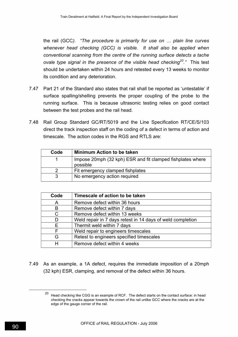
Train Derailment at Hatfield: A Final Report by the Independent Investigation Board
OFFICE of RAIL REGULATION - July 2006 90
the rail (GCC). “The procedure is primarily for use on … plain line curves
whenever head checking (GCC) is visible. It shall also be applied when
conventional scanning from the centre of the running surface detects a tache
ovale type signal in the presence of the visible head checking20.” This test
should be undertaken within 24 hours and retested every 13 weeks to monitor
its condition and any deterioration.
7.47 Part 21 of the Standard also states that rail shall be reported as ‘untestable’ if
surface spalling/shelling prevents the proper coupling of the probe to the
running surface. This is because ultrasonic testing relies on good contact
between the test probes and the rail head.
7.48 Rail Group Standard GC/RT/5019 and the Line Specification RT/CE/S/103
direct the track inspection staff on the coding of a defect in terms of action and
timescale. The action codes in the RGS and RTLS are:
Code Minimum Action to be taken
1 Impose 20mph (32 kph) ESR and fit clamped fishplates where possible
2 Fit emergency clamped fishplates
3 No emergency action required
Code Timescale of action to be taken
A Remove defect within 36 hours
B Remove defect within 7 days
C Remove defect within 13 weeks
D Weld repair in 7 days retest in 14 days of weld completion
E Thermit weld within 7 days
F Weld repair to engineers timescales
G Retest to engineers specified timescales
H Remove defect within 4 weeks
7.49 As an example, a 1A defect, requires the immediate imposition of a 20mph
(32 kph) ESR, clamping, and removal of the defect within 36 hours.
20
Head checking like CGG is an example of RCF. The defect starts on the contact surface: in head
checking the cracks appear towards the crown of the rail unlike GCC where the cracks are at the edge of the gauge corner of the rail.

Train Derailment at Hatfield: A Final Report by the Independent Investigation Board
OFFICE of RAIL REGULATION• July 2006 91
7.50 According to RT/CE/S/103 rail identified as untestable or total LORB due to
tache ovale defects should be dealt with in two ways:
I. place the rail back in for retest as Code 3G, and
II. submit site for inclusion in the future rail grinding programme.
7.51 In October 1999, BBRML were instructed within their contract that upon
detection of tache ovale type defects in declared GCC locations, the operator
must undertake U14 examination to both sides of the rail head. This alerted
BBRML staff to the possible growth behaviour of GCC defects.
7.52 It became clear to the Industry in early 1999 that RCF/GCC defects identified
in rail were not properly addressed by suitable action coding in the Standards
framework and defects were being retested rather than dealt with. This was
indicative of a standards driven approach to maintenance. However, IMCs
began to introduce local procedures to manage GCC sites.
7.53 On 8 November 1999 ECML zone issued a contract instruction to BBRML.
They required the IMC to identify problem sites where there was propagation
of GCC on high-speed high-canted track. They required samples from each
site to be sent for analysis. The contract instruction wanted priority to be
given to sites with MHT rail because GCC was developing at a faster rate on
these sites. A list was delivered early in December 1999.
7.54 Later in November 1999 at Aycliffe on the ECML(N), multiple GCC defects on
a high rail resulted in a rail break and emergency action to renew the rail.
This triggered a range of further actions and briefings on GCC defect
management within BBRML, Railtrack Zone and Railtrack Headquarters.
7.55 As a result of the rail break at Aycliffe, Railtrack’s Professional Head of Track
issued an important instruction detailing the action that should be taken for
loss of signal from the 70° probe i.e. loss of rail bottom as a result of gauge
corner cracking.
7.56 The instruction included specific directions on GCC defect management:
if the defect was isolated (length of 5m) and could be clamped, then
the rail should receive a 20mph (32 kph) ESR and be removed in 7
days.
Train Derailment at Hatfield: A Final Report by the Independent Investigation Board
OFFICE of RAIL REGULATION - July 2006 92
If the defect could not be clamped it had to be removed within 36
hours.
If the defect was considered to be a multiple defect then a 20mph (32
kph) ESR was to be applied and the rail removed in 36 hours.
This action corresponds to the defect coding 1A in the tables above.
7.57 In routine inspections the URFDOs identified a defect by marking the rail with
paint, then recording location, type and size of the defect on Test Form B.
Form B must be completed within 24 hours by the URFDO or by the RSM if
found by his visual examination.
7.58 The amendments to the framework of Standards and instructions
demonstrated that adequate arrangements were in place for monitoring and
improving defect management where action was required.
7.59 Following the derailment Railtrack issued further guidance and more detailed
information about RCF/GCC for URFDOs.
7.60 However, for the testing system to succeed, the Contractor had to have in
place effective briefing arrangements and checks to ensure compliance with
current instructions. The Investigation found that BBRML failed to achieve
these requirements.
The Management of Ultrasonic Testing
7.61 URFDOs from the Hitchin Depot carried out ultrasonic testing examinations
on the Down Fast line through Welham Green curve. They were supervised
by the same RSM as the patrolmen. The Block Item Manager (BIM) who
directed them to undertake inspections also managed them. It was the
responsibility of the RSMs to act upon the defects found by URFDOs. Further
ultrasonic testing may also have been required had defects been found by
track patrollers, welders, track engineers, RSMs etc.
7.62 There should have been an annual plan for the ultrasonic inspection of rails
based upon traffic frequencies and speeds, as directed by Standard
RT/CE/S/103. The Investigation was never provided with a written plan.
7.63 Although there was no written plan it would appear the URFDOs to some
extent managed themselves. The records show that the required general test

Train Derailment at Hatfield: A Final Report by the Independent Investigation Board
OFFICE of RAIL REGULATION• July 2006 93
(U3) for ultrasonic inspection through Welham Green curve was made at the
required six monthly intervals. However, the further tests required upon
identification of a defect were not carried out at the correct intervals.
7.64 URFDOs undertook inspection at Welham Green curve at night. The rail
defects noted were entered on a Form B that required details of the rail
defect. Each defect found, received a unique defect number. It was the
responsibility of the Technical Support Manager (TSM) to log the defects on a
database taking the information from the Form B. A copy of the form was
provided for the RSM.
7.65 During interviews with URFDOs, TSM and RSM staff it was evident that there
was confusion about who was responsible for coding the defects based on the
Group and Line Standards.
7.66 Of greater significance was the responsibility to complete the lower portion of
Form B. HSL examined a sample of the report forms for the Investigation. 16
forms had nothing entered under ‘action taken’; 23 had partial or incorrect
entries; 15 were correct and 5 had action exceeding the requirements of The
Standards.
7.67 The rail at Welham Green curve was continually retested and not the subject
of emergency action and re-railing in accordance with Railtrack Standards
and instructions. The lack of monitoring of this work by senior engineers
compounded this situation.
7.68 One reason for the failure was the inadequate internal briefing to BBRML staff
about the important instructions on LORB at GCC sites issued by Railtrack in
December 1999 that amended the action to manage RCF/GCC defects.
7.69 In evidence to the Investigation, BBRML claimed the amended instruction was
briefed to ECML(S) staff on 16 February 2000. However, this meeting was
attended by only a limited number of RSM/AME staff from the Kings Cross
section.
7.70 Minutes of the meeting recorded “there were no documents to brief”.
However, under Action 6 it was noted that “GCC was discussed in the light of
recent problems. All sites had been subject to joint visits and actions agreed”;
Action 7 noted “need to record when GCC is first recognised on
patrol/inspection”.
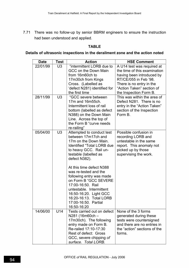
Train Derailment at Hatfield: A Final Report by the Independent Investigation Board
OFFICE of RAIL REGULATION - July 2006 94
7.71 There was no follow-up by senior BBRM engineers to ensure the instruction
had been understood and applied.
TABLE
Details of ultrasonic inspections in the derailment zone and the action noted
Date Test Action HSE Comment
22/01/99 U3 “intermittent LORB due to GCC on the Down Main from 16m60ch to 17m30ch from Kings Cross. (Labelled as ‘defect N281) identified for the first time
A U14 test was required at the time of this examination having been introduced by RT/CE/055 in Feb ’98.There is no entry in the “Action Taken” section of the Inspection Form B.
28/11/99 U3 “GCC severe between 17m and 16m55ch.Intermittent loss of rail bottom (labelled as defect N388) on the Down Main Line. Across the top of the Form B “curve needs re-railing”
This was within the area of Defect N281. There is no entry in the “Action Taken” section of the Inspection Form B.
05/04/00 U3 Attempted to conduct test between 17m17ch and 17m on the Down Main.Identified “Total LORB due to heavy GCC. Rail un-testable (labelled as defect N382).
At this time defect N388 was re-tested and the following entry was made on Form B “GCC SEVERE 17:00-16:50. Rail untestable. Intermittent 16:50-16:20. Light GCC 16:20-16:13. Total LORB 17:00-16:50. Partial 16:50-16:20
Possible confusion in recording LORB and untestable in the same report. This anomaly not picked up by those supervising the work.
14/06/00 U14 Tests carried out on defect N281 (16m60ch – 17m30ch). The following entry made on Form B. Re-railed 17:10-17:30 Rest of defect: Gross GCC, severe chipping ofsurface. Total LORB.
None of the 3 forms generated during these tests were countersigned and there are no entries in the “action” sections of the forms.
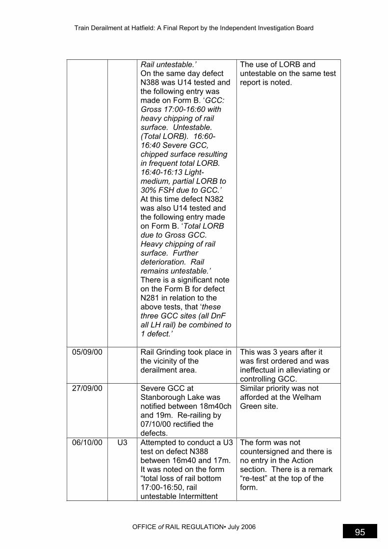
Train Derailment at Hatfield: A Final Report by the Independent Investigation Board
OFFICE of RAIL REGULATION• July 2006 95
Rail untestable.’ On the same day defect N388 was U14 tested and the following entry was made on Form B. ‘GCC:Gross 17:00-16:60 with heavy chipping of rail surface. Untestable. (Total LORB). 16:60-16:40 Severe GCC, chipped surface resulting in frequent total LORB.16:40-16:13 Light-medium, partial LORB to 30% FSH due to GCC.’ At this time defect N382 was also U14 tested and the following entry made on Form B. ‘Total LORB due to Gross GCC.Heavy chipping of rail surface. Further deterioration. Rail remains untestable.’ There is a significant note on the Form B for defect N281 in relation to the above tests, that ‘thesethree GCC sites (all DnF all LH rail) be combined to 1 defect.’
The use of LORB and untestable on the same test report is noted.
05/09/00 Rail Grinding took place in the vicinity of the derailment area.
This was 3 years after it was first ordered and was ineffectual in alleviating or controlling GCC.
27/09/00 Severe GCC at Stanborough Lake was notified between 18m40ch and 19m. Re-railing by 07/10/00 rectified the defects.
Similar priority was not afforded at the Welham Green site.
06/10/00 U3 Attempted to conduct a U3 test on defect N388 between 16m40 and 17m.It was noted on the form “total loss of rail bottom 17:00-16:50, rail untestable Intermittent
The form was not countersigned and there is no entry in the Action section. There is a remark “re-test” at the top of the form.

Train Derailment at Hatfield: A Final Report by the Independent Investigation Board
OFFICE of RAIL REGULATION - July 2006 96
LORB 16:50-16:40. All caused by severe GCC.Gross chipping of rail surface in places.”
7.72 These records showed that the U3 examinations at Welham Green curve
were made at the required frequencies, however, the additional testing using
the U14 procedure was not done in accordance with the Standards, e.g., tests
in February 00 and April 00 did not occur.
7.73 From the above records, it is clear that as early as January 1999, the rail at
Welham Green curve was in poor condition and the URFDOs were having
difficulties in carrying out tests. By the end of December 99, there were two
separate RCF/GCC defect references for Welham Green curve in the defect
database.
7.74 Had BBRML staff in ECML(S) followed the amended instructions issued by
Railtrack in December 99, the rail at Welham Green curve should have been
removed by April 2000.
7.75 The rail at Welham Green curve was identified for grinding in April 1997.
BBRML submitted applications again in 1998, 1999 and 2000. Grinding
occurred on 5/9/00. A month later, the site was ultrasonically tested and the
defects remained. Having the rail profile ground to comply with the Standard
and still being unable to examine the inside of the rail, should have indicated
the severity of the problem with the rail head. This should have stimulated a
site visit by track engineers and emergency action should have been taken.
Management of Defects found by Inspection and Testing
7.76 The testing and inspection procedures aimed to identify defects with an
immediate safety implication. Management of the defects required remedial
action within an organised and prioritised maintenance plan based on the risk
presented by the defect or multiple defects at any location.
7.77 BBRM used a computer database to control the management of defects and
planned maintenance. RT/CE/S/103 required that the database of defects
must show as a minimum:
Location of defect

Train Derailment at Hatfield: A Final Report by the Independent Investigation Board
OFFICE of RAIL REGULATION• July 2006 97
Type of defect (with code)
Date defect found
Defect number
Date when defect must be removed/repaired/retested (in accordance
with the minimum action sheets)
Date when defect removed/repaired/retested (if repeated retests are
required, the record must show the number of tests carried out and the
date of the last test)
Action plans for the removal of defects to meet the timescales specified
on the minimum action sheet, must be produced
7.78 There was a separate BBRML computer database known as IMPART used to
plan track maintenance work. Defects were entered from track inspection
reports and ultrasonic Form B for rectification planning. The database would
identify the relevant timescales according to the Standards and work that was
overdue. The maintenance plan for Kings Cross AME, was prepared, based
on the information on IMPART. However, a weakness of the system was that
IMPART did not contain all the defect information.
7.79 At the start of 2000 a considerable backlog of overdue defects had built up
throughout the Kings Cross AME.
7.80 In January 2000, the RSM at Finsbury Park noted that a large number of
defects were being retested instead of being dealt with as priority work. In
March he wrote to his senior engineer to advise him that he had reached the
point where he was unable to manage the situation.
7.81 From January until June 2000 there were a number of exchanges between
BBRML and Railtrack Zone and Railtrack Headquarters about the problem of
the growing backlog. By 1 June, Railtrack/BBRML had prepared a list that
included the following defect information for ECML(S):
2H – 10 defects to be removed within 4 week – 7 were overdue
3C – 66 defects to be removed within 13 weeks – 19 were overdue
89 weld repairs within 3 months – 41 were overdue

Train Derailment at Hatfield: A Final Report by the Independent Investigation Board
OFFICE of RAIL REGULATION - July 2006 98
30 of 54 retests were overdue although the rail in the derailment zone
was up to date.
7.82 In response to this situation, in June 2000, BBRML recruited an additional
sixteen staff to Kings Cross AME and seconded an additional AME to the
section to produce and manage a backlog recovery plan. However, within the
recovery plan, there was no evidence of any risk assessment21 to determine
likely rail failures and no action to impose interim speed restrictions at any of
the sites with the most serious defects.
7.83 In July, the BBRML Civil Engineer, his predecessor and the seconded AME
met to oversee the recovery plan. Senior engineers considered that the list of
scheduled events prepared provided a sound management of the problem
and for the backlog to be cleared within three months. The recovery work
was incomplete at the time of the derailment.
7.84 The Investigation could not establish why the backlog of defects was allowed
to build up. Clearly, BBRML’s inability to comply with the Standards in
managing defects was a major factor but the overriding concern was the
absence of a risk assessment at priority sites such as Welham Green curve.
7.85 Those responsible for overseeing the recovery plan should have considered
the information collected in connection with urgent re-railing proposals.
BBRML had collated a prioritised list of sites on ECML(S) where RCF/GCC
was present. Welham Green curve was at the top of this list – see Chapter 8.
Conclusions on the BBRML Maintenance Performance
7.86 The Investigation identified evidence to show that BBRML’s failure to maintain
the rail in the derailment zone was due to a number of significant
shortcomings in inspection, defect management procedures, the ability to
carry out risk assessments and staff competencies.
At all levels, BBRML employees failed to follow instructions and comply
with Railway Group Standards. In particular, key reporting and
minimum action requirements were ignored when severe RCF/GCC
21
A risk assessment is a process that begins with the identification of a hazard that could reasonably
be expected to cause significant harm, e.g. broken rail and/or derailment, and then deciding what control measures, actions or precautions are needed to control the risk from the identified hazard.
Train Derailment at Hatfield: A Final Report by the Independent Investigation Board
OFFICE of RAIL REGULATION• July 2006 99
and gross rail head shelling/spalling, was detected during patrols and
testing.
BBRML failed to identify the technical difficulties facing the NDT
operators and failed to brief the URFDOs fully about GCC including the
amended instructions issued in December 1999.
There were persistent failures to corroborate the ultrasonic findings
relating to RCF/GCC in the derailment zone.
In a number of key areas relating to RCF/GCC staff were not
competent to carry out their responsibilities notably in identifying this
type of defect or in applying risk assessment to prioritise decision
making. There was a predominant culture of assessing GCC on the
basis of visual examination without reference to the ultrasonic data.
Some track engineers received no training on track defects and the
safety related importance of defect management.
There was inadequate management of the rail inspection process at all
levels in the southern section. The quality of work was not properly
verified.
There was a failure to audit the management of defects in accordance
with the Standards.
These management faults were not addressed during 98/99/00 in
ECML(S).
BBRML failed to provide a safe system of work to enable employees to
carry out effective inspections in areas such as the Welham Green
curve. Such difficulties were not communicated through line
management to be dealt with.
There was a discrepancy in the number of recorded defects between
IMPART and the Defects Data Base. Defects in the rail at Welham
Green curve were entered in IMPART but not labelled as 1A defects.
Other sites with less severe RCF/GCC defects were categorised as 1A
defects. At a meeting of senior BBRML Engineers in July 2000, it was
estimated that only 30% of defects were being entered in IMPART.

Train Derailment at Hatfield: A Final Report by the Independent Investigation Board
OFFICE of RAIL REGULATION - July 2006 100
In managing the defects identified and quantified by the inspection and
testing activities, BBRML failed to carry out risk assessments to decide
their actions in non-compliance situations.
Summary
7.87 The Contractor Safety Case (CSC) lists a number of control measures to
prevent a derailment – see paragraph 7.5. The investigation found failures in
a number of the stated control measures.
Compliance with RGS
BBRML failed to comply with Group Standards, Line
Standards/specifications and some of its own procedures with respect
to managing defects in the rail at the Welham Green curve over a
considerable period of time.
BBRML identified the state of non-compliance but failed to take
reasonably practicable precautions to control the risk.
Training and Competence of Staff
Staff on ECML(S) were not properly trained to identify rolling contact
fatigue.
URFDOs were inadequately briefed on the amended instructions to
deal with tache ovale type defects.
There was a failure to carry out risk assessments when making
decisions to manage defects and prioritising the rail at Welham Green
curve.
Line Managers lacked the necessary knowledge of ultrasonic
inspections to address the difficulties encountered by URFDOs in fully
identifying the extent of GCC sites.
Planned Inspections
Routine inspections by RSMs were not carried out to the required
standards for frequency and quality.
Train Derailment at Hatfield: A Final Report by the Independent Investigation Board
OFFICE of RAIL REGULATION• July 2006 101
The inspections carried out by engineers did not use the track reports
generated by URFDOs and patrollers.
Use of Ultrasonic Inspection
Some U14 tests were missed according to the timescales set down in
the Standards.
Report forms completed after inspection were missing important
information.
The “action” part on the report forms were not completed.
Repeated critical observations regarding the rail at Welham Green
Curve were not acted upon.
A number of these failings were compounded by human factors issues
Human Factors
The working environment was difficult and dangerous for those
undertaking patrols and track walks.
Within BBRML there were significant resource shortages that
generated pressures in particular on RSMs.
The frequency of staff changes in key posts contributed to a range of
failures to deal adequately with the situation at the Welham Green site.
The resource shortages and staff turnover resulted in the absence of
knowledgeable and experienced staff dealing with rail condition issues.
Ultrasonic testers were faced with technical shortcomings in the
identification and categorisation of severe RCF/GCC sites. BBRML
were unable to respond effectively to this.
Ultrasonic testers in particular were de-motivated by the failure of
supervisors to apply the necessary emergency action in response to
their reported findings.
7.88 A summary of the work undertaken to implement the Board’s
recommendations can be found at Appendix 6.

Train Derailment at Hatfield: A Final Report by the Independent Investigation Board
OFFICE of RAIL REGULATION• July 2006 103
8. Railtrack’s Performance Managing the Maintenance of Rail on East Coast Main Line (South)
Background
8.1 Railtrack had a statutory duty to ensure the overall safety of the infrastructure.
In order to do so, it had to monitor the tasks carried out by its contractors.
The Investigation focussed on its supervisory role of the maintenance
contractors and in particular BBRML.
8.2 Railtrack’s responsibilities were to:
Monitor the performance of the contractors
Monitor the systems of the contractors
Retain details of the monitoring in an audit system
Issue corrective action reports in the event of failures being identified
Manage the corrective action reports to ensure that the failure had
been rectified
8.3 In addition to the day-to-day maintenance work required, Railtrack had the
overall responsibility for ensuring that track was renewed as it approached the
end of its normal operational life span.
8.4 Railtrack subcontracted the maintenance work under contract Reference
RT1A and the renewals work to contractors under contract Reference RT16.
Organisation and Arrangements for Monitoring Contractors
8.5 The organisation of Railtrack, positions and responsibilities are at Appendix 9
together with responsibilities of individual postholders.
8.6 The derailment at Welham Green curve occurred within Railtrack’s London
North East Zone (LNEZ). The LNEZ stretches from London Kings Cross
Train Derailment at Hatfield: A Final Report by the Independent Investigation Board
OFFICE of RAIL REGULATION - July 2006 104
Station to Tweedmouth (Scotland) and from west of Sheffield across to Hull.
This encompasses some 3000 miles 4828 km) of track.
8.7 The primary route within the zone is the 393-mile (632 km) long East Coast
Main Line (ECML) connecting London to Edinburgh. It carries 1,900
passenger trains and 250 freight trains per day.
8.8 Each of the seven Railtrack zones was responsible for the control and
operation of trains within it. Each zone held a number of infrastructure
maintenance and renewal contracts.
8.9 The Zone Director was responsible for all operational activities within his
zone. The Zonal Asset Manager was responsible for all maintenance
activities within the zone, including track. There was an Area Asset Manager,
responsible for monitoring the work on the ECML by BBRML.
8.10 There was a Maintenance Delivery Manager overseeing the work of the Kings
Cross AME, who in turn had a Programme Delivery Manager reviewing the
day-to-day work of BBRML.
8.11 The renewal contracts were controlled by Railtrack’s Project Delivery
Department. The Zonal Project Delivery Manager was responsible for all
renewal activities on the zone.
8.12 At Railtrack Headquarters, the Chief Executive and Operations Director held
regular high-level discussions with BBRML. Also the Chief Executive
received quarterly reports from the Zone Director on performance and
maintenance issues.
Information Relevant to Railtrack’s Performance
8.13 In 1995 HMRI carried out an inspection of Railtrack in relation to performance
of contractors working on infrastructure, and issued a report on 20 March
1996. Two Improvement Notices were served requiring an improved strategy
for monitoring contractors and compliance with group standards relating to
infrastructure maintenance.
8.14 On 2 February 1997 a freight train derailed at Bexley. HMRI’s investigation
showed that there were still problems with monitoring and auditing
contractors’ performance. The information in table 8.1 were among the

Train Derailment at Hatfield: A Final Report by the Independent Investigation Board
OFFICE of RAIL REGULATION• July 2006 105
recommendations and a summary of Railtrack’s response as set out in their
letter dated 3 June 1999 to HMRI.
Table 8.1
HSE Lesson Railtrack’s Response
Lesson 5. It is essential that each Railtrack Zone implement the Railtrack ‘Contract Performance Monitoring Strategy’. The resource required to implement and maintain this strategy should be identified and provided.
End product checks and management system checks are undertaken in accordance with a mandatory Line Procedure RT/D/P/015. All corrective actions resulting from the monitoring strategy are tracked and significant issues are raised at zonal supplier management groups, whose progress reports are reviewed.
Lesson 6. The individuals managing and implementing the ‘Contract Performance Monitoring Strategy’ should be competent to do so.
Specific competencies are described in job descriptions and safety responsibility statements. Training needs are identified and suitable training plans developed. New employees are reviewed to identify initial training requirements and a suitable training programme is then instigated.
Lesson 7. Each Railtrack Zone should ensure that they undertake ongoing monitoring and reassessment of their contractors’ performance in accordance with Contract Performance Monitoring Strategy.’
Monitoring and assessment in accordance with Line Procedures RT/D/P/015 and RT/D/P/022. ‘Contractor performance monitoring is undertaken via regular track inspections … If a system failure is identified via contractor monitoring process a CAR is issued on the contractor.
Lesson 8. Railtrack Zones and Railtrack headquarters should monitor and review the effectiveness of the systems they have in place to ensure the infrastructure is maintained in a safe condition. They should monitor and review the adequacy of the resource provided to undertake this.
Zones monitor contractor performance; there was a programme of infrastructure conditioning monitoring; a national task force to undertake independent review of asset condition; new Key Performance Indicators (KPIs) to monitor assets; improved maintenance regimes; and a new

Train Derailment at Hatfield: A Final Report by the Independent Investigation Board
OFFICE of RAIL REGULATION - July 2006 106
Lesson 9. Railtrack should ensure that they have adequate systems and procedures to not only identify failures by their contractor to maintain the infrastructure adequately but to ensure these failures are rectified.
maintenance regimes; and a new asset register.
8.15 The Investigation found no action had been taken on many of the above
items. If some of the measures described above had been implemented in
LNEZ during 2000, the risk of derailment at Welham Green would probably
have been eliminated since the zone would have become compliant with Rail
Standards.
8.16 Railtrack’s Railway Safety Case was subject to an annual independent
compliance audit. A significant finding of the 1999 audit was that Railtrack
failed to follow through to completion the action plans arising from their own
Safety Case audits. One example was the failure to implement the action
plan in response to the 1998 audit of Railtrack’s management of RT1A
contractors.
Railtrack’s Awareness of BBRML Failings
8.17 At Railtrack Headquarters between 1998 and 2000, briefings, reports and
discussions were frequently held on the topics of maintenance performance
and broken rail.
8.18 In July 1998, Railtrack cancelled an RT1A contract in the Bristol area due to
poor maintenance performance. The Chief Executive required all Zone
Directors to carry out a review of maintenance performance and implement
any necessary improvement programmes.
8.19 The minutes of a Railtrack Headquarters’ Committee meeting held on 7
September 1999 record that the need to manage the issue of broken rails
effectively was noted, and that this ‘would require a high level of physical
activity, planning, management and monitoring and would be critical in the
event of a fatality caused by a broken rail’.
8.20 Railtrack Headquarters had triggered a broken rail strategy in May 99 but by
September, the Chief Executive judged that it was not delivering the desired

Train Derailment at Hatfield: A Final Report by the Independent Investigation Board
OFFICE of RAIL REGULATION• July 2006 107
results and appointed an engineer to oversee the project and provide
additional focus.
8.21 In November 1999, Railtrack HQ considered providing an incentive bonus for
meeting track quality and broken rail targets. The minutes of the Directors’
meeting noted ‘over the life of the RT1A contracts, the contractors had failed
consistently to maintain and to renew the network at the anticipated levels’.
Railtrack did not introduce any such incentive.
8.22 In January 2000, Railtrack HQ wrote to BBRML warning of a contract
entitlement for Railtrack to recover £7.5m due to BBRML’s under-
performance. A week later, Zone Directors were told not to tolerate
inadequate maintenance. In February a Railtrack internal memo following a
review states ‘…. the results provide more than sufficient evidence to justify
real concern that our contractors do not have in place adequate, consistent
management procedures to ensure that the key risks are properly controlled
… The key issues identified are centred around inspections: resources and
competence. There are maintenance deficiencies too…it is self-evident that
inadequacies in any of these areas leave us exposed to risk of derailment,
collision and possibly other potential multi-fatality incidents.’
8.23 In the two years prior to the derailment, maintenance performance, rail breaks
and in particular management of GCC defects formed a large part of the
workload of the Professional Head of Track at HQ. There is much evidence to
show that he alerted Zone Directors, senior staff at Railtrack HQ, engineering
staff in the zones and the contractors responsible for maintenance and
renewal about the risk to safety.
8.24 There was a regular two monthly meeting between the Head of Track and
zone track engineers. The meetings were used to brief on new or revised
standards, key issues, lessons from incidents, and enabled the spread of best
practice
8.25 In May 1999 the Head of Track informed his senior colleagues: ‘a key driver
in the rise in the number of broken rails is the current poor maintenance or,
more precisely, the lack of adequate and appropriate maintenance being
carried out’.
Train Derailment at Hatfield: A Final Report by the Independent Investigation Board
OFFICE of RAIL REGULATION - July 2006 108
8.26 In August 1999, Railtrack’s Operations Director and Head of Track undertook
a track walk at Peterborough, ECML(S) and found ‘numerous examples of
lack of normal maintenance taking place’.
8.27 On 1 November 1999, the Head of Track wrote to colleagues at HQ
expressing his belief that there was significant non-compliance by Railtrack
zones to the inspection and response timescales for rail defects required by
RTLS and requested an audit.
8.28 He wrote on 2 November 1999 ‘there is now evidence to suggest that RT16
track renewals contract and our management of it are not delivering the track
renewals that we require’. In a further letter the following week he wrote
‘Conclusion – I do not believe that we can continue to delude ourselves that
the assumptions on which our submissions to the ORR are based are correct
in the light of significant traffic growth over the last 5 years and poor quality
maintenance and renewal. The current state of the track on parts of our
network is heading towards the boundary of acceptability’.
8.29 On 13 November the Head of Track wrote to Railtrack’s Head of Safety and
Risk Management stating ‘I believe from personal inspection of track and
discussions with zonal and contractors’ staff that there is widespread non-
compliance with Standards and good practice which is not visible through the
above process. There are many cases where non-availability of possessions
is preventing proper maintenance and compliance with Standards. The
balance between commercial drivers and safety are currently overwhelmingly
towards the commercial. The culture in the Company is currently such that
Zone Track Engineers are in fear of losing their jobs if they do not accept non-
compliance. They are also inadequately resourced to carry out their
responsibilities. I am particularly concerned that the number of broken rails
and the condition of the track in some locations is providing an intolerable risk.
We are certainly not within ALARP 22.’
8.30 In the week before the derailment, the Head of Track expressed concern
regarding the general state of track maintenance and identified derailment
due to broken rail, as a scenario for a possible multi-fatality incident, and in a
22
ALARP is short for “as low as reasonably practicable”. This involves weighing the risk against the
trouble, time and money needed to control the risk. Thus, ALARP describes the level to which we expect to see workplace risks controlled.

Train Derailment at Hatfield: A Final Report by the Independent Investigation Board
OFFICE of RAIL REGULATION• July 2006 109
memo dated 13 October 2000, states ‘the significant increase in broken rail
numbers and growth in traffic is increasing the risk of derailment’.
8.31 The Investigation noted the comments made by the Industry Formal Inquiry
Panel about the depression of the professional engineering role within
Railtrack HQ and LNE zone levels. Following the derailment changes were
introduced at Railtrack HQ that resulted in the appointment of a Technical
Director to the main Railtrack Board and a Chief Engineer reporting to that
Director
8.32 The Investigation concluded that within Railtrack, the Professional Head of
Track did not have the authority or resources to bring about improvements in
these areas of concern. It is clear that he alerted senior colleagues to the
non-compliant state of rail maintenance, however, Railtrack as an
organisation, failed to implement and monitor his advice to ensure rails were
properly maintained.
8.33 At zone level, the Zone Director and his staff applied to BBRML the reviews
from Railtrack HQ on quality of maintenance work and initiatives on broken
rail.
8.34 In addition at zone level the Investigation found a longstanding awareness
and a history of criticism of BBRML’s poor maintenance performance.
8.35 From early in 1998, the Zone Director was in discussion with BBRML about
broken rail problems on ECML and linked these to poor quality of
maintenance work and non-compliance with Rail Standards.
8.36 In January 1999 Railtrack’s Zone Director expressed concern that the number
of broken rails had increased sharply and asked for the reasons to be
investigated. BBRML’s reply was that they needed possession of the line to
do the work. However, Railtrack noted that BBRML had itself cancelled
possessions.
8.37 On 2 August 1999 the zone told BBRML, “the evolution of the issues currently
emerging for track quality have proven without a doubt your organisation was
inadequately managed (hence our crisis session)”. The crisis session
concerned overhead line equipment.

Train Derailment at Hatfield: A Final Report by the Independent Investigation Board
OFFICE of RAIL REGULATION - July 2006 110
8.38 On 19 May 2000, the Zone Director wrote to BBRML ‘it is very clear from
recent events that you are not providing resources adequate to tasks and
scope of the maintenance contract…I must formally give notice that we are
considering whether to bring in another contractor to supplement your
shortfalls on the route, counter-charging costs incurred to BBRML.’
8.39 After the derailment, on 21 October 2000, the Zone Director wrote to the
Managing Director of Balfour Beatty Rail Ltd, the parent company of BBRML,
stating, “The Hatfield accident has shown that the mechanisms within our
maintenance contract, designed to ensure a safe railway, have not been
working. There has been a terrible failure in the total management process
involving us and yourselves. In addition, various earlier incidents, including
(as examples) Bexley, Rivenhall and Harwich have also indicated shortfalls in
process, performance and management. In endeavouring to work together to
ensure the over-riding needs of public safety, these events seriously rock our
confidence in the arrangements between us, and in our execution of your
obligations.”
Railtrack’s Performance – Management of Backlog of Defects
8.40 Within the Railtrack network there was no system in place that allowed
Railtrack to view the total number and types of rail defects present in their
infrastructure at any one time. Railtrack’s Asset Database was incomplete
and inaccurate as to what assets they had, their condition, and expected life
expiry. For example, the rail at Welham Green was entered in the database
as 1982 rail which was the last complete track renewal, but over succeeding
years it was replaced in 1995 with mill heat treated rail. Railtrack relied on
information from the various maintenance contractors who all ran different
databases.
8.41 During the audit of the RT1A contract for 2000, the audit team visited
BBRML’s office at Hitchin on 20 and 22 March 2000. It was noted that retests
required by the standards were not being completed within 3 months
(planning was to 6 months) and that defects were not being removed from
track within specified time scales and dispensations had not been sought.
Railtrack’s Maintenance Delivery Manager wrote to BBRML expressing
concerns. In May, Railtrack staff based at the Hitchin Depot confirmed the
scale of the defect problems. No risk assessment was made to establish the
impact on safety of these findings.
Train Derailment at Hatfield: A Final Report by the Independent Investigation Board
OFFICE of RAIL REGULATION• July 2006 111
8.42 It was clear at this time that BBRML (and consequently Railtrack) was non-
compliant with the safety standards with respect to the Code 1A type defects.
In order to allow the contractor to put together a ‘recovery plan’ for these
defects, the Zonal Track Engineer at Railtrack proposed that a general ‘time
dispensation’ be granted in respect of these. This would allow the contractor
to carry out the rectification work over a longer period. Railtrack confirmed
this decision in a letter to BBRML dated 13 June 2000.
8.43 This particular approach was unique in the experience of the relevant
Railtrack staff. There was no application for a derogation, although there was
a clear procedure set out in the Standards. No risk assessments were made
and no formal plan for recovery as specifically required in the Standard was
produced. Also, by keeping the management of the process within the zone,
Railtrack HQ was not kept informed.
8.44 In order to effectively supervise the work of BBRML within their
statutory responsibilities, Railtrack should have taken a number of preventive
actions when the extent of BBRML’s non-compliance became apparent in
March 2000 in particular the failure to remove defects within the required time
period. In order to make the situation compliant with Rail Standards, at zone
level, Railtrack needed to:
discover the full extent of the problem – location, numbers, seriousness
arrange for each site to be risk assessed
prioritise the defects
apply any mitigation arising from these actions
deal with the systemic failures in BBRML within the audit mechanism
8.45 The scale of this failure was made greater by the existence at this time of a
prioritised list of sites with serious GCC defects – drawn up by zone and
BBRML engineers for managing the renewals process.
Railtrack’s Performance – Use of Audits
8.46 Audit is a structured process of collecting independent information on the
effectiveness, efficiency and reliability of the management system under
examination and drawing up plans for corrective action. Standard

Train Derailment at Hatfield: A Final Report by the Independent Investigation Board
OFFICE of RAIL REGULATION - July 2006 112
RT/LS/P/036 Railtrack Company Procedure “Railtrack Audit Manual” provided
direction and guidance to Railtrack staff on the general principals of
management system and technical auditing, the management of audit
programmes and the process to be followed. The guidance is applied to all
audits initiated by Railtrack.
8.47 Railtrack’s Safety Case states that specialist engineers ‘have an ongoing
programme of planned technical audit of maintenance and project activities to
verify that the required levels of maintenance, testing and inspection are
undertaken’.
8.48 The Safety Case also states that Railtrack has ‘a comprehensive audit system
which confirms…contractors’ safety performance against their Assurance
Case…the term “audit” is used by Railtrack to mean: “A systematic and
independent examination to determine whether activities and related results
comply with planned arrangements and whether these arrangements are
implemented effectively and are suitable to achieve these objectives”’. The
section on Audit Arrangements in the Rail Safety Case makes other
statements concerning organisation, planning and implementing, measuring
and reviewing performance.
8.49 Railtrack’s Line Procedure RT/D/P/022 dated August 1999 and implemented
7 August 1999 requires that all deficiencies identified in contractor
management systems shall result in the issue of a Corrective Action Report
(CAR). In response the contractor is instructed to submit an action plan to be
reviewed within an agreed timescale. Once the corrective action is
completed, Railtrack decides whether the CAR can be signed off. However,
there is no provision for action to be taken if CARs become overdue or if the
contractor is unable to meet acceptable standards.
8.50 Line Procedure RT/D/P/015, dated April 2000 and implemented 1 April 2000,
aims to provide Railtrack with the confidence that the contractors’
management systems are effective and their end products acceptable. This
procedure defines a contract check as an activity that assesses the extent to
which the contractors’ work, procedures or systems, meet the contractual
obligations. It includes end product checks (EPC), defined as a check carried
out in one or more critical end products to validate the effectiveness of the
related management system. The management system is defined as the
Train Derailment at Hatfield: A Final Report by the Independent Investigation Board
OFFICE of RAIL REGULATION• July 2006 113
contractors’ provisions for planning, controlling, documenting, recording and
checking all its work activities.
8.51 The Investigation found that the EPC to be applied as part of the audit regime
were heavily focussed on document examination rather than checking the
condition of the rail. Also, the emphasis was on achieving the target number
of EPC rather than giving time to addressing the deficiencies revealed in the
checking process. Although standard RT/D/P/015 contains EPC activity for
patrolling, ultrasonic inspection, rail replacement, and defect management
there are no questions relating to the evaluation of track quality.
8.52 Railtrack’s Director of Safety and Assurance carried out a technical audit of
LNEZ’s track engineering in June 2000. This was aimed at examining the
management Standards in place to ensure compliance with all RGS and line
specifications. RT/CE/S/055 ‘Rail Testing: Ultrasonic Procedures’,
RT/CE/S/057 ‘Rail Failure Handbook’ and RT/CE/S/103 ‘Track Inspection
Requirements’ were specifically audited. Two audit questions referred to the
management of GCC. No deficiencies in complying with these Specifications
were revealed by the audit.
8.53 The audit raised no Corrective Action Reports but made four observations.
The report noted that the Track Engineer had little time for attacking key
strategic issues and for track walking. The audit concluded that LNEZ was
compliant with those standards audited with the exception of agreed non-
compliances. Examination of the audit report showed that many questions on
the audit schedule had not been asked (over 50%). The reasons given were
lack of audit resource and availability of relevant staff to be audited. The
effectiveness of such a process is questionable.
8.54 A joint Railtrack / IMC audit of the delivery of the RT1A contract is conducted
annually in all zones in accordance with RT/D/P/022 and RT/D/P/015. The
last RT1A audit of BBRML’s organisation on the ECML before the derailment
was made between 13 March and 17 April 2000. The joint audit team visited
BBRML’s office at Hitchin on 20 and 22 March 2000 to audit the AME Kings
Cross area. The process carried out was examination of documents and
talking to staff. The audit was started but not finished. A consequent attempt
at a revisit failed because the personnel required to attend were unavailable.
After that attempt the RSM left BBRML and a reorganisation at Hitchin was
proposed. It was proposed that a new audit should be undertaken when the

Train Derailment at Hatfield: A Final Report by the Independent Investigation Board
OFFICE of RAIL REGULATION - July 2006 114
new post holders were in place. There is no evidence of a reorganisation at
Hitchin and the element of the BBRML audit of the Kings Cross area was not
completed.
8.55 The audit did note that retests were not completed within three months and
defects were not removed within the specified timescales and dispensations
had not been sought. CARs were to be issued on both irregularities.
However, a CAR was not issued until 27 October 2000 i.e. 10 days after the
derailment. BBRML prompted Railtrack about the CARs on 22 June 2000. It
is implicit that CARs should be issued immediately as the checking procedure
includes establishing whether the corrective action ‘immediately affects the
safety of the line’.
8.56 In Railtrack’s summary of the RT1A contract audit of BBRML, the Kings Cross
area audit was not described as partially completed. There was no reference
to the CARs due to be issued as a result of the ‘partial audit’. The final audit
summary has, as a specific purpose, the inclusion of all CARs issued or due
to be issued.
8.57 The Investigation revealed possible training deficiencies for some of the
Railtrack staff involved in the auditing process. Railtrack’s LNEZ Compliance
and Engineering Manager, in interview, said he was unable to follow
discussion of track work at Hitchin because of its technical nature. The Zone
Quality Standards Manager stated in interview ‘I do not have knowledge of
railway engineering nor railway safety’. The job description for Zone Quality
Standards Manager requires ‘excellent knowledge of railway engineering
safety and contractual matters’.
8.58 In April 2000 the relevant zone Managers and zone Director signed the
annual certificate of compliance for BBRML on LNEZ. This was despite the
absence of a completed RT1A audit and the failure to issue CARs.
8.59 The Investigation found that the audit process applied to BBRML was
ineffective, not thorough and not in compliance with Railtrack’s Safety Case
on auditing. It did not achieve the objective of contractor compliance and did
not address substandard practices. In particular:
Railtrack failed to fully implement the auditing system in respect of
BBRML on ECML in 2000.
Train Derailment at Hatfield: A Final Report by the Independent Investigation Board
OFFICE of RAIL REGULATION• July 2006 115
Railtrack failed to ensure BBRML acted upon serious shortcomings
identified in the partial audit process undertaken of the AME Kings
Cross.
Overall, the system was ineffective in correcting the failings identified
because of the over-emphasis on assessing documentary compliance
and did not carry out sufficient verification of the end products i.e. the
quality and outcome of maintenance work.
The final certificate of compliance for BBRML failed to alert Railtrack
HQ about the incomplete RT1A audit or the failure to issues CARs.
Failure to Renew the Rail at Welham Green Curve
8.60 In addition to day-to-day maintenance work, Railtrack had the overall
responsibility for ensuring that track was renewed as it approached the end of
its normal operational life span. Railtrack also had to undertake emergency
renewal of rail at sites such as Welham Green curve where the rail had
deteriorated due to RCF/GCC at a faster rate than expected.
8.61 In Railtrack LNEZ Project Delivery is the Department who undertake the
replacement of all infrastructure items. Within the Department, there are
disciplines to concentrate on specific issues, e.g. track.
8.62 The LNEZ Asset Manager is the ‘client’ for the replacement of the track at
Welham Green curve, the LNEZ Business Development Unit controls the
money for the renewal projects, Project Delivery plan the work to be
undertaken and Jarvis Rail were the contractors operating under contract
RT16 to re-rail Welham Green curve.
8.63 Railtrack’s planned method for renewing rail was inherited from British Rail.
8.64 Under this renewals policy, in order for assets to be renewed on LNEZ, the
maintenance contractor BBRML had to identify that an asset would become
‘life expired’. Under the policy, the aim was to identify work four years in
advance of the perceived expiry date. BBRML undertook this assessment on
the basis of maintenance records and an assessment of asset condition.
8.65 BBRML submitted ‘Renewal of Way’ (ROW) forms to Railtrack specifying the
track due for replacement and the time by which the job must be completed.
After the expiry of this date, a temporary speed restriction would be required.
Train Derailment at Hatfield: A Final Report by the Independent Investigation Board
OFFICE of RAIL REGULATION - July 2006 116
The Investigation could not find a ROW proposal form for the rail at Welham
Green curve.
8.66 In interviews with Railtrack staff it was clear that the planned renewal process
was not achieved. The relevant Zone Investment Panel approved all renewal
work. Between 1998 and 2000 most zones identified a growing work bank of
renewals i.e. more renewals proposed than completed.
8.67 The strategy for renewals was based on historic traffic data and therefore it
was potentially flawed. The projected criteria used in the strategy did not
accurately reflect the increased freight and passenger traffic volumes post
privatisation and the changes in rail-life expectancy particularly on high-speed
routes with heavy traffic. Also the strategy did not take into account the lower
standards of rail maintenance in some zones.
8.68 In addition to the renewals procedure LNEZ and BBRML were part of an Area
Delivery Group (ADG). The ADG was seen as a way of obtaining funds for
re-railing works outside the normal ROW planned route. Its objective was to
consider re-railing proposals in order to improve train performance and it
provided a means of addressing the growing demand for re-railing due to
RCF/GCC.
8.69 In the minutes of the ADG meetings for LNEZ, there were references to
increases in incidences of GCC on 16/02/99, 16/03/99, 13/04/99 and 28/09/99
and the ADG requested a list of GCC sites from BBRML. The list, which
included the Welham Green curve, was provided in December 1999.
However, the ADG took no further action on GCC sites, firstly because of the
large numbers in relation to their budget and also at this time, Railtrack zone
engineers adopted a separate renewals initiative for GCC sites following the
rail break at Aycliffe on ECML(N).
8.70 As part of the post-Aycliffe action, Railtrack arranged for engineers to inspect
and prepare a prioritised list sites with cases of GCC. The inspection team
was made up of 2 engineers, one from Railtrack and one from BBRML.
8.71 As part of this process, the Down Fast at Hatfield and the Down Fast at
Welham Green were dealt with as two separate sites. The Hatfield site was
17 miles 20 chains (27.761 km) to 17miles 70 chains (28.767 km) and the
Welham Green site was 16 miles 09 chains (25.931 km) to 17 miles 17 chains
(27.701 km) (the latter included the Welham Green Curve). Engineers

Train Derailment at Hatfield: A Final Report by the Independent Investigation Board
OFFICE of RAIL REGULATION• July 2006 117
assessed the Hatfield site on 21 December 1999 and proposals for re-railing
were submitted on 4 January 2000. The engineers assessed the Welham
Green site on 15 February 2000. No documents were discovered relating to
the conduct of the assessments or establishing how much was actually
assessed.
8.72 The Project Manager of LNEZ Project Delivery Renewals received a list of re-
railing items identified on ECML with GCC problems, some similar to those at
Aycliffe. The Project Manager recommended that in order to avoid a similar
emergency, urgent delivery and installation of rail was required at all sites
marked Priority 1. Fourteen GCC sites were identified in which the top 3
entries are:
Location ELR Track Start Mileage End Mileage Type of Priority
Mile Yards Miles Yards Defect
WGreen ECML DnF 16 198 17 374 GCC 1
WGreen ECML UpF 16 198 17 374 GCC 3
Hatfield ECML DnF 17 572 17 1496 GCC 1
8.73 In the list submitted to the project manager, Railtrack LNEZ Track
Engineers defined re-railing under the Priority Codes as:
P1 – 1 month,
P2 – 6 months,
P3 – 12 months.
8.74 The allocation of priorities P1 – P3 was not a recognised process for track
renewals. The usual way for conveying the immediate urgency for carrying
out an item of track renewal was by indicating the imposition of a temporary
speed restriction (TSR) as at Aycliffe. The item for re-railing of the high rail
around the Welham Green Curve carried no such indication. Never the less a
requirement to renew within one month should have indicated to Railtrack’s
renewal planners that this was a matter of urgency. The Investigation found
no reference to the consideration of imposing TSRs at the six sites identified
as Priority 1.
8.75 However, at a meeting on 2 March 2000 between Railtrack and the renewals
contractor Jarvis it was agreed that assigning 1 month for Priority 1 sites was

Train Derailment at Hatfield: A Final Report by the Independent Investigation Board
OFFICE of RAIL REGULATION - July 2006 118
unachievable. An alternative deadline for these sites was not given nor was it
considered necessary to impose TSRs at these sites.
8.76 Railtrack was responsible for facilitating suitable possessions and rail
availability in order to renew rail at the priority sites. However, the
Investigation found that although the urgency for re-railing had been identified
in February 2000, due to poor planning and organisation of Railtrack, the rail
at Welham Green curve was not renewed before the derailment.
8.77 On 29 March 2000, the Railtrack Planning System for re-railing designated
the work at the Welham Green site to take place between 13 May and 29 May
2000. (Hatfield had been planned for various dates from March 2000 onwards
and was eventually completed on 21 May 2000).
8.78 On 30 March 2000, BBRML wrote to Railtrack advising that the Down Main
was very poor and on 3 April Railtrack replied “this site is indeed in very poor
condition and as such, has been assessed as Priority 1 which is to be
undertaken during the 3rd week in April.” This was a clear indication that
both BBRML and Railtrack were aware of the severe GCC problems in the
derailment area by moving the planned date for rail renewal forward by a
month.
8.79 On 6 April 2000, Railtrack’s Zone Investment Panel met to discuss a Track
Quality Progress Report and authorise GCC renewals. The report said:
“GCC has been identified as a significant problem on LNE… the extent
of the problem has now been quantified and prioritised by the Zone
Track Engineer, a list of sites is given in Appendix F. At priority 1 sites
re-railing is the only solution, this has been planned and additional
authority of £913k is sought for this work.
Appendix F – The following timescales apply to the priorities listed as
defined by the Railtrack LNEZ Track Engineers.
P1= 0 – 6 months, P2 = 6 – 12 months, P3 = 12 – 18 months”.
8.80 The Welham Green site headed the list in Appendix F. It remained a P1
priority. However, the timescales for completion had been varied significantly.
The Investigation could not confirm who was responsible for the changes.
Train Derailment at Hatfield: A Final Report by the Independent Investigation Board
OFFICE of RAIL REGULATION• July 2006 119
There is no evidence about how this was changed or evidence of any risk
assessment for the revised timescale.
8.81 On 28 April 2000, the rail for the renewal was delivered to the Welham Green
site. This was the fourth attempt at delivery after failures on 28 and 29 March
and 6 April 2000 and indicative of the extent of the poor planning and
organisation for re-railing.
8.82 On 3 May 2000, a progress meeting was held between Jarvis and Railtrack
about the renewal work. The planning of the work for the Hatfield and
Welham Green sites showed that the tasks were to run consecutively.
Unfortunately, when the work at Hatfield was completed by 21 May 2000, it
had over-run. It used up 2 of the 3 weekend possessions planned for the
Welham Green site, which were not replaced in any subsequent planning.
The Welham Green site renewal was postponed. This situation was further
aggravated by the limits to possession imposed by the summer network
timetable that commenced on 28 May 2000.
8.83 At a Renewals Planning Meeting on 31 May 2000 it was noted that no work
had been undertaken at the Welham Green site, and Railtrack had not set a
new date for re-railing of the site. This was an opportunity for Railtrack to
consider the emergency control measures (such as TSRs, clamping, etc.)
applied at Aycliffe but these were not put in place.
8.84 On 30 July 2000, an application was made for possessions to re-rail Welham
Green curve in December 2000. On 30 August 2000, an application was
made for possessions to re-rail Welham Green curve on various dates up to
28 January 2001. This second application proposed some interim temporary
speed restrictions. No action was taken but this was a further indication of the
seriousness of the severe GCC defects in the derailment area.
8.85 The list of GCC sites continued to include Welham Green curve without any
indication that action was pending by the beginning of October 2000. There
was no evidence of any reassessment. Later that month the derailment
occurred.
8.86 The process for the project management of rail renewals began satisfactorily.
However, as with the audit process and the oversight of defects management
within the LNEZ, Railtrack failed to provide the necessary levels of corrective
and preventive actions within a robust process, and further failed to assess
Train Derailment at Hatfield: A Final Report by the Independent Investigation Board
OFFICE of RAIL REGULATION - July 2006 120
the risk to safety of their decisions. There were opportunities at the progress
meetings to assess the need to impose TSRs. The investigation could find no
record of such discussions.
8.87 Railtrack failed to ensure the re-railing of the Welham Green site within one
month of 29/02/00 as a priority 1 site recorded on that date. Following the
extension of the re-railing period for priority 1 sites, Railtrack failed to ensure
the re-railing of the Welham Green site within 6 months of 06/04/00.
8.88 The staff had a variety of options at their disposal e.g. TSRs, clamping, etc,
but failed to implement any to control the danger at Welham Green curve and,
during the renewals projects, Railtrack failed to keep BBRML informed about
the failure to re-rail and the decision to postpone the work.
8.89 Railtrack discovered the extent of RCF/GCC on the ECML after the
derailment, and it is believed that there were 1,867 sites at which Temporary
Speed Restrictions were subsequently imposed as a result of RCF.
Rail Grinding
8.90 The Investigation found that Railtrack lacked an overall strategy to manage
the maintenance of rail. One aspect of rail maintenance that highlighted this
absence was the lack of an overall policy on the use of rail grinding as a
planned, preventive technique for rail maintenance.
8.91 Rail grinding is a process predominantly employed on heavily used rail to
restore rail profile and to remove surface damage. It is carried out by means
of a purpose built train fitted with banks of grinding stones. Contractors have
always undertaken rail grinding on the UK network. A contract existed
between Railtrack and SERCo Railtest since 1994. The latter, in turn,
contracted the work to Schweerbau (UK), the operator of the grinding train.
One grinding train was available for use on the whole of network in the years
before the derailment. It was allocated to Railtrack zones based on the
requests submitted by the maintenance contractors. The allocation was
determined in Railtrack HQ.
8.92 The specification in force for rail grinding required the production of a new rail
head profile to BS113A. There was no provision in the specification for
conformal profiling according to a particular route and the specification was
not designed for the elimination of defects. Typically, each pass of the

Train Derailment at Hatfield: A Final Report by the Independent Investigation Board
OFFICE of RAIL REGULATION• July 2006 121
machine removes 0.2mm of metal from the surface of the rail and 5 or 6
passes would normally be necessary to achieve a rail head profile in
accordance with the specification.
8.93 There was no coordination between the various contractors involved in
grinding and rail maintenance. This meant that BBRML was unaware when
grinding had taken place on ECML(S). The role of the grinding train operator
was to ensure that work was done according to the specification and did not
include the inspection of the surface finish.
8.94 The BBRML staff were not qualified to assess the quality of the grinding
carried out by the train operator. This was the responsibility of SERCo
Railtest. At the end of each grinding shift, the record of the profile achieved
was sent to the relevant Railtrack zone.
8.95 In December 1999, Railtrack wrote to contractors with guidelines that
amended the categorisation and action for GCC defects. This was not briefed
to the grinding contractor SERCo Railtest. The guidelines contained
reference to the frequency of grinding related to the tonnage of traffic carried
and also set out advice for grinding where GCC was present, but the
effectiveness and impact of the new advice was diminished by the lack of
consultation, failure to amend the rail grinding specification and by having only
one train available on the whole network for rail grinding. This meant there
was no plan in the grinding programme to deal with any short-term
requirements due to the increase in identification, and required action, for
managing RCF/GCC defects.
8.96 The Investigation found that very little rail grinding was done on the network
up to the end of 1999. For a long time, there had been insufficient grinding
capacity to meet the demands. Railtrack planned an increase in the grinding
programme during 2000/01. However, by July 2000, the promised increase
had not been achieved. During 2000, some grinding time was allotted to
grinding newly installed rail, but generally, had been used to improve the
quality of passenger ride.
8.97 The rail at Welham Green curve was identified to be ground in April 1997.
BBRML submitted an application again in 19998/99/2000. The rail was finally
ground on 4/5 September 2000.
Train Derailment at Hatfield: A Final Report by the Independent Investigation Board
OFFICE of RAIL REGULATION - July 2006 122
8.98 There was evidence to indicate a level of confusion about the purpose of
grinding the high rail at Welham Green curve. Railtrack believed that the
grinding carried out on 5 September 2000 would control the impact of
RCF/GCC pending the renewal of the rail. However, BBRML believed that
the rail grinding had been booked in anticipation that the high rail would have
already been renewed by September and not as a control measure for dealing
with RCF/GCC in the existing rail.
8.99 In a statement from the BBRML Regional Track Engineer, it was clear that he
considered the extent and severity of the RCF/GCC was well beyond the limit
where rail grinding would have any beneficial effect. In defence of the
decision to proceed, he said that the guidelines for rail grinding that were
available at the time were not particularly helpful, although they had improved
since as a result of an initiative by Railtrack. The ultrasonic operator who
carried out the last test before the derailment occurred observed that rail
grinding had taken place. The grinding had smoothed the gauge corner and
had taken out all the chippings along the edge. The grinding had no impact
upon the effectiveness of the ultrasonic testing which still registered total loss
of rail bottom (LORB) and rail untestable.
8.100 With particular regard to the rail at the derailment site, the Investigation found
that in general, the opinion was, that due to the extensive cracking that
existed in the rail, grinding would have been of no benefit. The spalling in the
rail head was in the order of 3mm deep which could not possibly be removed
by grinding.
8.101 The Technical Investigation conducted by HSL concluded that the residual
grinding marks on the rail head from the operation carried out on 5 September
2000 had not subsequently initiated cracking. In evidence given to the
Investigation, Corus (British Steel) the supplier of the rail strongly supported a
managed system to the problem of RCF/GCC that included both the
management of contact stresses and the control of crack propagation through
regular preventative grinding.
8.102 The frequency of grinding at any site is dependent on factors such as axle
load, traffic conditions, wheel condition and the wear rate of the steel. Such
assessments and the accompanying arrangements would clearly form an
element in a rail maintenance strategy along with the capacity to carry out a

Train Derailment at Hatfield: A Final Report by the Independent Investigation Board
OFFICE of RAIL REGULATION• July 2006 123
planned programme of rail grinding work that included reactive measures to
manage cases of emerging problems due to RCF/GCC.
8.103 During 2000 Railtrack formulated proposals to increase the capacity for rail
grinding by the delivery of an additional two new rail grinding trains.
Railtrack Performance – Underlying Causes
8.104 The Investigation identified a number of significant failings in Railtrack’s
performance that contributed to the failure to maintain the line in a safe
condition in the Welham Green area. The shortcomings showed Railtrack’s
inability to discharge its responsibilities to maintain a safe infrastructure and
effectively manage BBRML’s maintenance activities on ECML (S).
8.105 At the time of the derailment and over the previous two years, the culture
within Railtrack which conditioned decision making on safety and performance
issues, was biased towards performance-driven decisions. In particular, there
was a bias towards minimising train delays and quantifying rail failures in
terms of broken rails but failing to focus on the poor quality of maintenance
that was the root cause of the rail breakage.
8.106 Railtrack failed to apply thoroughly and effectively all the necessary
management monitoring systems and arrangements at their disposal to
ensure BBRML met their contractual standards on quality of maintenance.
8.107 In the 2 – 3 year period prior to the derailment, several senior staff in LNEZ
took BBRML to task for not achieving the required quality standards. During
this period they threatened the Contractor with punitive financial action in
order to seek improvements in performance. However, despite all the
criticisms, in June 2000, the Zone Director signed a certificate to inform
Railtrack Headquarters that LNEZ was in compliance as regards the
necessary standards.
8.108 The acceptance of a certificate of compliance did not require any supporting
evidence to verify the conclusion.
8.109 Over the ten years prior to the derailment, the rail industry’s knowledge of
RCF/GCC as a cause of rail breaks had increased. The industry was aware
of the technically difficult ultrasonic testing processes for identifying GCC

Train Derailment at Hatfield: A Final Report by the Independent Investigation Board
OFFICE of RAIL REGULATION - July 2006 124
defects, but it was only after the derailment that more complete guidance was
issued for patrollers and URFDOs – see Chapter 7.
8.110 The channels of communication within Railtrack and to Contractors were
sufficient to transfer this information but in LNEZ staff reacted in an
inconsistent and selective way that diminished the effects of the amendments
issued in December 1999 re GCC management.
8.111 Within ECML, Railtrack staff had practical experience of GCC issues in
particular following the incident at Aycliffe in November/December 99. Some
staff responded in a competent and professional manner to identify and
prioritise GCC sites in the Zone. At this point in time, the Welham Green area
topped the list of prioritised sites. However, Railtrack failed to follow the
modified instructions for GCC defects, failed to carry out mandatory
assessment of risk subsequent to decision making and failed to take the
necessary emergency action to impose TSRs, in particular at the Welham
Green curve.
8.112 In failing to carry out effective audit procedures, opportunities were lost to
correct the deficiencies in BBRML’s performance and impose emergency
requirements.
8.113 The Head of Track was significant amongst senior staff in identifying the
dangers on the network arising from poor rail condition allied to poor
maintenance performance. He made a number of unsuccessful attempts to
seek improvement in quality and maintenance standards. This was a clear
indication that Railtrack was not putting safety as the number one objective in
its maintenance strategy.
8.114 A summary of the work undertaken to implement the Board’s
recommendations can be found at Appendix 6.

Train Derailment at Hatfield: A Final Report by the Independent Investigation Board
OFFICE of RAIL REGULATION• July 2006 125
9. Legal Proceedings
Background
9.1 As set out in Chapter 1 The Work-Related Deaths Protocol sets out the
principles for effective liaison between the organisations responsible for
investigating work-related deaths in England and Wales. In accordance with
this Protocol the British Transport Police (BTP) took the lead in this
investigation and remained in the lead throughout.
9.2 At present, only the Police can investigate serious criminal offences (other
than health and safety offences) such as manslaughter, and only the Crown
Prosecution Service (CPS) can decide whether such a case will proceed.
9.3 Until 1 April 2006, health and safety offences on the railways were usually
prosecuted by HSE23. The CPS may also prosecute health and safety
offences, but only does so when prosecuting other serious criminal offences,
such as manslaughter, arising out of the same circumstances.
The charges
9.4 On 9 July 2003 the CPS announced that six individuals had been charged
with the manslaughter of the four people who died in the Hatfield derailment
and with breaches of provisions under Sec 3 (1) and contrary to Sec 33 (1)
and Sec 37 of the Health and Safety at Work etc Act 1974 (HSWA).
9.5 A further six individuals were served with summonses for breaches of Sec 3
(1) and contrary to Sec 33 (1) (a) and Sec 37 of HSWA.
9.6 In addition, summonses for manslaughter and breaches under Sec 3 (1) and
contrary to Sec 33 (1) of the HSWA were served on Network Rail (formerly
Railtrack plc) as the infrastructure controller and Balfour Beatty Rail
Infrastructure Services Ltd (formerly Balfour Beatty Rail Maintenance Ltd) as
the maintenance contractor.
23
From 1 April 2006 the Office of Rail Regulation (ORR) will prosecute for health and safety
offences on the railways.
Train Derailment at Hatfield: A Final Report by the Independent Investigation Board
OFFICE of RAIL REGULATION - July 2006 126
The Court proceedings
9.7 At a hearing on 1 September 2004 the manslaughter charges against
Railtrack, and manslaughter and health and safety charges against some of
these individuals (employed by Railtrack), were dismissed.
9.8 On 14 July 2005, the Judge dismissed manslaughter charges against five
executives, three from Railtrack and two from Balfour Beatty, accused of the
manslaughter of the four people who died in the Hatfield derailment. A
corporate manslaughter charge against engineering firm Balfour Beatty was
also dismissed by the Judge.
9.9 On 18 July 2005, Balfour Beatty pleaded guilty to a health and safety charge
relating to the derailment.
9.10 On Tuesday 6 September 2005, Network Rail (Railtrack) was found guilty of
health and safety charges, and the five individuals tried were found not guilty.
9.11 On 3 October 2005, the CPS offered no evidence on health and safety
charges against four individuals, and these were dismissed.
Fines against Balfour Beatty and Network Rail
9.12 On 7 October, Balfour Beatty was fined £10million and Network Rail
(Railtrack) was fined £3.5million; and they were ordered to pay £300,000 each
in prosecution costs. The Judge stated that the company's failure to abide by
safety rules was “the worst example of sustained industrial negligence in a
high-risk industry I have ever seen”.
9.13 On 5 July 2006 the Court of Appeal reduced the £10 million fine imposed on
Balfour Beatty to £7.5 million. Three judges headed by the Lord Chief Justice,
Lord Phillips, held that the disparity between the Balfour Beatty fine and the
£3.5 million fine on Railtrack was so great as to warrant a reduction. Lord
Phillips said “We consider there is scope for a reduction in the interests of
proportionality which will still do justice to the applicable (legal) principles and,
in particular, to the victims of the Hatfield disaster”.
9.14 Until the Hatfield case, the largest fine imposed in the English courts for
health and safety offences on the railway was £2 million on Thames Trains
following the 1999 Paddington rail crash.

Train Derailment at Hatfield: A Final Report by the Independent Investigation Board
OFFICE of RAIL REGULATION• July 2006 127
10. HSE’s Prior Role Inquiry
Background
10.1 One of our Terms of Reference required us to examine HSE’s role in
regulating railways with regard to this incident, both prior to and in the
investigation of the incident, within the context of the existing regulatory
requirements by the infrastructure controller and other duty holders involved.
We fulfilled this part of our remit largely by overseeing an inquiry into the prior
role of HSE. The Prior Role Inquiry (PRI) was conducted by senior inspectors
from parts of HSE not associated with railway safety regulation. Our
supervision of the PRI included reviewing the approach it took to getting at the
facts, considering regular, full reports on its progress and reviewing the
emerging findings. It has been most useful in this process to have on the
Board a mix of members independent of HSE and senior managers in HSE
who are inspectors in disciplines other than rail.
10.2 The Board considers that HSE’s approach to looking for areas of self-
improvement in response to major incidents should be commended. It is right
that a public authority in which the public invests its trust and confidence
should do this. The Prior Role Inquiry is one part of good management,
reviewing activities and offering feedback about ways to improve.
10.3 The Board saw merit in HSE using its own inspectors to examine its role.
Those undertaking the PRI had an understanding of the responsibilities of
inspectors, the approach to inspection, the assessment of safety cases,
enforcement, the discretion available to inspectors, and regulations under the
general requirements of HSWA.
10.4 The Board’s overall findings are:
A comprehensive Prior Role Inquiry was conducted.
There had been regulatory action by HMRI on the issue of broken rails
and the regulatory activity had succeeded in drawing Railtrack’s
attention at the highest level to its legal responsibilities as a duty
holder.

Train Derailment at Hatfield: A Final Report by the Independent Investigation Board
OFFICE of RAIL REGULATION - July 2006 128
The PRI found no evidence to suggest that HMRI’s action prior to the
Hatfield derailment had been in any sense inappropriate.
10.5 The PRI made 13 recommendations to HSE/HMRI. All of the
recommendations were implemented prior to the move to ORR. A summary
of the action that was taken is set out below.
The PRI Recommendations
Recommendation Action Taken
That HSE assures itself that it has in place suitable mechanisms to enable it to remain appropriately informed about both positive and negative technical developments in the industry.
Considerable progress with knowledge management has occurred since October 2000 through the HSE Intranet and other web-based sources e.g. the government Knowledge Network (SigNet), RSSB website, etc.
Within HSE Rail the issue was progressed as part of Rail Delivery Programme (RDP): The Information and Intelligence project trialed knowledge sharing software known as DaRT. This enables topic managers to input to a shared directory location with Internet-like search capabilities.
The RDP project on information and intelligence delivered a new intranet site and a new internet site, both supported by a data tracking system. These were developed and populated in the last planning year, and the contents have been transferred to ORR on merger. The lead responsibility for the future development of the knowledge base will lie with ORR’s Communications Directorate.
This recommendation was also addressed in developing the new organisational structure of HMRI. The roles of the Discipline Heads, the National Expertise Teams, and the Topic Strategists all embrace, to a greater or lesser extent, the need to tap into developments in the industry in order to inform and develop our wider thinking and strategic focus.
That the roles of the Track Maintenance
The Track Maintenance Working Group was givenmore strategic focus with the move to the Track
Train Derailment at Hatfield: A Final Report by the Independent Investigation Board
OFFICE of RAIL REGULATION• July 2006 129
Working Group and the Railway Safety Sector Strategy Unit (Sector) are clarified and that, for each, there is a clear link back to HMRI’s published work plans and programmes.
Integrity Steering Group supported by the Track Maintenance Working Group. More recently, with the move to ORR, there would be improved interfaces internally on track maintenance and asset management issues.
That HMRI makes clear and publishes its strategy for dealing with broken rails and that the resource implications of such a strategy be considered fully by HSE.
In developing the strategy for track HMRI has acknowledged that care needs to be exercised to ensure that perceived risk (including the public perceptions about poor quality and potentially unsafe track on the national rail network - fuelled by the incidents at Hatfield and Potters Bar) is consistent with actual risk. Its strategy has therefore evolved against a changing background and one that has generally shown an improving regime on the national rail network.Early work on developomg the strategy took account of significant work carried out by Network Rail (and its predecessor, Railtrack) involving the delivery of major investments in track renewals, targeted at clusters of breaks and defects. This has been against a major reduction in the number of broken rails since 2000 (to around 300 per annum in 2004/5 compared with a peak of 938 in 1998/9).Work by the industry is also progressing to introduce proactive maintenance through development of automated track-related inspection, focusing on geometry, component condition and rail integrity. The proactive inspection philosophy of these new technologies being explored is to 'measure, predict and prevent', compared with the almost universal current and historic reactive track maintenanceHMRI has taken the above into account and has been proactive in its plans of work to monitor, inspect, investigate and, where necessary, enforce during the development of its strategy. The strategy will be kept under review.
HMRI has published its Track Strategy which can be found on the ORR website www.rail-reg.gov.uk
Train Derailment at Hatfield: A Final Report by the Independent Investigation Board
OFFICE of RAIL REGULATION - July 2006 130
That HMRI has in place a clear policy on the extent to which it can call on out-of-house expertise or out source any or all of enforcement functions to support the Inspectorate during periods of unexpected or peak demand.
Guidance on managing major incidents includes advice on using outside experts both from other parts of HSE and externally. For example some main-stream work e.g. on Signals passed at danger (SPADs) has been outsourced.
That Key Inspection Programmes could be more effective if they were outcome oriented.They might also spell out more clearly the priority regulatory issues and the process for evaluation. We recommend that this be a feature of future plans.
All HMRI work-streams have been reviewed in order to ensure, as far as is practicable, that they are output and/or outcome based. Outputs etc are recorded in operational plans that are, in turn, linked back to the key objectives in the Railway Strategy. This process is now embedded in HMRI planning
That HSE recognises the importance of auditing in HMRI and resources it appropriately.
The revised Safety Case Assessment manual includes a chapter on intervention planning, which includes auditing. The Safety Case Team currently has two trained auditors.
That HMRI reviews its other written procedures to ensure that they reflect the contribution inspectors make to strategic track maintenance issues
Improved guidance in intervention plans wascirculated to all field teams in November 2002 and were incorporated into the inspection manual. Track maintenance issues were a major component of the intervention plan for NWR in 2003/4.
That HSE should consider further whether independent verification of data from the regulated could have an application in rail safety, the ways in which this might be achieved and the need for further legislation.
The HMRI approach is now more questioning and interventionist. This is reflected in its strategy/policy, which has been incorporated into the quality assurance procedure. This is available in the RI Inspection Manual and the RSC Assessment Manual (RSCAM), first issued 1/4/01 and now in its 3rd version. The Manuals contain HMRI’s Mission Statement and aims, and provides for plans and quality standards and principles for RSC assessment and inspection of duty holders. This provides a verification process which is independent of the

Train Derailment at Hatfield: A Final Report by the Independent Investigation Board
OFFICE of RAIL REGULATION• July 2006 131
regulated, i.e. the duty holders.
The ROGS Regulations will also provide for further verification.
HSE should ensure that its understanding of the relevant issues is sufficient to enable it to define the limits of enforcement action. We recommend that work on this issue be taken forward.
The Enforcement Management Model (EMM) was implemented in HMRI with effect from 1 April 2002 and from 10/6/03 has been part of the HMRI Inspection Manual. Guidance on benchmark standards in key major hazard areas has been provided.
That HSE has in place a clear mechanism for evaluating whether its desire for more enforcement action is actually being achieved and contributes to better health and safety outcomes.
HSC/E does not have a desire for 'more' enforcement but will continue to enforce, as before, in a manner that is consistent with the HSC and now the ORR Enforcement Policy Statement (EPS) and its requirement that enforcement action be proportionate, consistent, targeted, transparent, and with the enforcer able to be held to account.HMRI also follows the Enforcement Concordat, a Cabinet Office concordat on good enforcement practice by Government regulators. The Strategy makes it clear that the enforcing authorities will continue to enforce because this is an effective means of securing compliance.
The rigour of formal enforcement closure should be applied to enforcement action, where appropriate, whether in the form of notices or written requests but recognise that this is an issue that has wider policy implications for HSE as a whole. There should, at minimum, be a clear understanding within HMRI about when formal closure is appropriate.
Application of the Enforcement Management Model fulfils this recommendation.
That HMRI adopts the practice of responding formally to major reports
HMRI took the following actions:
Regular progress reports were made to the
Train Derailment at Hatfield: A Final Report by the Independent Investigation Board
OFFICE of RAIL REGULATION - July 2006 132
such as these by making publicly available a document which, if necessary, adds to the debate and sets out what it intends to do and by when, to respond to the recommendations made.We recommend strongly that HMRI adopts that approach in respect of this report and reports formally on it to the Board.
HMRI Management Board (RIMB)
Regular progress reports were made to the Key Railway Issues Group (KRIG) that was made up of senior management from HMRI, HSE’s Policy Group, and was chaired by HSE’s Deputy Director General.
The recommendations and their status were added to HMRI’s recommendations tracking database, RECTRAC, and were subject to ongoing review
Information is disclosed in accordance with Freedom of Information (FOI) and Open Government rules
The Rail Accident Investigation Branch (RAIB) became operational on 17 October 2005 and may in future look at HMRI’s prior role and make comment/recommendations.HMRI will be obliged to report at least annually on the action taken in response to RAIB recommendations.
That HSE audits the new arrangements to enable HMRI to take advantage of the corporate mechanisms of HSE’s largest operational Division, Field Operations Division (FOD) to ensure that HMRI’s brigading with FOD is delivering the outcomes originally planned.
This recommendation was overtaken by events. HMRI was de-brigaded from FOD April 2002.
However HMRI continues to have effective liaison arrangements with HSE’s FOD and, since the move to ORR, this has been formalised through a Memorandum of Understanding between ORR and HSC/E.
Train Derailment at Hatfield: A Final Report by the Independent Investigation Board
OFFICE of RAIL REGULATION• July 2006 133
11. The Board’s Observations
11.1 Post privatisation there was an increase in passenger and freight traffic, which
put great strains on a ‘stretched, ageing and fragile’ infrastructure that had
suffered years of under investment. This brought unforeseen difficulties for
Railtrack as it managed the rail infrastructure
11.2 Fragmentation of the industry was a further consequence, particularly
following Railtrack's move to the private sector and the decision to contract
out the rail maintenance work. The Board considered that this arrangement
proved to be unsuccessful with Railtrack failing to control the contractors,
losing control of the condition of the track (its main asset), the quality of the
maintenance, and also losing control over its costs.
11.3 The Board notes the significant changes affecting health and safety that the
railway industry has gone through since the train derailment at Hatfield on 17
October 2000.
11.4 Network Rail is now showing the health and safety leadership role that is
properly their responsibility. An example of this is the decision by Network
Rail to bring maintenance contracts in-house, using better project planning
and gaining an improved understanding of the condition of their infrastructure.
This has resulted in better management of costs and a more strategic
approach is in place for dealing with infrastructure maintenance. As a result,
the incidence of broken rail, such as at Hatfield, has decreased considerably.
Key changes
11.5 On 31 December 2000 the Safety Case Regulations came into force and
replaced the earlier Railways (Safety Case) Regulations 1994. Under the
Safety Case Regulations, any infrastructure controller (in this case, Railtrack),
train operator or station operator was required to prepare a safety case and
have it accepted by the HSE as a condition of using the railway infrastructure
or operating trains or stations24.
24
Under the 1994 Safety Case Regulations, Railtrack (as infrastructure controller) had been
responsible for accepting safety cases from most train and station operators. Under the 2000 Safety Case Regulations, this responsibility transferred from Railtrack to the HSE, and thereafter Railtrack no longer had a regulatory function in respect of safety.
Train Derailment at Hatfield: A Final Report by the Independent Investigation Board
OFFICE of RAIL REGULATION - July 2006 134
11.6 On 7 October 2001 the Secretary of State for Transport, Steven Byers,
obtained a railway administration order in relation to Railtrack plc. The
purpose of an administration was to transfer, as a going concern, as much of
the undertaking of Railtrack plc as was necessary to ensure that the
management of the network was properly carried on.
11.7 In October 2002 Network Rail acquired Railtrack and took over responsibility
for Britain’s rail network. Network Rail was given a mandate by the
Government to improve the safety, reliability and efficiency of the railway.
11.8 On 1 April 2003 the Rail Safety and Standards Board (RSSB) was
established. This implemented one of the core sets of recommendations from
the second part of Lord Cullen’s public inquiry into the Ladbroke Grove train
crash. The Company’s primary objective is to lead and facilitate the railway
industry’s work to achieve continuous improvement in the health and safety
performance of the railways in Great Britain, and thus to facilitate the
reduction of risk to passengers, employees and the affected public.
11.9 On 24 October 2003 Network Rail announced that it would take rail
maintenance work back in-house. The contracts held by the seven IMCs
were transferred to Network Rail over a period of time.
11.10 On 15 July 2004 the Secretary of State for Transport published a White Paper
‘The Future of Rail’ setting out the outcomes from the Rail Review he
announced in January 2004. He decided that the regulatory responsibility for
health and safety on the railways should be merged with the Office of Rail
Regulation (ORR) to create a new body. This transfer of responsibility was
given effect from 1 April 2006 through the Railways Act 2005.
11.11 By 28 July 2004, for the first time in almost 10 years, rail network operations
and maintenance were unified as the last maintenance workers moved over to
Network Rail. Since Network Rail’s decision to take maintenance back in-
house some 16,000 maintenance staff, a fleet of over 5,000 road vehicles, a
network of training centres and almost 600 maintenance depots had been
transferred to direct Network Rail control.
11.12 On 17 October 2005 the Rail Accident Investigation Branch became
operational implementing a further recommendation from Lord Cullen’s public
inquiry into the Ladbroke Grove train crash.
Train Derailment at Hatfield: A Final Report by the Independent Investigation Board
OFFICE of RAIL REGULATION• July 2006 135
11.13 On 1 April 2006 responsibility for regulating health and safety on the railways
transferred from HSC/E to the ORR establishing an integrated safety and
economic regulator for the railway.
Changes to Railway legislation since October 2000
11.14 The Board has noted the changes to railway legislation since October 2000.
The Railway (Safety Case) Regulations 2000
11.15 The Railway (Safety Case) Regulations require railway operators to submit
suitable and sufficient Railway Safety Cases (RSC) or apply to HMRI for an
exemption. In order to determine whether to accept a safety case, HMRI
applies formal assessment procedures and guidelines. These procedures are
publicly available on the ORR website (previously on the HSE website). The
RSC assessment and acceptance are part of an overall strategy to ensure
that railway operators comply with health and safety legislation and manage
the risks of their operations effectively.
Railways and Other Guided Transport Systems (Safety) Regulations 2006 (ROGS)
11.16 The ROGS package implements the European Rail Safety Directive, some
recommendations arising from the Cullen Inquiry, and simplifies and
modernises the current railway regulations. It also replaces the old ROTS
approvals Regulations, the Safety Case Regulations and the Safety Critical
Work Regulations; and is very closely linked to the interoperability package
that has been separately developed by the Department for Transport (DfT).
11.17 ROGS came into force on 10 April 2006 (except for some provisions that
come into force on 1 October 2006 to facilitate a transitional period.
11.18 One key change that ROGS bring about is the safety regulators permissioning
of railway operations. Instead of safety cases, duty holders must establish
and maintain a safety management system, and apply to ORR for a safety
certificate (train operators), or safety authorisation (infrastructure managers),
or where appropriate both, which have a maximum validity of 5 years. As part
of their safety management system, mainline users must have in place a
safety verification system conforming with the requirements of ROGS before
they place new or altered vehicles in operation. These changes will impact on
duty holders in two significant ways. Firstly, fewer operators will require a
safety certificate and/or authorisation than required a safety case and,
Train Derailment at Hatfield: A Final Report by the Independent Investigation Board
OFFICE of RAIL REGULATION - July 2006 136
secondly the process for obtaining one will be simplified, which will enable
HMRI to target its intervention in a more focussed, effective and efficient way.
Changes within HMRI
11.19 The Board has noted the significant changes within HMRI, not least of which
was the move from HSE to ORR.
11.20 The Board has noted the work of HMRI’s Rail Delivery Programme. The
Programme started in 2003 and delivered business, quality and regulatory
improvements in line with the Cullen agenda. At its peak, the Programme
contained 14 separate projects with 4 cornerstone workstreams that were:
legislative reform;
process integrations;
topic planning and,
business planning.
11.21 The key outputs from the Programme were:
A new regulatory framework to meet the requirements of Europe.
New management arrangements for HMRI capable of implementing
the new regulatory framework and supported by clear, focussed,
documented core processes.
Improvements in strategic planning and business planning.
A new intranet site supported by a system for data capture to give
focus and structure to HMRI’s communication efforts and improve the
collection and usage of information and intelligence
Strategies for improving health and safety on the railway
11.22 In recent years there has been a public perception and concern about poor
quality, and potentially unsafe track on the national rail network. The Hatfield
derailment followed by the Potters Bar derailment fuelled public concern.
11.23 The statistics show there was a substantial increase in broken rails on the
national network over several years leading to a peak of 952 in 1998-9.
However since 2000 the statistics show a major reduction to a level of around
300 per annum by 2004-5. Against historic levels of 600 to 700 per annum,
Train Derailment at Hatfield: A Final Report by the Independent Investigation Board
OFFICE of RAIL REGULATION• July 2006 137
current levels represent a forty-year low. This is clearly good news and
reflects significant efforts by Network Rail.
11.24 The Board has noted the work of Network Rail in delivering major investments
in track renewals, targeted at clusters of breaks and defects. This appears to
have been made possible with targeted funding which starts to redress
funding deficits in past years.
11.25 The Board also notes Network Rail’s work to introduce proactive maintenance
through development of automated track related inspection, focusing on
geometry, component condition and rail integrity. This is a move away from
the old philosophy of “find and fix” to a more proactive inspection philosophy
of “measure, predict and prevent’.
HMRI’s Topic Strategies
11.26 HMRI’s Topic Strategies identify, within the context of the Safety Authority’s
railway health and safety policy, HMRI’s policy, strategic aims and, at high
level, potential workstreams, for ensuring that risks associated with risk profile
topic(s) are properly managed by duty holders.
11.27 The priority Topic Strategies are:
Signalling and Track
Employee Safety
Level Crossings
Command
Control
Of particular interest to the Board was HMRI’s Track Strategy.
11.28 HMRI’s overall policy on track, including plain line and switch & crossing, is:
To ensure track risks are being managed within the requirements of the
law;
To provide an effective, fair and independent challenge of the
management of catastrophic risk, with work activities prioritised on a
risk basis;
To direct HMRI’s work activities so that they effectively contribute to
continuous improvement, so far as is reasonably practicable, in the
management of catastrophic track risk accident precursors;

Train Derailment at Hatfield: A Final Report by the Independent Investigation Board
OFFICE of RAIL REGULATION - July 2006 138
To ensure that HMRI’s work activities complement and add value to
those carried out by legal duty holders and other stakeholders with an
interest in the management of track risk; and
To continue developing HMRI’s understanding of catastrophic accident
track risks and engage with industry duty holders at appropriate levels,
so as to most effectively influence industry priorities according to the
profile of risk.
HMRI’s Track Strategy can be found in full on the ORR website
www.rail-reg.gov.uk
The Rail Accident Investigation Branch (RAIB)
11.29 The establishment of RAIB was provided for in the Railways and Transport
Safety Act 2003 (RTSA). RAIB is an independent accident investigation body
set up to improve the safety of railways and prevent railway accidents and
railway incidents. The creation of RAIB fulfils part of the requirements of the
Railway Safety Directive (RSD), and reflects an outcome of the Cullen Inquiry.
11.30 RAIB is similar in constitution to the Air and Marine Accident Investigation
Branches and will undertake independent investigation of serious railway
accidents and other incidents, the purposes of which are to find the root cause
without apportioning blame or establishing liability. It will publish safety
recommendations so that lessons can be learned. The Chief Inspector of Rail
Accidents, Carolyn Griffiths was appointed on 26 May 2003 and reports
directly to the Secretary of State for Transport.
11.31 HSE and ORR welcomed the establishment of RAIB and support its objective
of achieving independent investigation of serious rail accidents and the early
promulgation of the lessons learnt. HSE worked extensively with RAIB on the
development of its regulations and a high level protocol. An HSE / RAIB
project team was also set up under the RDP to deliver HSE’s input into the
process aiming to ensure that the safety authority continues to fulfil its
statutory responsibilities and work effectively and collaboratively alongside
RAIB.
11.32 RAIB became operational on 17 October 2005. There is a Memorandum of
Understanding (MoU) between the various investigatory bodies: ORR, BTP,
ACPO and RAIB. The MoU sets out the principles for effective liaison,
Train Derailment at Hatfield: A Final Report by the Independent Investigation Board
OFFICE of RAIL REGULATION• July 2006 139
communication and co-operation between these parties so that rail accidents,
and related criminal incidents and deaths, can be independently investigated,
as necessary, by each party, in a thorough and professional manner, taking
into account their respective roles and responsibilities, whilst also ensuring
that legitimate public expectations are met.
Conclusion
11.33 The Board was impressed by the thorough and professional manner in which
the HSE investigation was carried out concluding with the successful
prosecution of Railtrack and Balfour Beatty Rail for health and safety
offences. These prosecutions resulted in the largest fine imposed in the
English courts for health and safety offences on the railway and reflected the
severity of the case.
11.34 The investigation also enabled the Board to publish in August 2002 a set of
interim recommendations addressing:
the direct causes and the underlying failures in management systems
that should have prevented these circumstances;
the contributory factors, matters directly relevant to the incident but
which arose only because of the failures to address management
issues;
the aggravating factors, which made the outcome of the derailment
worse than it might have been otherwise.
11.35 These recommendations together with a commentary on progress are
reproduced at Appendix 6.
11.36 The Board also noted that during the legal proceedings no new relevant
information emerged that warranted further recommendations from the Board.
11.37 Emerging evidence from the Hatfield investigation was submitted to the public
inquiry conducted by Lord Cullen, set up following the train collision at
Ladbroke Grove on 5 October 1999. Lord Cullen’s inquiry made 297 wide-
ranging recommendations (294 of which have been implemented). A number
of these recommendations have been referred to in this report.
Train Derailment at Hatfield: A Final Report by the Independent Investigation Board
OFFICE of RAIL REGULATION - July 2006 140
11.38 As we have said previously, the railway industry has gone through
considerable changes since the Hatfield train derailment.
11.39 The Board welcomes the work of RSSB in establishing System Interface
Committees (SIC) that bring together expertise spanning specific interfaces
between different aspects of railway assets. We note that RSSB has set up 6
such SICs, one of which deals with Vehicle/Track interface focussing on
rolling contact fatigue, adhesion and interface models; issues that were
particularly relevant to the Hatfield derailment.
11.40 The Board welcomes the reduction in reportable train accidents where over
the last 5 years the number has fallen significantly with the figures for 2005
being the lowest recorded (source RSSB Annual Performance Report 2005).
11.41 The Board has noted that since the Hatfield derailment, Network Rail has
implemented and sustained a programme of broken rail identification that has
resulted in a significant reduction in the number of broken rails; a 66%
decrease since the peak of 938 in 1999.
11.42 Finally, although the Board is heartened by the improvements described
above, it wishes to close this report with the following observations
11.43 Network Rail needs to continue to build its health and safety leadership role;
the industry should develop a culture that accepts the importance and
significance of risk assessment as an essential element of decision
making (especially when the decisions is to not take action);
a robust audit regime needs to be recognised and valued by all for
what it adds to achieving quality and compliance;
communication between all parties is essential, as is the testing of
understanding of the information being shared; and
the industry needs to guard against complacency and continue to seek
reasonably practicable improvements to health and safety.
END
Appendix 1
Figures
1 Hertfordshire Police aerial photograph showing view of the derailed 8 leading vehicles
2 Hertfordshire Police aerial photograph of the derailment site
3 Schematic illustrating the main features of the Hatfield rail
4 General arrangement of Class 91 locomotive
5 General arrangement of a typical Mk 4 coach
6 General arrangement of a Driving Van Trailer (DVT)
7 Hertfordshire Police aerial photograph showing the trailing 3 vehicles
8 Looking south from the locomotive at the leading end of the train
9 Looking south from coach B showing the LHS of coaches C to F
10 Looking south showing coaches E & F and the overturned service coach G
11 Looking south from the trailing end of the service coach G
12 Looking south towards the last coaches H, M and the DVT
13 Looking south from the detached bogie from coach H towards coaches H, M, and DVT
14 Looking north in the direction of travel showing the DVT and coach M
15 Looking north from the area of the derailment
16 LHS wheel damage of the locomotive
17 Coach A body and underbody condition
18 Mark on the tread of the LHS wheel on the trailing axle, leading bogie of coach A at Hatfield
19 Survey of coach B underbody and brake system damage
20 Damage in the vicinity of the RHS axlebox of the leading axle of the leading bogie of coach B at Hatfield
21 Evidence of wheel damage to wheels from coach B
22 Looking south in the vicinity of the uprooted OLE masts
23 Foundations and final position of OLE E27/08 mast
24 Foundations and final position of OLE E27/09 mast
25 LHS wheel of trailing axle of leading bogie of coach A at Crewe showing a possible match of rail section with marks on the wheel tread
26 Damage to underside of inner face on LHS of trailing bogie frame of coach A
27 Damage to the flange of the LHS wheel on the trailing axle of the trailing bogie of coach A at Hatfield
28 Exterior condition of coach B
29 Leading axle of the leading bogie of coach B at Hatfield showing the location of the missing centre brake disc
30 Damage to the LHS of coach C
31 Damage the LHS of coach D
32 RHS and intermediate end of coach D
33 Trailing RHS of Coach E
34 Coach E RHS of bogie
35 Coach E trailing end of bogie
36 Damage to LHS of coach F – photograph taken at AdTranz Crewe
37 Leading bogie of coach F
Appendix 1
38 The roof and underbody damage to the service coach G
39 The service coach G at Adtranz Crewe
40 Plan view of the service coach G at Adtranz Crewe showing extent of damage to seating area
41 The interior of the service coach G at Adtranz Crewe
42 The condition of coach H
43 Damage to the LHS of coach H at Adtranz Crewe
44 Leading bogie of coach H at Hatfield
45 Trailing bogie of coach H at Hatfield
46 Displaced leading bogie of coach M at Hatfield
47 The condition of the DVT
48 Leading bogie of DVT
49 Trailing bogie of DVT at Hatfield
50 Confirmation of the locomotive speed controller setting
51 Fractured Lucas Girling Brake Disc from leading axle – coach B with the site location of the debris identified
52 Condition of the locomotive leading LHS wheel-sanding unit
53 Montage showing condition of the locomotive leading LHS wheel tread
54 Reconstruction of fractured rail
55 General rail head condition
56 A typical region of spalling
57 The spalled surfaces showed indications of beach markings typical of progressive fatigue crack growth from multiple initiation sites
58 The most southerly fracture
59 Intergranular network of ferite
60 A section of rail adjacent to the weld containing significantly less cracking and spalling of the rail crown
61 Cracking and spalling on the rail head approx 2m from the weld
62 Showing fatigue crack through approximately 30% of the rail head
63 Showing fatigue crack through approximately 80% of the rail head
64 Showing fatigue crack through approximately 70% of the rail head
65 One of the fractures at 325m with the polished area showing

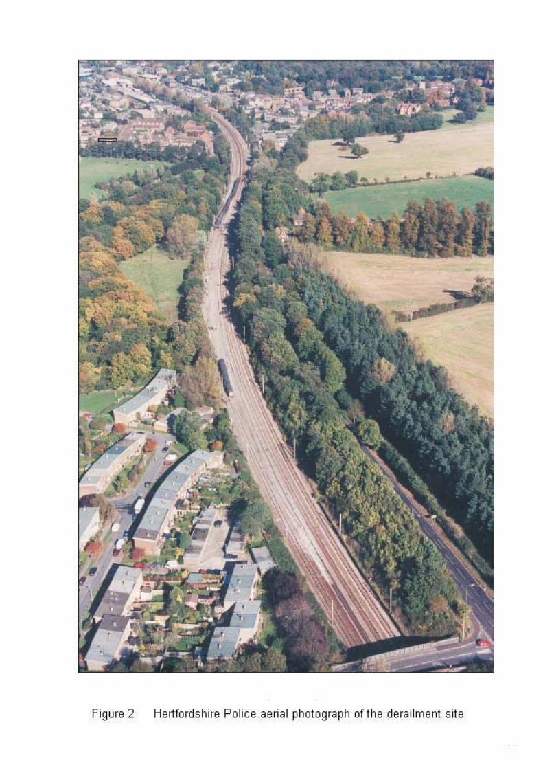

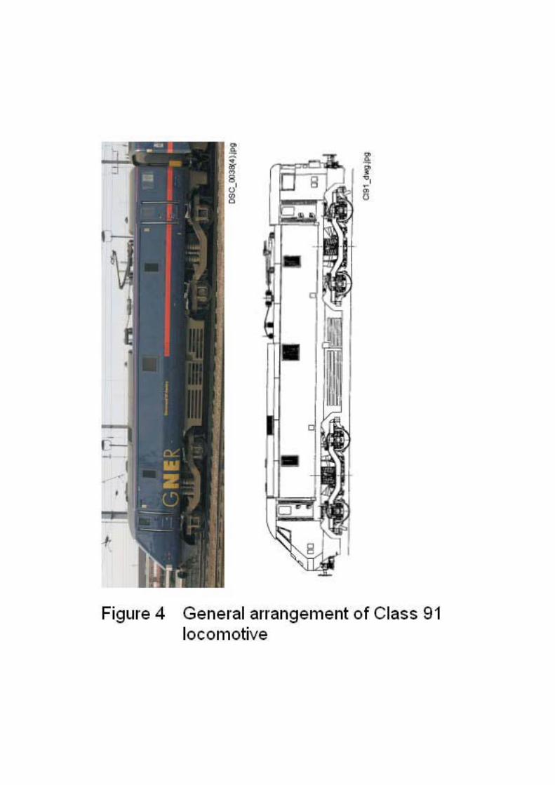


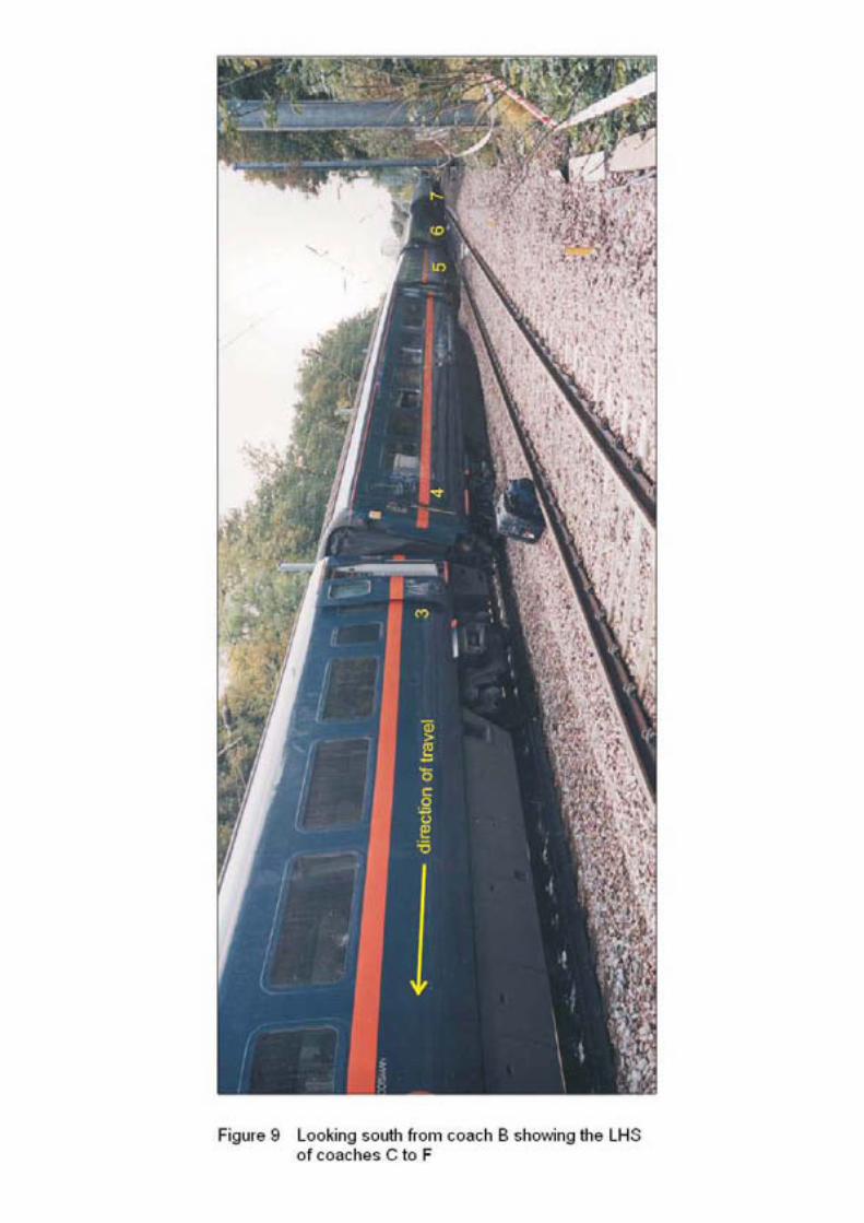
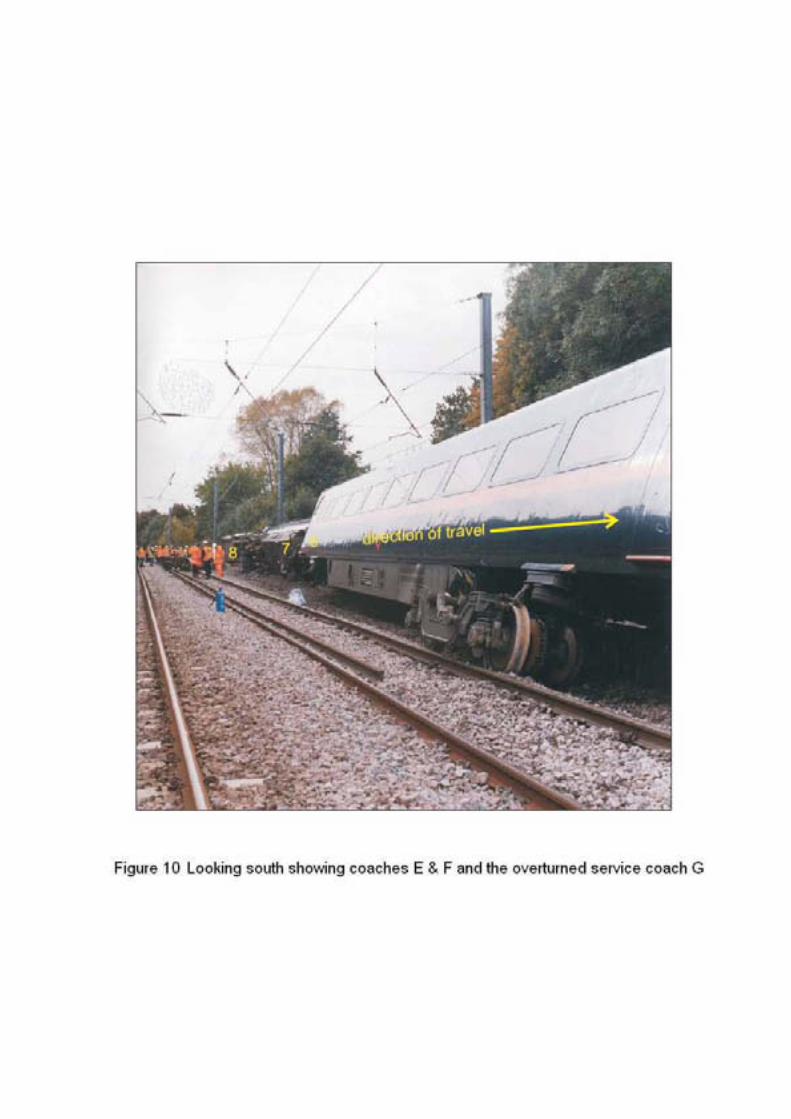


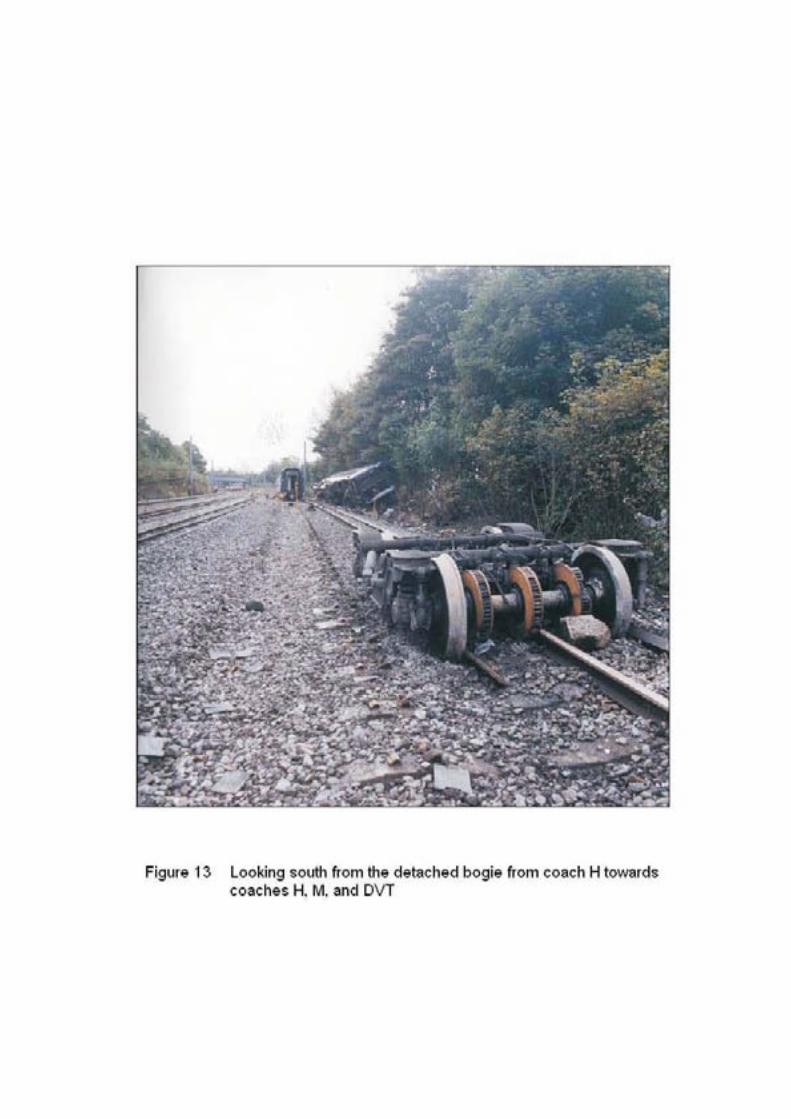

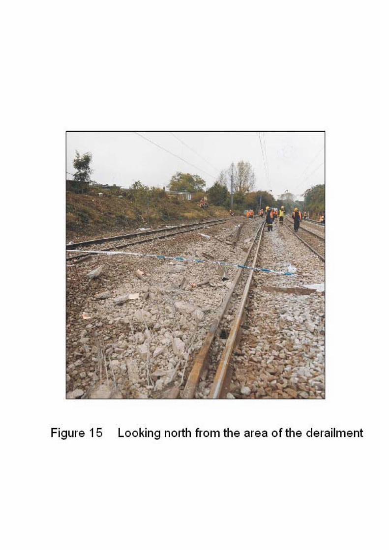


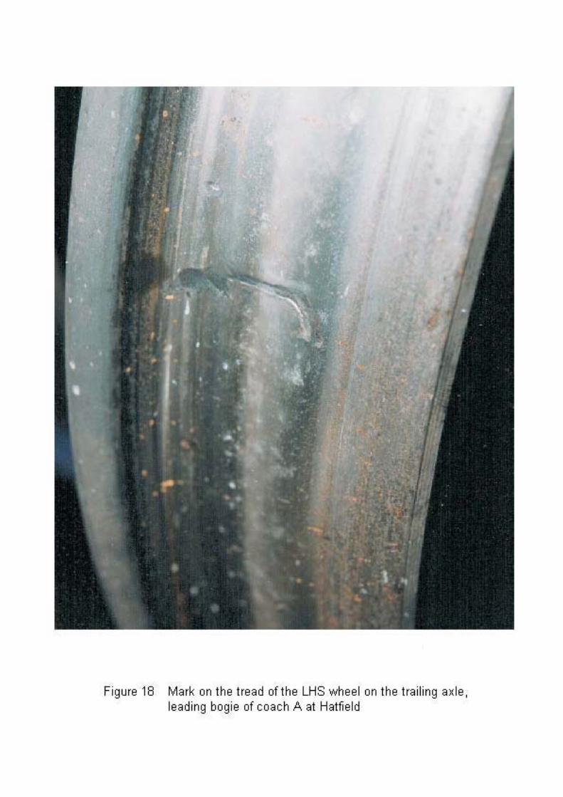
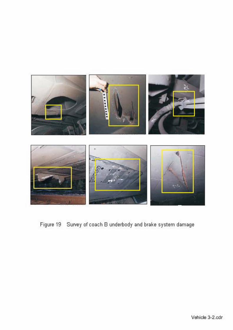


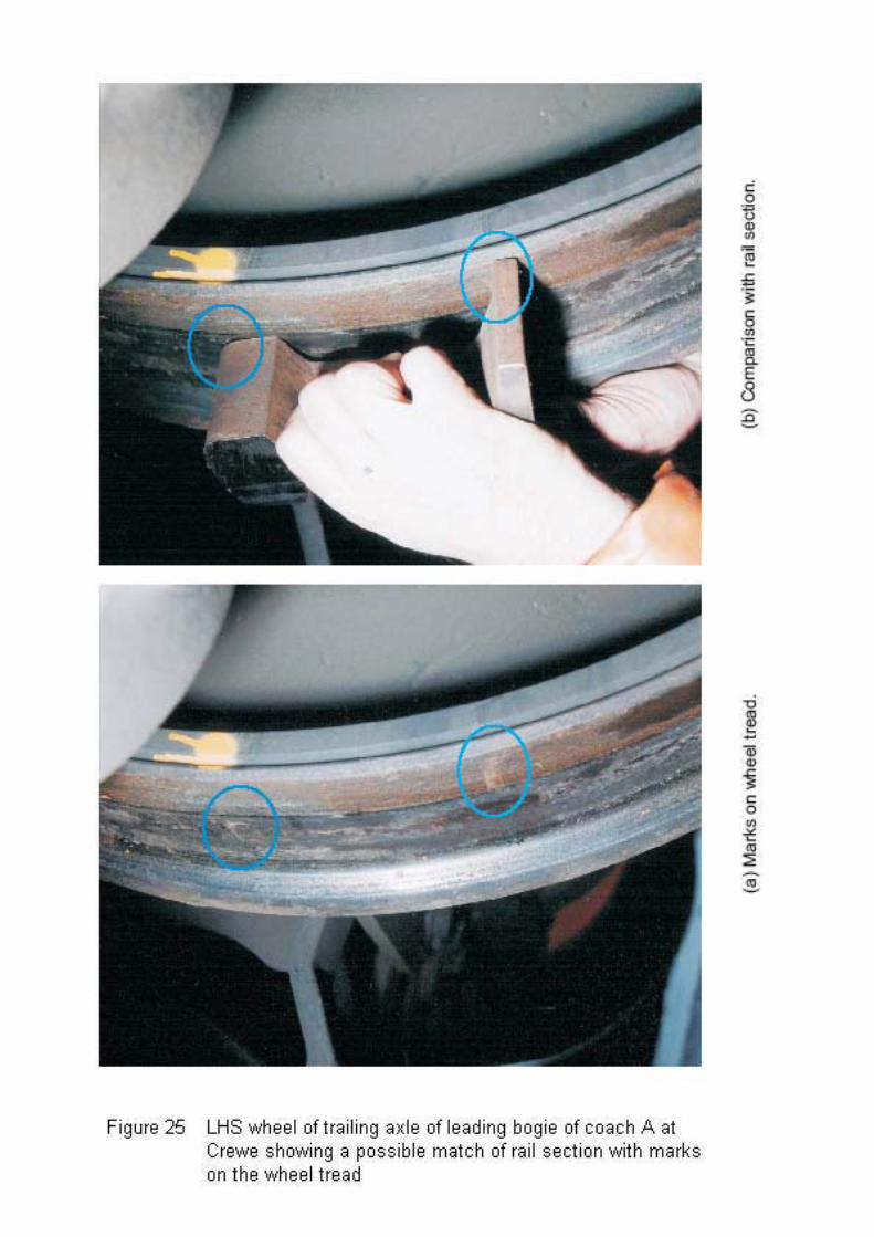
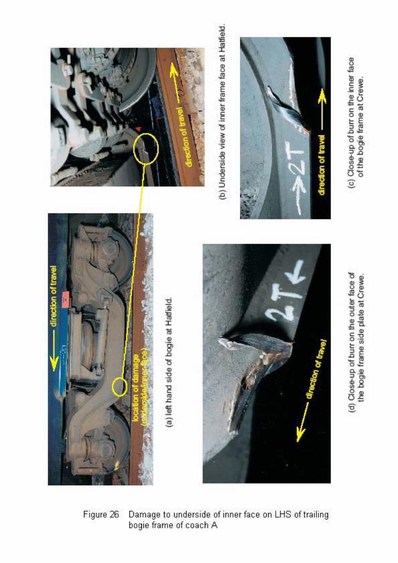


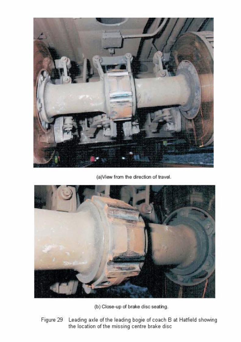

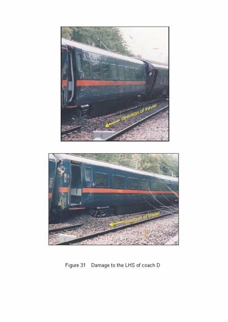


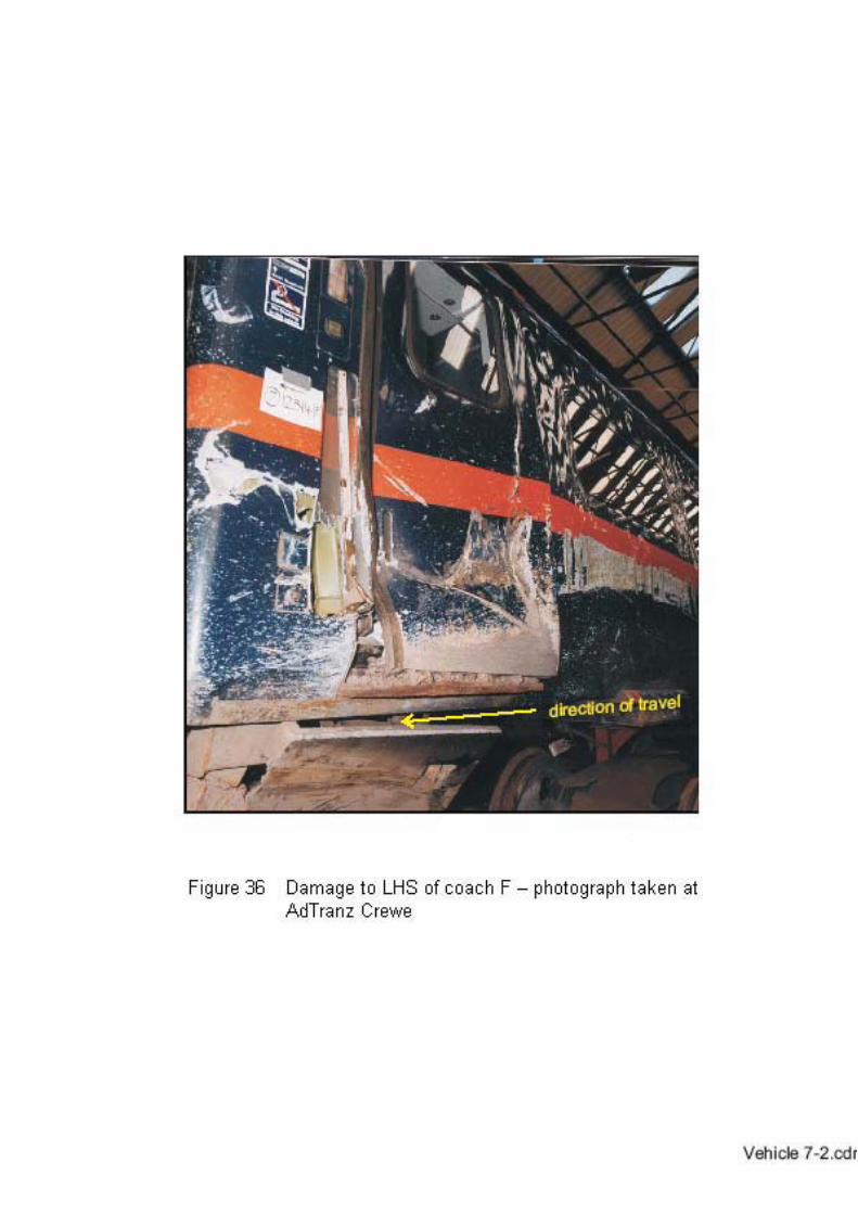
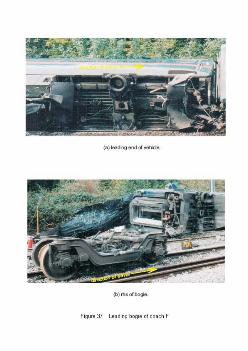


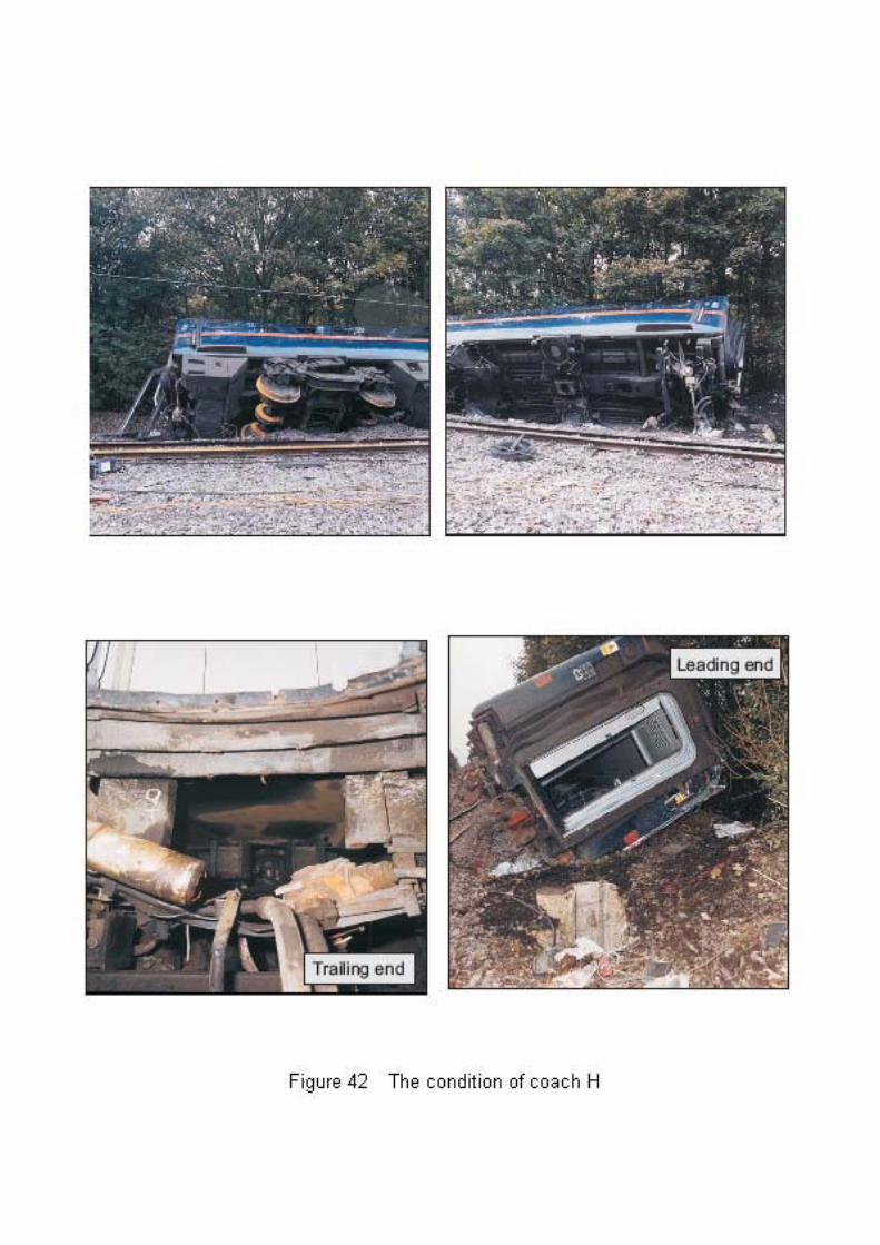
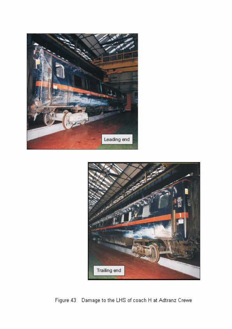
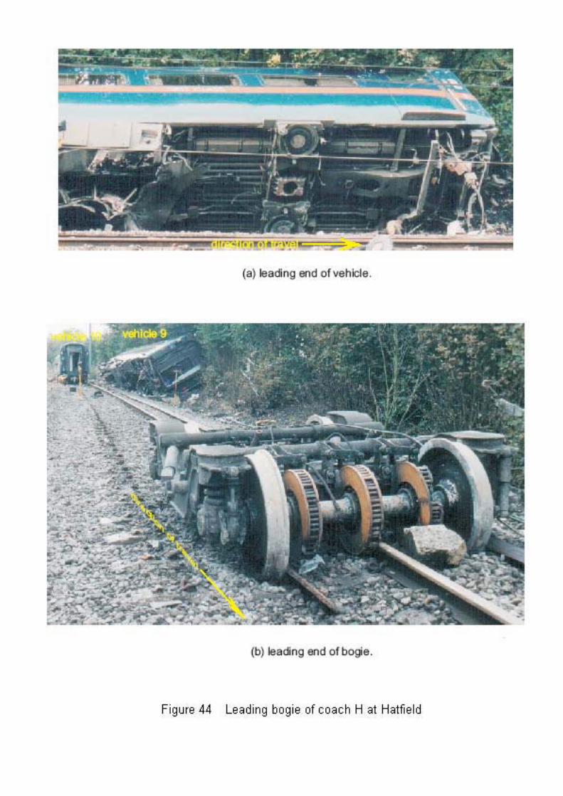


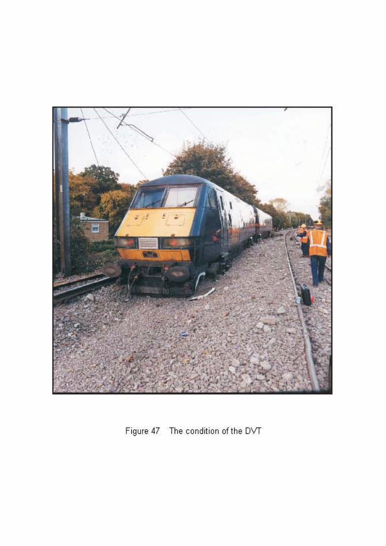
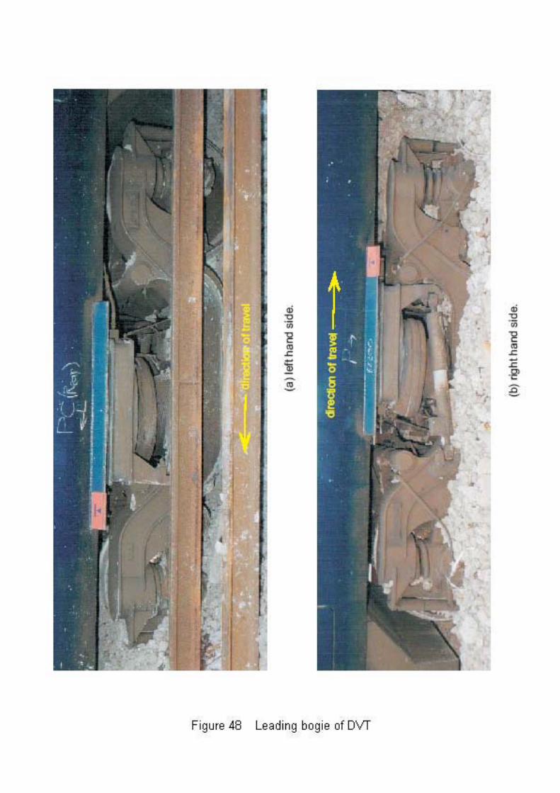
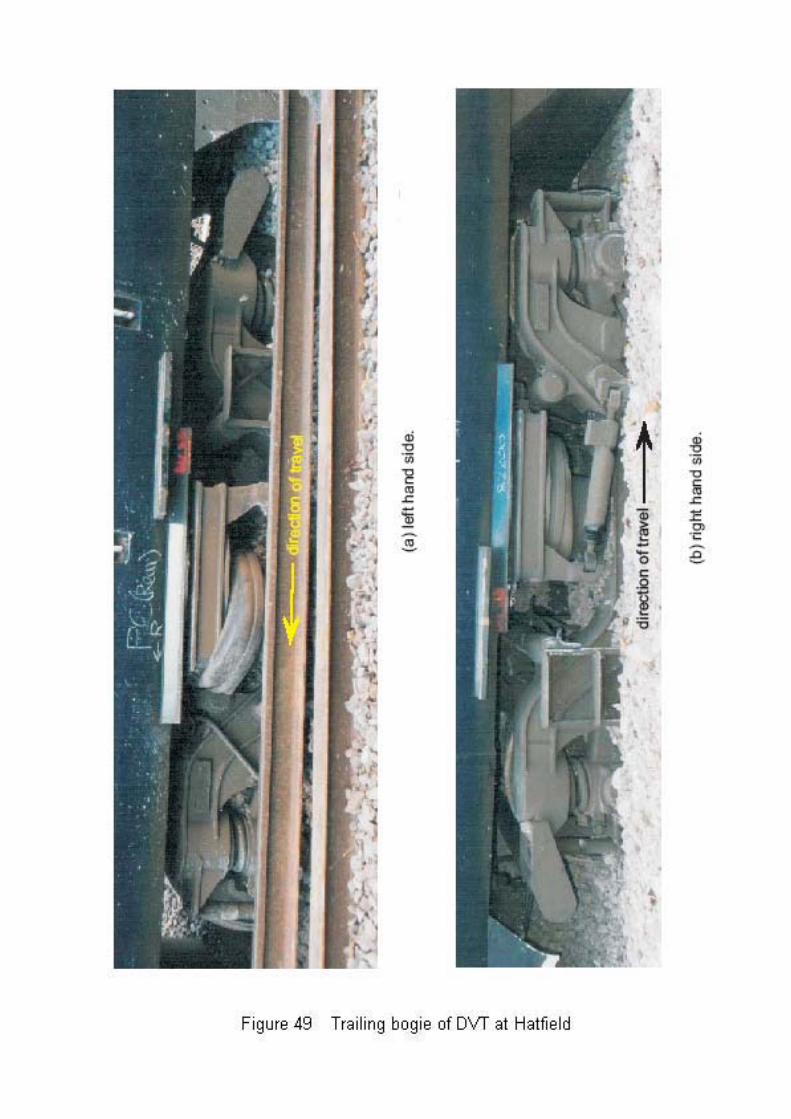

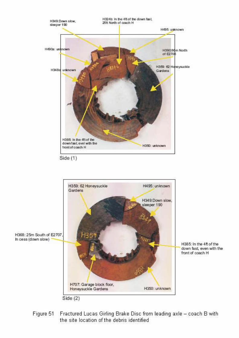

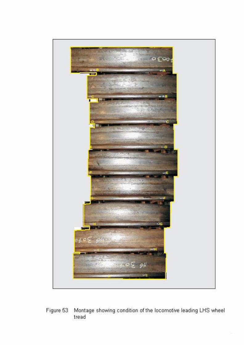

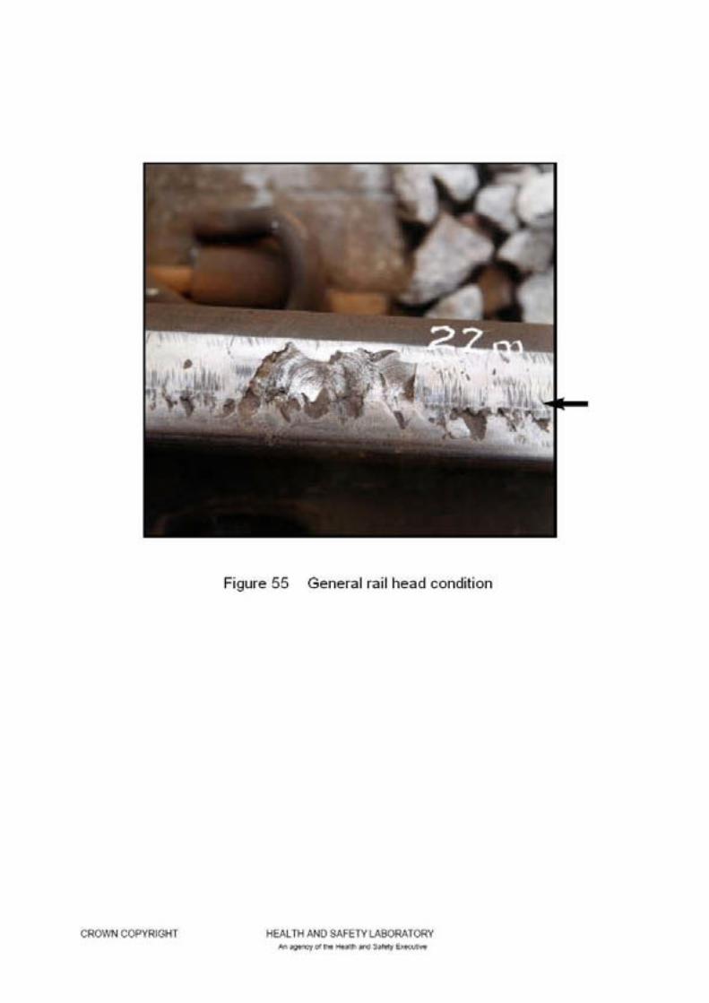
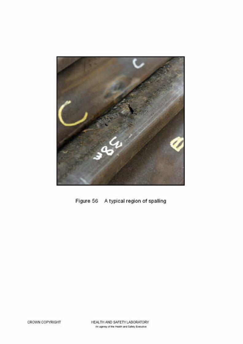


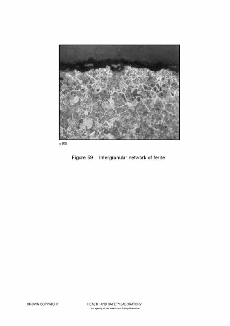

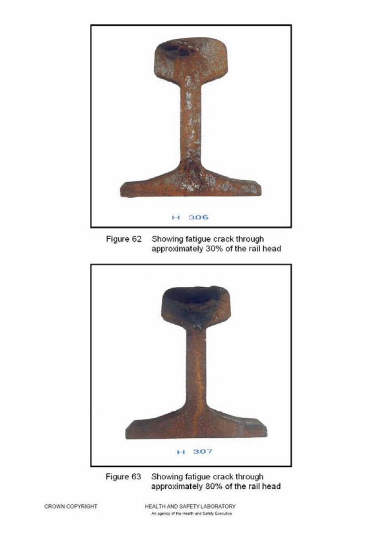
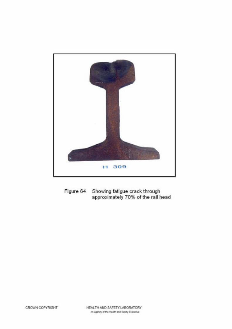
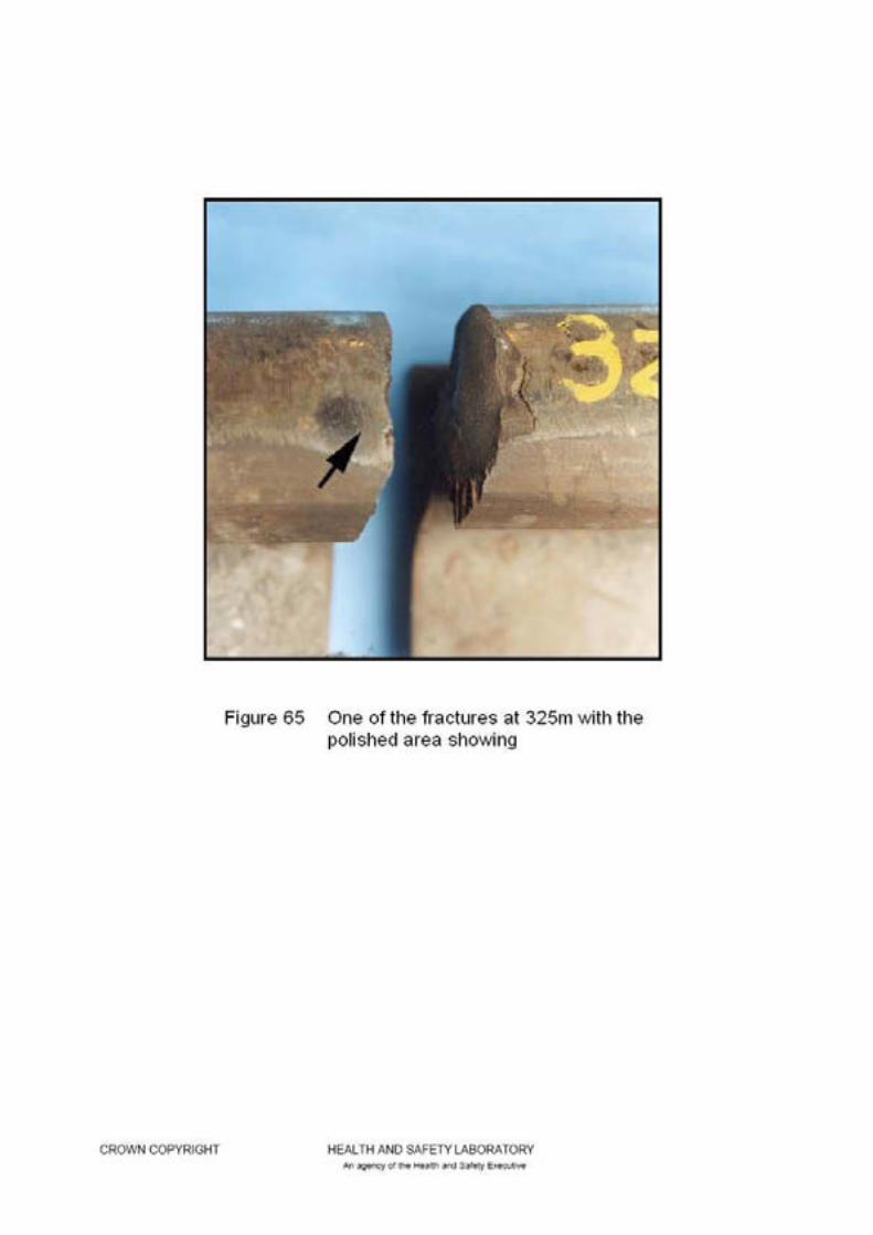

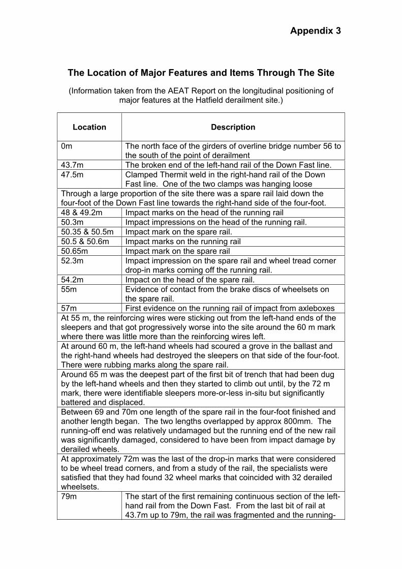
Appendix 3
The Location of Major Features and Items Through The Site
(Information taken from the AEAT Report on the longitudinal positioning of major features at the Hatfield derailment site.)
Location Description
0m The north face of the girders of overline bridge number 56 to the south of the point of derailment
43.7m The broken end of the left-hand rail of the Down Fast line.
47.5m Clamped Thermit weld in the right-hand rail of the Down Fast line. One of the two clamps was hanging loose
Through a large proportion of the site there was a spare rail laid down the four-foot of the Down Fast line towards the right-hand side of the four-foot.
48 & 49.2m Impact marks on the head of the running rail
50.3m Impact impressions on the head of the running rail.
50.35 & 50.5m Impact mark on the spare rail.
50.5 & 50.6m Impact marks on the running rail
50.65m Impact mark on the spare rail
52.3m Impact impression on the spare rail and wheel tread corner drop-in marks coming off the running rail.
54.2m Impact on the head of the spare rail.
55m Evidence of contact from the brake discs of wheelsets on the spare rail.
57m First evidence on the running rail of impact from axleboxes
At 55 m, the reinforcing wires were sticking out from the left-hand ends of the sleepers and that got progressively worse into the site around the 60 m mark where there was little more than the reinforcing wires left.
At around 60 m, the left-hand wheels had scoured a grove in the ballast and the right-hand wheels had destroyed the sleepers on that side of the four-foot.There were rubbing marks along the spare rail.
Around 65 m was the deepest part of the first bit of trench that had been dug by the left-hand wheels and then they started to climb out until, by the 72 m mark, there were identifiable sleepers more-or-less in-situ but significantly battered and displaced.
Between 69 and 70m one length of the spare rail in the four-foot finished and another length began. The two lengths overlapped by approx 800mm. The running-off end was relatively undamaged but the running end of the new rail was significantly damaged, considered to have been from impact damage by derailed wheels.
At approximately 72m was the last of the drop-in marks that were considered to be wheel tread corners, and from a study of the rail, the specialists were satisfied that they had found 32 wheel marks that coincided with 32 derailed wheelsets.
79m The start of the first remaining continuous section of the left-hand rail from the Down Fast. From the last bit of rail at 43.7m up to 79m, the rail was fragmented and the running-
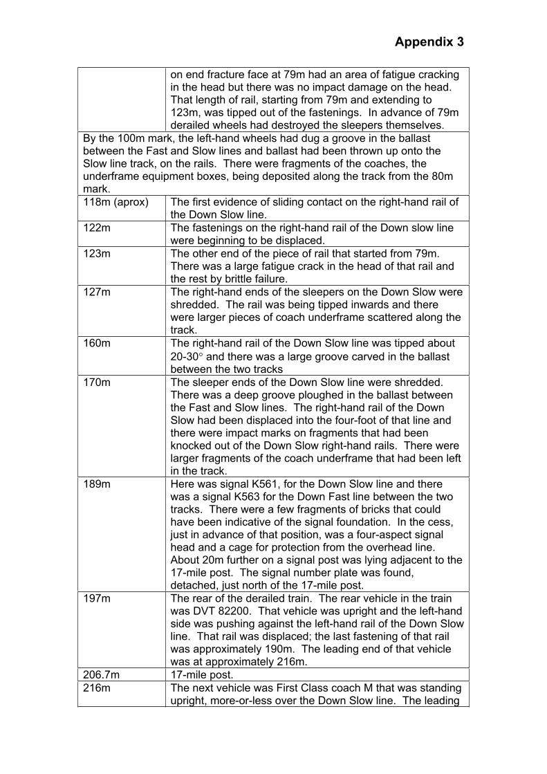
Appendix 3
on end fracture face at 79m had an area of fatigue cracking in the head but there was no impact damage on the head.That length of rail, starting from 79m and extending to 123m, was tipped out of the fastenings. In advance of 79m derailed wheels had destroyed the sleepers themselves.
By the 100m mark, the left-hand wheels had dug a groove in the ballast between the Fast and Slow lines and ballast had been thrown up onto the Slow line track, on the rails. There were fragments of the coaches, the underframe equipment boxes, being deposited along the track from the 80m mark.
118m (aprox) The first evidence of sliding contact on the right-hand rail of the Down Slow line.
122m The fastenings on the right-hand rail of the Down slow line were beginning to be displaced.
123m The other end of the piece of rail that started from 79m.There was a large fatigue crack in the head of that rail and the rest by brittle failure.
127m The right-hand ends of the sleepers on the Down Slow were shredded. The rail was being tipped inwards and there were larger pieces of coach underframe scattered along the track.
160m The right-hand rail of the Down Slow line was tipped about
20-30 and there was a large groove carved in the ballast between the two tracks
170m The sleeper ends of the Down Slow line were shredded.There was a deep groove ploughed in the ballast between the Fast and Slow lines. The right-hand rail of the Down Slow had been displaced into the four-foot of that line and there were impact marks on fragments that had been knocked out of the Down Slow right-hand rails. There were larger fragments of the coach underframe that had been left in the track.
189m Here was signal K561, for the Down Slow line and there was a signal K563 for the Down Fast line between the two tracks. There were a few fragments of bricks that could have been indicative of the signal foundation. In the cess, just in advance of that position, was a four-aspect signal head and a cage for protection from the overhead line.About 20m further on a signal post was lying adjacent to the 17-mile post. The signal number plate was found, detached, just north of the 17-mile post.
197m The rear of the derailed train. The rear vehicle in the train was DVT 82200. That vehicle was upright and the left-hand side was pushing against the left-hand rail of the Down Slow line. That rail was displaced; the last fastening of that rail was approximately 190m. The leading end of that vehicle was at approximately 216m.
206.7m 17-mile post.
216m The next vehicle was First Class coach M that was standing upright, more-or-less over the Down Slow line. The leading

Appendix 3
bogie was displaced laterally and was intact, the trailing bogie intact and in-situ. There was a gap about 5m between that vehicle and the one in front of it.
The preceding vehicle was First Class coach H. That was leaning at about
50 to the left into the bushes to the left of the Down Slow line. The trailing bogie was in-situ but somewhat displaced, hanging on by its yaw dampers.The leading bogie was displaced and appeared to have gone on ahead.
There was an upturned rail to the cess side of the cess rail of the Down Slow line. This was the right-hand rail from that line.
266m The front of coach H. Immediately in front of the leading end of that coach, on the cess of the Down Slow line, were the remains of a concrete foundation for an OLE mast, almost in line with the corridor connection. That was one of the masts for the headspan equipment at location E27/08.The mast was displaced. There was then a gap between the vehicle and the front portion of the train.
293m A detached coach bogie, serial number 5419, possibly the leading bogie of coach H.
320-330m At around the 325m mark there were two fractures in the left-hand rail of the Down Fast line. One had a large fatigue crack area on the head, followed by vertical brittle failure through the web and foot. There was rust on the fracture face but the age was indeterminate owing to the length of time between the derailment of the train and the examination. There was another break, about 2m further on, where the whole rail was cracked through. At both of these rail breaks there was evidence on the running-on end of the fracture face that wheels had run over that fracture after failure.
336m The foundation in the Down Slow cess side for the next OLE mast E27/09. The mast was displaced.
363m A bogie outside the railway boundary, down the embankment to the left.
393m One of the OLE masts, carrying the number E27/09, lying across the tracks
402m Overhead line structure number E27/10, leaning at a slight angle to the north.
419m Mast from overhead line structure, unnumbered, presumed from E27/08, lying across the tracks. Ahead of that point, there were various items of debris and some coach seats between there and the next overhead line structure that was E27/11.
455-456m Another break of the left-hand rail of the Down Fast.
470m Overhead line structure 27/11
507m Trailer bogie 5263 straddling the left-hand rail of the Down Fast
511m The trailing end of the service coach G, the roof splayed out behind it. This was the trailing corridor connection end.
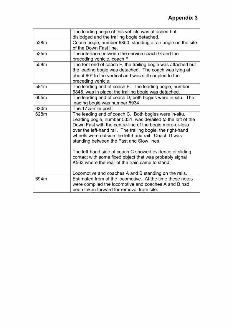
Appendix 3
The leading bogie of this vehicle was attached but dislodged and the trailing bogie detached.
528m Coach bogie, number 6850, standing at an angle on the site of the Down Fast line.
535m The interface between the service coach G and the preceding vehicle, coach F.
558m The font end of coach F, the trailing bogie was attached but the leading bogie was detached. The coach was lying at
about 60 to the vertical and was still coupled to the preceding vehicle.
581m The leading end of coach E. The leading bogie, number 6845, was in place; the trailing bogie was detached.
605m The leading end of coach D, both bogies were in-situ. The leading bogie was number 5934.
620m The 17¼-mile post.
628m The leading end of coach C. Both bogies were in-situ.Leading bogie, number 5331, was derailed to the left of the Down Fast with the centre-line of the bogie more-or-less over the left-hand rail. The trailing bogie, the right-hand wheels were outside the left-hand rail. Coach D was standing between the Fast and Slow lines.
The left-hand side of coach C showed evidence of sliding contact with some fixed object that was probably signal K563 where the rear of the train came to stand.
Locomotive and coaches A and B standing on the rails.
694m Estimated from of the locomotive. At the time these notes were compiled the locomotive and coaches A and B had been taken forward for removal from site.
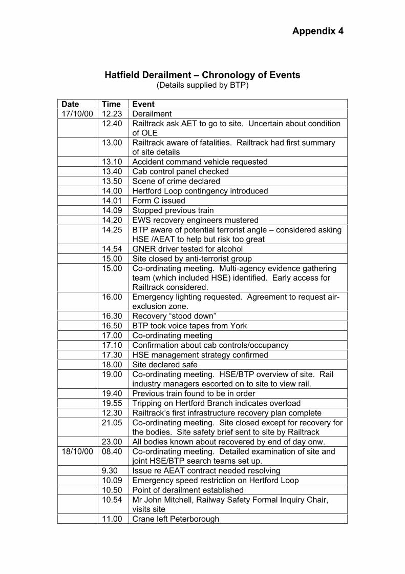
Appendix 4
Hatfield Derailment – Chronology of Events (Details supplied by BTP)
Date Time Event
17/10/00 12.23 Derailment
12.40 Railtrack ask AET to go to site. Uncertain about condition of OLE
13.00 Railtrack aware of fatalities. Railtrack had first summary of site details
13.10 Accident command vehicle requested
13.40 Cab control panel checked
13.50 Scene of crime declared
14.00 Hertford Loop contingency introduced
14.01 Form C issued
14.09 Stopped previous train
14.20 EWS recovery engineers mustered
14.25 BTP aware of potential terrorist angle – considered asking HSE /AEAT to help but risk too great
14.54 GNER driver tested for alcohol
15.00 Site closed by anti-terrorist group
15.00 Co-ordinating meeting. Multi-agency evidence gathering team (which included HSE) identified. Early access for Railtrack considered.
16.00 Emergency lighting requested. Agreement to request air-exclusion zone.
16.30 Recovery “stood down”
16.50 BTP took voice tapes from York
17.00 Co-ordinating meeting
17.10 Confirmation about cab controls/occupancy
17.30 HSE management strategy confirmed
18.00 Site declared safe
19.00 Co-ordinating meeting. HSE/BTP overview of site. Rail industry managers escorted on to site to view rail.
19.40 Previous train found to be in order
19.55 Tripping on Hertford Branch indicates overload
12.30 Railtrack’s first infrastructure recovery plan complete
21.05 Co-ordinating meeting. Site closed except for recovery for the bodies. Site safety brief sent to site by Railtrack
23.00 All bodies known about recovered by end of day onw.
18/10/00 08.40 Co-ordinating meeting. Detailed examination of site and joint HSE/BTP search teams set up.
9.30 Issue re AEAT contract needed resolving
10.09 Emergency speed restriction on Hertford Loop
10.50 Point of derailment established
10.54 Mr John Mitchell, Railway Safety Formal Inquiry Chair, visits site
11.00 Crane left Peterborough
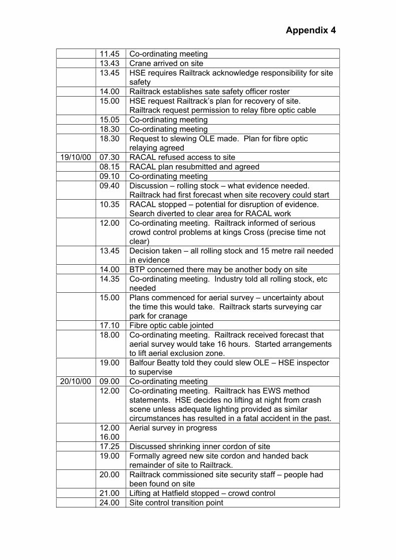
Appendix 4
11.45 Co-ordinating meeting
13.43 Crane arrived on site
13.45 HSE requires Railtrack acknowledge responsibility for site safety
14.00 Railtrack establishes sate safety officer roster
15.00 HSE request Railtrack’s plan for recovery of site.Railtrack request permission to relay fibre optic cable
15.05 Co-ordinating meeting
18.30 Co-ordinating meeting
18.30 Request to slewing OLE made. Plan for fibre optic relaying agreed
19/10/00 07.30 RACAL refused access to site
08.15 RACAL plan resubmitted and agreed
09.10 Co-ordinating meeting
09.40 Discussion – rolling stock – what evidence needed.Railtrack had first forecast when site recovery could start
10.35 RACAL stopped – potential for disruption of evidence. Search diverted to clear area for RACAL work
12.00 Co-ordinating meeting. Railtrack informed of serious crowd control problems at kings Cross (precise time not clear)
13.45 Decision taken – all rolling stock and 15 metre rail needed in evidence
14.00 BTP concerned there may be another body on site
14.35 Co-ordinating meeting. Industry told all rolling stock, etc needed
15.00 Plans commenced for aerial survey – uncertainty about the time this would take. Railtrack starts surveying car park for cranage
17.10 Fibre optic cable jointed
18.00 Co-ordinating meeting. Railtrack received forecast that aerial survey would take 16 hours. Started arrangements to lift aerial exclusion zone.
19.00 Balfour Beatty told they could slew OLE – HSE inspector to supervise
20/10/00 09.00 Co-ordinating meeting
12.00 Co-ordinating meeting. Railtrack has EWS method statements. HSE decides no lifting at night from crash scene unless adequate lighting provided as similar circumstances has resulted in a fatal accident in the past.
12.00 16.00
Aerial survey in progress
17.25 Discussed shrinking inner cordon of site
19.00 Formally agreed new site cordon and handed back remainder of site to Railtrack.
20.00 Railtrack commissioned site security staff – people had been found on site
21.00 Lifting at Hatfield stopped – crowd control
24.00 Site control transition point
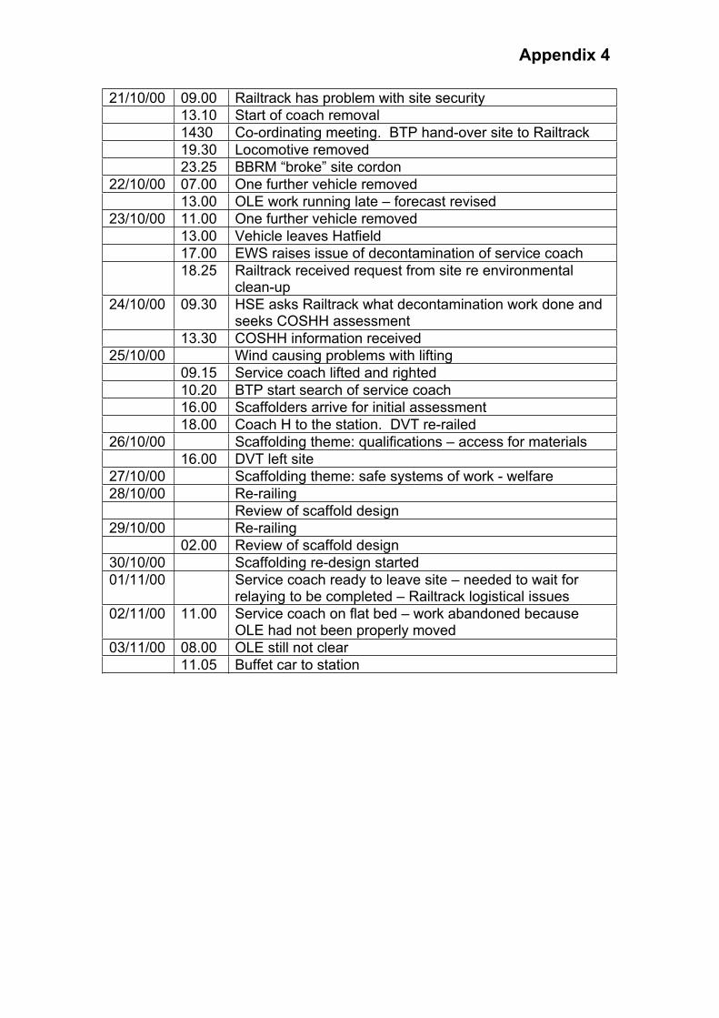
Appendix 4
21/10/00 09.00 Railtrack has problem with site security
13.10 Start of coach removal
1430 Co-ordinating meeting. BTP hand-over site to Railtrack
19.30 Locomotive removed
23.25 BBRM “broke” site cordon
22/10/00 07.00 One further vehicle removed
13.00 OLE work running late – forecast revised
23/10/00 11.00 One further vehicle removed
13.00 Vehicle leaves Hatfield
17.00 EWS raises issue of decontamination of service coach
18.25 Railtrack received request from site re environmental clean-up
24/10/00 09.30 HSE asks Railtrack what decontamination work done and seeks COSHH assessment
13.30 COSHH information received
25/10/00 Wind causing problems with lifting
09.15 Service coach lifted and righted
10.20 BTP start search of service coach
16.00 Scaffolders arrive for initial assessment
18.00 Coach H to the station. DVT re-railed
26/10/00 Scaffolding theme: qualifications – access for materials
16.00 DVT left site
27/10/00 Scaffolding theme: safe systems of work - welfare
28/10/00 Re-railing
Review of scaffold design
29/10/00 Re-railing
02.00 Review of scaffold design
30/10/00 Scaffolding re-design started
01/11/00 Service coach ready to leave site – needed to wait for relaying to be completed – Railtrack logistical issues
02/11/00 11.00 Service coach on flat bed – work abandoned because OLE had not been properly moved
03/11/00 08.00 OLE still not clear
11.05 Buffet car to station
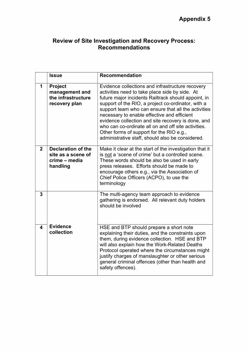
Appendix 5
Review of Site Investigation and Recovery Process: Recommendations
Issue Recommendation
1 Project management and the infrastructure recovery plan
Evidence collections and infrastructure recovery activities need to take place side by side. At future major incidents Railtrack should appoint, in support of the RIO, a project co-ordinator, with a support team who can ensure that all the activities necessary to enable effective and efficient evidence collection and site recovery is done, and who can co-ordinate all on and off site activities.Other forms of support for the RIO e.g., administrative staff, should also be considered.
2 Declaration of the site as a scene of crime – media handling
Make it clear at the start of the investigation that it is not a ‘scene of crime’ but a controlled scene.These words should be also be used in early press releases. Efforts should be made to encourage others e.g., via the Association of Chief Police Officers (ACPO), to use the terminology
3 The multi-agency team approach to evidence gathering is endorsed. All relevant duty holders should be involved
4 Evidencecollection
HSE and BTP should prepare a short note explaining their duties, and the constraints upon them, during evidence collection. HSE and BTP will also explain how the Work-Related Deaths Protocol operated where the circumstances might justify charges of manslaughter or other serious general criminal offences (other than health and safety offences).

Appendix 5
5 Administrative support should be employed to ensue information shared at communication meetings is recorded and distributed. Important decisions about proposed activities on site should be taken at communication meetings to ensure effective communication and implementation
6
Clarity of relationships;communications;roles and responsibilities,especially site safety issues
Railtrack should consider how best to educate the industry and emergency services about responsibilities for site safety. This should include how those duties can be effectively discharged, on a properly co-ordinated basis, given the rapidly changing environment that exists during incidents of this kind.
7 Appointment of specialistcontractors
All specialist contractors should have a full job specification that should be made available to all interested parties
8 Fibre optic cable and safety critical services
All information on reasons for safety critical work must be communicated clearly to avoid confusion and delay
9 Night working and night lifting
There must be clear communication of exactly what is expected of duty holders. HSE requires safe systems of work and is open to approaches from duty holders during investigations on how this might be achieved.
10 Re-opening of adjacent lines
This reinforces the need for an integrated approach to evidence collections and reinstatement, to ensure maximum efficiency and minimisation of delay.
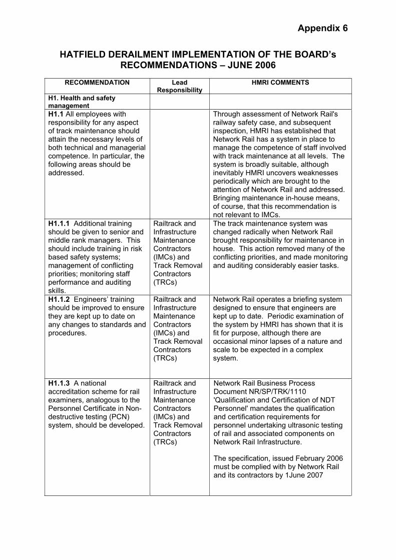
Appendix 6
HATFIELD DERAILMENT IMPLEMENTATION OF THE BOARD’s RECOMMENDATIONS – JUNE 2006
RECOMMENDATION Lead Responsibility
HMRI COMMENTS
H1. Health and safety management
H1.1 All employees with responsibility for any aspect of track maintenance should attain the necessary levels of both technical and managerial competence. In particular, the following areas should be addressed.
Through assessment of Network Rail's railway safety case, and subsequent inspection, HMRI has established that Network Rail has a system in place to manage the competence of staff involved with track maintenance at all levels. The system is broadly suitable, although inevitably HMRI uncovers weaknesses periodically which are brought to the attention of Network Rail and addressed. Bringing maintenance in-house means, of course, that this recommendation is not relevant to IMCs.
H1.1.1 Additional training should be given to senior and middle rank managers. This should include training in risk based safety systems; management of conflicting priorities; monitoring staff performance and auditing skills.
Railtrack and Infrastructure MaintenanceContractors(IMCs) and Track Removal Contractors(TRCs)
The track maintenance system was changed radically when Network Rail brought responsibility for maintenance in house. This action removed many of the conflicting priorities, and made monitoring and auditing considerably easier tasks.
H1.1.2 Engineers’ training should be improved to ensure they are kept up to date on any changes to standards and procedures.
Railtrack and Infrastructure MaintenanceContractors(IMCs) and Track Removal Contractors(TRCs)
Network Rail operates a briefing system designed to ensure that engineers are kept up to date. Periodic examination of the system by HMRI has shown that it is fit for purpose, although there are occasional minor lapses of a nature and scale to be expected in a complex system.
H1.1.3 A national accreditation scheme for rail examiners, analogous to the Personnel Certificate in Non-destructive testing (PCN) system, should be developed.
Railtrack and Infrastructure MaintenanceContractors(IMCs) and Track Removal Contractors(TRCs)
Network Rail Business Process Document NR/SP/TRK/1110 'Qualification and Certification of NDT Personnel' mandates the qualification and certification requirements for personnel undertaking ultrasonic testing of rail and associated components on Network Rail Infrastructure.
The specification, issued February 2006 must be complied with by Network Rail and its contractors by 1June 2007
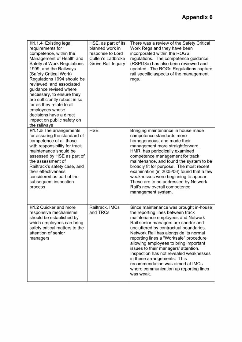
Appendix 6
H1.1.4 Existing legal requirements for competence, within the Management of Health and Safety at Work Regulations 1999, and the Railways (Safety Critical Work) Regulations 1994 should be reviewed, and associated guidance revised where necessary, to ensure they are sufficiently robust in so far as they relate to all employees whose decisions have a direct impact on public safety on the railways
HSE, as part of its planned work in response to Lord Cullen’s Ladbroke Grove Rail Inquiry
There was a review of the Safety Critical Work Regs and they have been incorporated within the ROGS regulations. The competence guidance (RSPG3a) has also been reviewed and updated. The ROGs Regulations capture rail specific aspects of the management regs.
H1.1.5 The arrangements for assuring the standard of competence of all those with responsibility for track maintenance should be assessed by HSE as part of the assessment of Railtrack’s safety case, and their effectiveness considered as part of the subsequent inspection process
HSE Bringing maintenance in house made competence standards more homogeneous, and made their management more straightforward. HMRI has periodically examined competence management for track maintenance, and found the system to be broadly fit for purpose. The most recent examination (in 2005/06) found that a few weaknesses were beginning to appear. These are to be addressed by Network Rail's new overall competence management system.
H1.2 Quicker and more responsive mechanisms should be established by which employees can bring safety critical matters to the attention of senior managers
Railtrack, IMCs and TRCs
Since maintenance was brought in-house the reporting lines between track maintenance employees and Network Rail senior managers are shorter and uncluttered by contractual boundaries. Network Rail has alongside its normal reporting lines a "Worksafe" procedure allowing employees to bring important issues to their managers' attention. Inspection has not revealed weaknesses in these arrangements. This recommendation was aimed at IMCs where communication up reporting lines was weak.
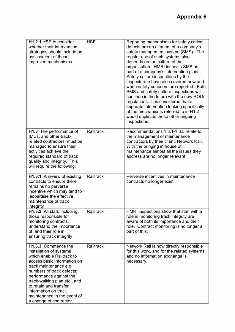
Appendix 6
H1.2.1 HSE to consider whether their intervention strategies should include an assessment of these improved mechanisms.
HSE Reporting mechanisms for safety critical defects are an element of a company’s safety management system (SMS). The regular use of such systems also depends on the culture of the organisation. HMRI inspects SMS as part of a company’s intervention plans. Safety culture inspections by the inspectorate have also covered how and when safety concerns are reported. Both SMS and safety culture inspections will continue in the future with the new ROGs regulations. It is considered that a separate intervention looking specifically at the mechanisms referred to in H1.2 would duplicate these other ongoing inspections.
H1.3 The performance of IMCs, and other track-related contractors, must be managed to ensure their activities achieve the required standard of track quality and integrity. This will require the following:
Railtrack Recommendations 1.3.1-1.3.5 relate to the management of maintenance contractors by their client, Network Rail. With the bringing in house of maintenance almost all the issues they address are no longer relevant.
H1.3.1 A review of existing contracts to ensure there remains no perverse incentive which may tend to jeopardise the effective maintenance of track integrity
Railtrack Perverse incentives in maintenance contracts no longer exist.
H1.3.2 All staff, including those responsible for monitoring contracts, understand the importance of, and their role in, ensuring track integrity
Railtrack HMRI inspections show that staff with a role in monitoring track integrity are aware of both its importance and their role. Contract monitoring is no longer a part of this.
H1.3.3 Commence the installation of systems which enable Railtrack to access basic information on track maintenance e.g. numbers of track defects; performance against the track-walking plan etc., and to retain and transfer information on track maintenance in the event of a change of contractor.
Railtrack Network Rail is now directly responsible for this work, and for the related systems, and no information exchange is necessary.
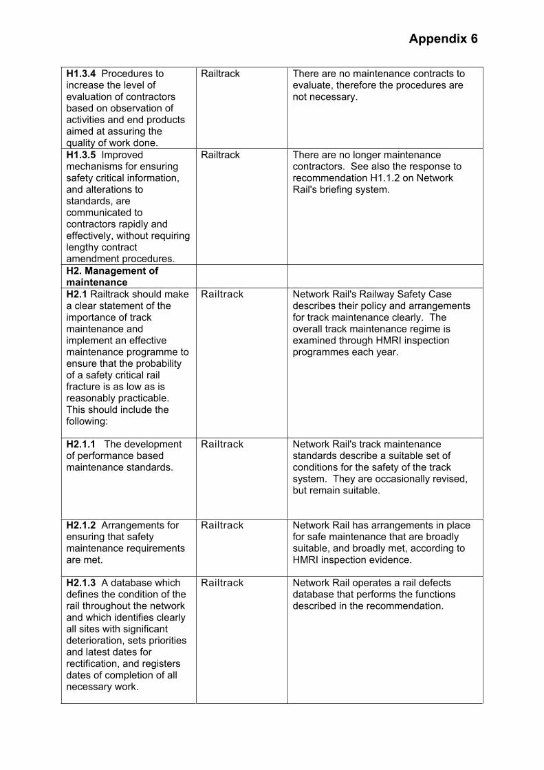
Appendix 6
H1.3.4 Procedures to increase the level of evaluation of contractors based on observation of activities and end products aimed at assuring the quality of work done.
Railtrack There are no maintenance contracts to evaluate, therefore the procedures are not necessary.
H1.3.5 Improved mechanisms for ensuring safety critical information, and alterations to standards, are communicated to contractors rapidly and effectively, without requiring lengthy contract amendment procedures.
Railtrack There are no longer maintenance contractors. See also the response to recommendation H1.1.2 on Network Rail's briefing system.
H2. Management of maintenance
H2.1 Railtrack should make a clear statement of the importance of track maintenance and implement an effective maintenance programme to ensure that the probability of a safety critical rail fracture is as low as is reasonably practicable. This should include the following:
Railtrack Network Rail's Railway Safety Case describes their policy and arrangements for track maintenance clearly. The overall track maintenance regime is examined through HMRI inspection programmes each year.
H2.1.1 The development of performance based maintenance standards.
Railtrack Network Rail's track maintenance standards describe a suitable set of conditions for the safety of the track system. They are occasionally revised, but remain suitable.
H2.1.2 Arrangements for ensuring that safety maintenance requirements are met.
Railtrack Network Rail has arrangements in place for safe maintenance that are broadly suitable, and broadly met, according to HMRI inspection evidence.
H2.1.3 A database which defines the condition of the rail throughout the network and which identifies clearly all sites with significant deterioration, sets priorities and latest dates for rectification, and registers dates of completion of all necessary work.
Railtrack Network Rail operates a rail defects database that performs the functions described in the recommendation.

Appendix 6
H2.1.4 A revised strategy, developed in conjunction with rail manufacturers, train operating companies (TOCs), rolling stock companies (ROSCOs), and IMCs for proactively managing all aspects of identification and rectification of rail deterioration. Any changes to existing practice should be incorporated into relevant contracts with manufacturers and IMCs.
Railtrack The most recent Network Rail Technical Plan - 2004, includes at Section 9 the companies Asset Stewardship Strategy for Track. This recognises that “Track assets comprise a complex system and deterioration of individual components has an adverse effect on the others...... and that, degradation of track is mainly due to the volume and type of traffic that runs over it, resulting in two degradation mechanisms; wear and fatigue.” An increase in network traffic and recently introduced rolling stock that imparts greater forces on the track contributes to track degradation rates. Similarly an inadequate inspection and maintenance regime will increase the degradation rate. Network Rail's policy therefore operates on a number of fronts in seeking to minimise the factors that contribute to track degradation rates thereby maximising the safe serviceable life of the track asset. These include: new and innovative inspection techniques allowing a more proactive maintenance regime to be introduced. For example introduction of new technology on the New Maintenance Train providing detailed track geometry measurements on a high-speed train, operating within the timetable of existing services. In addition the introduction of Unattended Geometry Measurement Systems on TOC service trains provides improved objective measures of track condition - allowing a move towards the Measure, Predict and Prevent philosophy of proactive maintenance as opposed to the traditional reactive correction of defects found.
Vehicle condition - Monitoring wheel impact loads using Wheelchex, the results of which are passed to the TOC's who use it to manage their wheelset condition - thereby reducing the adverse forces imparted onto the track.
Managing Rolling Contact Fatigue, - explained in detail in other parts of this review of recommendations.
Managing the Wheel Rail Interface.Vehicle characteristics have been identified as a significant factor in rail

Appendix 6
deterioration and therefore work with ROSCO's and TOC's has been carried out when introducing new rolling stock onto the network to identify the forces at the wheel rail interface to identify appropriate control measures in vehicle and track maintenance regimes.
Increased understanding of the impact of worn wheel profiles on track, leading to the introduction of additional wheel turning facilities.
Maintenance of the track has of course been brought in-house since the recommendations were made.
H2.1.5 Ensuring sufficient track access time is available for maintenance.
Railtrack HMRI inspection shows that Network Rail has broadly increased maintenance access time in areas of need, and improved staffing levels. There is currently a major review of possessions under way examining in particular the efficient use of access time.
H2.1.6 Specification of responsibilities for imposing speed restrictions for track with safety significant deterioration.
Railtrack To HMRI's knowledge, responsibility for safety of the line and imposing speed restrictions has always been clearly in the hands of the local Permanent Way Maintenance Engineer, whether employed by a contractor or more recently by Network Rail. Any member of staff with immediate and specific concerns about a piece of track can have trains stopped by contacting the signaller.
H2.1.7 A revised strategy for rail grinding, developed in conjunction with rail manufacturers and IMCs and taking into account lessons learned from the strategies employed by DBAG (Deutsche Bahn AG) and SNCF (Société National de Chemin de Fer).
Railtrack Rail Grinding has not been subject to any direct HMRI Inspection although through discussion with a number of Permanent way maintenance staff HMRI is confident that a significant rail grinding programme has been undertaken over the last couple of years. The Network Rail 2004 Technical Plan - Section 9 'Track' states under 'Managing Rolling Contact Fatigue' ..."We have made significant progress over the last year with rail grinding, which is the predominant activity in controlling RCF. We now have five plain line grinding trains (compared to one at the time of Hatfield) in use with one further plain line train and three S&C Grinders due to come into service this year
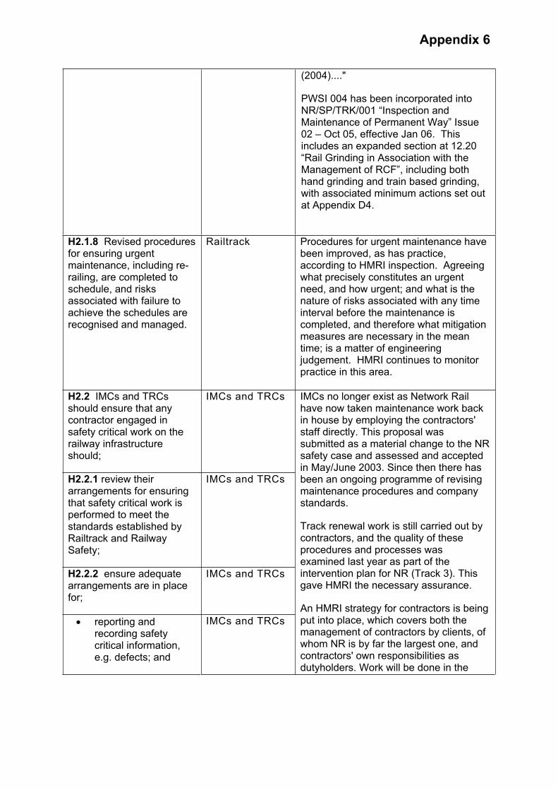
Appendix 6
(2004)...."
PWSI 004 has been incorporated into NR/SP/TRK/001 “Inspection and Maintenance of Permanent Way” Issue 02 – Oct 05, effective Jan 06. This includes an expanded section at 12.20 “Rail Grinding in Association with the Management of RCF”, including both hand grinding and train based grinding, with associated minimum actions set out at Appendix D4.
H2.1.8 Revised procedures for ensuring urgent maintenance, including re-railing, are completed to schedule, and risks associated with failure to achieve the schedules are recognised and managed.
Railtrack Procedures for urgent maintenance have been improved, as has practice, according to HMRI inspection. Agreeing what precisely constitutes an urgent need, and how urgent; and what is the nature of risks associated with any time interval before the maintenance is completed, and therefore what mitigation measures are necessary in the mean time; is a matter of engineering judgement. HMRI continues to monitor practice in this area.
H2.2 IMCs and TRCs should ensure that any contractor engaged in safety critical work on the railway infrastructure should;
IMCs and TRCs
H2.2.1 review their arrangements for ensuring that safety critical work is performed to meet the standards established by Railtrack and Railway Safety;
IMCs and TRCs
H2.2.2 ensure adequate arrangements are in place for;
IMCs and TRCs
reporting and recording safety critical information, e.g. defects; and
IMCs and TRCs
IMCs no longer exist as Network Rail have now taken maintenance work back in house by employing the contractors' staff directly. This proposal was submitted as a material change to the NR safety case and assessed and accepted in May/June 2003. Since then there has been an ongoing programme of revising maintenance procedures and company standards.
Track renewal work is still carried out by contractors, and the quality of these procedures and processes was examined last year as part of the intervention plan for NR (Track 3). This gave HMRI the necessary assurance.
An HMRI strategy for contractors is being put into place, which covers both the management of contractors by clients, of whom NR is by far the largest one, and contractors' own responsibilities as dutyholders. Work will be done in the

Appendix 6
reviewing and acting appropriately on such information (e.g. seeking possessions, imposing speed restrictions, liaising with Railtrack).
IMCs and TRCs
H2.2.3 improve systems to ensure that communications from Railtrack relating to safety critical information (e.g. alterations to standards) are acted upon and procedures are amended accordingly.
IMCs and TRCs
context of agreed strategies and priorities.
H3 Inspection of Track
H3.1 Current best practice in detecting rolling contact fatigue should be implemented. Automated (i.e. train borne) techniques should be investigated and techniques capable of detecting defects in a wider range of orientations should be developed. This work should include the evaluation of other methods for the non-destructive examination of rail (e.g. Eddy current, Alternating Current Field Measurement).
Railtrack PWSI 4 has now been incorporated into NR/SP/TRK/001 'Inspection and Maintenance of Permanent Way' Issue 02 - Issued Oct 05, for implementation Jan 06. Inspection and minimum actions for RCF are contained in Appendix D4.
HMRI 2004/5 Network Rail Inspection Assignment 1.5 'RCF on Network Rail controlled Infrastructure - PWSI4' concluded the NR Railway Safety Case adequately described relevant RCFoperations, no national issues identified.
Further HMRI Inspection and intelligence gathering work on rail mounted automated track monitoring techniques took place in 2003/4. This included the New Measurement Train, the Ultrasonic Test Unit 2 trains and the service train mounted equipment trials on Chiltern trains. No concerns expressed with rail inspection technology being employed. More work required on data management.
In February 2006 NR published two new Standard Maintenance Procedures; NR/PRC/MTC/TK0001 'Rail testing using Sperry equipped ultrasonic test unit' (Mandatory from 1 February 2006); which compliments NR/PRC/MTC/TK0084 'Management of manual ultrasonic rail testing'. Both have an effective date of 1 February 2006.
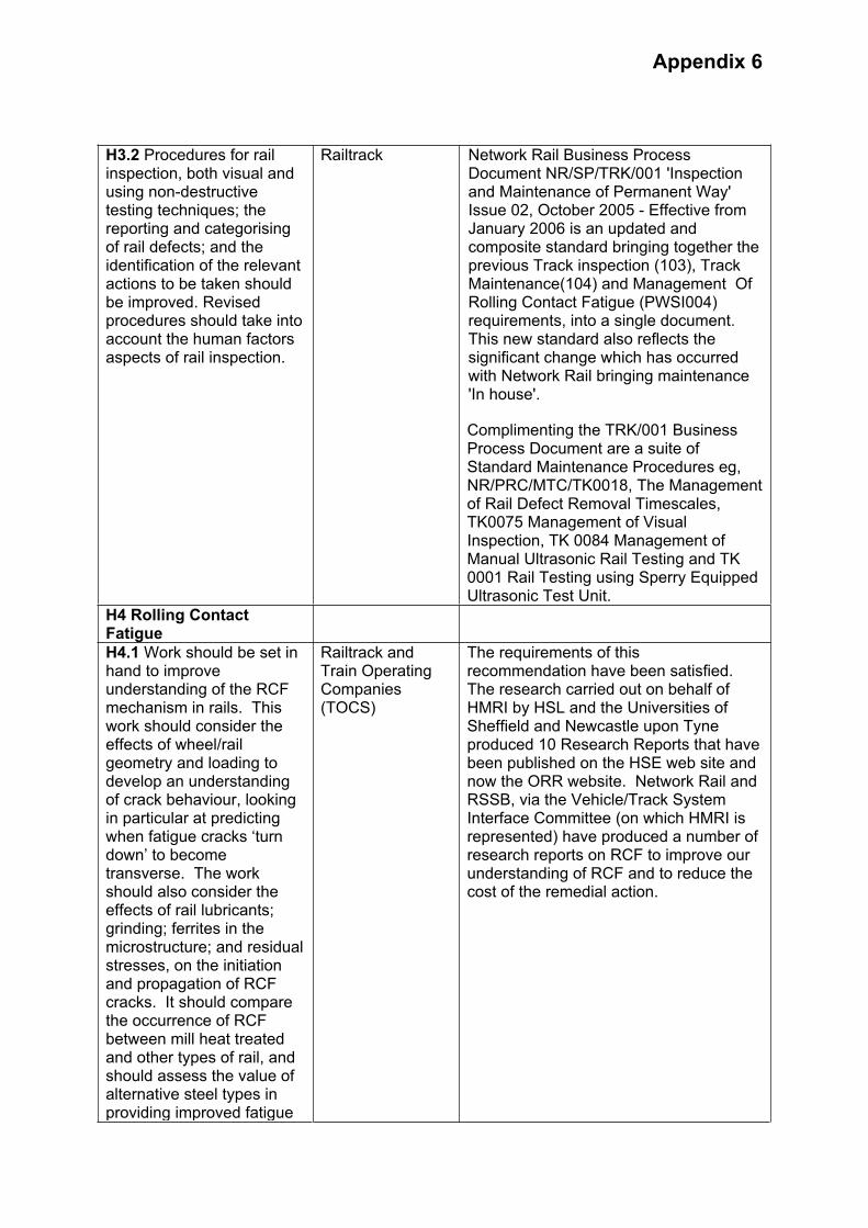
Appendix 6
H3.2 Procedures for rail inspection, both visual and using non-destructive testing techniques; the reporting and categorising of rail defects; and the identification of the relevant actions to be taken should be improved. Revised procedures should take into account the human factors aspects of rail inspection.
Railtrack Network Rail Business Process Document NR/SP/TRK/001 'Inspection and Maintenance of Permanent Way' Issue 02, October 2005 - Effective from January 2006 is an updated and composite standard bringing together the previous Track inspection (103), Track Maintenance(104) and Management Of Rolling Contact Fatigue (PWSI004) requirements, into a single document. This new standard also reflects the significant change which has occurred with Network Rail bringing maintenance 'In house'.
Complimenting the TRK/001 Business Process Document are a suite of Standard Maintenance Procedures eg, NR/PRC/MTC/TK0018, The Management of Rail Defect Removal Timescales, TK0075 Management of Visual Inspection, TK 0084 Management of Manual Ultrasonic Rail Testing and TK 0001 Rail Testing using Sperry Equipped Ultrasonic Test Unit.
H4 Rolling Contact Fatigue
H4.1 Work should be set in hand to improve understanding of the RCF mechanism in rails. This work should consider the effects of wheel/rail geometry and loading to develop an understanding of crack behaviour, looking in particular at predicting when fatigue cracks ‘turn down’ to become transverse. The work should also consider the effects of rail lubricants; grinding; ferrites in the microstructure; and residual stresses, on the initiation and propagation of RCF cracks. It should compare the occurrence of RCF between mill heat treated and other types of rail, and should assess the value of alternative steel types in providing improved fatigue
Railtrack and Train Operating Companies(TOCS)
The requirements of this recommendation have been satisfied. The research carried out on behalf of HMRI by HSL and the Universities of Sheffield and Newcastle upon Tyne produced 10 Research Reports that have been published on the HSE web site and now the ORR website. Network Rail and RSSB, via the Vehicle/Track System Interface Committee (on which HMRI is represented) have produced a number of research reports on RCF to improve our understanding of RCF and to reduce the cost of the remedial action.
Appendix 6
resistance
H5 track Design and Wheel Rail Interface
H5.1 Track and rolling stock design should be reviewed to consider the stresses on rails, the materials used, and in particular to identify whether they reduce the risk of RCF so far as is reasonably practicable. This review should take account of the likely traffic mix encountered on GB railways at typical axle loading, and the impact of tilting trains running at higher speeds.
The review process should consider the stresses on rails, and in particular the impact of cant deficiency at levels currently permitted, on high-speed curves, on RCF. It should identify any necessary improvements in the design of track fixing, bedding, or support mechanisms on these curves. The review process should take account of standards of track design, and levels of cant deficiency, approved in other countries.
Railtrack and TOCs
Many calculations on wheel/rail interface issues have been carried out for Network Rail and RSSB. The effect on the track comes from the axleload, speed and vehicle and suspension characteristics. Tilting trains have little effect except that they run round curves at a higher speed. The wheel and rail profiles have been optimised to reduce the likelihood of generating rolling contact fatigue cracks in the rails and wheels, especially from going round curves. It has been found that RCF is less likely on curves if the cant deficiency is maximised; this increases wheel flange wear. But this wear can be reduced by using flange lubricators, which is more cost effective that a lot of rail grinding to prevent RCF cracks. Interoperability will have an impact on what can be done in the UK in future. The yet to be EC approved final draft INS TSI may permit higher cant deficiencies than UK current, which will effectively satisfy this point.
Work sponsored by the Vehicle/Track SIC has shown that the vehicle primary yaw suspension stiffness is critical. A high stiffness produced RCF cracking much more rapidly than a low stiffness. As a consequence this stiffness has been reduced on some new railway vehicles.
H6 Economic Regulation
H6.1 HSE, the Office of the Rail Regulator (ORR) and the Strategic Rail Authority (SRA) should continue to review the regulatory regime to eliminate any potential conflict of priorities between meeting service delivery targets and the development of the safety culture cited in Lord Cullen’s recommendations
Railtrack and TOCs
On 15 July 2004 the Government published a White Paper “The Future of Rail” announcing major changes to address deficiences in the regulatory structure. The implementation of these changes has been completed with the abolition of the SRA and later, the merger of HMRI and ORR on 1/4/06.In addition the regulations have been modernised with the coming into force of ROGS on 10/4/06.
Lord Cullen’s recommendations on safety culture were published in 2001, comprising nos, 12 – 15 in the second report. The actions to implement these recommendations were completed by

Appendix 6
March 2004, and all the recommendations were closed.
H7 Rolling Stock and Infrastructure Design
H7.1 Train sets should be designed, built and maintained to maximise the chance of their remaining upright and intact during high-speed derailment. Particular aspects of rolling stock design which should be reviewed are
Rolling Stock Companies(ROSCOs)
Following the Hatfield derailment RSSB commissioned research into what reasonably can be done to improve vehicle crashworthiness. The first phase of the work is complete and can be found atwww.rssb.co.uk/pdf/reports/research/t118
H7.1.1 bogie and suspension component retention. Strengthening of the attachment systems should be considered;
ROSCOs HSBC has worked with consultants to develop improved bogie retention by increasing bolt size securing the centre pivot pin. Modification work for MK4 vehicles was carried out during the vehicle overhaul in 2003.
H7.1.2 ‘Tightlock’ couplers; their propensity to open when rotated should be assessed and the design loads reviewed. In addition, ‘Tightlock’ couplers from vehicles involved in accidents should not be reused unless their integrity can be assured;
ROSCOs There has been considerable development in coupler technology and associated energy absorption capabilities since the introduction of Railway Group Standard GM/RT/2100 in October 2000.
The second phase of the RSSB research (referred to above) will look in more detail at whole train dynamics including the use of and performance of couplers. This phase of the work will look at amongst other things, the recommendations issued following the Hatfield derailment.
H7.1.3 strength of vehicle roofs and walls;
ROSCOs HSBC worked with consultants to investigate the potential for improving the strength of the roof and found there was limited scope to either increase roof skin thickness or add extra carlines. Strengthening the cantrail was considered the best option and this was included in the vehicle overhaul that commenced early in 2003.
H7.1.4 passengers seats; the risks to passengers as a consequence of seat damage or failure should be reassessed; and
A major refurbishment commenced on the ICC225 coaching stock fleet from 2004 with an emphasis on enhancing vehicle interiors, including the catering vehicle to meet the requirements of

Appendix 6
H7.1.5 the design of catering facilities should be reviewed to minimise the risk to staff in the event of an accident.
ROSCOs vehicle to meet the requirements of ATOC standards AV/ST9001, Vehicle Interior Crashworthiness and AV/ST9002, Emergency Egress. All seating was renewed, replaced by a different design.
To inform future work, HSBC commissioned reports from consultants that highlighted items of the interior of the MK4 coaches that performed well or those that performed less well.
H7.2 The design of overhead line equipment stanchions should be reviewed with a view to making them less likely to penetrate passenger space in the event of a collision. In addition, the risks associated with trains striking any trackside equipment in a derailment should be assessed.
Railtrack RSSB commissioned a report shortly after Hatfield and sent it to NR for comment. The main findings centred on use of reduced factors of safety for mast holding-down bolts making them more frangible on impact as well as means of preventing loose weights at termination points from becoming detached. NR rejected the reduction in safety factors on the basis that this could lead to maintenance/reliability/performanceissues. Regarding loose weights, anti-drop device are now being fitted on all new schemes to prevent weights flying on impact. Also, the risks to trackside equipment are already assessed and depending on the consequences (usually relating to the "importance" of the equipment) measures ranging from derailment containment to relocation outside the "derailment zone" are taken. This also applies to lineside (and over-rail) structures. However this is not necessarily being done retrospecively as a "process", but on an 'as identifed' basis with new or modified works.
H8. Interim recommendations arising from data and voice tape analysis
H8.1 The provision of communications equipment for drivers should be reassessed to permit direct contact to be established between loco drivers and signalling staff (as via the cab secure radio system).
TOCs It is likely to be uneconomic to upgrade NRN, an old established technology, in order to provide direct contact between train operators and signaller staff.
Direct communication between drivers and signallers is provided in the industry's chosen future communication system, known as GSM-R. Trials for this system are expected to begin in Strathclyde before the end of 2006.

Appendix 6
A series of industry led workshops have been held where industry representatives had the opportunity to pose questions to the Network Rail led National GSM-R Programme team
In the period before GSMR comes into use HMRI will, as part of its routine interventions, assess the procedures in place to ensure that messages between train operators and signallers are relayed accurately and promptly.
RSSB produced a protocol for the use of mobile telephones whilst carrying out safety critical tasks. The protocol sets out the responsibilities for employers and employees. In addition In a bid to further improve safety critical communications on the network, representatives from across the rail industry are looking at proposals to extend the use of mobile phones by signallers and drivers.
A risk assessment workshop held at the end of May 2006 saw RSSB, Network Rail and Train Operating Companies look in detail at three areas of communication:
Drivers using a mobile phone to remind a signaller of the presence of a train at a signal Signallers using a mobile phone to give a driver authority to pass a signal at danger Drivers using mobile phones while on the move in certain circumstances
RSSB will carry out further research into the overall benefits of extending the current mobile phone protocol.
H8.2 Procedures relating to the reporting and handling of non-described alarms issued by Train Describer systems should be reviewed to identify whether these alarms provide any relevant safety information on track integrity
Railtrack Track Circuits cannot be relied upon to detect for track integrity. Therefore, train describer alarms associated with the failure to step the train describer descriptions are not in themselves a reliable means of proving track integrity.
However, Railtrack has issued procedures to ensure that signallers have clear instructions as to the action they are
Appendix 6
required to take in the event of a train description failing to step forward correctly.
H8.3 The new railway industry safety body should take responsibility for “horizon scanning” to ensure that it is aware of developments in best practice worldwide as regards the management of safety on the railways.
New Railway Industry Safety Body
Following the Cullen Inquiry into Ladbroke Grove a new railway industry safety body was established, RSSB. Under the supervision of ORR its agreed constitution included functions to “facilitate the collection and flow of information on health and safety matters in the Railway Industry”. RSSB has multifarious research projects, publications, committees and standards review groups through which it fosters and promulgates best practice.
H8.4 Education of engineers should deliver professionals who understand their professional responsibilities for the safety of the public, including the need to act on safety critical defects, and who can apply the principles of risk management
The rail industry and professional bodies
This recommendation is similar to the Action Point 34 of HSE’s “Revitalising Health and Safety”, published in June 2000. This resulted in an HSL project to incorporate risk concepts into undergraduate engineering courses and will assist in the fulfilment of this Hatfield recommendation.
The Inter-institutional Group on Health, Safety and Risk (comprising representatives of the expert groups and secretariats of the Institute of Electrical Engineers (IEE), I Mech E, Institute of Civil Engineers (ICE), Institute of Chemical Engineers (I Chem E), Hazards Forum and Ergonomics Society) has been working under Prof Richard Taylor since c. 2003 to develop stimulating and thought-provoking material for universities to use as a “toolkit” in teaching undergraduates about risk, particularly in the context of health and safety.
These documents received strong support from the Engineering Institutions, the HSE, and the Engineering Council (UK) (who saw it as a potential source for meeting accreditation requirements) as well as the Engineering Professors’ Council (EPC) and several universities.
H9. Emergency Evacuation (No recommendation)
We note that Lord Cullen, in his report of the inquiry into

Appendix 6
Ladbroke Grove train crash, made a number of recommendations on emergency arrangements, which we endorse.
H10 Safety Culture (No recommendation)
We note and fully support Lord Cullen’s recommendations as regards the need for improved health and safety culture in the railway industry

Appendix 7
EXPLANATORY NOTE OF THE SIGNALLING SYSTEM
SignalsTrain movements are controlled in accordance with the block system rules by means of signals. In the Hatfield area, the signals used are the 4-aspect colour light type to provide four different instructions. The lights are (from top to bottom) yellow green yellow and red.
Automatic Signals In the Hatfield area, on plain line, the signal is operated by the outputs from the train detection system, without the signalman being involved. It shows the least restrictive colour aspect that is permissible in the circumstances. Normally, in the absence of trains, an automatic signal shows green. At automatic signals train detection for the berth and overlap track sections is achieved using a single track circuit.
The Block System Track that does not meet or cross other lines is known as plain line. On plain line the main requirement of the signalling is that it allows one train to follow closely behind another at a safe distance. This is achieved by dividing the lines into fixed sections known as ‘blocks’. This method of operating trains is known as a ‘block system’. For safety reasons a train is not allowed to approach the entrance to an occupied block unless a short section of track beyond that entrance is clear. This short section of track is known as an overlap. A typical overlap is 183 metres long but may be shorter where train speeds are low. The section of track between the end of the overlap and the end of the block is known as a ‘berth’.
Track Circuit Block systems require some means of determining whether specified sections of track are clear or occupied. Train detection is performed completely automatically and independent of the signalman. In the Hatfield area train detection is achieved by means of track circuits. A track circuit is an electrical circuit formed from an electrical power source, the rails and current sensing equipment. The power source passes an electric current through the rails and the sensing equipment detects either a small or large current depending on whether a train is present in the section or not. A track circuit produces an output that indicates whether the specified section of track is clear or occupied.
Cross Bonding On the ECML, the signalling current arrangement is designed to provide the necessary isolation between track circuits by fitting insulated rail joints on one of each pair of rails, the signal rail. The path for the traction current to return from the train to the supply substation is via the other rail, the traction rail. In this arrangement, traction rails on pairs of adjacent tracks are connected at intervals using wire cables known as cross bonds. Cross
Appendix 7
bonding the traction return current from a train on one track to adjacent tracks reduces energy loss in the supply system and limits the voltage on the rails. Regular inspection and maintenance is necessary to ensure cross bonds are connected to the rail web.
Interlocking Equipment This equipment performs several safety-critical actions including the operation of signals over rail junctions. In the Hatfield area, these interlocking functions are performed by items of equipment known as relays housed in relay rooms. Inputs to the interlocking come from track circuits (clear or occupied), points (indicating their locked or open position), signals (indicating colour aspects displayed, lamps working etc) and the signalman requesting points to be moved, routes to be set or cancelled etc. The interlocking sends indications back to the signalbox so the signalling display can show the information that the signalman needs re the state of the railway.
Time Division Multiplexer remote control systems This is a transmission system in which information relating to a large number of independent controls and or indications from the signalman is sent over a single communication channel to the interlocking equipment.The interlocking checks all requests that are sent over the TDM remote control systems and implements only those that are safe.
Train Describer This is a computer in which the head codes of trains are stored. The head codes are set up at the beginning of the journey and the train describer displays these using small display units mounted on the signalling display.A separate display unit is provided for each track section on the approach side of a signal and each such section corresponds to a berth. The display units are referred to as berths and are identified by the signal number. So for example, the display unit associated with the berth or section of track on the approach to signal 559 would be described as berth 559. When the track circuits indicate that the train has passed the signal the train describer computer steps the head code to the next berth automatically. In normal circumstances, the signalman has no involvement in the operation of the train describer except where it is necessary to set up head codes at the beginning of a journey.
Cab Secure Radio (CSR) This is a non-signalling syst em. It is a radio system that provides 2-waycommunication between a driver and signalman. The CSR system tracks train movements using information about head codes and position obtained from the relevant train describer. The CSR system is relevant to this report because it includes a date logger that keeps records of train steps and other activities within the Kings Cross Train Describer, even for those trains that are not fitted with CSR.

Appendix 7
CCFThis used to be an acronym for ‘Contro l Centre of the Future’, a system supplied by AEATR. It provides an integrated view of current train running for use by railway controllers and other operations staff. CCF obtains real time information on train movements in the form of messages from train describers. CCF is relevant to this report because the log tape provides evidence of activities in the Kings Cross Train Describer in the period leading up to the Hatfield derailment.


Appendix 9
Assistant Track Engineer Renewals
Welding Manager South
AMEPeterboro
Technical Support Manager
Technical Support Group
IMPART Planner
Operations Manager South
Area Maintenance Engineer Kings Cross
Route Section Manager Hitchin
Assistant Route Section Manager
Track Chargemen
AME
Route Section Manger Finsbury Park
Block Item Manager
ra… Rail Flaw Detection Operatives
n ry Park
Balfour Beatty Rail Ltd M or
Balfour nce LTDM or
Regional Director Operations Manager North
Engineering Director
Chief Civil Engineer
Engineering Manager
Regional Track Engineer
Assistant Track Engineer South
Professional
Balfour Beatty PLC Managing Director
Patrolmen
Ult HitchiFinsbu
ugh
anaging Direct
Beatty Maintenaanaging Direct
Appendix 9
INDIVIDUALS RESPONSIBILITIES
Balfour Beatty +Staff from a Contractor's Saftey Case JAS 1280
and Assurance Case JAS 775
Position Description
Corporate The RT maintenance Contract requires BBRML to provide planed preventative maintenance of track, repair and replacement of assets, provision of information and maintenance records to assist RT stewardship of the assets.
Managing Director Executive responsibility for a all aspects of safety within BBRML, ensures robust processes of monitoring and auditing safety, technical standards in accordance with legislation, ensure safety monitoring and safety checks occur, ensure the Professional Heads have the powers of veto to intervence effectively on production matters, overall responsibility on Contractors Safety Case.
Engineering Director Overall responsibility for interpretation, design and audit of technical and safety standards, responsible for ensuring compliance with the Contractors Safety Case within the Engineering Department.
Civil engineer Responsible for interpretation of all civil engineering standards and developing internal standards, responsible for all civil engineering technical audits, technical support to production matters.
Regional Director Responsible for controlling safety of the infrastructure, ensuring compliance with Railway Group Standards, contract instructions (inc Railtrack Line Standards and legislation, compliance with Contractor Safety Case, safe train movements)
Regional Director Responsible for delivering the requirements of the RT1A contract, improvement of safety and performance, audits are conducted in accordance with the Company procedures, compliance with Contractors Safety Case.
Area Maintenance Engineers
Responsible for the direction of staff to achieve continuous reduction in train delays, monitoring and checking that laid down inspections are carried out and report quality is adequate, maintaining a systematic programme of audits to demonstrate compliance, ensuring all work is carried out in accordance with rules and regulations, ensuring all activities are subject to risk assessment.
Engineering Manager Maintenance of Asset Registers, interpreting changes to Railway Group Standards, legislation, advice on implementation, audits to ensure the Region retains BS EN ISO 9002 delivering Group and Line Standards and contract

Appendix 9
instruction compliance.
Track Engineer Accountable for technical activities in the Production Group comply with Railway Group & Railtrack line Standards, provide technical direction, monitoring technical performance, inform and advise when action is required to ensure compliance.
Assistant Track Engineer
No CSC responsibility. (Job Description JAS 792 summary) Provide guidance to RSMs and TSMs on track engineering, monitor track standards, monitor Ultrasonic rail defects, monitor track inspections and their quality
Route Section Managers
No CSC responsibility. (Job Description JAS 792 summary) Ensure inspections and maintenance repairs are carried out for a determined section of track.
Block item Manager No CSC responsibility. Job Description JAS 798 does not specify / reflect the work this post undertakes. Post ensures that work required within possessions for inspection / remedial work is planned e.g. URFDO work, vegetation clearance, tunnel inspections, etc.

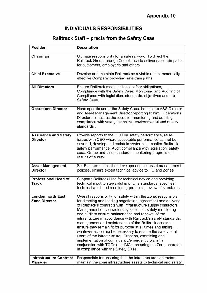
Appendix 10
INDIVIDUALS RESPONSIBILITIES
Railtrack Staff – précis from the Safety Case
Position Description
Chairman Ultimate responsibility for a safe railway. To direct the Railtrack Group through Compliance to deliver safe train paths for customers, employees and others
Chief Executive Develop and maintain Railtrack as a viable and commercially effective Company providing safe train paths
All Directors Ensure Railtrack meets its legal safety obligations, Compliance with the Safety Case, Monitoring and Auditing of Compliance with legislation, standards, objectives and the Safety Case.
Operations Director None specific under the Safety Case, he has the A&S Director and Asset Management Director reporting to him. Operations Directorate ‘acts as the focus for monitoring and auditing compliance with safety, technical, environmental and quality standards’.
Assurance and Safety Director
Provide reports to the CEO on safety performance, raise issues with CEO where acceptable performance cannot be ensured, develop and maintain systems to monitor Railtrack safety performance, Audit compliance with legislation, safety case, Group and Line standards, monitoring progress on results of audits.
Asset Management Director
Set Railtrack’s technical development, set asset management policies, ensure expert technical advice to HQ and Zones.
Professional Head of Track
Supports Railtrack Line for technical advice and providing technical input to stewardship of Line standards, specifies technical audit and monitoring protocols, review of standards.
London north East Zone Director
Overall responsibility for safety within the Zone; responsible for directing and leading negotiation, agreement and delivery of Railtrack’s contracts with Infrastructure supply contactors. Management of contractors by selection, safety monitoring and audit to ensure maintenance and renewal of the infrastructure in accordance with Railtrack’s safety standards, management and maintenance of the Railtrack assets to ensure they remain fit for purpose at all times and taking whatever action ma be necessary to ensure the safety of all users of the infrastructure. Creation, exercising and implementation of contingency/emergency plans in conjunction with TOCs and IMCs, ensuring the Zone operates in compliance with the Safety Case.
Infrastructure Contract Manager
Responsible for ensuring that the infrastructure contractors maintain the zone infrastructure assets to technical and safety
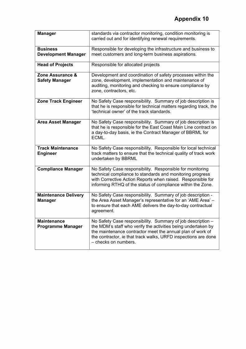
Appendix 10
Manager standards via contractor monitoring, condition monitoring is carried out and for identifying renewal requirements.
BusinessDevelopment Manager
Responsible for developing the infrastructure and business to meet customers and long-term business aspirations.
Head of Projects Responsible for allocated projects
Zone Assurance & Safety Manager
Development and coordination of safety processes within the zone, development, implementation and maintenance of auditing, monitoring and checking to ensure compliance by zone, contractors, etc.
Zone Track Engineer No Safety Case responsibility. Summary of job description is that he is responsible for technical matters regarding track, the ‘technical owner’ of the track standards.
Area Asset Manager No Safety Case responsibility. Summary of job description is that he is responsible for the East Coast Main Line contract on a day-to-day basis, ie the Contract Manager of BBRML for ECML.
Track Maintenance Engineer
No Safety Case responsibility. Responsible for local technical track matters to ensure that the technical quality of track work undertaken by BBRML
Compliance Manager No Safety Case responsibility. Responsible for monitoring technical compliance to standards and monitoring progress with Corrective Action Reports when raised. Responsible for informing RTHQ of the status of compliance within the Zone.
Maintenance Delivery Manager
No Safety Case responsibility. Summary of job description - the Area Asset Manager’s representative for an ‘AME Area’ – to ensure that each AME delivers the day-to-day contractual agreement.
MaintenanceProgramme Manager
No Safety Case responsibility. Summary of job description – the MDM’s staff who verify the activities being undertaken by the maintenance contractor meet the annual plan of work of the contractor, ie that track walks, URFD inspections are done – checks on numbers.
One Kemble Street
London
WC2B 4AN
T: 020 7282 2000
F: 020 7282 2040
www.rail-reg.gov.uk


![HSL-3 EXPANSION ANCHOR · 2020. 10. 15. · Updated: Oct-20 4 HSL-3-SH / HSL-3-SKa) Shear V Rec HSL-3 / HSL-3-B [kN] 14,3 17,8 17,8 20,1 29,3 34,6 24,5 36,9 50,8 HSL-3-G 14,3 14,9](https://img.dokumen.tips/doc/110x75/61188027c3aeb93d607a5cb7/hsl-3-expansion-anchor-2020-10-15-updated-oct-20-4-hsl-3-sh-hsl-3-ska-shear.jpg)