Embed Size (px)
Citation preview

ORGANIZING AND PLANNING FOR PRODUCTION
PART I
Loren D. Butler
Dolphyn Engineering Company
bur profession is best served in that di- lemma called “What next’?” Such was the case within a customer’s plant. This client, a large midwestern corporation, is engaged in the pro- duction of ICBM and surface missile systems as well as electronic naviational systems. The problems referred to above were in the field of electromechanical production. They had grown and multiplied in such a way that they created a serious bottleneck infinal assembly, and immedi- ate solutions were called for by top management.
Currently, this problem area is being given widespread publicity as it comes under the light of value analysis in plants over the nation which are engaged in electronics production. Spe cifi - tally, the’problem area is the production of electrical wiring harnesses in sufficient quantity while maintinaing high quality, and also, the pro- duction of completedelectronic assemblies con- sisting of chassis or console with wiring harnesses and components installed Of greater import- ance and running consequent to the production bottleneck in this plant was the prohibitive cost of units produced. Primarily, our task was to reduce these costs which had brought about the cost-cutting program now under way.
The startling proportions of this problem were clearly indicated by statements published by the U.S. Government and presented at the 1960 Ballistic Missile Seminar held in Hunsville, Ala. “The Production of Electronic Assemblies with wiring harnesses comprises more than 30% of the assembly cost of Missiles.” Of course, in this context the statement highlights the seri- ousness of this problem throughout the missile industry as a whole as well as in our customer’s plant. Further, this publication and our cus- tomer’s action indicate a recognition of the prob- lem jointly by government agencies and private industry so that industry-wide action is forth- coming. It is sincerely hoped that the writing of this paper will make a substantial contribu- tion toward that action.
The electromechanical assemblies referred to in this paper consist, as the name implies, of all types of electrical-power-operated and cnntrol systems, although they are not limited entirely to this field. Frequently, pneumatic and hydraulic units such as servo units, valves, and pressure regulators are involved. These assemblies are functionally either a part of ground checkout equipment; launch control sys- tem, an integral part of the missile; or frequent- ly a part of ground support installation, either stationary or portable. No reservations shall
be made here as to the variety of electrical or electronic components involved, since every type of unit is utilized, including television, ra- dio, and radar.
The electrical wiring harnesses were the signal wires, grounding system, and power de- livery system which interconnected the above components. They range in size to over 3000 wires within a single harness having a variety of coverings such as teflon, polyvinyl, mesh. shielding, and special purpose insulation cover- ings, end fittings for the individual wire leads range from terminal lugs to crimp-type con- nector pins. The bulk of wire leads were in size No. 16 and No. 20 but ranging from size No. 24 to No. 4 wire. The completely laid harness bound and tied at specified intervals with lacing cord was of thickness varying up to 3 l/2 in.
Wiring harnesses of the industry fall into two general classifications:
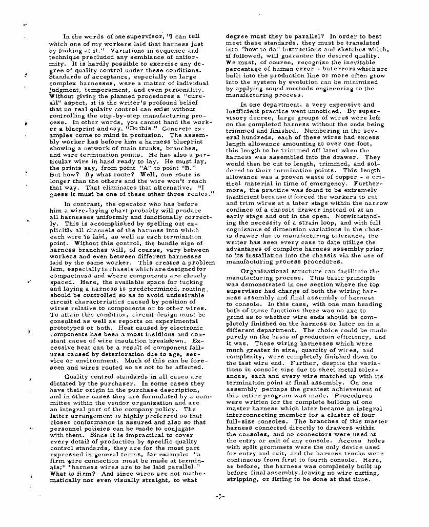
1) Chassis harnesses which interconnect electronic components within a slide- in/out-type drawer. These drawers are: top view, 24 x 24 in and 17 in deep, and built for the purpose of. mounting into consoles (see Fig. 1).
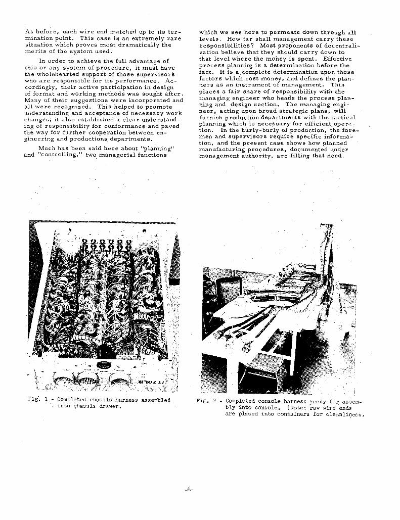
2) Console harnesses which interconnect drawers or which interconnect consoles such as ground checkout consoles and launch control readout consoles. These consoles are generally of standard con- figuration being: top view, 24 x 24 in and 6 ft high, with instruments and con- trol knobs on the front side for operat- ing personnel (see Fig. 2).
Basically, the electrical wiring harness does not lend itself to labor-saving automation techniques commonly used by the metal-cutting trades. This is due to the nature of wire, since it will not maintain shape once formed, and tends to spring out of shape or position unless retained at such close intervals as to be impractical. Moreover, the engineer is closely restricted in his alternatives by consideration of side-effects such as the inducement of undesirable circuit characteristics where wires are routed adjacent to HF carriers or the cutting effects of sharp edges caused by vibration, burning of insulation due to heat of components, and the effect of shock upon components. Many efforts had been made and in a few instances, successfully, to apply continuous process methods rather than job-lot.
-3-

The most successful over-all plan was a com- promise between the two systems with produc- tion methods which streamlined the intervals between job lots. It was necessary to develop manufacturing process procedures which would accomplish this.
The many factors which brought about this move had far-reaching effects throughout the organization, impinging upon union-management relations and the organizational structure itself. During the ,research and design stage, skilled technicians in great numbers had been required . to lay out the harness wires, assemble the end fittings, bind up the harness branches and assem- ble the finished harness into the drawer or con- sole, These technicians were required during this early stage because of their specialized skill at doing this work with only preliminary schemat- ic design information to work by. However, after the research and design phase was com- plete, finished design prints were available, and the program moved into the production phase. Production costs were based upon the use of un- skilled labor for this work, and accordingly, technicians were now transferred to new posi- tions which demanded their skill and they were replaced by unskilled labor. Union feelings ran high in the wake of this move because of the wage differential between unskilled labor and highly- skilled technicians. Also, production bogged down due to lack of training aids.
At this point it was decided to place in the workers’ hands an engineered, planned-out-in- detail, illustrated and descriptive process pro- cedure for each job. It was considered that, if the engineering information contained on blue- prints and technical specifications was trans- lated into everyday language and picures, then not only would the unskilled workers’ need for understandable information be satisfied, but also the learning curve for new employees and transfers wouldbe much sharper. The problem of interpreting engineering design into understanda- ble information and communicating this informa- tion to the workers was solved. The training problem began to look less monstrous with the use of adequate tools, and, once trained, a greater number of workers could be supervised directly by each supervisor because each worker, having been supplied with a detailed picure for each step in his job, would require less supervision.
Repeated time-studies showed that, for small harness assemblies (under 200 wires), the time-savings with written procedures equalled their cost at the point of three or four units re- quired - this as against the break-in cost of a worker on the same job, without written pro- cedures. On large jobs, the time-savings were on the positve side with only one unit required. This is due in part to the simplified nature of the written procedure as against the mass of in- formation contained in the prints and technical orders. The simplified point-to-point wire lay- ing chart illustrated in Figs. 3-5 bears out this point quite obviously when laid side by side with
a wiring harness blueprint such as had been previously furnished these workers to do the same job. Also, the savings is due to the re- duction of cases where wires must be torn out of the harness and rerouted after the assembly has been completed and a buzzout test indicates a mislaid wire.
Financial apportionments for the assembly departments along the line were supposedly based upon their proportionate share of materi- al and labor contributed to the funished product. However, due to the lack of documented proce- dures, management had no concise records upon which to base its control procedures. As a con- sequence, production supervisors were left to decide which departments would perform the various operations, and those departmental su- pervisors of stronger personality succeeded in building empires based solely upon this week- ness in managerial control. Continual bicker - ing and dickering resulted, and nobody could prove anything in the event of an accounting. Some departments were affected very favorably by this confusion, and others very badly. Some were operating in deficit and others with surplus as a result of the shifting of costs outside of the proper financial control.
This condition was quite prevalent for instance, between wiring harness assembly and chassis drawer assembly. Without informing the engineering department and with no authori- ty beyond their own, the supervisors of these two departments decide to omit a group of com- ponents (in one instance, 63) from the chassis drawer and assemble them to the harness in the harness department prior to its assembly into the chassis drawer. This is a good idea from a manufacturing standpoint, but sound proce- dure in this instance would dictate that an ap- proved revision be recorded in the written pro- cedures and that this revision be circulated to all cognizant parties. As precaution, revisions such as this should be handled in such a way as not to affect interchangeability of spare parts.
The manufacturing process procedure provided management with the missing link in cost control procedure. Qualified personnel could now tally the production cost at any stage of progress, since the process sheets contain listed the materials required, parts, tools, machines , man -hours , and the department to which each operation was assigned. From this coordinated working sheet, budget cost centers emerged as a clear focal point, and a basis for communication was established between mana- gers and shop foremen. It can readily be seen here that these documents served not only as a practical function in the shop, but also served, in the hands of management, to strengthen the lines of responsibility and the organizational structure as a whole. Digressing for one mo- ment, much more will be said later about the format used. The application of good form de- sign here can eliminate much costly duplication plant -wise, and properly channel this highly con- centrated information to responsible people.
In the words of one supervisor’; “I can tell which one of my workers laid that harness just by looking at it.” Variations in sequence and technique precluded any semblance of unifor- mity. It is hardly possible to exercise any de-
3 gree of quality control under these conditions. Standards of acceptance, especially on large complex harnesses, were a matter of individual judgment, temperament, and even personality. Without giving the planned procedures a “cure- all” aspect, it is the writer’s profound belief that no real qulaity control can exist without controlling the stip-by-step manufacturing pro- cess. In other words, you cannot hand the work- er a blueprint andsay, “Dothis.” Concrete ex- amples come to mind in profusion. The assem- bly worker has before him a harness blueprint showing a network of main trunks, branches, and wire termination points. He has also a par- ticular wire in hand ready to lay. He must lay, the prints say, from point “A” to point ‘IB.” But how? By what route? Well, one route is
! longer than the others and the wire won’t reach that way. That eliminates that alternative. “I guess it must be one of these other three routes.”
In contrast, the operator who has before him a wire-laying chart probably will produce
* all harnesses uniformly and functionally correct- 1Y. This is accomplished by spelling out ex- plicitly all channels of the harness into which each wire is laid, as well as each termination point. Without this control, the bundle size of harness branches will, of course, vary between workers and even between different harnesses laid by the same worker. This creates a problem lem, especially in chassis which are designed for compactness and where components are closely
I’ spaced. Here, the available space for tucking and laying a harness is predetermined, routing, should be controlled so as to avoid undesirable circuit characteristics caused by position of wires relative to components or to other wires. To attain this condition, circuit design must be consulted as well as reports on experimental
i prototypes or both. Heat caused by electronic components has been a most insidious and con- stant cause of wire insulation breakdown. Ex- cessive heat can be a result of component fail- ures caused by deterioration due to age, ser- vice or environment. Much of this can be fore- seen and wires routed so as not to be affected.
Quality control standards in all cases are dictated by the purchaser. In some cases they have their origin in the purchase description, and in other cases they are formulated by a com- mittee within the vendor organization and are an integral part of the company policy. The latter arrangement is highly preferred so that closer conformance is assured and also so that personnel poliaies can be made to conjugate with them. Since it is impractical to cover every detail of production by specific quality control standards, they are for the most part expressed in general terms, for example: “a firm Wire connection must be made at termin- als;” “harness wires are to be laid parallel.” What is firm? And since wires are not mathe- matically nor even visually straight, to what
degree must they be parallel? In order to best meet these standards, they must be translated into “how to do” instructions and sketches which, if followed, will guarantee the desired quality. We must, of course, recognize the inevitable percentage of human error - but errors which are built into the production line or more often grow into the system by evolution can be minimized by applying sound methods engineering to the manufacturing process.
In one department, a very expensive and inefficient practice went unnoticed. By super- visory decree, large groups of wires were left on the completed harness without the ends being trimmed and finished. Numbering in the sev- eral hundreds, each of these wires had excess length allowance amounting to over one foot, this length to be trimmed off later when the harness was assembled into the drawer. They would then be cut to length, trimmed, and sol- dered to their termination points. This length allowance was a proven waste of copper - a cri- tical material in time of emergency. Further- more, the practice was found to be extremely inefficient because it forced the workers to cut and trim wires at a later stage within the narrow confines of a chassis drawer instead of at an early stage and out in the open. Notwithstand- ing the necessity of a strain loop, and with full cognizance of dimension variations in the chas- is drawer due to manufacturing tolerance, the writer has seen every case to date utilize the advantages of complete harness assembly prior to its installation into the chassis via the use of manufacturing process procedures.
Organizational structure can facilitate the manufacturing process. This basic principle was demonstrated in one section where the top supervisor had charge of both the wiring har- ness assembly and final assembly of harness to console. In this case, with one man heading both of these functions there was no axe to grind as to whether wire ends should be com- pletely finished on the harness or later on in a different department. The choice could be made purely on the basis of production efficiency, and it was. These wiring harnesses which were much greater in size, quantity of wires, and complexity, were completely finished down to the last wire end. Further, despite the varia- tions in console size due to sheet metal toler- ances, each and every wire matched up with its termination point at final assembly. On one assembly perhaps the greatest achievement of this entire program was made. Procedures were written for the complete buildup of one master harness which later became an integral interconnecting member for a cluster of four full-size consoles. The branches of this master harness connected directly to drawers within the consoles, and no connectors were used at the entry or exit of any console. Access holes with split grommets were the only device used for entry and exit, and the harness trunks were continuous from first to fourth console. Here, as before, the harness was completely built up before final assembly, leaving no wire cutting, stripping, or fitting to be done at that time.
-5-
As before, each wire end matched up to its ter- mination point. This case is an extremely rare situation which proves most dramatically the merits of the system used.
In order to achieve the full advantage of this or any system of procedure, it must have the wholehearted support of those supervisors who are responsible for its performance. Ac- cordingly, their active participation in design of format and working methods was sought after. Many of their suggestions were incorporated and all were recognized. This helped to promote understanding and acceptance of necessary work changes; 1 ‘t also established a clear understand- ing of responsibility for conformance and paved the way for’ further cooperation between en- gineering and productions departments.
Much has been said here about “planning” and “controlling,” two managerial functions
Fig’. 1 - Completed chassis harness assembled into chassis drawer..
which we see here to permeate down through all levels. How far shall.management carry these responsibilities? Most proponents of decentrali- zation believe that they should carry down to that level where the money is spent. Effective process planning is a determination before the fact. It is a complete determination upon those factors which cost money, and defines the plan- ners as an instrument of management. This places a fair share of responsibility with the managing engineer who heads the process plan- ning and design section. The managing’engi- neer, acting upon broad strategic plans, will furnish production departments with the tactical planning which is necessary for efficient. opera: tion. In the hurly-burly of production, the fore- men and supervisors require specific informal tion, and the present case shows how planned manufacturing procedures, documented under management authority, are filling that need.
Fig. 2 - Completed console harness ready for assem- bly into console. (Note: ‘raw wire ‘ends are placed into containers +or cleanliness
-6-
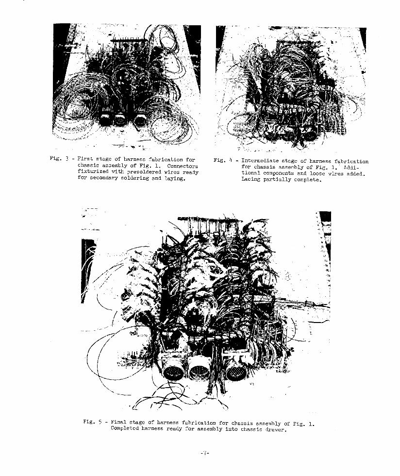
Fig. 3 - First stage of harness fabrication for chassis assembly of Fig. 1. Connectors fixturized with presoldered wires ready for secondary soldering and laying.
Fig. 4 - Intermediate stage of harness fabrication for chassis assembly of Fig. 1.' Addi- tional components and loose wires added. Lacing partially complete.
Fig. 5 - Final stage of harness fabrication for chassis assembly of Fig. 1. Completed harness ready for assembly into chassis drawer.
-7-