Embed Size (px)
Citation preview

Orbiter Electrical Orbiter Electrical Power SystemPower System

Orbiter Electrical Power System (EPS)Orbiter Electrical Power System (EPS)
The electrical power system for the Orbiter was The electrical power system for the Orbiter was designed with three important goals in mind designed with three important goals in mind
1. Reliability1. Reliability
2. Simplicity2. Simplicity
3. Proven technology3. Proven technology

Orbiter EPSOrbiter EPS
Fuel cells for manned spacecraft were developed for aerospace applications and first used in the Gemini program Space applications were developed specifically
for the Apollo missions because of their byproduct – water
Electrical power design for the new Orbiter included the utility of fuel cells to provide water from the H2 and O2 reactants, and for the O2 reactant to also serve as the O2 supply for the crew

Orbiter EPSOrbiter EPS
Weight savings from not having to launch the water needed for the entire mission was a greater advantage than the disadvantages of the added weight, volume, and complexity of the cryogenic reactant storage
To improve the electrical power system (EPS) efficiency and reliability, the Orbiter’s fuel cell system was designed to power the entire STS (Orbiter + ET + SRBs)

Orbiter EPSOrbiter EPS
The Orbiter's electrical power supply is a triple-The Orbiter's electrical power supply is a triple-redundant systemredundant system Three independent fuel cells supply three individual power Three independent fuel cells supply three individual power
buses for all of the STS system loadsbuses for all of the STS system loads
The three fuel cells can be interconnected, and The three fuel cells can be interconnected, and generally are generally are Provide continuous triple redundancyProvide continuous triple redundancy System includes automated load managementSystem includes automated load management
Isolation of circuits is also a part of the basic designIsolation of circuits is also a part of the basic design Reduces the potential for catastrophic failure in one of the Reduces the potential for catastrophic failure in one of the
onboard systems or fuel cells damaging or destroying the onboard systems or fuel cells damaging or destroying the rest of the electrical power systemrest of the electrical power system

EPS – External PowerEPS – External Power
Electrical power is furnished in Electrical power is furnished in preflight, post-landing, and during preflight, post-landing, and during processing by external sources called processing by external sources called Ground Service Equipment (GSE)Ground Service Equipment (GSE)
GSE power is mobile in some cases, GSE power is mobile in some cases, and fixed while in the processing, and fixed while in the processing, assembly, and launch preparation assembly, and launch preparation phasesphases
Electrical power from the GSE is fed Electrical power from the GSE is fed through the umbilical panel called the through the umbilical panel called the T-0 panel T-0 panel T-0 panel is located on the aft right T-0 panel is located on the aft right
and left sections of the Orbiter that and left sections of the Orbiter that allows power, fluid, gas, and signal allows power, fluid, gas, and signal connectionsconnections

EPSEPS
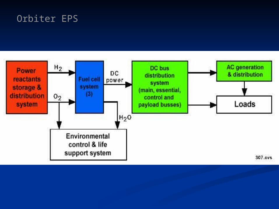
The Orbiter's Electrical Power System The Orbiter's Electrical Power System consists of three main subsystemsconsists of three main subsystems
Fuel cell power generators (FCs)Fuel cell power generators (FCs)
Electrical Power Distribution and Control Electrical Power Distribution and Control (EPDC)(EPDC)
Power Reactant Storage and Distribution Power Reactant Storage and Distribution System (PRSD)System (PRSD)
Orbiter EPS

EPS – Fuel CellsEPS – Fuel Cells
Fuel cell advantages over conventional Fuel cell advantages over conventional spacecraft powerspacecraft power
Water byproduct Water byproduct
Efficient conversion of reactant mass into electrical Efficient conversion of reactant mass into electrical energy energy
High power output (7-10 kW per power unit) High power output (7-10 kW per power unit)
Power output is dependent only on load Power output is dependent only on load requirements (small standby power necessary) requirements (small standby power necessary)

EPS – Fuel CellsEPS – Fuel Cells
Fuel cell advantages over conventional Fuel cell advantages over conventional spacecraft powerspacecraft power
Modular components could be replaced as necessary Modular components could be replaced as necessary (during processing, not on orbit)(during processing, not on orbit)
Vibration and noise free operation Vibration and noise free operation
Low maintenance required during mission operations Low maintenance required during mission operations
Relatively low weight Relatively low weight
Liquid oxygen was also required for crew life supportLiquid oxygen was also required for crew life support

EPS – Fuel CellsEPS – Fuel Cells
Fuel cell disadvantagesFuel cell disadvantages
Cryogenic reactant storage and distribution were complex, Cryogenic reactant storage and distribution were complex, costly, and hazardous in manned spacecraft costly, and hazardous in manned spacecraft
Technology for the reliable operation of fuel cells was not Technology for the reliable operation of fuel cells was not considered mature since it had only been used on the Apollo considered mature since it had only been used on the Apollo missions, and then with some difficulty missions, and then with some difficulty
High maintenance and relatively high operational cost High maintenance and relatively high operational cost
Water byproduct contains hydrogen gas (minor complication Water byproduct contains hydrogen gas (minor complication since it can be removed)since it can be removed)

EPS – Fuel Cells (FC)EPS – Fuel Cells (FC)
Each fuel cell consists of:Each fuel cell consists of:
Power section that generates the electrical powerPower section that generates the electrical power
Accessory section which regulates the fuel cell operationsAccessory section which regulates the fuel cell operations
Each fuel cell is:Each fuel cell is:
Reusable and restartableReusable and restartable
Operated independently to power the three main 28-volt dc Operated independently to power the three main 28-volt dc electrical buses at a nominal output of 7 kWelectrical buses at a nominal output of 7 kW

EPS – Fuel Cells (FC)EPS – Fuel Cells (FC)
Since the FC power output depends on the electrical Since the FC power output depends on the electrical load, the power output can range from load, the power output can range from approximately 2 kW (standby) to a maximum of 12 approximately 2 kW (standby) to a maximum of 12 kW (nominal = 7 kW)kW (nominal = 7 kW)
Varying load values change the fuel cell power Varying load values change the fuel cell power output, which corresponds to a change in the output, which corresponds to a change in the current output since the voltage is fixed at 28 Vdccurrent output since the voltage is fixed at 28 Vdc
Any change in the load on the respective bus will Any change in the load on the respective bus will change the fuel cell current output in proportionchange the fuel cell current output in proportion

EPS – Fuel CellsEPS – Fuel Cells
Each fuel cell is connected to an independent, isolated DC bus All three buses have
cross-ties Crossover circuits are
also provided for a number of the subdivided buses
Alternating current is generated on three independent AC buses that are connected to the three main DC bus lines

EPS – Fuel CellsEPS – Fuel Cells
The three fuel cells (A, B, C) and their main The three fuel cells (A, B, C) and their main buses (A, B, C) supply the Orbiter and STS buses (A, B, C) supply the Orbiter and STS vehicle with all of its electrical power and for its vehicle with all of its electrical power and for its entire missionentire mission
Battery power is found in several small battery Battery power is found in several small battery supplies for pyrotechnic device activationsupplies for pyrotechnic device activation

EPS – Fuel Cell Power SectionEPS – Fuel Cell Power Section
The FC power section consists of 96 cellsThe FC power section consists of 96 cells Each cell generates a fraction of the total current Each cell generates a fraction of the total current
by the diffusion of hydrogen and oxygen across a by the diffusion of hydrogen and oxygen across a conductive electrolyteconductive electrolyte
Liquid oxygen and liquid hydrogen are heated to Liquid oxygen and liquid hydrogen are heated to supply the pressurized reactant gases that flow supply the pressurized reactant gases that flow through each end of the cell, while Freon flows through each end of the cell, while Freon flows around the cell to remove the heataround the cell to remove the heat
Gas and coolant pressures are carefully regulated to Gas and coolant pressures are carefully regulated to avoid excessive flow, reverse flow, or cell warpingavoid excessive flow, reverse flow, or cell warping

EPS – Fuel Cell Power StackEPS – Fuel Cell Power Stack
Chemical reaction and power production section
Contains an assembly of 3 substacks
Comprised of 96 individual cells (32 per substack) bolted together between end plates
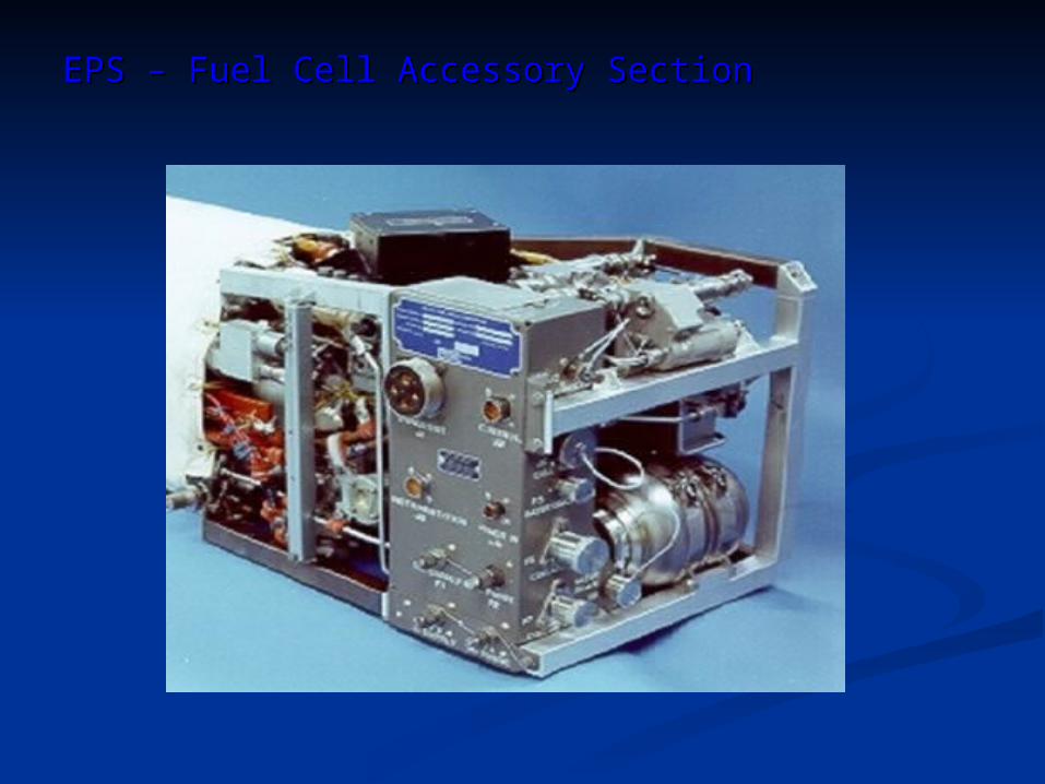
EPS – Fuel Cell Accessory SectionEPS – Fuel Cell Accessory Section

EPS – Fuel Cell Accessory SectionEPS – Fuel Cell Accessory Section
Accessory section functional subsections include:Accessory section functional subsections include:
Reactant supply to cells as gasReactant supply to cells as gas
Water removalWater removal
Purge system (debris removal) Purge system (debris removal)
Coolant loop and temperature controlCoolant loop and temperature control
Cell performance monitor Cell performance monitor
Electrical power output control unitElectrical power output control unit

EPS – Fuel Cell Accessory Section Functions (cont.)EPS – Fuel Cell Accessory Section Functions (cont.)
Preheater to produce HPreheater to produce H22 & O & O22 gas from cryogenic gas from cryogenic liquidliquid
Gas supply temp approximately 40Gas supply temp approximately 40ooF F
Distribute reactants to subcell electrodes Distribute reactants to subcell electrodes OO22 gas at 62-65 psia gas at 62-65 psia HH22 gas 4.5-6 psia below O gas 4.5-6 psia below O22 pressure pressure
Monitor reactant flow Monitor reactant flow
Monitor power performance Monitor power performance
Heat exchanger to outer Active Thermal Control Heat exchanger to outer Active Thermal Control System (ATCS) loopSystem (ATCS) loop

EPS – Fuel Cell CellsEPS – Fuel Cell Cells
Individual cellsIndividual cells
Each of the FC's 96 cells contribute to the Each of the FC's 96 cells contribute to the power generation processpower generation process
Individual cells facilitate ion flow through an Individual cells facilitate ion flow through an electrolyteelectrolyte Allows a controlled reaction of hydrogen and Allows a controlled reaction of hydrogen and
oxygen indirectly (the same reactants are also oxygen indirectly (the same reactants are also propellants)propellants)

EPS – Fuel Cell CellsEPS – Fuel Cell Cells
Individual cellsIndividual cells
Combining the OCombining the O22 and H and H22 reactants indirectly reactants indirectly
produces excess electrons, water and heatproduces excess electrons, water and heat
Extraction of both heat and water from the cell is a Extraction of both heat and water from the cell is a major element of the fuel cell's designmajor element of the fuel cell's design Both have a direct on the fuel cell stack efficiencyBoth have a direct on the fuel cell stack efficiency
Physical separation of the OPhysical separation of the O22 and H and H22 reactants is reactants is
maintained by the interchange of ions through the maintained by the interchange of ions through the saturated KOH (potassium hydroxide) electrolytesaturated KOH (potassium hydroxide) electrolyte

EPS – Fuel Cell StackEPS – Fuel Cell Stack
Diffusion of hydrogen and oxygen gas in the cell occurs from opposite sides of the cell frame

EPS – Fuel Cell CellsEPS – Fuel Cell Cells
•Cell structure circulates the reactants and the Freon coolant through separate distribution channels called manifolds
•Hydrogen manifold at the top is also the circulation manifold for the water/steam
•Hydrogen is combined with the hydroxyl ion (OH) that is passed from the oxygen side to form H2O

EPS – Fuel Cell Assembled StackEPS – Fuel Cell Assembled Stack

EPS – Fuel Cell OperationsEPS – Fuel Cell Operations
Fuel Cell Performance

EPS – Fuel Cell PerformanceEPS – Fuel Cell Performance
Output of the Orbiter's fuel cells is dependent on a Output of the Orbiter's fuel cells is dependent on a number of variables that include but are not limited number of variables that include but are not limited to:to: External power loadExternal power load Water and electrolyte concentrationWater and electrolyte concentration Cell temperatureCell temperature Reactant temperatureReactant temperature Contaminant buildup within the cellContaminant buildup within the cell

EPS – Fuel Cell PerformanceEPS – Fuel Cell Performance
Fuel cell power production and the reactant Fuel cell power production and the reactant consumption is directly proportional to the electrical consumption is directly proportional to the electrical power loadpower load Unlike a photovoltaic array, if no load is Unlike a photovoltaic array, if no load is
connected to the fuel cell, no reactants are connected to the fuel cell, no reactants are consumed and no power is generatedconsumed and no power is generated
A zero load on a fuel cell can be a problem for its A zero load on a fuel cell can be a problem for its continual operationcontinual operation A cross-tie circuit is designed into the EPS to A cross-tie circuit is designed into the EPS to
maintain a minimum load of approximately 2 kW maintain a minimum load of approximately 2 kW on each fuel cell to prevent system degradationon each fuel cell to prevent system degradation

EPS – Fuel Cell PerformanceEPS – Fuel Cell Performance
Orbiter fuel cell outputOrbiter fuel cell output
PowerPower Voltage Voltage DurationDuration # FCs# FCs
2 kW 2 kW 32.5 Vdc 32.5 Vdc ContinuousContinuous EachEach
12 kW12 kW 27.5 Vdc27.5 Vdc ContinuousContinuous EachEach
7 kW7 kW 28 Vdc28 Vdc ContinuousContinuous EachEach
10 kW10 kW 28 Vdc28 Vdc Peak - 1 hourPeak - 1 hour EachEach12 kW12 kW 28 Vdc28 Vdc Peak - 15 minPeak - 15 min EachEach
16 kW16 kW 28 Vdc28 Vdc Peak - 10 minPeak - 10 min EachEach21 kW21 kW 28 Vdc28 Vdc ContinuousContinuous 33
36 kW36 kW 28 Vdc28 Vdc Peak - 15 minPeak - 15 min 33

EPS – Fuel Cell PerformanceEPS – Fuel Cell Performance
FC output power plot FC output power plot (current x voltage = power)(current x voltage = power)

EPS – Fuel Cell StatsEPS – Fuel Cell Stats
Voltage regulationVoltage regulation 27.5 - 32.5 Vdc27.5 - 32.5 Vdc
WeightWeight 262 lb262 lb
DimensionsDimensions 14" high x 15" wide x 40" 14" high x 15" wide x 40" longlong
Max heat rejectionMax heat rejection 4,800 Btu/hr (2 kW) 4,800 Btu/hr (2 kW) to 25,000 Btu/hr (12 to 25,000 Btu/hr (12
kW)kW)Max water production rateMax water production rate 1.8 lb/hr (2 kW) 1.8 lb/hr (2 kW)
to 10.7 lb/hr (12 kW)to 10.7 lb/hr (12 kW)
Maximum time to full outputMaximum time to full output 25 min25 min
Maximum time for shutdownMaximum time for shutdown 1 min1 min
Start/stop cycles for 2,000 hr lifeStart/stop cycles for 2,000 hr life 5050
Start/stop cycles for 5,000 hr lifeStart/stop cycles for 5,000 hr life 125125

EPS – Fuel Cell OperationsEPS – Fuel Cell Operations
Fuel Cell Operation

EPS – Fuel Cell OperationEPS – Fuel Cell Operation
Reactant flow within the cell and separator plates Reactant flow within the cell and separator plates provides for a large surface area for ion exchange provides for a large surface area for ion exchange between the Hbetween the H22 and O and O22 products products Electron (eElectron (e--) and hydroxyl (OH) and hydroxyl (OH--) ions ) ions
Potassium hydroxide electrolyte and water Potassium hydroxide electrolyte and water saturate a porous material that allows sufficient saturate a porous material that allows sufficient conductivity for ion flow to generate the electrical conductivity for ion flow to generate the electrical power through an external conductive loop (the power through an external conductive loop (the load)load)

EPS – Fuel Cell OperationEPS – Fuel Cell Operation
With the voltage fixed, or nearly so, the power With the voltage fixed, or nearly so, the power produced is equivalent to the rate of ion flow produced is equivalent to the rate of ion flow (current)(current)
Buildup of the water byproduct in the cell decreases Buildup of the water byproduct in the cell decreases ion flow and therefore degrades power outpution flow and therefore degrades power output Water extraction is an important and continually Water extraction is an important and continually
active process in the fuel cell control subsystem active process in the fuel cell control subsystem to maintain efficient power productionto maintain efficient power production
EPS – Fuel Cell OperationEPS – Fuel Cell Operation
Fuel cell operation is contingent on the purity of the Fuel cell operation is contingent on the purity of the reactants and the electrolyte, and the regulation of reactants and the electrolyte, and the regulation of the temperature, reactants, and waterthe temperature, reactants, and water
Over brief periods of time, a buildup occurs in Over brief periods of time, a buildup occurs in impurities from the stored reactants and the impurities from the stored reactants and the plumbing which degrades the efficiency of the plumbing which degrades the efficiency of the individual cellsindividual cells
Flushing the fuel cell stack periodically removes Flushing the fuel cell stack periodically removes much of the impurities that can accumulatemuch of the impurities that can accumulate

EPS – Fuel Cell OperationEPS – Fuel Cell Operation
Cell surface degradation is also a problem that Cell surface degradation is also a problem that must be corrected during the vehicle's processing must be corrected during the vehicle's processing and maintenance cycle between flightsand maintenance cycle between flights
Fuel cells are replaced after accumulating 2,000 Fuel cells are replaced after accumulating 2,000 hours of on-line servicehours of on-line service

EPS – Fuel Cell PerformanceEPS – Fuel Cell Performance
FC power degradation FC power degradation (early projection)(early projection)

EPS – Fuel Cell OperationEPS – Fuel Cell Operation
The Orbiter's fuel cell functions begin as the reactants enter the manifold through a preheater
Cryogenic reactants are heated to 40oF or more Heat is extracted from the Freon cooling loop Also used to heat the cryogenic oxygen for the
crew's breathing oxygen

EPS – Fuel Cell OperationEPS – Fuel Cell Operation
The reactant gases are filtered, then reduced to a The reactant gases are filtered, then reduced to a line pressure of 135-150 psiline pressure of 135-150 psi
A second regulator further reduces the oxygen A second regulator further reduces the oxygen flow pressure to 60-62 psia (ambient) flow pressure to 60-62 psia (ambient)
Hydrogen pressure is dropped to a 4.5 to 6 psid Hydrogen pressure is dropped to a 4.5 to 6 psid (differential) below the oxygen pressure(differential) below the oxygen pressure
Coolant pressure is also regulated to a Coolant pressure is also regulated to a differential pressure with respect to the reactant differential pressure with respect to the reactant pressurespressures
This prevents the cell plates from warpingThis prevents the cell plates from warping

EPS – Fuel Cell Operation - HydrogenEPS – Fuel Cell Operation - Hydrogen
Warmed hydrogen gas is first mixed with Warmed hydrogen gas is first mixed with recirculated water vapor and hydrogen gas coming recirculated water vapor and hydrogen gas coming from the cell stackfrom the cell stack Routed through a condenser where the saturated Routed through a condenser where the saturated
water vapor is cooledwater vapor is cooled Water droplets are collected and removed with the Water droplets are collected and removed with the
hydrogen pump/water separatorhydrogen pump/water separator
Gaseous hydrogen and water vapor gas mix is then Gaseous hydrogen and water vapor gas mix is then routed to the cell plates manifold and then to the routed to the cell plates manifold and then to the anodeanode

EPS – Fuel Cell OperationEPS – Fuel Cell Operation
Schematic Schematic diagram diagram showing:showing:
Reactant Reactant flow through flow through the fuel cellthe fuel cell
Chemical Chemical (oxidation-(oxidation-reduction) reduction) reactionreaction
Water and Water and electron electron productionproduction
Electron flowElectron flow

EPS – Fuel Cell Operation - OxygenEPS – Fuel Cell Operation - Oxygen
Oxygen gas enters the manifold and is distributed to the cell Oxygen gas enters the manifold and is distributed to the cell plates to be infused through the cathode plateplates to be infused through the cathode plate
Positive - cathodePositive - cathode OO22 is combined with water and the returning electrons is combined with water and the returning electrons
OO22 + 2H + 2H22O + 4eO + 4e-- →→ 4OH 4OH-- (4 hydroxyl ions) (4 hydroxyl ions)
OHOH-- (hydroxyl) ions migrate to the anode through the (hydroxyl) ions migrate to the anode through the conductive electrolyte composed of potassium hydroxide and conductive electrolyte composed of potassium hydroxide and waterwater
Negative - anodeNegative - anode As the hydrogen and water infuse to the anode through the As the hydrogen and water infuse to the anode through the
electrolyte, the hydrogen proton is combined with the hydroxyl electrolyte, the hydrogen proton is combined with the hydroxyl ionion
HOHO-- + H produces water plus electrons, plus heat + H produces water plus electrons, plus heat HOHO-- + H + H →→ H H22O + eO + e-- + heat + heat

EPS – Fuel Cell Operation – Current GenerationEPS – Fuel Cell Operation – Current Generation
Hydrogen/anode (negative electron source)Hydrogen/anode (negative electron source)
2H2H22 + 4OH + 4OH-- →→ 4H 4H22O+ 4eO+ 4e--
Oxygen/cathode (positive electron sink)Oxygen/cathode (positive electron sink)
4e4e- - + O+ O22 + 2H + 2H220 0 →→ 4OH 4OH--

EPS – Fuel Cell Control UnitEPS – Fuel Cell Control Unit
Fuel Cell Electrical Control Unit

EPS – Fuel Cell Control UnitEPS – Fuel Cell Control Unit
Electrical control of the fuel cells is provided Electrical control of the fuel cells is provided through external ac powerthrough external ac power
1. AC current is furnished by inverters that are 1. AC current is furnished by inverters that are powered by the fuel cells during flightpowered by the fuel cells during flight
2. Furnished by the Ground Service Equipment 2. Furnished by the Ground Service Equipment (GSE) connections at the launch pad(GSE) connections at the launch pad
3. Supplied by GSE ac power during the processing 3. Supplied by GSE ac power during the processing cycle as neededcycle as needed
EPS – Fuel Cell Control UnitEPS – Fuel Cell Control Unit
The fuel cell electrical control unit located in each fuel The fuel cell electrical control unit located in each fuel cell power plant (Accessory Section) contains:cell power plant (Accessory Section) contains:
Startup logicStartup logic
Heater thermostatsHeater thermostats
30-second timer30-second timer
Interface with controls and displays for fuel cell Interface with controls and displays for fuel cell startup, operation, and shutdownstartup, operation, and shutdown

EPS – Fuel Cell Control UnitEPS – Fuel Cell Control Unit
Fuel Cell control unit uses ac current to power:Fuel Cell control unit uses ac current to power:
Coolant pumpCoolant pump
Hydrogen pumpHydrogen pump
Water separatorWater separator
pH sensorpH sensor pH sensor is used to identify contaminant levels in the pH sensor is used to identify contaminant levels in the
potable water supplied to the crewpotable water supplied to the crew

EPS – Fuel Cell Control UnitEPS – Fuel Cell Control Unit
DC power in the unit is used for:DC power in the unit is used for:
Flow control bypass valvesFlow control bypass valves
Internal startup, and sustaining functionsInternal startup, and sustaining functions
End cell heatersEnd cell heaters
A hydrogen detector is placed in the water extraction loop A hydrogen detector is placed in the water extraction loop to monitor Hto monitor H22 gas in the water supply so it can be gas in the water supply so it can be maintained below hazardous concentrationsmaintained below hazardous concentrations
Hydrogen is not toxic, but it is explosive when combined Hydrogen is not toxic, but it is explosive when combined with oxygenwith oxygen

EPS – Fuel Cell Water ProductionEPS – Fuel Cell Water Production
Water vapor and hydrogen exit the fuel cell stack to Water vapor and hydrogen exit the fuel cell stack to the water vapor condenser where the two are the water vapor condenser where the two are separatedseparated
Hydrogen is recirculated after being replenishedHydrogen is recirculated after being replenished Routed back to the stack manifoldRouted back to the stack manifold
Process generates heat from the condensation Process generates heat from the condensation Removed with the rest of the excess heat with the Removed with the rest of the excess heat with the
Freon-40 coolant loopFreon-40 coolant loop

EPS – Fuel Cell Water ProductionEPS – Fuel Cell Water Production
Hydrogen is not completely consumed in the Hydrogen is not completely consumed in the reactionreaction Recirculated for increased efficiencyRecirculated for increased efficiency
Water produced from the reaction and water vapor Water produced from the reaction and water vapor are extracted with a centrifugal water separatorare extracted with a centrifugal water separator Similar to the Apollo water source designSimilar to the Apollo water source design

EPS – Fuel Cell Water ProductionEPS – Fuel Cell Water Production
Collected water is pressure-fed with three duplicate, Collected water is pressure-fed with three duplicate, parallel lines to the potable water tanks in the lower parallel lines to the potable water tanks in the lower deck of the crew cabin (Tanks A, B, C)deck of the crew cabin (Tanks A, B, C) Discharge and relief lines transporting water to Discharge and relief lines transporting water to
the storage tanks, and relief vents are heated to the storage tanks, and relief vents are heated to prevent ice blockageprevent ice blockage
The Orbiter’s fuel cells would become flooded with The Orbiter’s fuel cells would become flooded with excess water at a power production rate of 7 kW in excess water at a power production rate of 7 kW in only a few minutes if the water was not removedonly a few minutes if the water was not removed

EPS – Fuel Cell Water ProductionEPS – Fuel Cell Water Production
Orbiter’s potable water tanks are limited in Orbiter’s potable water tanks are limited in volume and the normal crew water consumption volume and the normal crew water consumption is often less than the rate of water production of is often less than the rate of water production of the three fuel cellsthe three fuel cells
Excess water is periodically dumped overboardExcess water is periodically dumped overboard Heaters at the dump vent prevent blockage from Heaters at the dump vent prevent blockage from
the water freezing during the dumpthe water freezing during the dump Heaters are also placed along the outer water Heaters are also placed along the outer water
distribution lines to prevent freezingdistribution lines to prevent freezing

EPS – Fuel Cell Heat ProductionEPS – Fuel Cell Heat Production
Heat extracted from the subcells and from the condensation Heat extracted from the subcells and from the condensation process is circulated through the fuel cell Freon-40 coolant process is circulated through the fuel cell Freon-40 coolant loop to a dedicated fuel cell heat exchangerloop to a dedicated fuel cell heat exchanger
Heat from the fuel cell heat exchanger is then transferred to Heat from the fuel cell heat exchanger is then transferred to the dual external Freon-21 coolant loops in the Orbiter’s mid the dual external Freon-21 coolant loops in the Orbiter’s mid fuselagefuselage
Heat is removed by one of the Heat is removed by one of the Orbiter’s three heat sinksOrbiter’s three heat sinks RadiatorsRadiators Ammonia boilersAmmonia boilers Flash evaporatorsFlash evaporators

EPS – Fuel Cell Heat ProductionEPS – Fuel Cell Heat Production
For optimal operation, temperatures in the fuel cell are For optimal operation, temperatures in the fuel cell are maintained between 196maintained between 196ooF and 203F and 203ooFF Fuel cells are maintained at specific startup Fuel cells are maintained at specific startup
temperatures before beginning operation on the temperatures before beginning operation on the launch padlaunch pad
Also maintained in a specific range during low-Also maintained in a specific range during low-power operationpower operation
Electric heaters are installed on the end stacks to Electric heaters are installed on the end stacks to maintain a constant temperature across the entire maintain a constant temperature across the entire stack during its operationstack during its operation

EPS – Fuel Cell PurgingEPS – Fuel Cell Purging
Due to contaminants and inert gas buildup in the fuel Due to contaminants and inert gas buildup in the fuel cells during their operation, a reactant purge is cells during their operation, a reactant purge is necessary several times per day for each cellnecessary several times per day for each cell
Maximum interval between purges for each fuel Maximum interval between purges for each fuel cell is 8 hourscell is 8 hours
Normally accomplished automatically with a 2-Normally accomplished automatically with a 2-minute cycle using an increased pressure in the minute cycle using an increased pressure in the reactant gasreactant gas

EPS – Fuel Cell PurgingEPS – Fuel Cell Purging
Excess gas is released through a purge valve during Excess gas is released through a purge valve during the purge cycle to allow the respective reactants to the purge cycle to allow the respective reactants to flow through the cells’ purge lines and vents to the flow through the cells’ purge lines and vents to the vacuum of spacevacuum of space
Fuel cell heater temperatures are raised in the Fuel cell heater temperatures are raised in the processprocess
Prevents water or electrolyte freezing from the Prevents water or electrolyte freezing from the higher cryogenic reactant flowhigher cryogenic reactant flow

EPS – Fuel Cell PurgingEPS – Fuel Cell Purging
Electrical power is available during the entire purge Electrical power is available during the entire purge cycle, but at reduced levelscycle, but at reduced levels
Maximum of 10 kW output during purge ensures the Maximum of 10 kW output during purge ensures the gas regulators do not freeze during high-flow gas regulators do not freeze during high-flow operationoperation
Only one fuel cell can be purged at a time because Only one fuel cell can be purged at a time because of the reactant line sizeof the reactant line size

Electrical Power Distribution Electrical Power Distribution and Control (EPDC)and Control (EPDC)

EPS – Electrical Power Distribution and Control (EPDC)EPS – Electrical Power Distribution and Control (EPDC)
Electrical power for the Orbiter, ET and SRBs are Electrical power for the Orbiter, ET and SRBs are distributed through three EPS main buses (buses distributed through three EPS main buses (buses A, B, and C)A, B, and C)
Main bus power from the fuel cells is maintained at Main bus power from the fuel cells is maintained at 28 Vdc 28 Vdc 28 Vdc is also maintained on the other dc power 28 Vdc is also maintained on the other dc power
buses throughout the vehiclebuses throughout the vehicle
Alternating current is generated for the various Alternating current is generated for the various motors and circuits that require ACmotors and circuits that require AC

EPS – Electrical Power Distribution and Control (EPDC)EPS – Electrical Power Distribution and Control (EPDC)
AC power buses are tied to three 3-phase inverters AC power buses are tied to three 3-phase inverters that convert dc power that is fed by main bus power that convert dc power that is fed by main bus power controllerscontrollers
Alternating current is used to improve performance Alternating current is used to improve performance of electrical motorsof electrical motors
Isolates noise generated by the motors that could Isolates noise generated by the motors that could bleed into the DC power and signal linesbleed into the DC power and signal lines
Used for avionics and several control circuits (fuel Used for avionics and several control circuits (fuel cell control unit, for example)cell control unit, for example)

EPS – Electrical Power Distribution and Control EPS – Electrical Power Distribution and Control
Electrical power distribution originates at the fuel cell Electrical power distribution originates at the fuel cell ties on the three main dc busesties on the three main dc buses Main A (MNA)Main A (MNA) Main B (MNB)Main B (MNB) Main C (MNC)Main C (MNC)
Power controller assemblies connected to the three Power controller assemblies connected to the three main dc buses furnish power to the Orbiter's three main dc buses furnish power to the Orbiter's three fuselage sectionsfuselage sections Forward fuselageForward fuselage Mid fuselageMid fuselage Aft fuselageAft fuselage
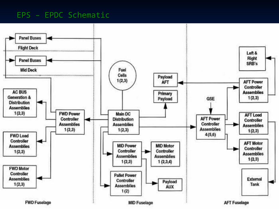
EPS – EPDC SchematicEPS – EPDC Schematic

EPS – Electrical Power Distribution and Control EPS – Electrical Power Distribution and Control
Power controller assemblies' line outputs are Power controller assemblies' line outputs are linked to the load buseslinked to the load buses Essential busesEssential buses Control busesControl buses Payload busesPayload buses AC busesAC buses
These are the primary bus lines that distribute These are the primary bus lines that distribute power to the Orbiter's electrical loadpower to the Orbiter's electrical load

EPS – EPDC SchematicEPS – EPDC Schematic

EPS – Electrical Control AssembliesEPS – Electrical Control Assemblies
Electrical power is distributed to the loads throughout Electrical power is distributed to the loads throughout the STS by a series of power control assemblies the STS by a series of power control assemblies
The EPS power controllers connect the main power The EPS power controllers connect the main power buses to loads located in the three fuselage sectionsbuses to loads located in the three fuselage sections
Distribution and switching assemblies handle Distribution and switching assemblies handle successively lower power as the power distribution successively lower power as the power distribution units further divide the electrical power to the units further divide the electrical power to the individual loadsindividual loads The primary function of these distribution The primary function of these distribution
assemblies is to switch power under remote assemblies is to switch power under remote commandcommand
Often referred to as remote switching devicesOften referred to as remote switching devices

EPS – Electrical Control AssembliesEPS – Electrical Control Assemblies
The largest of these power delivery units are the main The largest of these power delivery units are the main Distribution Assemblies (DAs)Distribution Assemblies (DAs)
DAs connect the fuel cells to their respective main DAs connect the fuel cells to their respective main busesbuses
DAs handle currents as high as 500 ampsDAs handle currents as high as 500 amps
A power contactor (durable contacts opened and A power contactor (durable contacts opened and closed with a motor) is employed in the switching closed with a motor) is employed in the switching circuit to handle the large current loads without circuit to handle the large current loads without arcing or other damagearcing or other damage

EPS – Electrical Control AssembliesEPS – Electrical Control Assemblies
Electrical Assembly Purpose Remote Switching Devices
Current Rating (Amps)
Distribution Assembly (DA)
Connection of fuel cells to main buses
Power contactors
500 A
Power Controller Assemblies (PCA)
Powers larger DC loads
Remote power controllers and relays
20 / 175 A
Load Controller Assemblies (LCA)
Powers smaller DC loads
Hybrid circuit drivers
5 A
Motor Controller Assemblies (MCA)
Powers noncontinuous AC loads
Relays 4 A

EPS – EPDC SchematicEPS – EPDC Schematic

EPS – Electrical Control AssembliesEPS – Electrical Control Assemblies
Distribution AssembliesDistribution Assemblies
The Orbiter's remotely controlled motor-driven DA The Orbiter's remotely controlled motor-driven DA switches are used for loads over 125 ampsswitches are used for loads over 125 amps
DAs control and distribute dc power to DAs control and distribute dc power to corresponding mid power controller assemblies, corresponding mid power controller assemblies, forward power controller assemblies and aft power forward power controller assemblies and aft power controller assembliescontroller assemblies
EPS – Electrical Control AssembliesEPS – Electrical Control Assemblies
Power Controller AssembliesPower Controller Assemblies
The PCAs are used for intermediate load The PCAs are used for intermediate load power distribution for current requirements power distribution for current requirements that range from 3 to 20 ampsthat range from 3 to 20 amps
These devices contains remote power These devices contains remote power controllers and relays for current switchingcontrollers and relays for current switching

EPS – Electrical Control AssembliesEPS – Electrical Control Assemblies
Load Controller AssembliesLoad Controller Assemblies
The LCA is used for the lower power loads that do The LCA is used for the lower power loads that do not exceed 5 ampsnot exceed 5 amps
The LCA units contains solid-state switching The LCA units contains solid-state switching devices called hybrid drivers that have no devices called hybrid drivers that have no mechanical partsmechanical parts

EPS – Electrical Control AssembliesEPS – Electrical Control Assemblies
Motor Controller AssembliesMotor Controller Assemblies
The 10 motor controller assemblies used on the The 10 motor controller assemblies used on the Orbiter furnish ac power for the non-continuous ac Orbiter furnish ac power for the non-continuous ac motor loadsmotor loads Vent doorsVent doors Air data doorsAir data doors Star tracker doorsStar tracker doors Payload bay doors and payload bay latchesPayload bay doors and payload bay latches OMS/RCS motor-actuated valvesOMS/RCS motor-actuated valves

EPS – Main BusesEPS – Main Buses
Main dc busesMain dc buses
Fuel cell 1 MNA busFuel cell 1 MNA bus (500 A) (500 A) Fuel cell 2 MNB busFuel cell 2 MNB bus (500 A) (500 A) Fuel cell 3 MNC bus Fuel cell 3 MNC bus (500 A) (500 A)

EPS – Power Control SchematicEPS – Power Control Schematic

EPS – Main BusesEPS – Main Buses
Each of the main buses feeds the three power Each of the main buses feeds the three power controller assemblies and their loadscontroller assemblies and their loads
Main DC distribution assemblies (DA) Main DC distribution assemblies (DA) Controls the main power distribution on the three Controls the main power distribution on the three
main busesmain buses 500 A max load500 A max load Supplies power to forward, mid and aft power Supplies power to forward, mid and aft power
controller assemblies controller assemblies

EPS – Main BusesEPS – Main Buses
Each DA powers the forward fuselage loads through: Each DA powers the forward fuselage loads through: Three forward fuselage power controller assemblies Three forward fuselage power controller assemblies
(PCAs)(PCAs) Three forward fuselage controller assemblies (LCAs)Three forward fuselage controller assemblies (LCAs) Three forward fuselage motor control assemblies Three forward fuselage motor control assemblies
(MCAs)(MCAs) Nine invertersNine inverters
Each DA powers the mid fuselage loads through:Each DA powers the mid fuselage loads through: Three mid fuselage power controller assemblies (PCAs) Three mid fuselage power controller assemblies (PCAs) Four mid fuselage motor controller assemblies (PCAs)Four mid fuselage motor controller assemblies (PCAs)

EPS – Main Bus Distribution AssemblyEPS – Main Bus Distribution Assembly
DA circuit diagramDA circuit diagram
MNA connected to the two MNA connected to the two other main buses with other main buses with remote power controllers remote power controllers (RPCs)(RPCs)
Each DAs powers the aft Each DAs powers the aft fuselage loads through:fuselage loads through:
Six aft power controller Six aft power controller assemblies (PCA)assemblies (PCA)
Three aft motor controller Three aft motor controller assemblies (MCA)assemblies (MCA)
Three aft load controller Three aft load controller assemblies (LCA)assemblies (LCA)

EPS – AC BusesEPS – AC Buses
The inherent noise in the Orbiter's electric motors and The inherent noise in the Orbiter's electric motors and improved motor efficiency necessitated a separate improved motor efficiency necessitated a separate alternating current power sourcealternating current power source
The Orbiter’s 3-phase AC power is furnished by a The Orbiter’s 3-phase AC power is furnished by a triple-redundant bus system that is fed from the three triple-redundant bus system that is fed from the three DC power busesDC power buses
The AC buses supply 120 Vac 3-phase current at 400 The AC buses supply 120 Vac 3-phase current at 400 Hz with three single-phase inverters for each of the Hz with three single-phase inverters for each of the three AC busesthree AC buses
Total of nine invertersTotal of nine inverters
EPS – AC BusesEPS – AC Buses
Inverters are coupled to the forward power Inverters are coupled to the forward power controller assemblies for use in the controller assemblies for use in the avionics bays and crew cabinavionics bays and crew cabin
Used in the payload bay for the payloads and Used in the payload bay for the payloads and the payload bay door motorsthe payload bay door motors
Used for the SSME controllersUsed for the SSME controllers
AC power is also furnished to the three fuel cell AC power is also furnished to the three fuel cell electrical control units (ECUs)electrical control units (ECUs)

EPS – AC BusesEPS – AC Buses
AC busesAC buses
AC1 bus (750 W)AC1 bus (750 W) AC2 bus (750 W)AC2 bus (750 W) AC3 bus (750 W)AC3 bus (750 W)

EPS – Essential BusesEPS – Essential Buses
Three essential buses supply power to Three essential buses supply power to important flight crew controls and essential important flight crew controls and essential equipment on the Orbiterequipment on the Orbiter
These essential buses are used to restore These essential buses are used to restore power to failed main DC or AC buses, the power to failed main DC or AC buses, the controls, and the switches that are essential controls, and the switches that are essential to spaceflight operationsto spaceflight operations

EPS – Essential BusesEPS – Essential Buses
Each essential bus is tied into the three main buses Each essential bus is tied into the three main buses by one direct connection and two power controller by one direct connection and two power controller assembliesassemblies
The direct link to a main bus becomes the root of The direct link to a main bus becomes the root of the essential bus designationthe essential bus designation
For example, the 1BC essential bus (ESS 1BC) is For example, the 1BC essential bus (ESS 1BC) is connected directly to the main bus Aconnected directly to the main bus A
Fed directly from fuel cell 1Fed directly from fuel cell 1 Two secondary power connections are on the Two secondary power connections are on the
main bus B and C via the power controller main bus B and C via the power controller busesbuses

EPS – Essential BusesEPS – Essential Buses
Essential bus 1BCEssential bus 1BC
ESS 1BC (fuel cell 1 ESS 1BC (fuel cell 1 and MNB + MNC bus and MNB + MNC bus power controllers)power controllers)
ESS 2CA (fuel cell 2 ESS 2CA (fuel cell 2 and MNA + MNC bus and MNA + MNC bus power controllers) power controllers)
ESS 3AB (fuel cell 3 ESS 3AB (fuel cell 3 and MNA + MNB bus and MNA + MNB bus power controllers) power controllers)

EPS – Control BusesEPS – Control Buses
Crew flight deck control and display systems are powered by nine Crew flight deck control and display systems are powered by nine control buses that are each linked to the Orbiter's three separate control buses that are each linked to the Orbiter's three separate power sourcespower sources
Similar scheme to the essential bus configurationSimilar scheme to the essential bus configuration
Each control bus is tied into all three main buses for redundancyEach control bus is tied into all three main buses for redundancy
Only one line is tied directly to a main bus DAOnly one line is tied directly to a main bus DA
No operational loads are powered by the Orbiter's control busesNo operational loads are powered by the Orbiter's control buses
Control BusesControl Buses
CNTL AB1, AB2, AB3 CNTL AB1, AB2, AB3 CNTL BC1, BC2, BC3CNTL BC1, BC2, BC3 CNTL CA1, CA2, CA3CNTL CA1, CA2, CA3

EPS – Payload BusesEPS – Payload Buses
Primary power for the Orbiter payloads comes from Primary power for the Orbiter payloads comes from the main bus MNC which is fed from Fuel Cell 3the main bus MNC which is fed from Fuel Cell 3
Either the MNA and MNB dc buses can also be Either the MNA and MNB dc buses can also be selected for payload power by using cross-tie selected for payload power by using cross-tie switches, or using the AUX PLA or AUX PLB payload switches, or using the AUX PLA or AUX PLB payload bus lines and switchesbus lines and switches
Payload busesPayload buses
Primary Payload Bus PRIPLPrimary Payload Bus PRIPL Aft Payload Bus AFT PLB, AFT PLCAft Payload Bus AFT PLB, AFT PLC Auxiliary Payload Bus AUX PLA, AUX PLBAuxiliary Payload Bus AUX PLA, AUX PLB Cabin Payload Bus CAB PL1, CAB PL2, CAB PL3Cabin Payload Bus CAB PL1, CAB PL2, CAB PL3 AC Payload Bus AC2 PL, AC3 PLAC Payload Bus AC2 PL, AC3 PL

EPS – Ground Service Equipment (GSE) BusEPS – Ground Service Equipment (GSE) Bus
Primary power for the STS and Orbiter is furnished Primary power for the STS and Orbiter is furnished by the three onboard fuel cells from five minutes by the three onboard fuel cells from five minutes before launch to 4-5 hours after landingbefore launch to 4-5 hours after landing
Electrical power during the Orbiter’s processing Electrical power during the Orbiter’s processing cycle is supplied by the GSE on either side of the cycle is supplied by the GSE on either side of the flight missionflight mission From landing to launchFrom landing to launch

EPS – Ground Service Equipment (GSE) BusEPS – Ground Service Equipment (GSE) Bus
GSE powers the Orbiter through its T-0 umbilical GSE powers the Orbiter through its T-0 umbilical panels on the aft sectionpanels on the aft section
External power is also supplied in the Vehicle External power is also supplied in the Vehicle Assembly Building during the one-week assembly Assembly Building during the one-week assembly phase (also GSE through T-0 panel)phase (also GSE through T-0 panel)
Also supplied while on the launch pad for its one-Also supplied while on the launch pad for its one-month preparation (GSE through T-0 panel)month preparation (GSE through T-0 panel)

EPS – GSE BusEPS – GSE Bus
GSE interface on the OrbiterGSE interface on the Orbiter

EPS – Caution and Warning SystemEPS – Caution and Warning System
The Orbiter’s critical systems have 120 sensor The Orbiter’s critical systems have 120 sensor inputs into a monitoring and warning system that inputs into a monitoring and warning system that displays emergency, critical, and important displays emergency, critical, and important conditions or events for the crewconditions or events for the crew
Most of the basic Orbiter systems are represented Most of the basic Orbiter systems are represented on the 40-light Caution and Warning display that on the 40-light Caution and Warning display that augments other display readouts in the crew augments other display readouts in the crew cabincabin
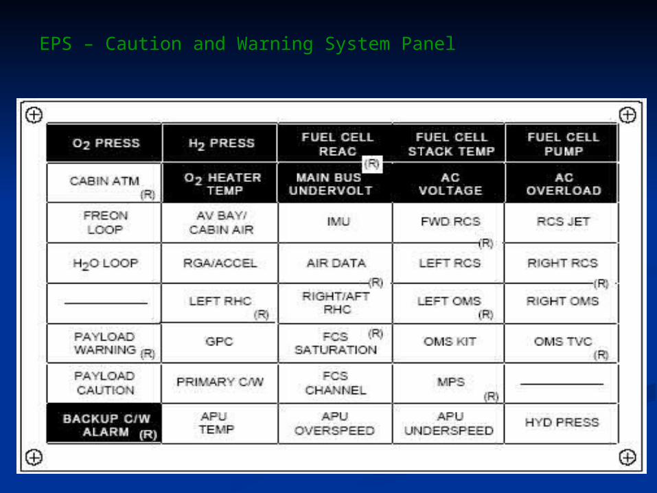
EPS – Caution and Warning System Panel

EPS – Caution and Warning SystemEPS – Caution and Warning System
The Caution and Warning system includes three The Caution and Warning system includes three types of audible alarms to monitor the following:types of audible alarms to monitor the following:
Auxiliary power unitsAuxiliary power units HydraulicsHydraulics Data processing systemData processing system Environmental control and life support systemEnvironmental control and life support system Electrical power systemElectrical power system Flight control systemFlight control system Guidance and navigationGuidance and navigation Main propulsion systemMain propulsion system Reaction control systemReaction control system Orbital maneuvering systemOrbital maneuvering system PayloadsPayloads

EPS Monitor gauges EPS Monitor gauges and Switchesand Switches

Power Reactant Storage and Distribution System (PRSD)
Power Reactant Storage and Distribution System
EPS consumables (LOX & LH2) are scaled to the mission duration, along with breathing oxygen and the OMS/RCS propellants
To minimize the mass of the consumables, the density of the reactants is maximized by storing the reactants as cryogenic liquids in tanks -285oF for the LOX -420oF for the LH2

Power Reactant Storage and Distribution System
Supercritical cryogenic reactants are stored at high pressure Distributed at reduced pressure Heated to gas temperatures needed for electrical
generation within the fuel cells
Five reactant tanks sets are installed for the liquid hydrogen and liquid oxygen in the Orbiter mid fuselage (10 total) for typical mission Fill lines for reactant tanks are connected to the T-
0 aft panels Relief vents and service panels are located in the
mid fuselage

PRSD – Reactant Tanks
EPS cryogenic tanks are grouped in five sets EPS cryogenic tanks are grouped in five sets of two tanksof two tanks One hydrogen One hydrogen One oxygenOne oxygen
Five sets of the tanks are normally installed in Five sets of the tanks are normally installed in the mid fuselage under the payload bay linerthe mid fuselage under the payload bay liner
Number of tank sets installed depends on the Number of tank sets installed depends on the specific mission requirements and the vehiclespecific mission requirements and the vehicle

PRSD – Reactant Tanks
EPS cryogenic EPS cryogenic tanks are grouped in tanks are grouped in five sets of two five sets of two tankstanks One hydrogen One hydrogen One oxygenOne oxygen

PRSD – Reactant Tanks
Up to four additional tank sets can be Up to four additional tank sets can be accommodated on the Extended-accommodated on the Extended-Duration Orbiter (EDO) palletDuration Orbiter (EDO) pallet
For reliability and redundancy, each set For reliability and redundancy, each set of tanks can supply all three fuel cells of tanks can supply all three fuel cells with reactantswith reactants

PRSD TanksPRSD Tanks

PRSD TanksPRSD Tanks

PRSD – Reactant Tank Specs
Oxygen tank
Construction Double-walled, thermally insulated, aluminum alloy and Inconel
spherical unitDimensions 33.3" dia. inner vessel 36.8" dia. outer shellInsulation Vacuum insulation between vessel and shellVolume (internal) 11.2 ft3
Capacity 781 lb LOXWeight 201 lb emptyLOX storage temp -285oFFill time 45 min

PRSD – Reactant Tank Specs
Hydrogen tank
Construction Double-walled, thermally insulated, aluminum alloy and Inconel spherical unit
Dimensions 41.5" dia. inner vessel45.5" dia. outer shell
Insulation Vacuum insulation between vessel and shellVolume (internal) 21.4 ft3 Capacity 92 lb LH2Weight 216 lb emptyLH2 storage temp-420oFFill time 45 min

PRSD – Reactant Tanks
Tank heaters
Each hydrogen tank has one heater probe with two heater elements to vaporize the reactants to maintain constant pressure within the tanks
Each oxygen tank has two heater probes with two heater elements on each probe
Temperature and pressure sensors monitor the tanks, as well as the reactants throughout the distribution system, including the inlet to the fuel cells

PRSD – Reactant Distribution
Reactants are supplied to the fuel cells through common LOX and LH2 distribution manifolds
Check valves for each tank prevent flow from one tank to another
LOX distribution system also supplies the ECLSS O2 for the cabin atmosphere

PRSD – Reactant Distribution
GSE connection supplies the reactant manifolds and the ECLSS LOX until 2 min 35 sec before launch
Oxygen distribution pressure 803-883 psi (manifold and fuel cell
interface)Hydrogen distribution pressure 200-243 psi (manifold
and fuel cell interface)
Oxygen tank relief pressure 1,005 psiaOxygen manifold relief pressure 975 psiaHydrogen tank relief pressure 302 psiaHydrogen manifold relief pressure 290 psia

PRSD TankReadouts

TheThe E ENNDD