Embed Size (px)
Citation preview

Asa Sproul
MSEE Defense
April 3rd, 2015
Advisory Committee:
Duane C. Hanselman, Associate Professor of Electrical and Computer Engineering, Advisor
Bruce E. Segee, Professor of Electrical and Computer Engineering
Nathan D. Weise , Assistant Professor of Electrical and Computer Engineering at Marquette University

• Introduction
• Theory
• Testing
• Discussion
• Conclusion
Content
April 3rd, 2015 Asa Sproul 2

April 3rd, 2015 Asa Sproul 3

• Ocean wave energy is highly underutilized
• 15-20x more available energy/m2 than wind or solar
• Estimated 8000-80,000 TWh/yr available throughout ocean
• Economical viability for capture not yet achieved
April 3rd, 2015 Asa Sproul 4
Background
• WEC: Wave Energy Converter
• Mechanical structures absorb wave power
• Power capturing structure coupled with generator
• Maximum capture through mechanical resonance
• Can operate in various water depths
April 3rd, 2015 Asa Sproul 5
What is a WEC?

• LIMPET:
• Pelamis:
April 3rd, 2015 Asa Sproul 6
Technology Under Development

• Wave Dragon:
• PowerBuoy:
April 3rd, 2015 Asa Sproul 7
Technology Under Development con’t
• No universal design converged upon
• Find viable control method of novel prototype
• Maximize mechanical efficiency
• Provide groundwork for large-scale device
April 3rd, 2015 Asa Sproul 8
Research Purpose

April 3rd, 2015 Asa Sproul 9

• 𝐹 = 𝑚𝑥 + 𝑅𝑥 + 𝑆𝑥
• Can be compared with power
absorbing structure of WEC
• Provides basis for control
• 𝐹 = 𝐹𝑤𝑎𝑣𝑒
April 3rd, 2015 Asa Sproul 10
Linearized Wave Equation

• 𝐹𝑔𝑒𝑛 = 𝑚𝑔𝑒𝑛𝑥 + 𝑅𝑔𝑒𝑛𝑥 + 𝑆𝑔𝑒𝑛𝑥
• 𝐹𝑔𝑒𝑛 ∝ 𝑇𝑔𝑒𝑛 ∝ 𝐼𝑔𝑒𝑛
• Current controller may be used
• Controller input based on acceleration, speed, and position
April 3rd, 2015 Asa Sproul 11
Assisted Movement

April 3rd, 2015 Asa Sproul 12
Simplified Control Diagram

April 3rd, 2015 Asa Sproul 13
RTI F2

• Typically expressed as available power per meter crest length
• 𝑃𝑤𝑎𝑣𝑒,𝑚𝑐𝑙 =1
8𝜌𝑔𝐻2𝑐𝑔
• Equation takes 3 forms
1. Shallow
2. Intermediate
3. Deep
• Equation form depends on water depth and wavelength
April 3rd, 2015 Asa Sproul 14
Wave Power
𝜌 = mass density of liquid
𝑔 = acceleration due to gravity
𝐻 = peak-to-trough wave height
𝑐𝑔 = wave’s group velocity

• Means of measuring efficiency and economic viability
• Defined as “The width of the wavefront (assuming uni-
directional waves) that contain the same amount of power as
that absorbed by the WEC.” Price et al., 2009
• 𝐶𝑊 = 𝑃𝑎𝑏𝑠𝑜𝑟𝑏𝑒𝑑
𝑃𝑤𝑎𝑣𝑒,𝑚𝑐𝑙
April 3rd, 2015 Asa Sproul 15
Capture Width

April 3rd, 2015 Asa Sproul 16
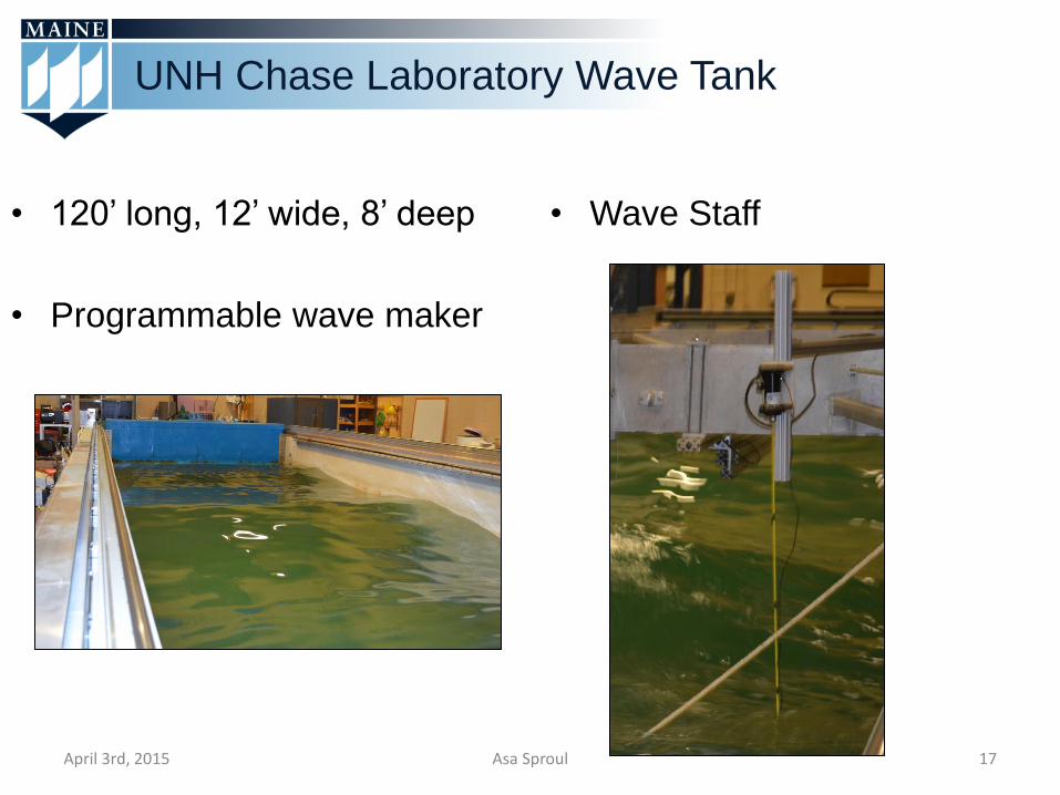
• 120’ long, 12’ wide, 8’ deep
• Programmable wave maker
• Wave Staff
April 3rd, 2015 Asa Sproul 17
UNH Chase Laboratory Wave Tank

• Mounted frame
• Vessel facing
wave maker
• Wave attenuator
at far end
April 3rd, 2015 Asa Sproul 18
Device Setup

• Motor/generator
• Brushed DC
• Coupled with gearbox
• Controlled from control
platform
April 3rd, 2015 Asa Sproul 19
Power Take Off

• CUSP Educational Lab Inverter
• MATLAB, Simulink, dSPACE
April 3rd, 2015 Asa Sproul 20
Hardware and Software

• Determine optimal control technique
• Validate wave front parallel configuration
• Operate device as intended for structural considerations
• Analyze system losses
• Provide groundwork for ongoing development
April 3rd, 2015 Asa Sproul 21
Objectives

• Wave height and wave period
• Control methods
– Damping control
– Damping + inertial control
• Added mass
• Plate angle
• Frictional correction
April 3rd, 2015 Asa Sproul 22
Test Variables

• 𝑃1 = 𝐼𝑉
• 𝑃2 = 𝑃1 + 𝐼2𝑅
• 𝑃3 = 𝑃2 + 𝐵𝜔2
• 𝑃4 = 𝑃3 + 𝑇𝑠𝑡𝑖𝑐
• 𝑃5 =𝑃4
0.93
April 3rd, 2015 Asa Sproul 23
Capture Widths and System Losses
𝐶𝑊1−5 =𝑃1−5
𝑃𝑤𝑎𝑣𝑒,𝑚𝑐𝑙
April 3rd, 2015 Asa Sproul 24
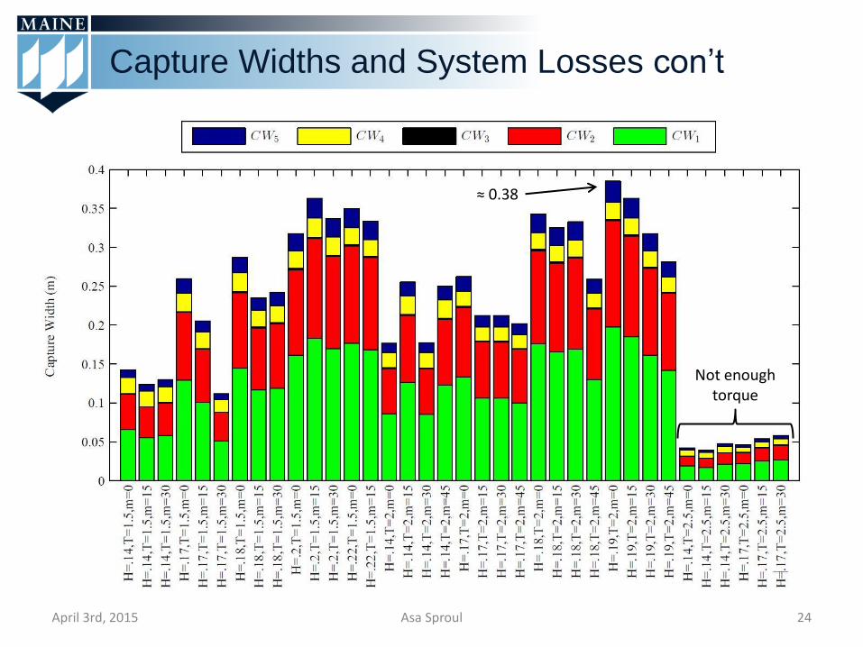
Capture Widths and System Losses con’t
≈ 0.38
Not enough torque
April 3rd, 2015 Asa Sproul 25

• Stationary frame will be floating at full scale
• Capture width needs further improvement
• Prototype should be optimized to panchromatic conditions
• Other control strategies should be tested
April 3rd, 2015 Asa Sproul 26
Things to Consider

• Direct drive would eliminate frictional losses due to gearbox
• Generator optimized for low speed
• Generator optimized for high torque
• Brushless DC would provide better efficiency than brushed
April 3rd, 2015 Asa Sproul 27
Power Take Off Improvements
April 3rd, 2015 Asa Sproul 28
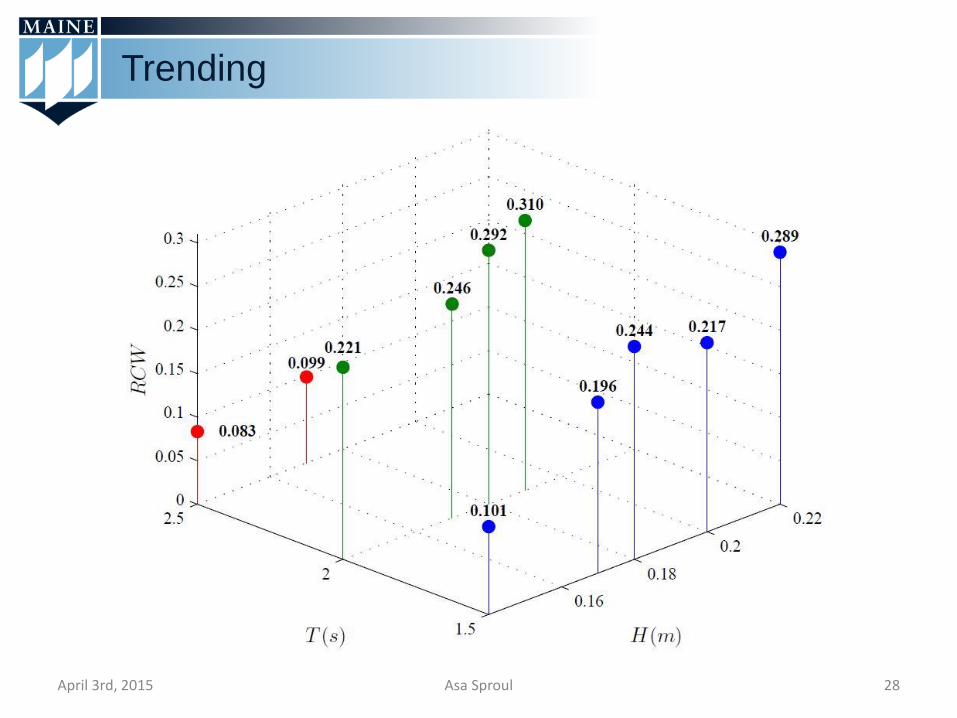
Trending

• Prototype to full scale parameter estimates
• Froude scale factor = 11
April 3rd, 2015 Asa Sproul 29
Froude Scaling
Parameter Prototype Full Scale
Generator 250W 1MW
Structure Width 1m 11m
PTO Peak Torque 1.35Nm 19.7kNm
PTO Peak Speed 42.3rad/s 12.8rad/s
Optimal Wave Period 2s 6.6s

April 3rd, 2015 Asa Sproul 30

• RTI F2 tested
• Efficiency maximized through control
• Linear wave theory basis of control theory
• Sufficient test data captured for analysis and
improvements
April 3rd, 2015 Asa Sproul 31
Overview

• RTI working on next set of prototypes
• RTI F2S and RTI F2DS
• Utilize swingarm and dual swingarm configurations
• Better economic feasibility
• Stronger structures
April 3rd, 2015 Asa Sproul 32
Future Models

• Nathan Weise
• Duane Hanselman
• Bruce Segee
• John Rohrer
• Sean Lewis
• Matt Rowell
• Matt Hall
• Lance Doiron
• Arjun Prabu
• Adam Nickerson
• Lonnie Labonte
• Sara Lemik
April 3rd, 2015 Asa Sproul 33
Special Thanks

April 3rd, 2015 Asa Sproul 34

• J. Vining and A. Muetze, “Economic factors and incentives for ocean wave energy conversion,” IEEE Trans. Ind. Appl., vol. 45, pp. 547–
554, March 2009. Slide 4
• http://upload.wikimedia.org/wikipedia/en/thumb/2/26/Maine_Black_Bears_Logo.svg/1280px-Maine_Black_Bears_Logo.svg.png Black
Bear image on section headers
• N. Ahmed and M. Mueller, “Impact of airflow impingment on heat transfer from induction generators in oscillating water columns,” in Proc.
International Conference on Power Electronics, Machines and Drives (PEMD), pp. 1–6, March 2012. LIMPET picture
• N. Muller, S. Kouro, J. Glaria, and M. Malinowski, “Medium-voltage power converter interface for wave dragon wave energy conversion
system,” in Proc. IEEE Energy Conversion Congress and Exposition (ECCE), pp. 352–358, Sept 2013. Wave Dragon picture
• R. Yemm, D. Pizer, C. Retzler, and R. Henderson, “Pelamis: experience from concept to connection,” Philosophical Transactions of the
Royal Society A: Mathematical, Physical and Engineering Sciences, vol. 370, no. 1959, pp. 365–380, 2012. Pelamis picture
• A. F. de O. Falco, “Wave energy utilization: A review of the technologies,” Renewable and Sustainable Energy Reviews, vol. 14, no. 3, pp.
899 – 918, 2010. Power Buoy picture
• J. Falnes, Ocean Waves and Oscillating Systems. Cambridge University Press, 2002. Mass Spring Damper picture
April 3rd, 2015 Asa Sproul 35
References


